EP3827353B1 - Datenübertragungssystem mit drahtloser beleuchtung - Google Patents
Datenübertragungssystem mit drahtloser beleuchtung Download PDFInfo
- Publication number
- EP3827353B1 EP3827353B1 EP18928114.0A EP18928114A EP3827353B1 EP 3827353 B1 EP3827353 B1 EP 3827353B1 EP 18928114 A EP18928114 A EP 18928114A EP 3827353 B1 EP3827353 B1 EP 3827353B1
- Authority
- EP
- European Patent Office
- Prior art keywords
- data
- human interface
- interface device
- keyboard
- mouse
- Prior art date
- Legal status (The legal status is an assumption and is not a legal conclusion. Google has not performed a legal analysis and makes no representation as to the accuracy of the status listed.)
- Active
Links
Images






Classifications
-
- G—PHYSICS
- G06—COMPUTING OR CALCULATING; COUNTING
- G06F—ELECTRIC DIGITAL DATA PROCESSING
- G06F3/00—Input arrangements for transferring data to be processed into a form capable of being handled by the computer; Output arrangements for transferring data from processing unit to output unit, e.g. interface arrangements
- G06F3/01—Input arrangements or combined input and output arrangements for interaction between user and computer
- G06F3/03—Arrangements for converting the position or the displacement of a member into a coded form
- G06F3/033—Pointing devices displaced or positioned by the user, e.g. mice, trackballs, pens or joysticks; Accessories therefor
- G06F3/038—Control and interface arrangements therefor, e.g. drivers or device-embedded control circuitry
-
- G—PHYSICS
- G06—COMPUTING OR CALCULATING; COUNTING
- G06F—ELECTRIC DIGITAL DATA PROCESSING
- G06F13/00—Interconnection of, or transfer of information or other signals between, memories, input/output devices or central processing units
- G06F13/38—Information transfer, e.g. on bus
- G06F13/382—Information transfer, e.g. on bus using universal interface adapter
- G06F13/385—Information transfer, e.g. on bus using universal interface adapter for adaptation of a particular data processing system to different peripheral devices
-
- G—PHYSICS
- G06—COMPUTING OR CALCULATING; COUNTING
- G06F—ELECTRIC DIGITAL DATA PROCESSING
- G06F3/00—Input arrangements for transferring data to be processed into a form capable of being handled by the computer; Output arrangements for transferring data from processing unit to output unit, e.g. interface arrangements
- G06F3/01—Input arrangements or combined input and output arrangements for interaction between user and computer
- G06F3/02—Input arrangements using manually operated switches, e.g. using keyboards or dials
- G06F3/023—Arrangements for converting discrete items of information into a coded form, e.g. arrangements for interpreting keyboard generated codes as alphanumeric codes, operand codes or instruction codes
-
- G—PHYSICS
- G06—COMPUTING OR CALCULATING; COUNTING
- G06F—ELECTRIC DIGITAL DATA PROCESSING
- G06F3/00—Input arrangements for transferring data to be processed into a form capable of being handled by the computer; Output arrangements for transferring data from processing unit to output unit, e.g. interface arrangements
- G06F3/01—Input arrangements or combined input and output arrangements for interaction between user and computer
- G06F3/02—Input arrangements using manually operated switches, e.g. using keyboards or dials
- G06F3/023—Arrangements for converting discrete items of information into a coded form, e.g. arrangements for interpreting keyboard generated codes as alphanumeric codes, operand codes or instruction codes
- G06F3/0231—Cordless keyboards
-
- G—PHYSICS
- G06—COMPUTING OR CALCULATING; COUNTING
- G06F—ELECTRIC DIGITAL DATA PROCESSING
- G06F3/00—Input arrangements for transferring data to be processed into a form capable of being handled by the computer; Output arrangements for transferring data from processing unit to output unit, e.g. interface arrangements
- G06F3/01—Input arrangements or combined input and output arrangements for interaction between user and computer
- G06F3/03—Arrangements for converting the position or the displacement of a member into a coded form
- G06F3/033—Pointing devices displaced or positioned by the user, e.g. mice, trackballs, pens or joysticks; Accessories therefor
-
- G—PHYSICS
- G06—COMPUTING OR CALCULATING; COUNTING
- G06F—ELECTRIC DIGITAL DATA PROCESSING
- G06F3/00—Input arrangements for transferring data to be processed into a form capable of being handled by the computer; Output arrangements for transferring data from processing unit to output unit, e.g. interface arrangements
- G06F3/01—Input arrangements or combined input and output arrangements for interaction between user and computer
- G06F3/03—Arrangements for converting the position or the displacement of a member into a coded form
- G06F3/033—Pointing devices displaced or positioned by the user, e.g. mice, trackballs, pens or joysticks; Accessories therefor
- G06F3/0354—Pointing devices displaced or positioned by the user, e.g. mice, trackballs, pens or joysticks; Accessories therefor with detection of two-dimensional [2D] relative movements between the device, or an operating part thereof, and a plane or surface, e.g. 2D mice, trackballs, pens or pucks
- G06F3/03543—Mice or pucks
-
- G—PHYSICS
- G06—COMPUTING OR CALCULATING; COUNTING
- G06F—ELECTRIC DIGITAL DATA PROCESSING
- G06F3/00—Input arrangements for transferring data to be processed into a form capable of being handled by the computer; Output arrangements for transferring data from processing unit to output unit, e.g. interface arrangements
- G06F3/01—Input arrangements or combined input and output arrangements for interaction between user and computer
- G06F3/03—Arrangements for converting the position or the displacement of a member into a coded form
- G06F3/033—Pointing devices displaced or positioned by the user, e.g. mice, trackballs, pens or joysticks; Accessories therefor
- G06F3/038—Control and interface arrangements therefor, e.g. drivers or device-embedded control circuitry
- G06F3/0383—Signal control means within the pointing device
-
- H—ELECTRICITY
- H05—ELECTRIC TECHNIQUES NOT OTHERWISE PROVIDED FOR
- H05B—ELECTRIC HEATING; ELECTRIC LIGHT SOURCES NOT OTHERWISE PROVIDED FOR; CIRCUIT ARRANGEMENTS FOR ELECTRIC LIGHT SOURCES, IN GENERAL
- H05B45/00—Circuit arrangements for operating light-emitting diodes [LED]
- H05B45/20—Controlling the colour of the light
-
- H—ELECTRICITY
- H05—ELECTRIC TECHNIQUES NOT OTHERWISE PROVIDED FOR
- H05B—ELECTRIC HEATING; ELECTRIC LIGHT SOURCES NOT OTHERWISE PROVIDED FOR; CIRCUIT ARRANGEMENTS FOR ELECTRIC LIGHT SOURCES, IN GENERAL
- H05B47/00—Circuit arrangements for operating light sources in general, i.e. where the type of light source is not relevant
- H05B47/10—Controlling the light source
- H05B47/175—Controlling the light source by remote control
- H05B47/19—Controlling the light source by remote control via wireless transmission
-
- G—PHYSICS
- G06—COMPUTING OR CALCULATING; COUNTING
- G06F—ELECTRIC DIGITAL DATA PROCESSING
- G06F2203/00—Indexing scheme relating to G06F3/00 - G06F3/048
- G06F2203/033—Indexing scheme relating to G06F3/033
- G06F2203/0337—Status LEDs integrated in the mouse to provide visual feedback to the user about the status of the input device, the PC, or the user
-
- G—PHYSICS
- G06—COMPUTING OR CALCULATING; COUNTING
- G06F—ELECTRIC DIGITAL DATA PROCESSING
- G06F2203/00—Indexing scheme relating to G06F3/00 - G06F3/048
- G06F2203/038—Indexing scheme relating to G06F3/038
- G06F2203/0384—Wireless input, i.e. hardware and software details of wireless interface arrangements for pointing devices
Definitions
- Various aspects of this disclosure generally relate to wireless communication systems, and more particularly, to a wireless lighting effect configuration data transmission system.
- a human interface device is a type of computer device usually used by humans that takes input from humans and gives output to humans.
- Common human interface devices may include keyboard, pointing devices (e.g., mouse, trackball, touchpad, pointing stick, light pen), touchscreen, magnetic stripe reader, graphics tablet, joystick, gamepad, analog stick, webcam, fingerprint scanner, etc.
- a dongle is a small piece of hardware that connects to a computing device to provide the computing device with additional functionality (e.g., wireless connectivity to human interface devices).
- a wireless mouse may transmit data via infrared radiation (IR) or radio (e.g., Bluetooth and Wi-Fi).
- the receiver of a wireless mouse may be a dongle that is connected to the computer through a serial or USB port, or can be built in.
- a wireless keyboard is a computer keyboard that allows the user to communicate with computers, tablets, or laptops with the help of radio frequency (RF) or infrared radiation technology.
- RF radio frequency
- a wireless keyboard may be connected using RF technology using a transmitter and a receiver.
- the radio transmitter may be inside the wireless keyboard.
- the radio receiver may be a dongle that is plugged into a keyboard port or USB port. Once the receiver and transmitter are plugged in, the computer recognizes the wireless keyboard as if it were connected via a cable.
- the wireless mouse and the wireless keyboard may use light-emitting diode (LED) components to present lighting effect.
- LED light-emitting diode
- traditional wireless mouse and wireless keyboard architecture there may be a dedicated USB dongle associated to each HID device.
- the wireless mouse and the wireless keyboard may support wireless Chroma function. That is, the wireless mouse and the wireless keyboard may adjust their lighting effect based on configuration data received from their respective USB dongle.
- the wireless mouse and the wireless keyboard operate independently from each other.
- FIG. 1A is a diagram illustrating an example of a traditional system 100 that includes a wireless mouse 106 and a wireless keyboard 104.
- the wireless mouse 106 is connected to a computing device 102 through a USB dongle 110
- the wireless keyboard 104 is connected to the computing device 102 through a USB dongle 108.
- the USB dongle 110 is the receiver of the wireless mouse 106
- the USB dongle 108 is the receiver of the wireless keyboard 104.
- the wireless mouse 106 and the wireless keyboard 104 may interfere with each other as the RF transmission is not coordinated.
- the close proximity of the dongles 108 and 110 may create unwanted RF degradation to the systems, which is known as power blocking.
- two USB ports of the computing device 102 are occupied as each HID device needs one USB dongle.
- Prior art US 2007/019771 discloses a communication protocol for use in a wireless network, the wireless network having a transceiver and a plurality of wireless devices, at least one wireless device configured as an unidirectional device and at least one other wireless device configured as a bidirectional device.
- Prior art WO 02/19630 relates to wireless communications, and more particularly, to a multilink receiver for multiple cordless applications.
- Prior art US 5881366 discloses a method and apparatus for establishing a standardized communications protocol for wireless communications between a host and one or more peripheral devices such as joysticks, mice, gamepads, remote controllers or other devices.
- Prior art US 2005/090200 relates generally to communication systems; and, more particularly, it relates to synchronization of communication between various devices within such communication systems.
- a system and a method to transmit lighting effect configuration data to multiple human interface devices (HID) using a single dongle e.g., a USB dongle
- the system and the method allow two input devices (e.g., a wireless mouse and a wireless keyboard) to communicate with a single dongle on one communication channel.
- the performance of the two input devices is on-par with wired devices.
- the wireless system may divide the channel bandwidth into transmission timeslots, and dedicated timeslots may be allocated to input devices for data transmission, and the acknowledgement and lighting effect configuration data may be returned to the input devices in a common slot.
- a method, a computer readable medium, and an apparatus for wireless communication are provided.
- the apparatus may be a dongle.
- the apparatus may receive, via a radio frequency channel, a first data from a first human interface device at a first time slot of a frame.
- the apparatus may transmit the first data to a computing device coupled to the apparatus.
- the apparatus may receive, via the radio frequency channel, a second data from a second human interface device at a second time slot of the frame.
- the apparatus may transmit the second data to the computing device.
- the apparatus may transmit, via the radio frequency channel at a third time slot of the frame, a first acknowledgment to the first data and a first lighting effect configuration data for the first human interface device, a second acknowledgment to the second data and a second lighting effect configuration data for the second human interface device.
- the one or more aspects include the features hereinafter fully described and particularly pointed out in the claims.
- the following description and the annexed drawings set forth in detail certain illustrative features of the one or more aspects. These features are indicative, however, of but a few of the various ways in which the principles of various aspects may be employed, and this description is intended to include all such aspects.
- processors include microprocessors, microcontrollers, graphics processing units (GPUs), central processing units (CPUs), application processors, digital signal processors (DSPs), reduced instruction set computing (RISC) processors, systems on a chip (SoC), baseband processors, field programmable gate arrays (FPGAs), programmable logic devices (PLDs), state machines, gated logic, discrete hardware circuits, and other suitable hardware configured to perform the various functionality described throughout this disclosure.
- processors in the processing system may execute software.
- Software shall be construed broadly to mean instructions, instruction sets, code, code segments, program code, programs, subprograms, software components, applications, software applications, software packages, routines, subroutines, objects, executables, threads of execution, procedures, functions, etc., whether referred to as software, firmware, middleware, microcode, hardware description language, or otherwise.
- the functions described may be implemented in hardware, software, or any combination thereof. If implemented in software, the functions may be stored on or encoded as one or more instructions or code on a computer-readable medium.
- Computer-readable media includes computer storage media. Storage media may be any available media that can be accessed by a computer.
- such computer-readable media may include a random-access memory (RAM), a read-only memory (ROM), an electrically erasable programmable ROM (EEPROM), optical disk storage, magnetic disk storage, other magnetic storage devices, combinations of the aforementioned types of computer-readable media, or any other medium that can be used to store computer executable code in the form of instructions or data structures that can be accessed by a computer.
- FIG. 1B is a diagram illustrating an example of a data transmission system 150 that includes a wireless mouse 156 and a wireless keyboard 154.
- both the wireless mouse 156 and the wireless keyboard 154 are connected to a computing device 152 through a shared USB dongle 158.
- the USB dongle 158 is the receiver of both the wireless mouse 156 and the wireless keyboard 154.
- the data transmission system 150 makes use of a single USB dongle 158 to communicate with the wireless mouse 156 and the wireless keyboard 154 concurrently.
- the wireless mouse 156 may upload mouse data that includes movement and button status to the USB dongle 158 at the radio frequency of 1000 Hz.
- the wireless keyboard 154 may upload keys pressed status to the USB dongle 158 at the radio frequency of 1000 Hz.
- the USB dongle 158 may download lighting effect configuration data to the wireless mouse 156 and the wireless keyboard 154 concurrently at the frequency of 30 frames per second. Each transmission may be completed in a given time slot.
- a data transmission system may include a USB dongle, which may be able to support two or more human interface devices (e.g., one wireless mouse and one wireless keyboard) concurrently.
- the human interface devices may transmit HID data to the USB dongle at the radio frequency of 1000 Hz.
- the USB dongle may stream HID lighting effect configuration data (may be referred to as Chroma data) to the human interface devices at the frequency of 30 frames per second.
- the human interface devices may use the HID lighting effect configuration data to adjust their respective lighting effect.
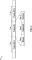
- FIG. 2 is a diagram 200 illustrating an example of an architecture for data transmission between a dongle and two human interface devices (e.g., a wireless mouse and a wireless keyboard).
- data transmission is divided into frames of T ⁇ s (microsecond).
- Each frame may be sub-divided into three time slots for mouse, keyboard, and Chroma data.
- the duration of each time slot may be allocated according to the data bandwidth required by the function associated with the time slot.
- the dongle may enter receive mode (RX) in order to receive data from mouse and keyboard respectively.
- the dongle may stay at the receive mode for two time slots (slot 1 and slot 2).
- the dongle changes to transmit mode (TX) at slot 3 in order to transmit acknowledgment (ACK) and Chroma data to the mouse and/or keyboard.
- RX receive mode
- TX transmit mode
- each frame may be sub-divided into N time slots, N being greater than or equal to three.
- N-1 time slots may be used to receive data from N -1 human interface devices, which may work concurrently with a computing device via a dongle coupled to the computing device.
- One time slot may be used to transmit ACK and Chroma data from the dongle to the N -1 human interface devices.
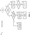
- FIG. 3 is a flowchart 300 of a method of operating a dongle at the first time slot in the data transmission system described above in FIG. 2 .
- the method may be performed by an apparatus (e.g., apparatus 1202/1202' described below with reference to FIG. 12 or 13 ).
- the apparatus may be the dongle.
- the apparatus may determine whether it is connected to a wireless mouse. If it is determined that the apparatus is connected to a wireless mouse, the apparatus may proceed to 306. If it is determined that the apparatus is not connected to a wireless mouse, the apparatus may proceed to 304.
- the apparatus may wait for mouse data (e.g., data regarding the movement and button status of the wireless mouse) to arrive.
- mouse data e.g., data regarding the movement and button status of the wireless mouse
- the apparatus may determine whether the mouse data is received. If the mouse data is received, the apparatus may proceed to 316. At 316, the apparatus may set an acknowledgment flag for the mouse data.
- the apparatus may determine whether a wireless mouse is trying to connect to the apparatus. If it is determined that a wireless mouse is trying to connect, the apparatus may proceed to 310. If it is determined that a wireless mouse is not trying to connect, the apparatus may proceed to 308.
- the apparatus may perform a connection sequence to get connected with the wireless mouse.
- the apparatus is connected to the wireless mouse.
- the apparatus may transmit beacon for connection and synchronization with a wireless mouse.
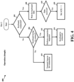
- FIG. 4 is a flowchart 400 of a method of operating a dongle at the second time slot in the data transmission system described above in FIG. 2 .
- the method may be performed by an apparatus (e.g., apparatus 1202/1202' described below with reference to FIG. 12 or 13 ).
- the apparatus may be the dongle.
- the apparatus may determine whether it is connected to a wireless keyboard. If it is determined that the apparatus is connected to a wireless keyboard, the apparatus may proceed to 408. If it is determined that the apparatus is not connected to a wireless keyboard, the apparatus may proceed to 406.
- the apparatus may wait for keyboard data (e.g., data regarding keys pressed status of the wireless keyboard) to arrive.
- keyboard data e.g., data regarding keys pressed status of the wireless keyboard
- the apparatus may determine whether the keyboard data is received. If the keyboard data is received, the apparatus may proceed to 420. At 420, the apparatus may set an acknowledgment flag for the keyboard data.
- the apparatus may determine whether a wireless keyboard is trying to connect to the apparatus. If it is determined that a wireless keyboard is trying to connect, the apparatus may proceed to 412. If it is determined that a wireless keyboard is not trying to connect, the apparatus may proceed to 410.
- the apparatus may perform a connection sequence to get connected with the wireless keyboard.
- the apparatus is connected to the wireless keyboard.
- the apparatus may transmit beacon for connection and synchronization with a wireless keyboard.
- FIG. 5 is a flowchart 500 of a method of operating a dongle at the third time slot in the data transmission system described above in FIG. 2 .
- the method may be performed by an apparatus (e.g., apparatus 1202/1202' described below with reference to FIG. 12 or 13 ).
- the apparatus may be the dongle.
- the apparatus may determine whether an acknowledgment flag for mouse data or keyboard data is set. If it is determined that an acknowledgment flag for mouse data or keyboard data is set, the apparatus may proceed to 504. If it is determined that no acknowledgment flag for mouse data or keyboard data is set, the apparatus may proceed to 506.
- the apparatus may set RF to idle at the third time slot.
- the apparatus may determine whether Chroma data for the wireless mouse or wireless keyboard is ready. If the Chroma data for the wireless mouse or wireless keyboard is ready, the apparatus may proceed to 508. If no Chroma data for the wireless mouse or wireless keyboard is ready, the apparatus may proceed to 510.
- the apparatus may send acknowledgement to the mouse data and/or the keyboard data, as well as Chroma data.
- the apparatus may send only acknowledgement to the mouse data and/or the keyboard data.
- FIG. 6 is a flowchart 600 of a method of operating a wireless mouse at the first time slot in the data transmission system described above in FIG. 2 .
- the method may be performed by the wireless mouse.
- the mouse may determine whether it is connected to a dongle wirelessly. If it is determined that the mouse is connected to a dongle, the mouse may proceed to 608. If it is determined that the mouse is not connected to a dongle, the mouse may proceed to 604.
- the mouse may determine whether mouse data (e.g., data regarding the movement and button status of the wireless mouse) is ready to send. If mouse data is ready to send, the mouse may proceed to 618. If mouse data is not ready to send, the mouse may proceed to 620.
- mouse data e.g., data regarding the movement and button status of the wireless mouse
- the mouse may send mouse data to the dongle.
- the mouse may set a flag for waiting acknowledgment to the mouse data.
- the mouse may set RF to idle at the first time slot.
- the mouse may determine whether a beacon is received. If a beacon is received, the mouse may proceed to 612. If a beacon is not received, the mouse may proceed to 610.
- the mouse may perform a connection sequence to connect to the dongle.
- the mouse is connected to the dongle.
- the mouse may listen for beacon data.
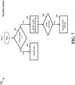
- FIG. 7 is a flowchart 700 of a method of operating a wireless mouse at the third time slot in the data transmission system described above in FIG. 2 .
- the method may be performed by the wireless mouse.
- the mouse may determine whether the flag for waiting acknowledgment is set. If the flag for waiting acknowledgment is set, the mouse may proceed to 706. If the flag for waiting acknowledgment is not set, the mouse may proceed to 704.
- the mouse may set RF to receive mode and wait for the acknowledgment data.
- the mouse may determine whether acknowledgment is received. If acknowledgment is received, the mouse may proceed to 710.
- the mouse may process the received acknowledgment and Chroma data for the mouse.
- the mouse may set RF to idle at the third time slot.
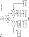
- FIG. 8 is a flowchart 800 of a method of operating a wireless keyboard at the second time slot in the data transmission system described above in FIG. 2 .
- the method may be performed by the wireless keyboard.
- the keyboard may determine whether it is connected to a dongle wirelessly. If it is determined that the keyboard is connected to a dongle, the keyboard may proceed to 806. If it is determined that the keyboard is not connected to a dongle, the keyboard may proceed to 804.
- the keyboard may determine whether keyboard data (e.g., data regarding keys pressed status of the wireless keyboard) is ready to send. If keyboard data is ready to send, the keyboard may proceed to 816. If keyboard data is not ready to send, the keyboard may proceed to 820.
- keyboard data e.g., data regarding keys pressed status of the wireless keyboard
- the keyboard may send keyboard data to the dongle.
- the keyboard may set a flag for waiting acknowledgment to the keyboard data.
- the keyboard may set RF to idle at the second time slot.
- the keyboard may determine whether a beacon is received. If a beacon is received, the keyboard may proceed to 812. If a beacon is not received, the keyboard may proceed to 810.
- the keyboard may perform a connection sequence to connect to the dongle.
- the keyboard is connected to the dongle.
- the keyboard may listen for beacon data.
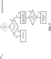
- FIG. 9 is a flowchart 900 of a method of operating a wireless keyboard at the third time slot in the data transmission system described above in FIG. 2 .
- the method may be performed by the wireless keyboard.
- the keyboard may determine whether the flag for waiting acknowledgment is set. If the flag for waiting acknowledgment is set, the keyboard may proceed to 906. If the flag for waiting acknowledgment is not set, the keyboard may proceed to 904.
- the keyboard may set RF to receive mode and wait for the acknowledgment data.
- the keyboard may determine whether acknowledgment is received. If acknowledgment is received, the keyboard may proceed to 910.
- the keyboard may process the received acknowledgment and Chroma data for the keyboard.
- the keyboard may set RF to idle at the third time slot.
- FIG. 10 is a diagram 1000 illustrating an example of data transmissions between a dongle 1002, a mouse 1004, and a keyboard 1006.
- the mouse 1004 may be a wireless mouse and the keyboard 1006 may be a wireless keyboard.
- the data transmissions in the example may occur in the data transmission system described above with reference to FIG. 2 .
- both the mouse 1004 and the keyboard 1006 have HID data to transmit to the dongle 1002.
- slot 1 the mouse 1004 transmits HID data to the dongle 1002.
- slot 2 the keyboard 1006 transmits HID data to the dongle 1002.
- the mouse 1004 and the keyboard 1006 change to RX mode.
- the dongle 1002 transmits ACK to the mouse 1004 and the keyboard 1006, as well as Chroma data to the mouse 1004.
- the mouse 1004 receives ACK, which indicates the success of previous HID transmission.
- the mouse 1004 also receives the Chroma data to configure the lighting effect of the mouse 1004.
- the keyboard 1006 receives ACK, which indicate the success of previous HID transmission.
- the mouse 1004 has HID data to transmit.
- slot 1 the mouse 1004 transmits HID data to the dongle 1002.
- slot 2 no transmission from the keyboard 1006.
- the keyboard 1006 is placed in idle mode.
- slot 3 the mouse 1004 changes to RX mode.
- the dongle 1002 transmits ACK to the mouse 1004, as well as Chroma data to the mouse 1004.
- the mouse 1004 receives ACK, which indicate the success of previous HID transmission.
- the mouse 1004 also receives Chroma data to configure the lighting effect of the mouse 1004.
- the keyboard 1006 has HID data to transmit.
- slot 1 no transmission from the mouse 1004.
- the mouse 1004 is placed in idle mode.
- slot 2 the keyboard 1006 transmits HID data to the dongle 1002.
- slot 3 the keyboard 1006 changes to RX mode.
- the dongle 1002 transmits ACK to the keyboard 1006, as well as Chroma data to the keyboard 1006.
- the keyboard 1006 receives ACK, which indicate the success of previous HID transmission.
- the keyboard 1006 also receives Chroma data to configure the lighting effect of the keyboard 1006.
- one single RF channel may be used instead of a subset of sub-carrier frequency.
- a single wireless protocol is deployed.
- the dongle (receiver) may control the time slots, and both mouse and keyboard may be synchronized to the dongle.
- the packet transmission is time slot base instead of contention base.
- the synchronization is controlled by the dongle.
- the dongle may transmit a beacon on each time slot upon power up (before the respective HID device is connected).
- the HID device e.g., mouse, keyboard
- the address of each beacon may be assigned according to the time slot assignment. In another words, mouse may only receive mouse beacon, whereas keyboard may only receive keyboard beacon. So the beacons for different HID devices may not mix up and compete for the same timeslot.
- the mouse or keyboard
- receives the beacon it may perform the connection process with the dongle using the beacon as the reference for the time slot synchronization.
- the duration of a frame may be 500 ⁇ s (microsecond).
- Each frame may include at least three time slots.
- the time slot for mouse and keyboard may be 150 ⁇ s each.
- the time slot for Chroma data may be 200 ⁇ s.
- Frame duration of 500 ⁇ s may provide a frame rate of 2000 Hz.
- the minimum frame rate for a HID device is 1000 Hz. So there may be 100% redundancy for error recovery.
- the 150 ⁇ s time slot for mouse and keyboard may be determined by the packet size of each transmission.
- Each mouse or keyboard packet may include 8 bytes of data. Thus, a 150 ⁇ s time slot may be sufficient to complete the data transmission. And the remaining time slot may be assigned to Chroma data.
- FIG. 11 is a flowchart 1100 of a method of wireless communication.
- the method may operate a dongle in the data transmission system described above with reference to FIG. 2 .
- the method may be performed by an apparatus (e.g., apparatus 1202/1202' described below with reference to FIG. 12 or 13 ).
- the apparatus may be a dongle.
- the apparatus may receive, via a radio frequency channel, a first data from a first human interface device at a first time slot of a frame.
- the apparatus may transmit the first data to a computing device coupled to the apparatus.
- the apparatus may be coupled to the computing device through a USB port of the computing device.
- the apparatus may receive, via the radio frequency channel, a second data from a second human interface device at a second time slot of the frame.
- the first human interface device and the second human interface device may be a wireless mouse and a wireless keyboard.
- both the first human interface device and the second human interface device may be synchronized to the apparatus.
- the apparatus may transmit, at the first time slot, a first beacon to synchronize with the first human interface device.
- the apparatus may further transmit, at the second time slot, a second beacon to synchronize with the second human interface device.
- the apparatus may transmit the second data to the computing device.
- the first data may include movement and button status of the wireless mouse.
- the second data may include keys pressed status of the wireless keyboard.
- the apparatus may transmit, via the radio frequency channel at a third time slot of the frame, at least one of a first acknowledgment to the first data, a first lighting effect configuration data for the first human interface device, a second acknowledgment to the second data, or a second lighting effect configuration data for the second human interface device.
- the first lighting effect configuration data may be used to configure lighting effect of the first human interface device.
- the second lighting effect configuration data may be used to configure lighting effect of the second human interface device.
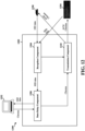
- FIG. 12 is a conceptual data flow diagram 1200 illustrating the data flow between different means/components in an exemplary apparatus 1202.
- the apparatus 1202 may be a dongle (e.g., the dongle 158 or 1002).
- the apparatus 1202 may include a reception component 1204 that receives HID data from HID devices 1250 (e.g., a wireless mouse) and 1254 (e.g., a wireless keyboard).
- HID devices 1250 e.g., a wireless mouse
- 1254 e.g., a wireless keyboard
- the reception component 1204 may perform the operations described above with reference to 1102 or 1106 in FIG. 11 .
- the apparatus 1202 may include a transmission component 1210 that transmits ACK and Chroma data to HID device 1250 and/or 1254.
- the transmission component 1210 may perform the operations described above with reference to 1110 in FIG. 11 .
- the reception component 1204 and the transmission component 1210 may collaborate to coordinate the communication of the apparatus 1202.
- the apparatus 1202 may include a data relay component 1206 that is configured to relay HID data from the reception component 1204 to a computing device 1252.
- the relay component 1206 may be further configured to relay Chroma data from the computing device 1252 to the transmission component 1210.
- the data relay component 1206 may perform the operations described above with reference to 1104 or 1108 in FIG. 11 .
- the apparatus 1202 may include additional components that perform each of the blocks of the algorithm in the aforementioned flowcharts of FIGS. 3-5 and 11 .
- each block in the aforementioned flowcharts of FIGS. 3-5 and 11 may be performed by a component and the apparatus may include one or more of those components.
- the components may be one or more hardware components specifically configured to carry out the stated processes/algorithm, implemented by a processor configured to perform the stated processes/algorithm, stored within a computer-readable medium for implementation by a processor, or some combination thereof.
- FIG. 13 is a diagram 1300 illustrating an example of a hardware implementation for an apparatus 1202' employing a processing system 1314.
- the apparatus 1202' may be the apparatus 1202 described above with reference to FIG. 12 .
- the processing system 1314 may be implemented with a bus architecture, represented generally by the bus 1324.
- the bus 1324 may include any number of interconnecting buses and bridges depending on the specific application of the processing system 1314 and the overall design constraints.
- the bus 1324 links together various circuits including one or more processors and/or hardware components, represented by the processor 1304, the components 1204, 1206, 1210, and the computer-readable medium / memory 1306.
- the bus 1324 may also link various other circuits such as timing sources, peripherals, voltage regulators, and power management circuits, which are well known in the art, and therefore, will not be described any further.
- the processing system 1314 may be coupled to a transceiver 1310.
- the transceiver 1310 is coupled to one or more antennas 1320.
- the transceiver 1310 provides a means for communicating with various other apparatus over a transmission medium.
- the transceiver 1310 receives a signal from the one or more antennas 1320, extracts information from the received signal, and provides the extracted information to the processing system 1314, specifically the reception component 1204.
- the transceiver 1310 receives information from the processing system 1314, specifically the transmission component 1210, and based on the received information, generates a signal to be applied to the one or more antennas 1320.
- the processing system 1314 includes a processor 1304 coupled to a computer-readable medium / memory 1306.
- the processor 1304 is responsible for general processing, including the analyzation of data gathered by the apparatus itself through its own sensors and the execution of software stored on the computer-readable medium / memory 1306.
- the software when executed by the processor 1304, causes the processing system 1314 to perform the various functions described supra for any particular apparatus.
- the computer-readable medium / memory 1306 may also be used for storing data that is manipulated by the processor 1304 when executing software.
- the processing system 1314 further includes at least one of the components 1204, 1206, 1210.
- the components may be software components running in the processor 1304, resident/stored in the computer readable medium / memory 1306, one or more hardware components coupled to the processor 1304, or some combination thereof.
Landscapes
- Engineering & Computer Science (AREA)
- Theoretical Computer Science (AREA)
- General Engineering & Computer Science (AREA)
- Physics & Mathematics (AREA)
- General Physics & Mathematics (AREA)
- Human Computer Interaction (AREA)
- Computer Networks & Wireless Communication (AREA)
- Mobile Radio Communication Systems (AREA)
- Position Input By Displaying (AREA)
- User Interface Of Digital Computer (AREA)
Claims (15)
- Ein Verfahren (1100) zur Drahtlos-Kommunikation, wobei das Verfahren aufweist:Empfangen (1102) von ersten Daten von einer ersten Menschliche-Schnittstelle-Vorrichtung an einem Dongle über einen Funkfrequenzkanal in einem ersten Zeitschlitz eines Frames;Übertragen (1104) der ersten Daten an eine mit dem Dongle gekoppelte Rechenvorrichtung;Empfangen (1106) von zweiten Daten von einer zweiten Menschliche-Schnittstelle-Vorrichtung an dem Dongle über den Funkfrequenzkanal in einem zweiten Zeitschlitz des Frames;Übertragen (1108) der zweiten Daten an die Rechenvorrichtung; undÜbertragen (1110), durch den Dongle über den Funkfrequenzkanal in einem dritten Zeitschlitz des Frames, einer ersten Bestätigung der ersten Daten und erster Beleuchtungseffekt-Konfigurationsdaten für die erste Menschliche-Schnittstelle-Vorrichtung, einer zweiten Bestätigung der zweiten Daten und zweiter Beleuchtungseffekt-Konfigurationsdaten für die zweite Menschliche-Schnittstelle-Vorrichtung.
- Das Verfahren (1100) nach Anspruch 1, wobei die erste Menschliche-Schnittstelle-Vorrichtung und die zweite Menschliche-Schnittstelle-Vorrichtung eine drahtlose Maus und eine drahtlose Tastatur sind.
- Das Verfahren (1100) nach Anspruch 2, wobei die ersten Daten einen Bewegungs- und Tastenzustand der drahtlosen Maus aufweisen; und/oder
wobei die zweiten Daten den Tastendrückstatus der drahtlosen Tastatur aufweist. - Das Verfahren (1100) nach irgendeinem der Ansprüche 1 bis 3, wobei die ersten Beleuchtungseffekt-Konfigurationsdaten verwendet werden, um den Beleuchtungseffekt der ersten Menschliche-Schnittstelle-Vorrichtung zu konfigurieren.
- Das Verfahren (1100) nach irgendeinem der Ansprüche 1 bis 4, bei dem die zweiten Beleuchtungseffekt-Konfigurationsdaten dazu verwendet werden, den Beleuchtungseffekt der zweiten Menschliche-Schnittstelle-Vorrichtung zu konfigurieren.
- Das Verfahren (1100) nach irgendeinem der Ansprüche 1 bis 5, bei dem sowohl die erste Menschliche-Schnittstelle-Vorrichtung als auch die zweite Menschliche-Schnittstelle-Vorrichtung mit dem Dongle synchronisiert sind.
- Das Verfahren (1100) nach irgendeinem der Ansprüche 1 bis 6, ferner aufweisend:Senden (308) eines ersten Leitstrahls durch den Dongle im ersten Zeitschlitz, um sich mit der ersten Menschliche-Schnittstelle-Vorrichtung zu synchronisieren; undSenden (410) eines zweiten Leitstrahls durch den Dongle in dem zweiten Zeitschlitz, um sich mit der zweiten Menschliche-Schnittstelle-Vorrichtung zu synchronisieren.
- Ein Gerät (1202, 1202') zur Drahtlos-Kommunikation, wobei das Gerät aufweist:einen Speicher (1306); undmindestens einen Prozessor (1304), der mit dem Speicher (1306) gekoppelt und eingerichtet ist zum:Empfangen erster Daten von einer ersten Menschliche-Schnittstelle-Vorrichtung, die mit dem Gerät in einem ersten Zeitschlitz eines Frames synchronisiert ist, durch das Gerät über einen Funkfrequenzkanal;Übertragen der ersten Daten durch das Gerät an eine mit dem Gerät gekoppelte Rechenvorrichtung;Empfangen von zweiten Daten von einer zweiten Menschliche-Schnittstelle-Vorrichtung, die mit dem Gerät in einem zweiten Zeitschlitz des Frames synchronisiert ist, durch das Gerät über den Funkfrequenzkanal;Übertragen der zweiten Daten durch das Gerät an die Rechenvorrichtung; undÜbertragen einer ersten Bestätigung der ersten Daten und erster Beleuchtungseffekt-Konfigurationsdaten für die erste Menschliche-Schnittstelle-Vorrichtung, einer zweiten Bestätigung der zweiten Daten und zweiter Beleuchtungseffekt-Konfigurationsdaten für die zweite Menschliche-Schnittstelle-Vorrichtung durch das Gerät über den Funkfrequenzkanal in einem dritten Zeitschlitz des Frames .
- Das Gerät (1202, 1202') nach Anspruch 8, wobei die erste Menschliche-Schnittstelle-Vorrichtung und die zweite Menschliche-Schnittstelle-Vorrichtung eine drahtlose Maus und eine drahtlose Tastatur sind.
- Das Gerät (1202, 1202') nach Anspruch 9, wobei die ersten Daten den Bewegungs- und Tastenstatus der drahtlosen Maus aufweisen; und/oder
wobei die zweiten Daten den Tastendrückstatus der drahtlosen Tastatur aufweist. - Das Gerät (1202, 1202') nach irgendeinem der Ansprüche 8 bis 10, wobei die ersten Beleuchtungseffekt-Konfigurationsdaten verwendet werden, um den Beleuchtungseffekt der ersten Menschliche-Schnittstelle-Vorrichtung zu konfigurieren; und/oder wobei die zweiten Beleuchtungseffekt-Konfigurationsdaten verwendet werden, um den Beleuchtungseffekt der zweiten Menschliche-Schnittstelle-Vorrichtung zu konfigurieren.
- Das Gerät (1202, 1202') nach irgendeinem der Ansprüche 8 bis 11, wobei der mindestens eine Prozessor ferner eingerichtet ist, um:durch das Gerät in dem ersten Zeitschlitz einen ersten Leitstrahl zu senden, um sich mit der ersten menschlichen Schnittstellenvorrichtung zu synchronisieren; unddurch das Gerät in dem zweiten Zeitschlitz einen zweiten Leitstrahl zu senden, um sich mit der zweiten Menschliche-Schnittstelle-Vorrichtung zu synchronisieren.
- Ein nicht-flüchtiges computerlesbares Medium, das einen computerausführbaren Code speichert, der Anweisungen aufweist zum:Empfangen (1102) von ersten Daten von einer ersten Menschliche-Schnittstelle-Vorrichtung in einem ersten Zeitschlitz eines Frames an einem Dongle über einen Funkfrequenzkanal;Übertragen (1104) der ersten Daten an eine mit dem Dongle gekoppelte Rechenvorrichtung;Empfangen (1106) von zweiten Daten von einer zweiten Menschliche-Schnittstelle-Vorrichtung an dem Dongle über den Funkfrequenzkanal in einem zweiten Zeitschlitz des Frames;Übertragen (1108) der zweiten Daten an die Vorrichtung; undÜbertragen (1110), durch den Dongle über den Funkfrequenzkanal in einem dritten Zeitschlitz des Frames, einer ersten Bestätigung der ersten Daten und erster Beleuchtungseffekt-Konfigurationsdaten für die erste Menschliche-Schnittstelle-Vorrichtung, einer zweiten Bestätigung der zweiten Daten und zweiter Beleuchtungseffekt-Konfigurationsdaten für die zweite Menschliche-Schnittstelle-Vorrichtung.
- Das nicht-flüchtige computerlesbare Medium nach Anspruch 13, wobei die erste Menschliche-Schnittstelle-Vorrichtung und die zweite Menschliche-Schnittstelle-Vorrichtung eine drahtlose Maus und eine drahtlose Tastatur sind;
wobei die ersten Daten einen Bewegungs- und Tastenstatus der drahtlosen Maus aufweisen, wobei die zweiten Daten einen Tastendruckstatus der drahtlosen Tastatur aufweisen. - Das nicht-flüchtige computerlesbare Medium nach irgendeinem der Ansprüche 13 bis 14, wobei die ersten Beleuchtungseffekt-Konfigurationsdaten verwendet werden, um den Beleuchtungseffekt der ersten Menschliche-Schnittstelle-Vorrichtung zu konfigurieren, wobei die zweiten Beleuchtungseffekt-Konfigurationsdaten verwendet werden, um den Beleuchtungseffekt der zweiten Menschliche-Schnittstelle-Vorrichtung zu konfigurieren.
Applications Claiming Priority (1)
| Application Number | Priority Date | Filing Date | Title |
|---|---|---|---|
| PCT/SG2018/050361 WO2020022950A1 (en) | 2018-07-23 | 2018-07-23 | A wireless lighting effect configuration data transmission system |
Publications (3)
| Publication Number | Publication Date |
|---|---|
| EP3827353A1 EP3827353A1 (de) | 2021-06-02 |
| EP3827353A4 EP3827353A4 (de) | 2021-07-28 |
| EP3827353B1 true EP3827353B1 (de) | 2023-04-19 |
Family
ID=69181775
Family Applications (1)
| Application Number | Title | Priority Date | Filing Date |
|---|---|---|---|
| EP18928114.0A Active EP3827353B1 (de) | 2018-07-23 | 2018-07-23 | Datenübertragungssystem mit drahtloser beleuchtung |
Country Status (7)
| Country | Link |
|---|---|
| US (4) | US11429210B2 (de) |
| EP (1) | EP3827353B1 (de) |
| CN (1) | CN112424761B (de) |
| AU (1) | AU2018433605B2 (de) |
| SG (1) | SG11202012971PA (de) |
| TW (1) | TWI826480B (de) |
| WO (1) | WO2020022950A1 (de) |
Families Citing this family (6)
| Publication number | Priority date | Publication date | Assignee | Title |
|---|---|---|---|---|
| US12380045B2 (en) * | 2021-11-26 | 2025-08-05 | Razer (Asia-Pacific) Pte. Ltd. | System and method for facilitating data communication |
| WO2023096568A1 (en) * | 2021-11-26 | 2023-06-01 | Razer (Asia-Pacific) Pte. Ltd. | System and method for facilitating data communication |
| CN119631062A (zh) * | 2022-08-19 | 2025-03-14 | 雷蛇(亚太)私人有限公司 | 用于促进数据通信的系统及方法 |
| CN118102487A (zh) * | 2022-11-18 | 2024-05-28 | 华为技术有限公司 | 一种数据显示方法、系统和电子设备 |
| US20250039931A1 (en) * | 2023-07-30 | 2025-01-30 | Dell Products, Lp | System and method for collision-free joining of wireless input/output (io) devices to a wireless io device network |
| WO2025244575A1 (en) * | 2024-05-24 | 2025-11-27 | Razer (Asia-Pacific) Pte. Ltd. | A method for wireless communication between a receiver and one or more computer peripheral devices and a receiver |
Family Cites Families (15)
| Publication number | Priority date | Publication date | Assignee | Title |
|---|---|---|---|---|
| JPH05119899A (ja) * | 1991-08-30 | 1993-05-18 | I Denshi Sokki Kk | ポータブルコンピユータのためのキーボード接続システム |
| JP2638488B2 (ja) * | 1994-07-22 | 1997-08-06 | 日本電気株式会社 | ワイヤレスキーボード |
| US5881366A (en) | 1996-05-01 | 1999-03-09 | Logitech, Inc. | Wireless peripheral interface |
| US7015833B1 (en) * | 2000-08-31 | 2006-03-21 | Logitech Europe S.A. | Multilink receiver for multiple cordless applications |
| US7024501B1 (en) * | 2002-11-18 | 2006-04-04 | Cypress Semiconductor Corp. | Method and apparatus for attaching USB peripherals to host ports |
| US7433697B2 (en) * | 2003-10-24 | 2008-10-07 | Broadcom Corporation | Synchronized UWB piconets for Simultaneously Operating Piconet performance |
| US20050243059A1 (en) * | 2004-03-16 | 2005-11-03 | Morris Martin G | High-reliability computer interface for wireless input devices |
| US8207937B2 (en) * | 2005-06-24 | 2012-06-26 | Logitech Europe S.A. | Communication protocol for networked devices |
| US7480268B2 (en) | 2005-07-28 | 2009-01-20 | Symbol Technologies, Inc. | System and method for multiprotocol wireless communication |
| US8024500B2 (en) | 2005-08-15 | 2011-09-20 | Research In Motion Limited | Universal peripheral connector |
| KR100871854B1 (ko) * | 2006-06-05 | 2008-12-03 | 삼성전자주식회사 | 비동기 데이터 전송을 위한 채널 할당 관리 방법, 비동기데이터 전송 방법 및 상기 방법을 이용하는 장치 |
| US20080175190A1 (en) * | 2007-01-08 | 2008-07-24 | Freesystems Pte., Ltd. | Multi-node media content distribution system |
| KR20130101975A (ko) * | 2010-04-16 | 2013-09-16 | 니콜라스 제이 마스탄드리아 | 착용형 모션 감지 컴퓨팅 인터페이스 |
| KR20120069262A (ko) | 2010-12-20 | 2012-06-28 | 삼성전자주식회사 | 외부 입력 수단 운용을 위한 동글 장치와 이를 포함하는 외부 입력 시스템 및 운용 방법 |
| US8832322B2 (en) * | 2012-01-20 | 2014-09-09 | Plantronics, Inc. | Online indicator adapter |
-
2018
- 2018-07-23 EP EP18928114.0A patent/EP3827353B1/de active Active
- 2018-07-23 US US17/260,972 patent/US11429210B2/en active Active
- 2018-07-23 CN CN201880095593.0A patent/CN112424761B/zh active Active
- 2018-07-23 SG SG11202012971PA patent/SG11202012971PA/en unknown
- 2018-07-23 WO PCT/SG2018/050361 patent/WO2020022950A1/en not_active Ceased
- 2018-07-23 AU AU2018433605A patent/AU2018433605B2/en active Active
-
2019
- 2019-07-04 TW TW108123528A patent/TWI826480B/zh active
-
2022
- 2022-07-14 US US17/865,310 patent/US11836306B2/en active Active
-
2023
- 2023-10-18 US US18/489,766 patent/US12386441B2/en active Active
-
2025
- 2025-07-15 US US19/269,130 patent/US20250341904A1/en active Pending
Also Published As
| Publication number | Publication date |
|---|---|
| CN112424761A (zh) | 2021-02-26 |
| AU2018433605A1 (en) | 2021-03-11 |
| EP3827353A1 (de) | 2021-06-02 |
| EP3827353A4 (de) | 2021-07-28 |
| TWI826480B (zh) | 2023-12-21 |
| US11429210B2 (en) | 2022-08-30 |
| WO2020022950A1 (en) | 2020-01-30 |
| CN112424761B (zh) | 2024-08-09 |
| US20210318762A1 (en) | 2021-10-14 |
| TW202008761A (zh) | 2020-02-16 |
| US12386441B2 (en) | 2025-08-12 |
| US11836306B2 (en) | 2023-12-05 |
| AU2018433605B2 (en) | 2024-02-22 |
| US20240045524A1 (en) | 2024-02-08 |
| US20220350425A1 (en) | 2022-11-03 |
| US20250341904A1 (en) | 2025-11-06 |
| SG11202012971PA (en) | 2021-01-28 |
Similar Documents
| Publication | Publication Date | Title |
|---|---|---|
| US12386441B2 (en) | Wireless lighting effect configuration data transmission system | |
| CN105744636B (zh) | 地面站及地面站与无人机的通信方法 | |
| CN107015927B (zh) | 一种基于SoC支持多个SPI接口标准组的装置 | |
| CN204652678U (zh) | 一种智能家庭控制网关 | |
| KR101706876B1 (ko) | 서비스 처리 방법 및 장치 | |
| EP2822352B1 (de) | Drahtloses Steuerungssystem und darauf angewandtes drahtloses Netzwerkerweiterungsverfahren | |
| US20220124841A1 (en) | Human machine interface for mission critical wireless communication link nodes | |
| US9467222B1 (en) | Systems and methods for parallel communication with multiple bluetooth devices | |
| AU2007320830B2 (en) | Device for controlling a computer system | |
| CN105068435A (zh) | 一种分布式无线智能家居系统 | |
| KR102311131B1 (ko) | 단말기, 조명 기구, 정보 단말, 페어링 방법 및 프로그램 | |
| US12056069B2 (en) | Method and apparatus for optimizing input latency in a wireless human interface device system | |
| CN206133900U (zh) | 基于蓝牙广播信号的设备控制系统 | |
| CN103778771A (zh) | 一种便携式无线输入输出设备收发器及其使用方法 | |
| WO2023011309A1 (zh) | 反馈方法、相关设备及可读存储介质 | |
| US20150282193A1 (en) | Method and apparatus for avoiding communication interference in wireless communication system | |
| US10517162B2 (en) | Lighting system and communication terminal | |
| EP3016433A1 (de) | Drahtlose kommunikationsvorrichtung, drahtloses kommunikationssystem, computerlesbares aufzeichnungsmedium und drahtloses kommunikationsverfahren | |
| KR20180129158A (ko) | Sdr 기술을 수행하는 이동 단말 및 이의 제어 방법 | |
| CN119654611A (zh) | 数据传输方法及装置 | |
| KR20140089864A (ko) | 인터페이스 장치 및 이를 이용한 단말기와 컴퓨터의 연동 시스템 | |
| CN105228097A (zh) | 一种应用于信号源的室内无线远控方法 | |
| JP2023086985A5 (ja) | ビーコン利用方法 | |
| CN116357907A (zh) | 一种室内照明装置 | |
| KR20080020788A (ko) | 무선 usb를 이용한 특정 파일의 멀티 다운로드 기능을구비한 시스템 및 그 제어방법 |
Legal Events
| Date | Code | Title | Description |
|---|---|---|---|
| STAA | Information on the status of an ep patent application or granted ep patent |
Free format text: STATUS: THE INTERNATIONAL PUBLICATION HAS BEEN MADE |
|
| PUAI | Public reference made under article 153(3) epc to a published international application that has entered the european phase |
Free format text: ORIGINAL CODE: 0009012 |
|
| STAA | Information on the status of an ep patent application or granted ep patent |
Free format text: STATUS: REQUEST FOR EXAMINATION WAS MADE |
|
| 17P | Request for examination filed |
Effective date: 20210104 |
|
| AK | Designated contracting states |
Kind code of ref document: A1 Designated state(s): AL AT BE BG CH CY CZ DE DK EE ES FI FR GB GR HR HU IE IS IT LI LT LU LV MC MK MT NL NO PL PT RO RS SE SI SK SM TR |
|
| A4 | Supplementary search report drawn up and despatched |
Effective date: 20210625 |
|
| RIC1 | Information provided on ipc code assigned before grant |
Ipc: G06F 3/02 20060101ALI20210621BHEP Ipc: G06F 3/038 20130101ALI20210621BHEP Ipc: G06F 3/0354 20130101ALI20210621BHEP Ipc: H05B 45/20 20200101ALI20210621BHEP Ipc: H04B 7/26 20060101ALI20210621BHEP Ipc: G06F 3/033 20130101ALI20210621BHEP Ipc: G06F 3/023 20060101ALI20210621BHEP Ipc: G06F 13/10 20060101AFI20210621BHEP |
|
| RAP3 | Party data changed (applicant data changed or rights of an application transferred) |
Owner name: RAZER (ASIA-PACIFIC) PTE. LTD. |
|
| DAV | Request for validation of the european patent (deleted) | ||
| DAX | Request for extension of the european patent (deleted) | ||
| GRAP | Despatch of communication of intention to grant a patent |
Free format text: ORIGINAL CODE: EPIDOSNIGR1 |
|
| RIC1 | Information provided on ipc code assigned before grant |
Ipc: H05B 47/19 20200101ALI20221018BHEP Ipc: G06F 3/023 20060101ALI20221018BHEP Ipc: G06F 3/033 20130101ALI20221018BHEP Ipc: H04B 7/26 20060101ALI20221018BHEP Ipc: H05B 45/20 20200101ALI20221018BHEP Ipc: G06F 3/0354 20130101ALI20221018BHEP Ipc: G06F 3/038 20130101ALI20221018BHEP Ipc: G06F 3/02 20060101ALI20221018BHEP Ipc: G06F 13/10 20060101AFI20221018BHEP |
|
| STAA | Information on the status of an ep patent application or granted ep patent |
Free format text: STATUS: GRANT OF PATENT IS INTENDED |
|
| INTG | Intention to grant announced |
Effective date: 20221124 |
|
| GRAS | Grant fee paid |
Free format text: ORIGINAL CODE: EPIDOSNIGR3 |
|
| GRAA | (expected) grant |
Free format text: ORIGINAL CODE: 0009210 |
|
| STAA | Information on the status of an ep patent application or granted ep patent |
Free format text: STATUS: THE PATENT HAS BEEN GRANTED |
|
| AK | Designated contracting states |
Kind code of ref document: B1 Designated state(s): AL AT BE BG CH CY CZ DE DK EE ES FI FR GB GR HR HU IE IS IT LI LT LU LV MC MK MT NL NO PL PT RO RS SE SI SK SM TR |
|
| REG | Reference to a national code |
Ref country code: GB Ref legal event code: FG4D |
|
| REG | Reference to a national code |
Ref country code: CH Ref legal event code: EP |
|
| REG | Reference to a national code |
Ref country code: DE Ref legal event code: R096 Ref document number: 602018048777 Country of ref document: DE |
|
| REG | Reference to a national code |
Ref country code: IE Ref legal event code: FG4D |
|
| REG | Reference to a national code |
Ref country code: AT Ref legal event code: REF Ref document number: 1561726 Country of ref document: AT Kind code of ref document: T Effective date: 20230515 |
|
| P01 | Opt-out of the competence of the unified patent court (upc) registered |
Effective date: 20230327 |
|
| REG | Reference to a national code |
Ref country code: LT Ref legal event code: MG9D |
|
| REG | Reference to a national code |
Ref country code: NL Ref legal event code: MP Effective date: 20230419 |
|
| REG | Reference to a national code |
Ref country code: AT Ref legal event code: MK05 Ref document number: 1561726 Country of ref document: AT Kind code of ref document: T Effective date: 20230419 |
|
| PG25 | Lapsed in a contracting state [announced via postgrant information from national office to epo] |
Ref country code: NL Free format text: LAPSE BECAUSE OF FAILURE TO SUBMIT A TRANSLATION OF THE DESCRIPTION OR TO PAY THE FEE WITHIN THE PRESCRIBED TIME-LIMIT Effective date: 20230419 |
|
| PG25 | Lapsed in a contracting state [announced via postgrant information from national office to epo] |
Ref country code: SE Free format text: LAPSE BECAUSE OF FAILURE TO SUBMIT A TRANSLATION OF THE DESCRIPTION OR TO PAY THE FEE WITHIN THE PRESCRIBED TIME-LIMIT Effective date: 20230419 Ref country code: PT Free format text: LAPSE BECAUSE OF FAILURE TO SUBMIT A TRANSLATION OF THE DESCRIPTION OR TO PAY THE FEE WITHIN THE PRESCRIBED TIME-LIMIT Effective date: 20230821 Ref country code: NO Free format text: LAPSE BECAUSE OF FAILURE TO SUBMIT A TRANSLATION OF THE DESCRIPTION OR TO PAY THE FEE WITHIN THE PRESCRIBED TIME-LIMIT Effective date: 20230719 Ref country code: ES Free format text: LAPSE BECAUSE OF FAILURE TO SUBMIT A TRANSLATION OF THE DESCRIPTION OR TO PAY THE FEE WITHIN THE PRESCRIBED TIME-LIMIT Effective date: 20230419 Ref country code: AT Free format text: LAPSE BECAUSE OF FAILURE TO SUBMIT A TRANSLATION OF THE DESCRIPTION OR TO PAY THE FEE WITHIN THE PRESCRIBED TIME-LIMIT Effective date: 20230419 |
|
| PG25 | Lapsed in a contracting state [announced via postgrant information from national office to epo] |
Ref country code: RS Free format text: LAPSE BECAUSE OF FAILURE TO SUBMIT A TRANSLATION OF THE DESCRIPTION OR TO PAY THE FEE WITHIN THE PRESCRIBED TIME-LIMIT Effective date: 20230419 Ref country code: PL Free format text: LAPSE BECAUSE OF FAILURE TO SUBMIT A TRANSLATION OF THE DESCRIPTION OR TO PAY THE FEE WITHIN THE PRESCRIBED TIME-LIMIT Effective date: 20230419 Ref country code: LV Free format text: LAPSE BECAUSE OF FAILURE TO SUBMIT A TRANSLATION OF THE DESCRIPTION OR TO PAY THE FEE WITHIN THE PRESCRIBED TIME-LIMIT Effective date: 20230419 Ref country code: LT Free format text: LAPSE BECAUSE OF FAILURE TO SUBMIT A TRANSLATION OF THE DESCRIPTION OR TO PAY THE FEE WITHIN THE PRESCRIBED TIME-LIMIT Effective date: 20230419 Ref country code: IS Free format text: LAPSE BECAUSE OF FAILURE TO SUBMIT A TRANSLATION OF THE DESCRIPTION OR TO PAY THE FEE WITHIN THE PRESCRIBED TIME-LIMIT Effective date: 20230819 Ref country code: HR Free format text: LAPSE BECAUSE OF FAILURE TO SUBMIT A TRANSLATION OF THE DESCRIPTION OR TO PAY THE FEE WITHIN THE PRESCRIBED TIME-LIMIT Effective date: 20230419 Ref country code: GR Free format text: LAPSE BECAUSE OF FAILURE TO SUBMIT A TRANSLATION OF THE DESCRIPTION OR TO PAY THE FEE WITHIN THE PRESCRIBED TIME-LIMIT Effective date: 20230720 Ref country code: AL Free format text: LAPSE BECAUSE OF FAILURE TO SUBMIT A TRANSLATION OF THE DESCRIPTION OR TO PAY THE FEE WITHIN THE PRESCRIBED TIME-LIMIT Effective date: 20230419 |
|
| PG25 | Lapsed in a contracting state [announced via postgrant information from national office to epo] |
Ref country code: FI Free format text: LAPSE BECAUSE OF FAILURE TO SUBMIT A TRANSLATION OF THE DESCRIPTION OR TO PAY THE FEE WITHIN THE PRESCRIBED TIME-LIMIT Effective date: 20230419 |
|
| PG25 | Lapsed in a contracting state [announced via postgrant information from national office to epo] |
Ref country code: SK Free format text: LAPSE BECAUSE OF FAILURE TO SUBMIT A TRANSLATION OF THE DESCRIPTION OR TO PAY THE FEE WITHIN THE PRESCRIBED TIME-LIMIT Effective date: 20230419 |
|
| REG | Reference to a national code |
Ref country code: DE Ref legal event code: R097 Ref document number: 602018048777 Country of ref document: DE |
|
| PG25 | Lapsed in a contracting state [announced via postgrant information from national office to epo] |
Ref country code: SM Free format text: LAPSE BECAUSE OF FAILURE TO SUBMIT A TRANSLATION OF THE DESCRIPTION OR TO PAY THE FEE WITHIN THE PRESCRIBED TIME-LIMIT Effective date: 20230419 Ref country code: SK Free format text: LAPSE BECAUSE OF FAILURE TO SUBMIT A TRANSLATION OF THE DESCRIPTION OR TO PAY THE FEE WITHIN THE PRESCRIBED TIME-LIMIT Effective date: 20230419 Ref country code: RO Free format text: LAPSE BECAUSE OF FAILURE TO SUBMIT A TRANSLATION OF THE DESCRIPTION OR TO PAY THE FEE WITHIN THE PRESCRIBED TIME-LIMIT Effective date: 20230419 Ref country code: EE Free format text: LAPSE BECAUSE OF FAILURE TO SUBMIT A TRANSLATION OF THE DESCRIPTION OR TO PAY THE FEE WITHIN THE PRESCRIBED TIME-LIMIT Effective date: 20230419 Ref country code: DK Free format text: LAPSE BECAUSE OF FAILURE TO SUBMIT A TRANSLATION OF THE DESCRIPTION OR TO PAY THE FEE WITHIN THE PRESCRIBED TIME-LIMIT Effective date: 20230419 Ref country code: CZ Free format text: LAPSE BECAUSE OF FAILURE TO SUBMIT A TRANSLATION OF THE DESCRIPTION OR TO PAY THE FEE WITHIN THE PRESCRIBED TIME-LIMIT Effective date: 20230419 |
|
| PLBE | No opposition filed within time limit |
Free format text: ORIGINAL CODE: 0009261 |
|
| STAA | Information on the status of an ep patent application or granted ep patent |
Free format text: STATUS: NO OPPOSITION FILED WITHIN TIME LIMIT |
|
| PG25 | Lapsed in a contracting state [announced via postgrant information from national office to epo] |
Ref country code: MC Free format text: LAPSE BECAUSE OF FAILURE TO SUBMIT A TRANSLATION OF THE DESCRIPTION OR TO PAY THE FEE WITHIN THE PRESCRIBED TIME-LIMIT Effective date: 20230419 |
|
| PG25 | Lapsed in a contracting state [announced via postgrant information from national office to epo] |
Ref country code: MC Free format text: LAPSE BECAUSE OF FAILURE TO SUBMIT A TRANSLATION OF THE DESCRIPTION OR TO PAY THE FEE WITHIN THE PRESCRIBED TIME-LIMIT Effective date: 20230419 |
|
| REG | Reference to a national code |
Ref country code: CH Ref legal event code: PL |
|
| REG | Reference to a national code |
Ref country code: BE Ref legal event code: MM Effective date: 20230731 |
|
| PG25 | Lapsed in a contracting state [announced via postgrant information from national office to epo] |
Ref country code: LU Free format text: LAPSE BECAUSE OF NON-PAYMENT OF DUE FEES Effective date: 20230723 |
|
| 26N | No opposition filed |
Effective date: 20240122 |
|
| PG25 | Lapsed in a contracting state [announced via postgrant information from national office to epo] |
Ref country code: LU Free format text: LAPSE BECAUSE OF NON-PAYMENT OF DUE FEES Effective date: 20230723 |
|
| REG | Reference to a national code |
Ref country code: IE Ref legal event code: MM4A |
|
| PG25 | Lapsed in a contracting state [announced via postgrant information from national office to epo] |
Ref country code: CH Free format text: LAPSE BECAUSE OF NON-PAYMENT OF DUE FEES Effective date: 20230731 |
|
| PG25 | Lapsed in a contracting state [announced via postgrant information from national office to epo] |
Ref country code: SI Free format text: LAPSE BECAUSE OF FAILURE TO SUBMIT A TRANSLATION OF THE DESCRIPTION OR TO PAY THE FEE WITHIN THE PRESCRIBED TIME-LIMIT Effective date: 20230419 |
|
| PG25 | Lapsed in a contracting state [announced via postgrant information from national office to epo] |
Ref country code: SI Free format text: LAPSE BECAUSE OF FAILURE TO SUBMIT A TRANSLATION OF THE DESCRIPTION OR TO PAY THE FEE WITHIN THE PRESCRIBED TIME-LIMIT Effective date: 20230419 Ref country code: IT Free format text: LAPSE BECAUSE OF FAILURE TO SUBMIT A TRANSLATION OF THE DESCRIPTION OR TO PAY THE FEE WITHIN THE PRESCRIBED TIME-LIMIT Effective date: 20230419 Ref country code: BE Free format text: LAPSE BECAUSE OF NON-PAYMENT OF DUE FEES Effective date: 20230731 |
|
| PG25 | Lapsed in a contracting state [announced via postgrant information from national office to epo] |
Ref country code: IE Free format text: LAPSE BECAUSE OF NON-PAYMENT OF DUE FEES Effective date: 20230723 |
|
| PG25 | Lapsed in a contracting state [announced via postgrant information from national office to epo] |
Ref country code: IE Free format text: LAPSE BECAUSE OF NON-PAYMENT OF DUE FEES Effective date: 20230723 |
|
| PG25 | Lapsed in a contracting state [announced via postgrant information from national office to epo] |
Ref country code: BG Free format text: LAPSE BECAUSE OF FAILURE TO SUBMIT A TRANSLATION OF THE DESCRIPTION OR TO PAY THE FEE WITHIN THE PRESCRIBED TIME-LIMIT Effective date: 20230419 |
|
| PG25 | Lapsed in a contracting state [announced via postgrant information from national office to epo] |
Ref country code: BG Free format text: LAPSE BECAUSE OF FAILURE TO SUBMIT A TRANSLATION OF THE DESCRIPTION OR TO PAY THE FEE WITHIN THE PRESCRIBED TIME-LIMIT Effective date: 20230419 |
|
| PG25 | Lapsed in a contracting state [announced via postgrant information from national office to epo] |
Ref country code: CY Free format text: LAPSE BECAUSE OF FAILURE TO SUBMIT A TRANSLATION OF THE DESCRIPTION OR TO PAY THE FEE WITHIN THE PRESCRIBED TIME-LIMIT; INVALID AB INITIO Effective date: 20180723 |
|
| PG25 | Lapsed in a contracting state [announced via postgrant information from national office to epo] |
Ref country code: HU Free format text: LAPSE BECAUSE OF FAILURE TO SUBMIT A TRANSLATION OF THE DESCRIPTION OR TO PAY THE FEE WITHIN THE PRESCRIBED TIME-LIMIT; INVALID AB INITIO Effective date: 20180723 |
|
| PGFP | Annual fee paid to national office [announced via postgrant information from national office to epo] |
Ref country code: DE Payment date: 20250611 Year of fee payment: 8 |
|
| PG25 | Lapsed in a contracting state [announced via postgrant information from national office to epo] |
Ref country code: TR Free format text: LAPSE BECAUSE OF FAILURE TO SUBMIT A TRANSLATION OF THE DESCRIPTION OR TO PAY THE FEE WITHIN THE PRESCRIBED TIME-LIMIT Effective date: 20230419 |
|
| PGFP | Annual fee paid to national office [announced via postgrant information from national office to epo] |
Ref country code: GB Payment date: 20260608 Year of fee payment: 9 |
|
| PGFP | Annual fee paid to national office [announced via postgrant information from national office to epo] |
Ref country code: FR Payment date: 20260608 Year of fee payment: 9 |