EP3827704A1 - Verbindungsstruktur zwischen füssen und mittelteil, füsse, mittelteil, gestell und stuhl - Google Patents
Verbindungsstruktur zwischen füssen und mittelteil, füsse, mittelteil, gestell und stuhl Download PDFInfo
- Publication number
- EP3827704A1 EP3827704A1 EP20844070.1A EP20844070A EP3827704A1 EP 3827704 A1 EP3827704 A1 EP 3827704A1 EP 20844070 A EP20844070 A EP 20844070A EP 3827704 A1 EP3827704 A1 EP 3827704A1
- Authority
- EP
- European Patent Office
- Prior art keywords
- center piece
- rotation limit
- support feet
- connecting portion
- hook
- Prior art date
- Legal status (The legal status is an assumption and is not a legal conclusion. Google has not performed a legal analysis and makes no representation as to the accuracy of the status listed.)
- Granted
Links
Images




Classifications
-
- A—HUMAN NECESSITIES
- A47—FURNITURE; DOMESTIC ARTICLES OR APPLIANCES; COFFEE MILLS; SPICE MILLS; SUCTION CLEANERS IN GENERAL
- A47C—CHAIRS; SOFAS; BEDS
- A47C7/00—Parts, details, or accessories of chairs or stools
- A47C7/002—Chair or stool bases
-
- A—HUMAN NECESSITIES
- A47—FURNITURE; DOMESTIC ARTICLES OR APPLIANCES; COFFEE MILLS; SPICE MILLS; SUCTION CLEANERS IN GENERAL
- A47C—CHAIRS; SOFAS; BEDS
- A47C7/00—Parts, details, or accessories of chairs or stools
- A47C7/002—Chair or stool bases
- A47C7/004—Chair or stool bases for chairs or stools with central column, e.g. office chairs
-
- F—MECHANICAL ENGINEERING; LIGHTING; HEATING; WEAPONS; BLASTING
- F16—ENGINEERING ELEMENTS AND UNITS; GENERAL MEASURES FOR PRODUCING AND MAINTAINING EFFECTIVE FUNCTIONING OF MACHINES OR INSTALLATIONS; THERMAL INSULATION IN GENERAL
- F16B—DEVICES FOR FASTENING OR SECURING CONSTRUCTIONAL ELEMENTS OR MACHINE PARTS TOGETHER, e.g. NAILS, BOLTS, CIRCLIPS, CLAMPS, CLIPS OR WEDGES; JOINTS OR JOINTING
- F16B12/00—Jointing of furniture or the like, e.g. hidden from exterior
- F16B12/10—Jointing of furniture or the like, e.g. hidden from exterior using pegs, bolts, tenons, clamps, clips, or the like
-
- F—MECHANICAL ENGINEERING; LIGHTING; HEATING; WEAPONS; BLASTING
- F16—ENGINEERING ELEMENTS AND UNITS; GENERAL MEASURES FOR PRODUCING AND MAINTAINING EFFECTIVE FUNCTIONING OF MACHINES OR INSTALLATIONS; THERMAL INSULATION IN GENERAL
- F16B—DEVICES FOR FASTENING OR SECURING CONSTRUCTIONAL ELEMENTS OR MACHINE PARTS TOGETHER, e.g. NAILS, BOLTS, CIRCLIPS, CLAMPS, CLIPS OR WEDGES; JOINTS OR JOINTING
- F16B12/00—Jointing of furniture or the like, e.g. hidden from exterior
- F16B12/44—Leg joints; Corner joints
-
- F—MECHANICAL ENGINEERING; LIGHTING; HEATING; WEAPONS; BLASTING
- F16—ENGINEERING ELEMENTS AND UNITS; GENERAL MEASURES FOR PRODUCING AND MAINTAINING EFFECTIVE FUNCTIONING OF MACHINES OR INSTALLATIONS; THERMAL INSULATION IN GENERAL
- F16C—SHAFTS; FLEXIBLE SHAFTS; ELEMENTS OR CRANKSHAFT MECHANISMS; ROTARY BODIES OTHER THAN GEARING ELEMENTS; BEARINGS
- F16C11/00—Pivots; Pivotal connections
- F16C11/04—Pivotal connections
-
- F—MECHANICAL ENGINEERING; LIGHTING; HEATING; WEAPONS; BLASTING
- F16—ENGINEERING ELEMENTS AND UNITS; GENERAL MEASURES FOR PRODUCING AND MAINTAINING EFFECTIVE FUNCTIONING OF MACHINES OR INSTALLATIONS; THERMAL INSULATION IN GENERAL
- F16C—SHAFTS; FLEXIBLE SHAFTS; ELEMENTS OR CRANKSHAFT MECHANISMS; ROTARY BODIES OTHER THAN GEARING ELEMENTS; BEARINGS
- F16C11/00—Pivots; Pivotal connections
- F16C11/04—Pivotal connections
- F16C11/10—Arrangements for locking
- F16C11/103—Arrangements for locking frictionally clamped
-
- F—MECHANICAL ENGINEERING; LIGHTING; HEATING; WEAPONS; BLASTING
- F16—ENGINEERING ELEMENTS AND UNITS; GENERAL MEASURES FOR PRODUCING AND MAINTAINING EFFECTIVE FUNCTIONING OF MACHINES OR INSTALLATIONS; THERMAL INSULATION IN GENERAL
- F16C—SHAFTS; FLEXIBLE SHAFTS; ELEMENTS OR CRANKSHAFT MECHANISMS; ROTARY BODIES OTHER THAN GEARING ELEMENTS; BEARINGS
- F16C2314/00—Personal or domestic articles, e.g. household appliances such as washing machines, dryers
- F16C2314/70—Furniture
- F16C2314/73—Chairs
Definitions
- the present disclosure relates to the technical field of seat connection structures, and in particular, to a connecting structure for connecting support feet and a central piece, a support foot, a central piece, a chassis and a seat.
- the existing chair feet are plastic parts or metal parts that are integrally formed.
- the molding process is more difficult.
- each of the chair feet has large volume, complex structure, and the process of injection molding, casting and molding takes a long time, the mechanical cold working process is complicated, with a low production efficiency.
- the Chinese utility model patent application with No. 201520047333.X discloses a detachable chair foot including a center piece and support feet, and the center piece has a center hole.
- the center piece is provided with a number of slots arrayed along the circumference of the axis, for mounting the feet, each of the slots is provided with a stopper; the connecting end of each the feet and the center piece is provided with buckle, the buckle is provided with a buckle tongue that is buckled with the stopper; the side where the stopper and the buckle are buckled is the buckle surface.
- the connecting end of the foot and the center piece also includes a round shaft protrusion, which is located at the lower end of the buckle.
- the end of the round shaft protrusion is an arc surface
- the slot of the center piece is provided with a limit opening
- the shape of the limit opening matches the shape of the connecting portion.
- the slot of the center piece is provided with a rotating shaft groove under the stopper.
- the inner surface of the rotating shaft groove is a curved surface, and the curved surface matches the curvature of the round shaft protrusion.
- the chair feet take up a lot of space, and the packaging and transportation costs are relatively high.
- the stress points between the feet and the center piece are located on the buckle tongue, and the buckle tongue itself has poor support strength, which easily causes damage to the chassis structure of the seat.
- one of the objectives of the present disclosure is to provide a connecting structure for connecting the support feet and the central piece
- the second objective is to provide the corresponding support foot and the central piece
- the third objective is to provide a chassis using the support feet and the central piece.
- the connecting structure for connecting the support feet and the center piece is stable in force, and no stress point with weak strength exists, so that the corresponding chassis and seat have reliable performance and long service life.
- a connecting structure for connecting support feet and a center piece includes:
- the rotation limit slot is composed of an entry channel and a rotation area; the rotation limit protrusion enters the entry channel through the foot connecting portion inlet until reaching the rotation area, and then the rotation limit protrusion rotates in the rotation area to complete an installation.
- the two rotation limit protrusions have same shapes and dimensions, and correspondingly, the two rotation limit slots have same shapes and dimensions.
- an outer circumference of the rotation limit protrusion is matched with an inner width of the rotation limit slot.
- the rotation limit protrusion is a cylindrical protrusion, and correspondingly, the rotation area includes an inner wall with a partial arc-shape.
- the upper surface is provided with a first hook, correspondingly, in the center piece connecting portion, a second hook is provided on the opposite surface of the lower opening; when the center piece connecting portion and the support foot connecting portion are in the installed state, the first hook and the second hook are hooked to each other.
- the first hook is formed by integrating a hook portion and an elastic arm, the elastic arm is connected with the upper surface.
- the first hook is provided in a through hole or a blind hole provided on the upper surface.
- the front surface has a contour matching with a contour of the opposite surface of the outer opening, and in the center piece connecting portion, the front surface and the opposite surface of the outer opening are connected in a fit manner.
- a support foot one end thereof is provided with a support foot connection portion according to any solution above described.
- the support foot connection portion has a contour matching with an outer contour of a corresponding part of the center piece.
- a center piece, an outer periphery thereof is provided with a plurality of center piece connecting portions according to any solution described above.
- a center hole is provided in a middle.
- the plurality of the center piece connecting portions are evenly distributed on the outer periphery.
- a chassis wherein is formed by mounting a center piece according to any solution described above and a plurality of support feet according to any solution described above.
- a seat wherein adopts a chassis above
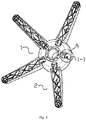
- center piece; 1-1 center piece connecting portion; 1-1.1, outer opening; 1-1.2, lower opening; 1-1.3, rotation limit slot; 1-1.31, support foot connecting portion inlet; 1-1.32, entry channel; 1-1.33, rotation area; 1-1.4, clamping platform; 1-1.5, second hook; 1-2, center hole; 2, support foot/feet; 2, support foot connecting portion; 2-1.1, upper surface; 2-1.2, lower surface; 2-1.21, abutting portion; 2-1.3, side surface; 2-1.4, front surface; 2-1.5, rotation limit protrusion; 2-1.6, first hook; 2-1.61, hook portion; 2-1.62, elastic arm.
- the terms “provided”, “installed”, “connected”, “connecting”, “fixed” and other terms should be understood in a broad sense.
- it can be a fixed connection or a detachable connection; it can be a mechanical connection; it can be directly connected or indirectly connected through an intermediate medium.
- the specific meanings of the above terms in the present disclosure can be understood according to specific circumstances.
- first, second, etc. are only used for descriptive purposes, and cannot be understood as indicating or implying relative importance or implicitly indicating the number of indicated technical features.
- features defined with “first” and “second” may explicitly or implicitly include one or more of these features.
- the connecting structure for connecting the support feet and the center piece may be formed by connecting the center piece connecting portions 1-1 and the support foot connecting portions 2-1.
- each of the center piece connecting portion 1-1 may be a groove provided on the outer periphery of the center piece 1, and the groove may include an outer opening 1-1.1 facing the outer periphery of the center piece 1 and a lower opening 1-1.2 facing the lower side of the center piece 1.
- the two side walls shared by the outer opening 1-1.1 and the lower opening 1-1.2 may be respectively provided with rotation limit slots 1-1.3 of the same shape, and one side of the bottom surface of each of the rotation limit slot 1-1.3 facing the lower opening 1-1.2 may be provided with a support foot connecting portion inlet 1-1.31, above which a through entry channel 1-1.32 is provided, and above the entry channel 1-1.32, a rotation area 1-1.33 is provided.
- the support foot connecting portion 2-1 may be a convex block, including an upper surface 2-1.1, a lower surface 2-1.2, two side surfaces 2-1.3, a front surface 2-1.4, and an upper surface 2-1.1.
- the upper surface 2-1.1 may be adjacent to the opposite surface of the lower opening 1-1.2; the lower surface 2-1.2 is located at the lower opening 1-1.2; the two side surfaces 2-1.3 may be, respectively, adjacent to the two side walls shared by the outer opening 1-1.1 and the lower opening 1-1.2; the front surface 2-1.4 is adjacent to the opposite surface of the outer opening 1-1.1.
- the two side surfaces are respectively provided with cylindrical rotation limit protrusions 2-1.5 with the same shape and protruding outwards, configured to be connected with the rotation limit slot 1-1.3.
- each of the rotation limit protrusion 2-1.5 may enter the entry channel 1-1.32 through the support foot connection inlet 1-1.31, and each of the support feet 2 may be moved upwards until the rotation limit protrusion 2-1.5 reaches the rotation area 1-1.33, and then the rotation limit protrusion 2-1.5 may rotate in the rotation area 1-1.33 to complete the installation.
- a clamping platform 1-1.4 may be also provided on the inner side wall of the central piece connecting portion 1-1 opposite to the outer opening 1-1.1, and the clamping platform 1-1.4 may be provided with a clamping surface facing the upper side of the central piece connecting portion 1-1.
- an abutting portion 2-1.21 may be provided on the lower surface 2-1.2 of the support foot connecting portion 2-1, for abutting and engaging with the clamping surface.
- the abutting portion 2-1.21 may be abutted against the clamping surface. In this way, support may be provided for the downward pressure through the abutment structure of the clamping platform 1-1.4/abutting portion 2-1.21.
- the outer circumferential width of the rotation limit protrusion 2-1.5 may be the same as or slightly smaller than the inner width of the rotation limit slot 1-1.3, such that the rotation limit protrusion 2-1.5 can enter the rotation limit slot 1-1.3, and the rotation limit protrusion 2-1.5 can be restricted by the rotation limit slot 1-1.3 in a horizontal direction, to prevent the chair feet 2 from coming out.
- the rotation area 1-1.33 may include an inner wall with a partial arc-shape, such that the rotation limit protrusion 2-1.5 can rotate within it without hindrance, and may be fully restricted by the arc-shaped inner side wall.
- the upper surface 2-1.1 of the support foot connecting portion 2-1 may be provided with a first hook 2-1.6.
- the opposite surface of the lower opening 1-1.2 in the center piece connecting portion 1-1 may be provided with a second hook 1-1.5.
- the first hook 2-1.6 and the second hook 1-1.5 may be hooked to each other. In this way, the support feet 2 can be difficult to fall down when the corresponding seat is lifted up, so that the seat can be in a suspended state without worrying about the support feet 2 falling, which facilitates the overall short-distance movement of the seat.
- the first hook 2-1.6 may be provided in a through hole or a blind hole provided on the upper surface 2-1.1, and the first hook 2-1.6 may be integrally formed by a hook portion 2-1.61 and an elastic arm 2-1.62, and connected to the upper surface 2-1.1 through the elastic arm 2-1.62. in this way, when the first hook 2-1.6 passes through the second hook 1-1.5, the elastic arm 2-1.62 may be elastically deformed first, so that the first hook 2-1.6 and the second hook 1-1.5 is in contact, and then the elastic deformation is restored to make the first hook 2-1.6 and the second hook 1-1.5 snap into contact.
- the contour of the front surface 2-1.4 may be adapted to the contour of the opposite surface of the outer opening 1-1.1.
- the front surface 2-1.4 may be connected to the opposite surface of the outer opening 1-1.1 in a fitted manner. In this way, when the chassis is under downward pressure, the snapped connection structure can allow the front surface 2-1.4 also participate in the pressure-bearing structure, such that the abutting portion 2-1.21 can be prevented from deforming or even breaking due to excessive force, which further increases the strength and stability of the chassis.
- the two rotation limit protrusions 2-1.5 on the support foot connecting portion 2-1 are inserted into the two rotation limit slots 1-1.3 in the center piece connecting portion 1-1, and each of the rotation limit protrusions 2-1.5 enters the rotation area 1-1.33 through the support foot connection inlet 1-1.31 and the entry channel 1-1.32 in order, and move the rotation limit protrusion 2-1.5 of the support foot 2 to rotate counterclockwise in the rotation area 1-1.33, such that the support foot 2 rotates to the position where the installation is completed.
- the abutting portion 2-1.21 may be snapped with the clamping surface.
- the first hook 2-1.6 and the second hook 1-1.5 when the support foot 2 is rotated to the installed position, the first hook 2-1.6 and the second hook 1-1.5 may be hooked with each other.
- the contour of the front surface 2-1.4 matches the contour of the opposite surface of the outer opening 1-1.1
- the front surface 2-1.4 and the opposite surface of the outer opening 1-1.1 may be connected in a fitted manner.
- one end of the support foot 2 may be provided with the support foot connecting portion 2-1 described in the technical solution of any of the above embodiments.
- the outer periphery of the central piece 1 may be evenly provided with a plurality of the central piece connecting portion 1-1 described in the technical solution of any of the above embodiments.
- the other end of the support foot 2 may be provided with a roller, and the middle of the center piece 1 may be provided with a central hole 1-2 for inserting the seat air rod.
- the contour of the surface where the support foot connecting portion 2-1 is located matches the outer contour of the corresponding part of the center piece 1. In this manner, the seat foot 2 can be prevented from swinging relative to the center piece 1 when the chassis rotates or moves.
- the corresponding chassis may be formed by splicing and installing the support feet 2 and the center piece 1 described in the technical solution of any of the above embodiments.
- the corresponding seat adopts the chassis described in the technical solution of any of the above embodiments.
Landscapes
- Engineering & Computer Science (AREA)
- General Engineering & Computer Science (AREA)
- Mechanical Engineering (AREA)
- Snaps, Bayonet Connections, Set Pins, And Snap Rings (AREA)
- Chair Legs, Seat Parts, And Backrests (AREA)
- Connection Of Plates (AREA)
Applications Claiming Priority (2)
| Application Number | Priority Date | Filing Date | Title |
|---|---|---|---|
| CN201910666597.6A CN110604413B (zh) | 2019-07-23 | 2019-07-23 | 一种可拆装椅脚 |
| PCT/CN2020/101834 WO2021012988A1 (zh) | 2019-07-23 | 2020-07-14 | 支脚与中心件的连接结构、支脚、中心件、底盘及座椅 |
Publications (3)
| Publication Number | Publication Date |
|---|---|
| EP3827704A1 true EP3827704A1 (de) | 2021-06-02 |
| EP3827704A4 EP3827704A4 (de) | 2022-03-09 |
| EP3827704B1 EP3827704B1 (de) | 2023-05-03 |
Family
ID=68890220
Family Applications (1)
| Application Number | Title | Priority Date | Filing Date |
|---|---|---|---|
| EP20844070.1A Active EP3827704B1 (de) | 2019-07-23 | 2020-07-14 | Verbindungsstruktur zwischen füssen und mittelteil |
Country Status (4)
| Country | Link |
|---|---|
| US (1) | US11825958B2 (de) |
| EP (1) | EP3827704B1 (de) |
| CN (1) | CN110604413B (de) |
| WO (1) | WO2021012988A1 (de) |
Families Citing this family (8)
| Publication number | Priority date | Publication date | Assignee | Title |
|---|---|---|---|---|
| CN110604413B (zh) * | 2019-07-23 | 2024-09-06 | 浙江誉越家具有限公司 | 一种可拆装椅脚 |
| CN112932140A (zh) * | 2021-04-30 | 2021-06-11 | 浙江瑞梵家具有限公司 | 一种可拆分的椅脚及装有该椅脚的椅子 |
| CN113116071A (zh) * | 2021-05-14 | 2021-07-16 | 永艺家具股份有限公司 | 一种可拆装椅脚 |
| CN113349585B (zh) * | 2021-07-22 | 2023-07-07 | 安吉史博家具股份有限公司 | 可拆椅脚及其组装方法 |
| US11950706B2 (en) * | 2021-11-08 | 2024-04-09 | Living Style (B.V.I.) Limited | Ready to assemble chair base |
| CN114458670A (zh) * | 2021-12-24 | 2022-05-10 | 安吉海龙家具有限公司 | 一种五星脚底座与支腿的连接结构 |
| CN114343367A (zh) * | 2022-01-12 | 2022-04-15 | 浙江逸辉智能家具有限公司 | 一种椅脚的包装使用方法 |
| CN115539473A (zh) * | 2022-09-30 | 2022-12-30 | 中核华辰工程管理有限公司 | 一种拼接装配式梁柱结构及其施工方法 |
Family Cites Families (34)
| Publication number | Priority date | Publication date | Assignee | Title |
|---|---|---|---|---|
| MY134257A (en) * | 2002-11-22 | 2007-11-30 | Line Entpr Sdn Bhd Off | A rotatable chair base with detachable legs apparatus |
| JP2004180809A (ja) | 2002-12-02 | 2004-07-02 | Taisei Kogyo Kk | 椅子及び足裏指圧具 |
| DK176101B1 (da) * | 2004-11-12 | 2006-06-12 | Inter Ikea Sys Bv | Stol |
| GB2441966B (en) * | 2006-09-20 | 2011-06-15 | Nelson Cho | Detachable supporting framework |
| US9149678B2 (en) | 2007-05-08 | 2015-10-06 | Chair Trainer Ltd. | Exercise apparatus for retrofitting to swivel chairs on castors |
| CN201509927U (zh) | 2009-07-15 | 2010-06-23 | 浙江科达工贸有限公司 | 可拆卸的转椅五星支脚 |
| US10441120B1 (en) * | 2010-04-30 | 2019-10-15 | Unger Marketing International, Llc | Universal connecting members |
| CN201782355U (zh) * | 2010-08-03 | 2011-04-06 | 东莞市清溪旺润塑胶五金制品有限公司 | 组合椅脚 |
| US20120080572A1 (en) * | 2010-10-05 | 2012-04-05 | Chung Ming Lin | Chair Base |
| US20130062495A1 (en) | 2011-09-13 | 2013-03-14 | Peter Lin | Office Chair Foot Base |
| CN202681203U (zh) * | 2012-04-23 | 2013-01-23 | 浙江恒林椅业股份有限公司 | 一种可拆装的五星椅脚结构 |
| CN202858441U (zh) * | 2012-08-22 | 2013-04-10 | 浙江恒林椅业股份有限公司 | 一种椅脚 |
| US20140251400A1 (en) * | 2013-03-06 | 2014-09-11 | Ki Ho Jin | Connector Device for a Telescoping Tent Pole |
| US9155392B2 (en) | 2013-05-28 | 2015-10-13 | Royal Technologies Corporation | Castor apparatus for a chair base and a chair base with a castor apparatus |
| JP3188630U (ja) * | 2013-11-18 | 2014-01-30 | 創譯科技材料有限公司 | 椅子脚部の支持構造 |
| US9144315B1 (en) | 2014-08-22 | 2015-09-29 | Jui-Pin CHENG | Adjustment device of a chair with a foot ring |
| CN204378535U (zh) * | 2015-01-23 | 2015-06-10 | 刘杰 | 一种可拆装椅脚 |
| CN105124963B (zh) * | 2015-09-07 | 2018-01-30 | 中威控股集团有限公司 | 可收纳五星脚 |
| CN205053402U (zh) * | 2015-09-17 | 2016-03-02 | 黄依群 | 一种可拆分的转椅脚 |
| CN206257430U (zh) * | 2016-12-09 | 2017-06-16 | 安吉金泰紧固件有限公司 | 一种五星脚 |
| CN206499205U (zh) * | 2016-12-12 | 2017-09-19 | 覃叁光 | 座椅脚架 |
| CN207653878U (zh) * | 2017-06-08 | 2018-07-27 | 安吉金泰紧固件有限公司 | 一种用于五星脚底座与支脚组装的连接结构 |
| CN107007059B (zh) * | 2017-06-08 | 2023-04-28 | 安吉金泰紧固件有限公司 | 一种用于五星脚底座与支脚组装的连接结构 |
| CN107374128A (zh) * | 2017-08-18 | 2017-11-24 | 安吉飞龙金属制品厂 | 一种可拆分的转椅脚 |
| CN209018147U (zh) * | 2018-01-31 | 2019-06-25 | 湖州奥圣家具有限公司 | 一种转椅的新型椅脚结构 |
| CN208359967U (zh) * | 2018-07-02 | 2019-01-11 | 重庆延锋安道拓汽车部件系统有限公司 | 方便拆卸的汽车座椅调节手柄 |
| US11519446B2 (en) * | 2018-11-05 | 2022-12-06 | Illinois Tool Works Inc. | Fastener feedback feature |
| CN109846241A (zh) * | 2019-03-11 | 2019-06-07 | 李晨欢 | 一种可拆卸五星脚 |
| CN210471571U (zh) * | 2019-07-23 | 2020-05-08 | 浙江誉越家具有限公司 | 一种可拆装椅脚 |
| CN110604413B (zh) * | 2019-07-23 | 2024-09-06 | 浙江誉越家具有限公司 | 一种可拆装椅脚 |
| TWM607172U (zh) | 2020-09-23 | 2021-02-01 | 陳永華 | 辦公椅之組合式椅腳 |
| US20220218110A1 (en) * | 2021-01-11 | 2022-07-14 | Verona Sky International Trading Co., Limited | Three-leg star shaped assembly structure for supporting chair legs |
| US11470970B1 (en) * | 2021-08-13 | 2022-10-18 | Anji Kadi Furniture Technology Co., Ltd. | Connecting mechanism of detachable chair foot and assembling method associated therewith, and chair foot assembly |
| US11950706B2 (en) * | 2021-11-08 | 2024-04-09 | Living Style (B.V.I.) Limited | Ready to assemble chair base |
-
2019
- 2019-07-23 CN CN201910666597.6A patent/CN110604413B/zh active Active
-
2020
- 2020-07-14 WO PCT/CN2020/101834 patent/WO2021012988A1/zh not_active Ceased
- 2020-07-14 US US17/273,002 patent/US11825958B2/en active Active
- 2020-07-14 EP EP20844070.1A patent/EP3827704B1/de active Active
Also Published As
| Publication number | Publication date |
|---|---|
| WO2021012988A1 (zh) | 2021-01-28 |
| EP3827704B1 (de) | 2023-05-03 |
| US20210321777A1 (en) | 2021-10-21 |
| CN110604413B (zh) | 2024-09-06 |
| US11825958B2 (en) | 2023-11-28 |
| EP3827704A4 (de) | 2022-03-09 |
| CN110604413A (zh) | 2019-12-24 |
Similar Documents
| Publication | Publication Date | Title |
|---|---|---|
| US11825958B2 (en) | Connecting structure between feet and central member, feet, central member, chassis and chair | |
| CN208456969U (zh) | 压旋式锁体 | |
| CN201487086U (zh) | 单向组合轴承保持器 | |
| CN210737985U (zh) | 一种卡扣式墙板安装结构 | |
| WO2023169222A1 (zh) | 挂载结构、箱体、电池包及用电装置 | |
| CN106626977A (zh) | 脚轮组件 | |
| CN213452761U (zh) | 一种球形摄像头 | |
| CN213188826U (zh) | 支脚与中心件的连接结构、支脚、中心件、底盘及座椅 | |
| US20080314089A1 (en) | Aluminum alloy connecting and supporting device for glass construction project | |
| CN210799726U (zh) | 一种组合式平面推力滚针轴承 | |
| US20250003541A1 (en) | Connecting member, connecting pipe structure and detachable frame | |
| KR20090091390A (ko) | 알미늄폼의 결속공 보강구조 | |
| CN210265392U (zh) | 一种板式家具用隐形弹连扣连接件 | |
| CN211720512U (zh) | 一种光伏平单轴跟踪系统的传动结构 | |
| CN211793757U (zh) | 一种多浮管支架 | |
| JP2012012079A (ja) | ポンプ | |
| KR102600161B1 (ko) | 철근 연결용 커넥터 | |
| CN224120792U (zh) | 一种连体h型管 | |
| CN206159133U (zh) | 风扇罩及风扇 | |
| CN223908623U (zh) | 便于拆装的轴承 | |
| CN223423452U (zh) | 一种便于拆卸的组合式墙体 | |
| CN212643354U (zh) | 一种可便携组装的连轴器 | |
| CN221374181U (zh) | 管连接接头 | |
| CN216812576U (zh) | 一种膜片联轴器 | |
| CN223257214U (zh) | 一种插接结构件 |
Legal Events
| Date | Code | Title | Description |
|---|---|---|---|
| STAA | Information on the status of an ep patent application or granted ep patent |
Free format text: STATUS: THE INTERNATIONAL PUBLICATION HAS BEEN MADE |
|
| PUAI | Public reference made under article 153(3) epc to a published international application that has entered the european phase |
Free format text: ORIGINAL CODE: 0009012 |
|
| STAA | Information on the status of an ep patent application or granted ep patent |
Free format text: STATUS: REQUEST FOR EXAMINATION WAS MADE |
|
| 17P | Request for examination filed |
Effective date: 20210223 |
|
| AK | Designated contracting states |
Kind code of ref document: A1 Designated state(s): AL AT BE BG CH CY CZ DE DK EE ES FI FR GB GR HR HU IE IS IT LI LT LU LV MC MK MT NL NO PL PT RO RS SE SI SK SM TR |
|
| A4 | Supplementary search report drawn up and despatched |
Effective date: 20220203 |
|
| RIC1 | Information provided on ipc code assigned before grant |
Ipc: F16C 11/10 20060101ALI20220128BHEP Ipc: F16C 11/04 20060101ALI20220128BHEP Ipc: A47C 7/00 20060101AFI20220128BHEP |
|
| DAV | Request for validation of the european patent (deleted) | ||
| DAX | Request for extension of the european patent (deleted) | ||
| GRAP | Despatch of communication of intention to grant a patent |
Free format text: ORIGINAL CODE: EPIDOSNIGR1 |
|
| STAA | Information on the status of an ep patent application or granted ep patent |
Free format text: STATUS: GRANT OF PATENT IS INTENDED |
|
| INTG | Intention to grant announced |
Effective date: 20221115 |
|
| GRAS | Grant fee paid |
Free format text: ORIGINAL CODE: EPIDOSNIGR3 |
|
| GRAA | (expected) grant |
Free format text: ORIGINAL CODE: 0009210 |
|
| STAA | Information on the status of an ep patent application or granted ep patent |
Free format text: STATUS: THE PATENT HAS BEEN GRANTED |
|
| AK | Designated contracting states |
Kind code of ref document: B1 Designated state(s): AL AT BE BG CH CY CZ DE DK EE ES FI FR GB GR HR HU IE IS IT LI LT LU LV MC MK MT NL NO PL PT RO RS SE SI SK SM TR |
|
| REG | Reference to a national code |
Ref country code: GB Ref legal event code: FG4D |
|
| REG | Reference to a national code |
Ref country code: DE Ref legal event code: R096 Ref document number: 602020010527 Country of ref document: DE |
|
| REG | Reference to a national code |
Ref country code: AT Ref legal event code: REF Ref document number: 1563872 Country of ref document: AT Kind code of ref document: T Effective date: 20230515 Ref country code: CH Ref legal event code: EP |
|
| REG | Reference to a national code |
Ref country code: IE Ref legal event code: FG4D |
|
| REG | Reference to a national code |
Ref country code: LT Ref legal event code: MG9D |
|
| REG | Reference to a national code |
Ref country code: NL Ref legal event code: MP Effective date: 20230503 |
|
| REG | Reference to a national code |
Ref country code: AT Ref legal event code: MK05 Ref document number: 1563872 Country of ref document: AT Kind code of ref document: T Effective date: 20230503 |
|
| PG25 | Lapsed in a contracting state [announced via postgrant information from national office to epo] |
Ref country code: SE Free format text: LAPSE BECAUSE OF FAILURE TO SUBMIT A TRANSLATION OF THE DESCRIPTION OR TO PAY THE FEE WITHIN THE PRESCRIBED TIME-LIMIT Effective date: 20230503 Ref country code: PT Free format text: LAPSE BECAUSE OF FAILURE TO SUBMIT A TRANSLATION OF THE DESCRIPTION OR TO PAY THE FEE WITHIN THE PRESCRIBED TIME-LIMIT Effective date: 20230904 Ref country code: NO Free format text: LAPSE BECAUSE OF FAILURE TO SUBMIT A TRANSLATION OF THE DESCRIPTION OR TO PAY THE FEE WITHIN THE PRESCRIBED TIME-LIMIT Effective date: 20230803 Ref country code: NL Free format text: LAPSE BECAUSE OF FAILURE TO SUBMIT A TRANSLATION OF THE DESCRIPTION OR TO PAY THE FEE WITHIN THE PRESCRIBED TIME-LIMIT Effective date: 20230503 Ref country code: ES Free format text: LAPSE BECAUSE OF FAILURE TO SUBMIT A TRANSLATION OF THE DESCRIPTION OR TO PAY THE FEE WITHIN THE PRESCRIBED TIME-LIMIT Effective date: 20230503 Ref country code: AT Free format text: LAPSE BECAUSE OF FAILURE TO SUBMIT A TRANSLATION OF THE DESCRIPTION OR TO PAY THE FEE WITHIN THE PRESCRIBED TIME-LIMIT Effective date: 20230503 |
|
| PG25 | Lapsed in a contracting state [announced via postgrant information from national office to epo] |
Ref country code: RS Free format text: LAPSE BECAUSE OF FAILURE TO SUBMIT A TRANSLATION OF THE DESCRIPTION OR TO PAY THE FEE WITHIN THE PRESCRIBED TIME-LIMIT Effective date: 20230503 Ref country code: PL Free format text: LAPSE BECAUSE OF FAILURE TO SUBMIT A TRANSLATION OF THE DESCRIPTION OR TO PAY THE FEE WITHIN THE PRESCRIBED TIME-LIMIT Effective date: 20230503 Ref country code: LV Free format text: LAPSE BECAUSE OF FAILURE TO SUBMIT A TRANSLATION OF THE DESCRIPTION OR TO PAY THE FEE WITHIN THE PRESCRIBED TIME-LIMIT Effective date: 20230503 Ref country code: LT Free format text: LAPSE BECAUSE OF FAILURE TO SUBMIT A TRANSLATION OF THE DESCRIPTION OR TO PAY THE FEE WITHIN THE PRESCRIBED TIME-LIMIT Effective date: 20230503 Ref country code: IS Free format text: LAPSE BECAUSE OF FAILURE TO SUBMIT A TRANSLATION OF THE DESCRIPTION OR TO PAY THE FEE WITHIN THE PRESCRIBED TIME-LIMIT Effective date: 20230903 Ref country code: HR Free format text: LAPSE BECAUSE OF FAILURE TO SUBMIT A TRANSLATION OF THE DESCRIPTION OR TO PAY THE FEE WITHIN THE PRESCRIBED TIME-LIMIT Effective date: 20230503 Ref country code: GR Free format text: LAPSE BECAUSE OF FAILURE TO SUBMIT A TRANSLATION OF THE DESCRIPTION OR TO PAY THE FEE WITHIN THE PRESCRIBED TIME-LIMIT Effective date: 20230804 |
|
| PG25 | Lapsed in a contracting state [announced via postgrant information from national office to epo] |
Ref country code: FI Free format text: LAPSE BECAUSE OF FAILURE TO SUBMIT A TRANSLATION OF THE DESCRIPTION OR TO PAY THE FEE WITHIN THE PRESCRIBED TIME-LIMIT Effective date: 20230503 |
|
| PG25 | Lapsed in a contracting state [announced via postgrant information from national office to epo] |
Ref country code: SK Free format text: LAPSE BECAUSE OF FAILURE TO SUBMIT A TRANSLATION OF THE DESCRIPTION OR TO PAY THE FEE WITHIN THE PRESCRIBED TIME-LIMIT Effective date: 20230503 |
|
| PG25 | Lapsed in a contracting state [announced via postgrant information from national office to epo] |
Ref country code: SM Free format text: LAPSE BECAUSE OF FAILURE TO SUBMIT A TRANSLATION OF THE DESCRIPTION OR TO PAY THE FEE WITHIN THE PRESCRIBED TIME-LIMIT Effective date: 20230503 Ref country code: SK Free format text: LAPSE BECAUSE OF FAILURE TO SUBMIT A TRANSLATION OF THE DESCRIPTION OR TO PAY THE FEE WITHIN THE PRESCRIBED TIME-LIMIT Effective date: 20230503 Ref country code: RO Free format text: LAPSE BECAUSE OF FAILURE TO SUBMIT A TRANSLATION OF THE DESCRIPTION OR TO PAY THE FEE WITHIN THE PRESCRIBED TIME-LIMIT Effective date: 20230503 Ref country code: EE Free format text: LAPSE BECAUSE OF FAILURE TO SUBMIT A TRANSLATION OF THE DESCRIPTION OR TO PAY THE FEE WITHIN THE PRESCRIBED TIME-LIMIT Effective date: 20230503 Ref country code: DK Free format text: LAPSE BECAUSE OF FAILURE TO SUBMIT A TRANSLATION OF THE DESCRIPTION OR TO PAY THE FEE WITHIN THE PRESCRIBED TIME-LIMIT Effective date: 20230503 Ref country code: CZ Free format text: LAPSE BECAUSE OF FAILURE TO SUBMIT A TRANSLATION OF THE DESCRIPTION OR TO PAY THE FEE WITHIN THE PRESCRIBED TIME-LIMIT Effective date: 20230503 |
|
| REG | Reference to a national code |
Ref country code: DE Ref legal event code: R097 Ref document number: 602020010527 Country of ref document: DE |
|
| PG25 | Lapsed in a contracting state [announced via postgrant information from national office to epo] |
Ref country code: MC Free format text: LAPSE BECAUSE OF FAILURE TO SUBMIT A TRANSLATION OF THE DESCRIPTION OR TO PAY THE FEE WITHIN THE PRESCRIBED TIME-LIMIT Effective date: 20230503 |
|
| PG25 | Lapsed in a contracting state [announced via postgrant information from national office to epo] |
Ref country code: MC Free format text: LAPSE BECAUSE OF FAILURE TO SUBMIT A TRANSLATION OF THE DESCRIPTION OR TO PAY THE FEE WITHIN THE PRESCRIBED TIME-LIMIT Effective date: 20230503 |
|
| REG | Reference to a national code |
Ref country code: CH Ref legal event code: PL |
|
| PLBE | No opposition filed within time limit |
Free format text: ORIGINAL CODE: 0009261 |
|
| STAA | Information on the status of an ep patent application or granted ep patent |
Free format text: STATUS: NO OPPOSITION FILED WITHIN TIME LIMIT |
|
| REG | Reference to a national code |
Ref country code: BE Ref legal event code: MM Effective date: 20230731 |
|
| PG25 | Lapsed in a contracting state [announced via postgrant information from national office to epo] |
Ref country code: LU Free format text: LAPSE BECAUSE OF NON-PAYMENT OF DUE FEES Effective date: 20230714 |
|
| PG25 | Lapsed in a contracting state [announced via postgrant information from national office to epo] |
Ref country code: LU Free format text: LAPSE BECAUSE OF NON-PAYMENT OF DUE FEES Effective date: 20230714 |
|
| 26N | No opposition filed |
Effective date: 20240206 |
|
| REG | Reference to a national code |
Ref country code: IE Ref legal event code: MM4A |
|
| PG25 | Lapsed in a contracting state [announced via postgrant information from national office to epo] |
Ref country code: CH Free format text: LAPSE BECAUSE OF NON-PAYMENT OF DUE FEES Effective date: 20230731 |
|
| PG25 | Lapsed in a contracting state [announced via postgrant information from national office to epo] |
Ref country code: SI Free format text: LAPSE BECAUSE OF FAILURE TO SUBMIT A TRANSLATION OF THE DESCRIPTION OR TO PAY THE FEE WITHIN THE PRESCRIBED TIME-LIMIT Effective date: 20230503 |
|
| PG25 | Lapsed in a contracting state [announced via postgrant information from national office to epo] |
Ref country code: SI Free format text: LAPSE BECAUSE OF FAILURE TO SUBMIT A TRANSLATION OF THE DESCRIPTION OR TO PAY THE FEE WITHIN THE PRESCRIBED TIME-LIMIT Effective date: 20230503 Ref country code: IT Free format text: LAPSE BECAUSE OF FAILURE TO SUBMIT A TRANSLATION OF THE DESCRIPTION OR TO PAY THE FEE WITHIN THE PRESCRIBED TIME-LIMIT Effective date: 20230503 Ref country code: BE Free format text: LAPSE BECAUSE OF NON-PAYMENT OF DUE FEES Effective date: 20230731 |
|
| PG25 | Lapsed in a contracting state [announced via postgrant information from national office to epo] |
Ref country code: IE Free format text: LAPSE BECAUSE OF NON-PAYMENT OF DUE FEES Effective date: 20230714 |
|
| PG25 | Lapsed in a contracting state [announced via postgrant information from national office to epo] |
Ref country code: IE Free format text: LAPSE BECAUSE OF NON-PAYMENT OF DUE FEES Effective date: 20230714 |
|
| PGFP | Annual fee paid to national office [announced via postgrant information from national office to epo] |
Ref country code: DE Payment date: 20240806 Year of fee payment: 5 |
|
| PGFP | Annual fee paid to national office [announced via postgrant information from national office to epo] |
Ref country code: GB Payment date: 20240730 Year of fee payment: 5 |
|
| PGFP | Annual fee paid to national office [announced via postgrant information from national office to epo] |
Ref country code: FR Payment date: 20240731 Year of fee payment: 5 |
|
| PG25 | Lapsed in a contracting state [announced via postgrant information from national office to epo] |
Ref country code: BG Free format text: LAPSE BECAUSE OF FAILURE TO SUBMIT A TRANSLATION OF THE DESCRIPTION OR TO PAY THE FEE WITHIN THE PRESCRIBED TIME-LIMIT Effective date: 20230503 |
|
| PG25 | Lapsed in a contracting state [announced via postgrant information from national office to epo] |
Ref country code: BG Free format text: LAPSE BECAUSE OF FAILURE TO SUBMIT A TRANSLATION OF THE DESCRIPTION OR TO PAY THE FEE WITHIN THE PRESCRIBED TIME-LIMIT Effective date: 20230503 |
|
| PG25 | Lapsed in a contracting state [announced via postgrant information from national office to epo] |
Ref country code: CY Free format text: LAPSE BECAUSE OF FAILURE TO SUBMIT A TRANSLATION OF THE DESCRIPTION OR TO PAY THE FEE WITHIN THE PRESCRIBED TIME-LIMIT; INVALID AB INITIO Effective date: 20200714 |
|
| PG25 | Lapsed in a contracting state [announced via postgrant information from national office to epo] |
Ref country code: HU Free format text: LAPSE BECAUSE OF FAILURE TO SUBMIT A TRANSLATION OF THE DESCRIPTION OR TO PAY THE FEE WITHIN THE PRESCRIBED TIME-LIMIT; INVALID AB INITIO Effective date: 20200714 |
|
| PG25 | Lapsed in a contracting state [announced via postgrant information from national office to epo] |
Ref country code: TR Free format text: LAPSE BECAUSE OF FAILURE TO SUBMIT A TRANSLATION OF THE DESCRIPTION OR TO PAY THE FEE WITHIN THE PRESCRIBED TIME-LIMIT Effective date: 20230503 |
|
| REG | Reference to a national code |
Ref country code: DE Ref legal event code: R119 Ref document number: 602020010527 Country of ref document: DE |
|
| GBPC | Gb: european patent ceased through non-payment of renewal fee |
Effective date: 20250714 |
|
| PG25 | Lapsed in a contracting state [announced via postgrant information from national office to epo] |
Ref country code: GB Free format text: LAPSE BECAUSE OF NON-PAYMENT OF DUE FEES Effective date: 20250714 |
|
| PG25 | Lapsed in a contracting state [announced via postgrant information from national office to epo] |
Ref country code: DE Free format text: LAPSE BECAUSE OF NON-PAYMENT OF DUE FEES Effective date: 20260203 |
|
| PG25 | Lapsed in a contracting state [announced via postgrant information from national office to epo] |
Ref country code: FR Free format text: LAPSE BECAUSE OF NON-PAYMENT OF DUE FEES Effective date: 20250731 |