EP3827736B1 - Dispositif de tomographie par cohérence optique - Google Patents
Dispositif de tomographie par cohérence optique Download PDFInfo
- Publication number
- EP3827736B1 EP3827736B1 EP18927293.3A EP18927293A EP3827736B1 EP 3827736 B1 EP3827736 B1 EP 3827736B1 EP 18927293 A EP18927293 A EP 18927293A EP 3827736 B1 EP3827736 B1 EP 3827736B1
- Authority
- EP
- European Patent Office
- Prior art keywords
- base
- drive mechanism
- connecting part
- hollow shaft
- movable base
- Prior art date
- Legal status (The legal status is an assumption and is not a legal conclusion. Google has not performed a legal analysis and makes no representation as to the accuracy of the status listed.)
- Active
Links
Images
Classifications
-
- G—PHYSICS
- G01—MEASURING; TESTING
- G01B—MEASURING LENGTH, THICKNESS OR SIMILAR LINEAR DIMENSIONS; MEASURING ANGLES; MEASURING AREAS; MEASURING IRREGULARITIES OF SURFACES OR CONTOURS
- G01B9/00—Measuring instruments characterised by the use of optical techniques
- G01B9/02—Interferometers
- G01B9/0209—Low-coherence interferometers
- G01B9/02091—Tomographic interferometers, e.g. based on optical coherence
-
- A—HUMAN NECESSITIES
- A61—MEDICAL OR VETERINARY SCIENCE; HYGIENE
- A61B—DIAGNOSIS; SURGERY; IDENTIFICATION
- A61B5/00—Measuring for diagnostic purposes; Identification of persons
- A61B5/0059—Measuring for diagnostic purposes; Identification of persons using light, e.g. diagnosis by transillumination, diascopy, fluorescence
- A61B5/0062—Arrangements for scanning
- A61B5/0066—Optical coherence imaging
-
- A—HUMAN NECESSITIES
- A61—MEDICAL OR VETERINARY SCIENCE; HYGIENE
- A61B—DIAGNOSIS; SURGERY; IDENTIFICATION
- A61B5/00—Measuring for diagnostic purposes; Identification of persons
- A61B5/0059—Measuring for diagnostic purposes; Identification of persons using light, e.g. diagnosis by transillumination, diascopy, fluorescence
- A61B5/0082—Measuring for diagnostic purposes; Identification of persons using light, e.g. diagnosis by transillumination, diascopy, fluorescence adapted for particular medical purposes
- A61B5/0084—Measuring for diagnostic purposes; Identification of persons using light, e.g. diagnosis by transillumination, diascopy, fluorescence adapted for particular medical purposes for introduction into the body, e.g. by catheters
-
- A—HUMAN NECESSITIES
- A61—MEDICAL OR VETERINARY SCIENCE; HYGIENE
- A61B—DIAGNOSIS; SURGERY; IDENTIFICATION
- A61B5/00—Measuring for diagnostic purposes; Identification of persons
- A61B5/68—Arrangements of detecting, measuring or recording means, e.g. sensors, in relation to patient
- A61B5/6846—Arrangements of detecting, measuring or recording means, e.g. sensors, in relation to patient specially adapted to be brought in contact with an internal body part, i.e. invasive
- A61B5/6847—Arrangements of detecting, measuring or recording means, e.g. sensors, in relation to patient specially adapted to be brought in contact with an internal body part, i.e. invasive mounted on an invasive device
- A61B5/6852—Catheters
-
- G—PHYSICS
- G01—MEASURING; TESTING
- G01B—MEASURING LENGTH, THICKNESS OR SIMILAR LINEAR DIMENSIONS; MEASURING ANGLES; MEASURING AREAS; MEASURING IRREGULARITIES OF SURFACES OR CONTOURS
- G01B9/00—Measuring instruments characterised by the use of optical techniques
- G01B9/02—Interferometers
- G01B9/02049—Interferometers characterised by particular mechanical design details
-
- G—PHYSICS
- G01—MEASURING; TESTING
- G01B—MEASURING LENGTH, THICKNESS OR SIMILAR LINEAR DIMENSIONS; MEASURING ANGLES; MEASURING AREAS; MEASURING IRREGULARITIES OF SURFACES OR CONTOURS
- G01B9/00—Measuring instruments characterised by the use of optical techniques
- G01B9/02—Interferometers
- G01B9/02049—Interferometers characterised by particular mechanical design details
- G01B9/0205—Interferometers characterised by particular mechanical design details of probe head
-
- G—PHYSICS
- G02—OPTICS
- G02B—OPTICAL ELEMENTS, SYSTEMS OR APPARATUS
- G02B6/00—Light guides; Structural details of arrangements comprising light guides and other optical elements, e.g. couplings
- G02B6/24—Coupling light guides
- G02B6/36—Mechanical coupling means
- G02B6/3604—Rotary joints allowing relative rotational movement between opposing fibre or fibre bundle ends
-
- A—HUMAN NECESSITIES
- A61—MEDICAL OR VETERINARY SCIENCE; HYGIENE
- A61B—DIAGNOSIS; SURGERY; IDENTIFICATION
- A61B2562/00—Details of sensors; Constructional details of sensor housings or probes; Accessories for sensors
- A61B2562/22—Arrangements of medical sensors with cables or leads; Connectors or couplings specifically adapted for medical sensors
- A61B2562/225—Connectors or couplings
- A61B2562/228—Sensors with optical connectors
-
- A—HUMAN NECESSITIES
- A61—MEDICAL OR VETERINARY SCIENCE; HYGIENE
- A61B—DIAGNOSIS; SURGERY; IDENTIFICATION
- A61B5/00—Measuring for diagnostic purposes; Identification of persons
- A61B5/0059—Measuring for diagnostic purposes; Identification of persons using light, e.g. diagnosis by transillumination, diascopy, fluorescence
- A61B5/0073—Measuring for diagnostic purposes; Identification of persons using light, e.g. diagnosis by transillumination, diascopy, fluorescence by tomography, i.e. reconstruction of 3D images from 2D projections
Definitions
- the present invention relates to an optical coherence tomography device.
- OCT Optical Coherence Tomography
- CT optical Coherence Tomography
- two- or three-dimension images of biological tissues are captured by detecting back-reflection or scattering signals of low-coherence light incident on different tissue types.
- OCT was first proposed by a research team from the Massachusetts Institute of Technology in 1991.
- traditional imaging techniques such as nuclear magnetic resonance, X-rays and ultrasound
- OCT has a higher resolution, reaching up to the micron level, and also there is no risk of radiation since OCT devices typically operate in the near-infrared range.
- OCT is regarded as non-radiative computerized tomography (CT), but has a resolution that is 100 times higher than that of CT.
- OCT Compared with optical confocal microscopy for in-vitro detection, OCT has a greater penetration depth and is thus capable of detecting micron-level morphological changes of biological tissues. Moreover, OCT systems are easy to miniaturize and make portable by virtue of optical fiber technology, and thus are capable of performing real-time detection on tissues of bodies. In recent years, OCT, as a new imaging technique, has advanced by leaps and bounds. Traditional OCT equipment is widely used in clinical diagnosis in the field of ophthalmology. Additionally, researchers are using OCT imaging methods in various applications such as skin, teeth, cardiovascular, esophagus and brain imaging in combination with optical fiber technology and endoscopy.
- the main body of an OCT device transmits the optical signal to a fiber optic rotary joint, which transmits the optical signal.
- an optical imaging catheter is connected to a drive unit of the main body and an optical path of the fiber optic rotary joint.
- the drive unit drives the optical imaging catheter to perform a 360° rotation scan about the main axis thereof to obtain a B-scan image.
- the optical imaging catheter should be disassembled for cleaning and disinfection. It is highly desirable to provide a method to connect and remove the optical catheter from the drive unit conveniently.
- JP2017093537A1 discloses an OCT device that does not cause a problem in a catheter sheath by the rotation of a flexible shaft even if the catheter sheath is bent when an optical fiber is moved in a tip direction while being rotated.
- the fiber optic rotary joint With reference to the positioning of the fiber optic rotary joint, the hollow shaft and the optical imaging catheter it discloses that the optic rotary joint and the optical imaging catheter are not aligned.
- the objective of the present invention is to provide an optical coherence tomography device, which is capable of connecting and removing the optical catheter from the drive unit conveniently either manually or automatically.
- the objective of the present invention is achieved by adopting the following technical solutions.
- An optical coherence tomography device includes:
- a clamping member and a third drive mechanism are arranged on the movable base.
- the clamping member is arranged under the second connecting part.
- the third drive mechanism is configured to drive the clamping member to move toward or away from the second connecting part along the height direction of the base. When the first connecting part and the second connecting part are connected, the clamping member moves toward the second connecting part to tightly clamp the first connecting part and the second connecting part.
- the third drive mechanism includes a first linear motor.
- the housing of the first linear motor is fixedly connected to the movable base.
- the clamping member is fixedly connected to a power output end of the first linear motor.
- the detection end of the base is provided with a first trigger switch.
- the first trigger switch is configured to transmit a first trigger signal to the third drive mechanism after the clamping member tightly clamps the first connecting part and the second connecting part.
- the first drive mechanism includes a synchronous motor, a synchronous belt and two synchronous wheels.
- the housing of the synchronous motor is fixedly connected to the movable base, and a rotating shaft of the synchronous motor is fixedly connected to one of the synchronous wheels.
- the other synchronous wheel is sleeved on the outside of the hollow shaft and fixedly connected to the hollow shaft.
- the two ends of the synchronous belt are synchronously wound around the two synchronous wheels.
- the second drive mechanism includes a leadscrew motor, a leadscrew, a nut, and a guide mechanism.
- the housing of the leadscrew motor is fixedly connected to the base.
- the leadscrew extends along the length direction of the base and is synchronously connected to a rotor of the leadscrew motor.
- the nut is sleeved on the outside of the leadscrew and is in a thread-fit with the leadscrew.
- the nut is fixedly connected to the bottom end of the movable base, and is guided by the guide mechanism to move along the direction in which the leadscrew extends.
- the detection end of the base is provided with a stop block and a fourth drive mechanism.
- the stop block is movably mounted at the detection end.
- the fourth drive mechanism is configured to drive the stop block to move toward or away from the connecting end.
- the stop block is configured to block the end surface of the connecting end after moving toward the connecting end.
- the fourth drive mechanism includes a second linear motor.
- the housing of the second linear motor is fixedly connected to the base.
- the stop block is fixedly connected to a power output end of the second linear motor.
- the detection end of the base is provided with a second trigger switch.
- the second trigger switch is configured to transmit a second trigger signal to the fourth drive mechanism when the stop block blocks the end surface of the connecting end.
- a third trigger switch is arranged on the hollow shaft.
- the third trigger switch is configured to transmit a third trigger signal to the first drive mechanism after the hollow shaft rotates an angle A.
- the movable base moves toward the detection end to connect the second connecting part of the hollow shaft on the movable base to the first connecting part of the optical imaging catheter, so that the optical imaging catheter is synchronously coupled with the hollow shaft.
- the optical imaging catheter is either manually or automatically connected to or disconnected from the optical path of the optical fiber of the fiber optic rotary joint on the movable base very conveniently.
- the hollow shaft is driven to rotate by the first drive mechanism to drive the optical imaging catheter to rotate to capture an image of a single section of a lumen.
- the second drive mechanism drives the movable base to reciprocate to drive the optical imaging catheter to reciprocate, so that the optical imaging catheter is capable of scanning the whole section of the lumen to capture a stereoscopic 3D image.
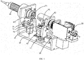
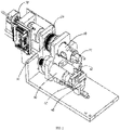
- an optical coherence tomography device includes the base 10, the movable base 20, and a second drive mechanism.
- One end of the base 10 is provided with a detection end, and the other end of the base 10 is provided with a mounting end.
- the optical imaging catheter 40 is pivotally connected to the detection end, and the optical imaging catheter 40 can move along the length direction of the base 10.
- the optical imaging catheter 40 is provided with an imaging end and the connecting end 41.
- the connecting end 41 is detachably connected to the detection end, and the connecting end 41 is provided with the first connecting part 411.
- the movable base 20 is mounted at the mounting end and can move toward or away from the detection end along the length direction of the base 10.
- the movable base 20 is provided with the fiber optic rotary joint 30, the hollow shaft 50 and a first drive mechanism.
- the fiber optic rotary joint 30 is configured to transmit optical signals.
- the fiber optic rotary joint 30 is set away from the detection end and is fixedly connected to the movable base 20, and the end of the fiber optic rotary joint 30 adjacent to the detection end extends into the hollow shaft 50.
- the hollow shaft 50 is pivotally connected to the movable base 20.
- the first drive mechanism is configured to drive the hollow shaft 50 to rotate.
- the end of the hollow shaft 50 adjacent to the detection end is provided with the second connecting part 51.
- the second connecting part 51 is configured to be connected to the first connecting part 411, so that the optical imaging catheter 40 is coupled with the hollow shaft 50 to connect the optical imaging catheter 40 to an optical path of the fiber optic rotary joint 30.
- the movable base 20 is driven by the second drive mechanism to move along the length direction of the base 10.
- the second drive mechanism drives the movable base 20 to move toward the detection end to connect the second connecting part 51 of the hollow shaft 50 on the movable base 20 to the first connecting part 411 of the optical imaging catheter 40, so that the optical imaging catheter 40 is synchronously coupled with the hollow shaft 50, and the optical imaging catheter 40 is automatically or manually connected to or disconnected from the optical path of the optical fiber of the fiber optic rotary joint 30 on the movable base 20.
- the imaging end of the connected optical imaging catheter 40 is applied to the inside of a lumen for detection.
- the main body of the device is turned on to transmit an optical signal to the fiber optic rotary joint 30, and the optical signal is transmitted to the optical imaging catheter 40 through the fiber optic rotary joint 30.
- the hollow shaft 50 is driven to rotate by the first drive mechanism, thereby driving the optical imaging catheter 40 to rotate, so that the optical imaging catheter 40 is capable of capturing an image of a single section of the lumen.
- the second drive mechanism drives the movable base 20 to reciprocate, thereby driving the optical imaging catheter 40 to reciprocate, so that the optical imaging catheter 40 is capable of scanning the whole section of the lumen to capture a stereoscopic 3D image.
- the fiber optic rotary joint 30, the hollow shaft 50 and the optical imaging catheter 40 are coaxially connected on the base 10 in the following manner.
- the movable base 20 is provided with two mounting holes that are coaxially formed, in which the fiber optic rotary joint 30 and the hollow shaft 50 are mounted.
- the detection end of the base 10 is provided with a mounting hole in which the optical imaging catheter 40 is mounted, and the mounting hole is coaxial with the two mounting holes to facilitate automatic connection.
- first connecting part 411 can be implemented by using a known connecting male terminal of an optical fiber connector in the prior art
- second connecting part 51 can be implemented by using a known connecting female terminal of the optical fiber connector in the prior art.
- the clamping member 61 and a third drive mechanism are arranged on the movable base 20.
- the clamping member 61 is arranged under the second connecting part 51.
- the third drive mechanism is configured to drive the clamping member 61 to move toward or away from the second connecting part 51 along the height direction of the base 10, that is, to drive the clamping member 61 to move up and down.
- the clamping member 61 moves toward the second connecting part 51 to tightly clamp the first connecting part 411 and the second connecting part 51.
- the third drive mechanism drives the clamping member 61 to move toward the second connecting part 51, so that the clamping member 61 securely clamps the connection portion between the first connecting part 411 and the second connecting part 51 to reinforce the connection structure thereof.
- the clamping member 61 is driven to move downward by the third drive mechanism.
- the clamping member 61 can be implemented by using a structure such as a clamping jaw in the prior art.
- the third drive mechanism includes the first linear motor 60.
- the housing of the first linear motor 60 is fixedly connected to the movable base 20.
- the clamping member 61 is fixedly connected to the power output end of the first linear motor 60, that is, the first linear motor 60 can drive the clamping member 61 to move up and down.
- the third drive mechanism has a simple driving structure and is convenient to use.
- the third drive mechanism can also be implemented by other linear motion output mechanisms such as a drive cylinder and a leadscrew transmission mechanism in the prior art.
- the detection end of the base 10 is provided with a first trigger switch.
- the first trigger switch is configured to transmit a first trigger signal to the third drive mechanism after the clamping member 61 tightly clamps the first connecting part 411 and the second connecting part 51. That is, after the clamping member 61 tightly clamps the first connecting part 411 and the second connecting part 51, the first trigger switch 62 is triggered to control the third drive mechanism to stop in time.
- the first trigger switch 62 is a grating sensor
- the clamping member 61 is provided with an optical path blocking plate. The clamping member 61 moves up and down, so that the optical path blocking plate can disconnect or connect the optical path of the grating sensor to control the third drive mechanism to start or stop.
- the first trigger switch can also be a contact switch in the prior art.
- the first drive mechanism includes the synchronous motor 80, a synchronous belt and two synchronous wheels 81.
- the housing of the synchronous motor 80 is fixedly connected to the movable base 20, and a rotating shaft of the synchronous motor 80 is fixedly connected to one of the synchronous wheels 81.
- the other synchronous wheel 81 is sleeved on the outside of the hollow shaft 50 and fixedly connected to the hollow shaft 50.
- the two ends of the synchronous belt are synchronously wound around the two synchronous wheels 81.
- the first drive mechanism can also be directly implemented by an electric motor, or implemented by a combination of an electric motor and a gear transmission structure.
- the second drive mechanism specifically includes a leadscrew motor, a leadscrew, a nut, and a guide mechanism.
- the housing of the leadscrew motor is fixedly connected to the base 10.
- the leadscrew extends along the length direction of the base 10 and is synchronously connected to a rotor of the leadscrew motor.
- the nut is sleeved on the outside of the leadscrew and is in a thread-fit with the leadscrew.
- the nut is fixedly connected to the bottom end of the movable base 20, and is guided by the guide mechanism to move along the direction in which the leadscrew extends.
- the leadscrew motor is started to rotate to drive the leadscrew to rotate, and the rotation of the leadscrew is transformed into a linear motion along the direction in which the leadscrew extends (that is, the length direction of the base 10) through the nut that is in a thread-fit with the leadscrew and the guidance of the guide mechanism, so as to drive the movable base 20 fixedly connected to the nut to move along the length direction of the base 10.
- the guide mechanism specifically includes a sliding rail fixedly connected to the base 10 and a sliding groove formed at the bottom end of the movable base 20, and the sliding rail is slidably embedded in the sliding groove.
- the fourth trigger switch 11 can be arranged on the base 10.
- the fourth trigger switch 11 is configured to transmit a signal to the second drive mechanism to control the movable base 20 to start or stop in time when the movable base 20 moves to the two ends of the base 10.
- the fourth trigger switch 11 can also adopt a grating sensor.
- An optical path blocking plate is arranged on the movable base 20. The movable base 20 moves back and forth until the optical path blocking plate is disconnected or connected to the optical path of the grating sensor to control the second drive mechanism to start or stop.
- the fourth trigger switch 11 can also be a contact switch in the prior art.
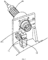
- the detection end of the base 10 is provided with the stop block 71 and a fourth drive mechanism.
- the stop block 71 is movably mounted at the detection end.
- the fourth drive mechanism is configured to drive the stop block 71 to move toward or away from the connecting end 41.
- the stop block 71 is configured to block the end surface of the connecting end 41 after moving toward the connecting end 41.
- the stop block 71 is driven to move upward by the fourth drive mechanism to block the end surface of the connecting end 41 of the optical imaging catheter 40, so that the movable base 20 moves away from the optical imaging catheter 40, and the movement of the optical imaging catheter 40 is stopped by the stop block 71, so that the second connecting part 51 is separate and disconnected from the first connecting part 411.
- the first connecting part 411 is separate from the second connecting part 51 manually.
- the fourth drive mechanism includes the second linear motor 70.
- the housing of the second linear motor 70 is fixedly connected to the base 10.
- the stop block 71 is fixedly connected to the power output end of the second linear motor 70. That is, the stop block 71 is driven by the second linear motor 70 to move up and down.
- the driving structure is simple and convenient to use.
- the fourth drive mechanism can also be implemented by other linear motion output mechanisms such as a drive cylinder and a leadscrew drive mechanism in the prior art.
- the detection end of the base 10 is provided with the second trigger switch 72.
- the second trigger switch 72 is configured to transmit a second trigger signal to the fourth drive mechanism when the stop block 71 blocks the end surface of the connecting end 41. That is, when the stop block 71 moves to the end surface of the connecting end 41, the second trigger switch 72 is triggered to control the fourth drive mechanism to stop in time.
- the second trigger switch 72 can also adopt a grating sensor, and an optical path blocking plate is arranged on the stop block 71. When the stop block 71 moves up and down, the optical path blocking plate can disconnect or connect the optical path of the grating sensor to control the fourth drive mechanism to start or stop.
- the second trigger switch 72 can also be a contact switch in the prior art.
- the third trigger switch 82 is arranged on the hollow shaft 50, and the third trigger switch 82 is configured to transmit a third trigger signal to the first drive mechanism after the hollow shaft 50 rotates an angle A.
- the third trigger switch 82 adopts a grating sensor, and an optical path blocking plate is sleeved on the hollow shaft 50.
- a notch is provided on the optical path blocking plate, and the position of the notch located in the optical path of the grating sensor (that is, the optical path is connected) serves as a zero position.
- the first drive mechanism is controlled to start, that is, the hollow shaft 50 starts to rotate at a position as the starting point for recording the 360° scan performed by the optical imaging catheter 40.
- the notch of the optical path blocking plate returns to the zero position, which is counted as the first 360° scan of the optical imaging catheter 40 at this time.
- the third trigger switch 82 can also be implemented by a contact switch in the prior art.
Landscapes
- Health & Medical Sciences (AREA)
- Life Sciences & Earth Sciences (AREA)
- Physics & Mathematics (AREA)
- General Physics & Mathematics (AREA)
- General Health & Medical Sciences (AREA)
- Engineering & Computer Science (AREA)
- Heart & Thoracic Surgery (AREA)
- Radiology & Medical Imaging (AREA)
- Biophysics (AREA)
- Pathology (AREA)
- Nuclear Medicine, Radiotherapy & Molecular Imaging (AREA)
- Biomedical Technology (AREA)
- Veterinary Medicine (AREA)
- Medical Informatics (AREA)
- Molecular Biology (AREA)
- Surgery (AREA)
- Animal Behavior & Ethology (AREA)
- Public Health (AREA)
- Optics & Photonics (AREA)
- Investigating Or Analysing Materials By Optical Means (AREA)
Claims (10)
- Un dispositif de tomographie par cohérence optique, comprenant :une base (10) dans laquelle une première extrémité de la base est munie d'une extrémité de détection, et une deuxième extrémité de la base est munie d'une extrémité de montage ;un cathéter d'imagerie optique (40) connecté de façon coaxiale à l'extrémité de détection ;le cathéter d'imagerie optique est configuré pour se déplacer dans le sens de la longueur de la base ;le cathéter d'imagerie optique est muni d'une extrémité d'imagerie et d'une extrémité de connexion (41), dans lequel l'extrémité de connexion est connectée de façon détachable à l'extrémité de détection, et l'extrémité de connexion est munie d'une première partie de connexion (411) ;une base mobile (20) montée sur l'extrémité de montage et la base mobile étant configurée pour se déplacer vers ou à distance de l'extrémité de détection dans le sens de la longueur de la base ;la base mobile est munie d'un joint rotatif à fibre optique (30) configuré pour transmettre des signaux optiques, un arbre creux et un premier mécanisme d'entraînement ;le joint rotatif à fibre optique est agencé à distance de l'extrémité de détection, et le joint rotatif à fibre optique est connecté fixement à la base mobile ;une extrémité du joint rotatif à fibre optique est adjacente à l'extrémité de détection, et l'extrémité du joint rotatif à fibre optique se prolonge dans l'arbre creux ;l'arbre creux est connecté de façon coaxiale à la base mobile, et l'extrémité de l'arbre creux adjacente à l'extrémité de détection est munie d'une deuxième partie de connexion (51) ;lorsque la base mobile se déplace vers l'extrémité de détection, la deuxième partie de connexion est configurée pour être connectée à la première partie de connexion, et le cathéter d'imagerie optique est couplé à l'arbre creux pour connecter le cathéter d'imagerie optique à un chemin optique du joint rotatif à fibre optique ;le premier mécanisme d'entraînement est configuré pour entraîner la rotation de l'arbre creux ; etun deuxième mécanisme d'entraînement est configuré pour entraîner le déplacement de la base mobile dans le sens de la longueur de la base ;caractérisé en ce que le joint rotatif à fibre optique, l'arbre creux et le cathéter à imagerie optique sont connectés de façon coaxiale à la base, la base mobile est munie de deux trous de montage formés de façon coaxiale, dans lesquels le joint rotatif à fibre optique et l'arbre creux sont montés, l'extrémité de détection de la base est munie d'un trou de montage dans lequel le cathéter d'imagerie optique est monté, et le trou de montage est coaxial avec les deux trous de montage.
- Un dispositif de tomographie par cohérence optique selon la revendication 1, dans lequelun élément de serrage (61) et un troisième mécanisme d'entraînement sont agencés sur la base mobile, et l'élément de serrage est agencé sous la deuxième partie de connexion ;le troisième mécanisme d'entraînement est configuré pour entraîner le déplacement de l'élément de serrage vers ou à distance de la deuxième partie de connexion dans le sens de la longueur de la base ; etlorsque la première partie de connexion et la deuxième partie de connexion sont connectées, l'élément de serrage est configuré pour se déplacer vers la deuxième partie de connexion afin de serrer fermement la première partie de connexion et la deuxième partie de connexion.
- Un dispositif de tomographie par cohérence optique selon la revendication 2, dans lequelle troisième mécanisme d'entraînement comprend un premier moteur linéaire (60), et un logement du premier moteur linéaire est connecté fixement à la base mobile ; etl'élément de serrage est connecté fixement à l'extrémité de sortie d'alimentation électrique du premier moteur linéaire.
- Un dispositif de tomographie par cohérence optique selon la revendication 2, dans lequel
l'extrémité de détection de la base est munie d'un premier commutateur de déclenchement (62), et le premier commutateur de déclenchement est configuré pour transmettre un premier signal de déclenchement au troisième mécanisme d'entraînement une fois que l'élément de serrage a serré fermement la première partie de connexion et la deuxième partie de connexion. - Un dispositif de tomographie par cohérence optique selon la revendication 1, dans lequelle premier mécanisme d'entrainement comprend un moteur synchrone (80), une courroie synchrone et deux roues synchrones (81) ;un logement du moteur synchrone est connecté fixement à la base mobile ;l'arbre rotatif du moteur synchrone est connecté fixement à une première roue synchrone des deux roues synchrones, et une deuxième roue synchrone des deux roues synchrones est emmanchée sur l'extérieur de l'arbre creux et la deuxième roue synchrone est connectée fixement sur l'arbre creux ; etles deux extrémités de la courroie synchrone sont enroulées de façon synchrone autour des deux roues synchrones.
- Un dispositif de tomographie par cohérence optique selon la revendication 1, dans lequelle deuxième mécanisme d'entrainement comprend un moteur à vis sans fin, une vis sans fin, un écrou, et un mécanisme de guidage ;un logement du moteur à vis sans fin est connecté fixement à la base ;la vis sans fin se prolonge dans le sens de la longueur de la base et la vis sans fin est connectée de façon synchrone à l'arbre rotatif du moteur à vis sans fin ;l'écrou est emmanché sur l'extérieur de la vis sans fin et l'écrou correspond en filetage à la vis sans fin ;l'écrou est connecté fixement à l'extrémité inférieure de la base mobile, etl'écrou est configuré pour être guidé par le mécanisme de guidage afin qu'il se déplace dans le sens de la longueur de la base.
- Un dispositif de tomographie par cohérence optique selon la revendication 1, dans lequell'extrémité de détection de la base est munie d'un bloc d'arrêt (71) et d'un quatrième mécanisme d'entraînement, et le bloc d'arrêt est monté de façon détachable sur l'extrémité de détection ;le quatrième mécanisme d'entraînement est configuré pour entraîner le déplacement du bloc d'arrêt vers ou à distance de l'extrémité de connexion ; etle bloc d'arrêt est configuré pour bloquer la surface d'extrémité de l'extrémité de connexion après déplacement vers l'extrémité de connexion.
- Un dispositif de tomographie par cohérence optique selon la revendication 7, dans lequelle quatrième mécanisme d'entraînement comprend un deuxième moteur linéaire (70), et un logement du deuxième moteur linéaire est connecté fixement à la base ; etle bloc d'arrêt est connecté fixement à l'extrémité de sortie d'alimentation électrique du deuxième moteur linéaire.
- Un dispositif de tomographie par cohérence optique selon la revendication 7, dans lequel
l'extrémité de détection da la base est munie d'un deuxième commutateur de déclenchement (72), et le deuxième commutateur de déclenchement est configuré pour transmettre un deuxième signal de déclenchement au quatrième mécanisme d'entraînement lorsque le bloc d'arrêt bloque la surface d'extrémité de l'extrémité de connexion. - Un dispositif de tomographie par cohérence optique selon la revendication 1, dans lequel
un troisième commutateur de déclenchement (82) est agencé sur l'arbre creux, et le troisième commutateur de déclenchement est configuré pour transmettre un troisième signal de déclenchement au premier mécanisme d'entraînement une fois que l'arbre creux a effectué une rotation à un angle A.
Applications Claiming Priority (2)
| Application Number | Priority Date | Filing Date | Title |
|---|---|---|---|
| CN201810812476.3A CN109059753A (zh) | 2018-07-23 | 2018-07-23 | 一种光学干涉断层成像装置 |
| PCT/CN2018/097345 WO2020019281A1 (fr) | 2018-07-23 | 2018-07-27 | Dispositif de tomographie par cohérence optique |
Publications (3)
| Publication Number | Publication Date |
|---|---|
| EP3827736A1 EP3827736A1 (fr) | 2021-06-02 |
| EP3827736A4 EP3827736A4 (fr) | 2021-10-06 |
| EP3827736B1 true EP3827736B1 (fr) | 2022-08-03 |
Family
ID=64836075
Family Applications (1)
| Application Number | Title | Priority Date | Filing Date |
|---|---|---|---|
| EP18927293.3A Active EP3827736B1 (fr) | 2018-07-23 | 2018-07-27 | Dispositif de tomographie par cohérence optique |
Country Status (4)
| Country | Link |
|---|---|
| US (1) | US11187520B2 (fr) |
| EP (1) | EP3827736B1 (fr) |
| CN (1) | CN109059753A (fr) |
| WO (1) | WO2020019281A1 (fr) |
Families Citing this family (6)
| Publication number | Priority date | Publication date | Assignee | Title |
|---|---|---|---|---|
| CN114847873A (zh) * | 2021-02-04 | 2022-08-05 | 深圳市中科微光医疗器械技术有限公司 | Oct成像系统及其oct导管连接装置 |
| CN116269457A (zh) * | 2023-03-21 | 2023-06-23 | 深圳微创踪影医疗装备有限公司 | 成像导管与控制器的连接控制方法及成像导管装置 |
| KR20250026672A (ko) * | 2023-08-17 | 2025-02-25 | 주식회사 레이와트 | Oct 시스템용 카테터 회전 장치 |
| CN118633970A (zh) * | 2024-06-06 | 2024-09-13 | 安宇艾心(北京)医疗科技有限公司 | 一种光学导管驱动机构 |
| CN119453940A (zh) * | 2024-11-21 | 2025-02-18 | 南京沃福曼医疗科技有限公司 | 一种oct成像的导管连接装置及方法 |
| CN119606333B (zh) * | 2025-02-12 | 2025-05-13 | 北京大学第三医院(北京大学第三临床医学院) | 一种无创可视桡动脉的血流、弯曲度及直径的装置 |
Family Cites Families (13)
| Publication number | Priority date | Publication date | Assignee | Title |
|---|---|---|---|---|
| CH449057A (de) * | 1962-02-16 | 1967-12-31 | Turo Raivio Rolf | Optisches Verfahren zum Einstellen einer Druckfläche oder Teilen davon in- oder ausserhalb einer Druckpresse und Vorrichtung zur Ausführung des Verfahrens |
| FI96346C (fi) * | 1993-10-27 | 1996-06-10 | Valto Ilomaeki | Poralaite |
| JP2002183946A (ja) * | 2000-12-19 | 2002-06-28 | Kubota Corp | グライド欠陥分析装置 |
| EP2857876B1 (fr) * | 2011-08-11 | 2020-07-08 | Ludwig-Maximilians-Universität München | VCSEL accordable |
| WO2013159280A1 (fr) * | 2012-04-24 | 2013-10-31 | 深圳市斯尔顿科技有限公司 | Système ophtalmique de tomographie par cohérence optique et procédé d'imagerie avant/arrière par commutation rapide |
| WO2013172974A1 (fr) * | 2012-05-14 | 2013-11-21 | Avinger, Inc. | Ensembles de pilotage de cathéter d'athérectomie |
| EP2919658B1 (fr) * | 2012-11-19 | 2024-03-20 | Lightlab Imaging, Inc. | Dispositifs d'interface, systèmes et procédés pour sondes multimodales |
| CN104111586A (zh) | 2013-06-27 | 2014-10-22 | 东莞市瑾耀精密设备有限公司 | 基于ccd对位系统的曝光机 |
| CN204086473U (zh) * | 2014-08-12 | 2015-01-07 | 深圳市朝阳光科技有限公司 | 全自动贴片式led分光机的校正检测装置 |
| JP2017093537A (ja) * | 2015-11-19 | 2017-06-01 | 株式会社オプトハブ | 光干渉断層像形成装置 |
| CN107796336B (zh) * | 2016-09-06 | 2023-09-08 | 深圳市远东皓星科技有限公司 | 自动光学检测机 |
| CN108095691A (zh) | 2017-12-18 | 2018-06-01 | 广州永士达医疗科技有限责任公司 | 一种用于管腔道的oct探头旋转驱动装置 |
| CN208458666U (zh) * | 2018-07-23 | 2019-02-01 | 深圳永士达医疗科技有限公司 | 一种光学干涉断层成像装置 |
-
2018
- 2018-07-23 CN CN201810812476.3A patent/CN109059753A/zh active Pending
- 2018-07-27 US US17/280,914 patent/US11187520B2/en not_active Expired - Fee Related
- 2018-07-27 EP EP18927293.3A patent/EP3827736B1/fr active Active
- 2018-07-27 WO PCT/CN2018/097345 patent/WO2020019281A1/fr not_active Ceased
Also Published As
| Publication number | Publication date |
|---|---|
| US11187520B2 (en) | 2021-11-30 |
| WO2020019281A1 (fr) | 2020-01-30 |
| CN109059753A (zh) | 2018-12-21 |
| EP3827736A4 (fr) | 2021-10-06 |
| EP3827736A1 (fr) | 2021-06-02 |
| US20210310790A1 (en) | 2021-10-07 |
Similar Documents
| Publication | Publication Date | Title |
|---|---|---|
| EP3827736B1 (fr) | Dispositif de tomographie par cohérence optique | |
| JP5485760B2 (ja) | 光干渉断層像形成装置及びその制御方法 | |
| US20120330102A1 (en) | Scanning Endoscopic Imaging Probes and Related Methods | |
| CN113662500B (zh) | 消化内镜机器人 | |
| JP2002513607A (ja) | 超音波画像システムのための、組み合わされたモータドライブと長手方向位置自動並進器 | |
| EP2832301A1 (fr) | Sonde et dispositif d'imagerie diagnostique | |
| CN114391789B (zh) | 内窥镜手柄及驱动装置 | |
| CN115153390A (zh) | 内窥镜及其手动式内窥镜手柄、内窥镜的操作方法 | |
| JP2015181788A (ja) | 断層像撮影装置およびその制御方法 | |
| CN102100533A (zh) | 一体化红外线热扫描膀胱镜系统 | |
| CN102697455A (zh) | Oct电子胃镜系统 | |
| CN208458666U (zh) | 一种光学干涉断层成像装置 | |
| CN102697451A (zh) | Oct电子气管镜系统 | |
| CN202437069U (zh) | Oct硬质膀胱镜系统 | |
| WO2019169675A1 (fr) | Dispositif d'entraînement de sonde oct et appareil de détection oct | |
| CN102697469A (zh) | 一体化oct硬质肛肠镜系统 | |
| CN202426498U (zh) | Oct电子气管镜系统 | |
| CN210055951U (zh) | 一种双模探头3d扫描装置 | |
| CN202437073U (zh) | 一体化oct硬质肛肠镜系统 | |
| US11766211B2 (en) | Uterus OCT catheter and uterus OCT equipment with pull-back function | |
| CN106880341A (zh) | 一种精准定位的oct导管回抽装置 | |
| CN202437064U (zh) | Oct电子胃镜系统 | |
| CN202437080U (zh) | 一体化oct硬质关节镜系统 | |
| CN215383970U (zh) | 一种手持式oct探测导管回抽装置 | |
| CN202437063U (zh) | Oct电子食管镜系统 |
Legal Events
| Date | Code | Title | Description |
|---|---|---|---|
| STAA | Information on the status of an ep patent application or granted ep patent |
Free format text: STATUS: THE INTERNATIONAL PUBLICATION HAS BEEN MADE |
|
| PUAI | Public reference made under article 153(3) epc to a published international application that has entered the european phase |
Free format text: ORIGINAL CODE: 0009012 |
|
| STAA | Information on the status of an ep patent application or granted ep patent |
Free format text: STATUS: REQUEST FOR EXAMINATION WAS MADE |
|
| 17P | Request for examination filed |
Effective date: 20210329 |
|
| AK | Designated contracting states |
Kind code of ref document: A1 Designated state(s): AL AT BE BG CH CY CZ DE DK EE ES FI FR GB GR HR HU IE IS IT LI LT LU LV MC MK MT NL NO PL PT RO RS SE SI SK SM TR |
|
| A4 | Supplementary search report drawn up and despatched |
Effective date: 20210908 |
|
| RIC1 | Information provided on ipc code assigned before grant |
Ipc: G01B 9/02 20060101ALI20210902BHEP Ipc: A61B 5/00 20060101AFI20210902BHEP |
|
| DAV | Request for validation of the european patent (deleted) | ||
| DAX | Request for extension of the european patent (deleted) | ||
| REG | Reference to a national code |
Ref country code: DE Ref legal event code: R079 Ref document number: 602018038951 Country of ref document: DE Free format text: PREVIOUS MAIN CLASS: A61B0005000000 Ipc: G01B0009020910 |
|
| RIC1 | Information provided on ipc code assigned before grant |
Ipc: A61B 5/00 20060101ALI20220216BHEP Ipc: G01B 9/02 20060101ALI20220216BHEP Ipc: G01B 9/02091 20220101AFI20220216BHEP |
|
| GRAP | Despatch of communication of intention to grant a patent |
Free format text: ORIGINAL CODE: EPIDOSNIGR1 |
|
| STAA | Information on the status of an ep patent application or granted ep patent |
Free format text: STATUS: GRANT OF PATENT IS INTENDED |
|
| INTG | Intention to grant announced |
Effective date: 20220325 |
|
| GRAS | Grant fee paid |
Free format text: ORIGINAL CODE: EPIDOSNIGR3 |
|
| GRAA | (expected) grant |
Free format text: ORIGINAL CODE: 0009210 |
|
| STAA | Information on the status of an ep patent application or granted ep patent |
Free format text: STATUS: THE PATENT HAS BEEN GRANTED |
|
| AK | Designated contracting states |
Kind code of ref document: B1 Designated state(s): AL AT BE BG CH CY CZ DE DK EE ES FI FR GB GR HR HU IE IS IT LI LT LU LV MC MK MT NL NO PL PT RO RS SE SI SK SM TR |
|
| REG | Reference to a national code |
Ref country code: AT Ref legal event code: REF Ref document number: 1509066 Country of ref document: AT Kind code of ref document: T Effective date: 20220815 Ref country code: CH Ref legal event code: EP |
|
| REG | Reference to a national code |
Ref country code: DE Ref legal event code: R096 Ref document number: 602018038951 Country of ref document: DE |
|
| REG | Reference to a national code |
Ref country code: IE Ref legal event code: FG4D |
|
| REG | Reference to a national code |
Ref country code: LT Ref legal event code: MG9D |
|
| REG | Reference to a national code |
Ref country code: NL Ref legal event code: MP Effective date: 20220803 |
|
| PG25 | Lapsed in a contracting state [announced via postgrant information from national office to epo] |
Ref country code: SE Free format text: LAPSE BECAUSE OF FAILURE TO SUBMIT A TRANSLATION OF THE DESCRIPTION OR TO PAY THE FEE WITHIN THE PRESCRIBED TIME-LIMIT Effective date: 20220803 Ref country code: RS Free format text: LAPSE BECAUSE OF FAILURE TO SUBMIT A TRANSLATION OF THE DESCRIPTION OR TO PAY THE FEE WITHIN THE PRESCRIBED TIME-LIMIT Effective date: 20220803 Ref country code: PT Free format text: LAPSE BECAUSE OF FAILURE TO SUBMIT A TRANSLATION OF THE DESCRIPTION OR TO PAY THE FEE WITHIN THE PRESCRIBED TIME-LIMIT Effective date: 20221205 Ref country code: NO Free format text: LAPSE BECAUSE OF FAILURE TO SUBMIT A TRANSLATION OF THE DESCRIPTION OR TO PAY THE FEE WITHIN THE PRESCRIBED TIME-LIMIT Effective date: 20221103 Ref country code: NL Free format text: LAPSE BECAUSE OF FAILURE TO SUBMIT A TRANSLATION OF THE DESCRIPTION OR TO PAY THE FEE WITHIN THE PRESCRIBED TIME-LIMIT Effective date: 20220803 Ref country code: LV Free format text: LAPSE BECAUSE OF FAILURE TO SUBMIT A TRANSLATION OF THE DESCRIPTION OR TO PAY THE FEE WITHIN THE PRESCRIBED TIME-LIMIT Effective date: 20220803 Ref country code: LT Free format text: LAPSE BECAUSE OF FAILURE TO SUBMIT A TRANSLATION OF THE DESCRIPTION OR TO PAY THE FEE WITHIN THE PRESCRIBED TIME-LIMIT Effective date: 20220803 Ref country code: FI Free format text: LAPSE BECAUSE OF FAILURE TO SUBMIT A TRANSLATION OF THE DESCRIPTION OR TO PAY THE FEE WITHIN THE PRESCRIBED TIME-LIMIT Effective date: 20220803 Ref country code: ES Free format text: LAPSE BECAUSE OF FAILURE TO SUBMIT A TRANSLATION OF THE DESCRIPTION OR TO PAY THE FEE WITHIN THE PRESCRIBED TIME-LIMIT Effective date: 20220803 |
|
| REG | Reference to a national code |
Ref country code: AT Ref legal event code: MK05 Ref document number: 1509066 Country of ref document: AT Kind code of ref document: T Effective date: 20220803 |
|
| PG25 | Lapsed in a contracting state [announced via postgrant information from national office to epo] |
Ref country code: PL Free format text: LAPSE BECAUSE OF FAILURE TO SUBMIT A TRANSLATION OF THE DESCRIPTION OR TO PAY THE FEE WITHIN THE PRESCRIBED TIME-LIMIT Effective date: 20220803 Ref country code: IS Free format text: LAPSE BECAUSE OF FAILURE TO SUBMIT A TRANSLATION OF THE DESCRIPTION OR TO PAY THE FEE WITHIN THE PRESCRIBED TIME-LIMIT Effective date: 20221203 Ref country code: HR Free format text: LAPSE BECAUSE OF FAILURE TO SUBMIT A TRANSLATION OF THE DESCRIPTION OR TO PAY THE FEE WITHIN THE PRESCRIBED TIME-LIMIT Effective date: 20220803 Ref country code: GR Free format text: LAPSE BECAUSE OF FAILURE TO SUBMIT A TRANSLATION OF THE DESCRIPTION OR TO PAY THE FEE WITHIN THE PRESCRIBED TIME-LIMIT Effective date: 20221104 |
|
| PG25 | Lapsed in a contracting state [announced via postgrant information from national office to epo] |
Ref country code: SM Free format text: LAPSE BECAUSE OF FAILURE TO SUBMIT A TRANSLATION OF THE DESCRIPTION OR TO PAY THE FEE WITHIN THE PRESCRIBED TIME-LIMIT Effective date: 20220803 Ref country code: RO Free format text: LAPSE BECAUSE OF FAILURE TO SUBMIT A TRANSLATION OF THE DESCRIPTION OR TO PAY THE FEE WITHIN THE PRESCRIBED TIME-LIMIT Effective date: 20220803 Ref country code: DK Free format text: LAPSE BECAUSE OF FAILURE TO SUBMIT A TRANSLATION OF THE DESCRIPTION OR TO PAY THE FEE WITHIN THE PRESCRIBED TIME-LIMIT Effective date: 20220803 Ref country code: CZ Free format text: LAPSE BECAUSE OF FAILURE TO SUBMIT A TRANSLATION OF THE DESCRIPTION OR TO PAY THE FEE WITHIN THE PRESCRIBED TIME-LIMIT Effective date: 20220803 Ref country code: AT Free format text: LAPSE BECAUSE OF FAILURE TO SUBMIT A TRANSLATION OF THE DESCRIPTION OR TO PAY THE FEE WITHIN THE PRESCRIBED TIME-LIMIT Effective date: 20220803 |
|
| REG | Reference to a national code |
Ref country code: DE Ref legal event code: R081 Ref document number: 602018038951 Country of ref document: DE Owner name: SHENZHEN OCTIS MEDICAL TECHNOLOGY CO. LTD., SH, CN Free format text: FORMER OWNER: SHENZHEN WINSTAR MEDICAL TECHNOLOGY COMPANY LIMITED, SHENZHEN, GUANGDONG, CN |
|
| REG | Reference to a national code |
Ref country code: DE Ref legal event code: R097 Ref document number: 602018038951 Country of ref document: DE |
|
| REG | Reference to a national code |
Ref country code: GB Ref legal event code: 732E Free format text: REGISTERED BETWEEN 20230427 AND 20230503 |
|
| PG25 | Lapsed in a contracting state [announced via postgrant information from national office to epo] |
Ref country code: SK Free format text: LAPSE BECAUSE OF FAILURE TO SUBMIT A TRANSLATION OF THE DESCRIPTION OR TO PAY THE FEE WITHIN THE PRESCRIBED TIME-LIMIT Effective date: 20220803 Ref country code: EE Free format text: LAPSE BECAUSE OF FAILURE TO SUBMIT A TRANSLATION OF THE DESCRIPTION OR TO PAY THE FEE WITHIN THE PRESCRIBED TIME-LIMIT Effective date: 20220803 |
|
| PLBE | No opposition filed within time limit |
Free format text: ORIGINAL CODE: 0009261 |
|
| STAA | Information on the status of an ep patent application or granted ep patent |
Free format text: STATUS: NO OPPOSITION FILED WITHIN TIME LIMIT |
|
| PG25 | Lapsed in a contracting state [announced via postgrant information from national office to epo] |
Ref country code: AL Free format text: LAPSE BECAUSE OF FAILURE TO SUBMIT A TRANSLATION OF THE DESCRIPTION OR TO PAY THE FEE WITHIN THE PRESCRIBED TIME-LIMIT Effective date: 20220803 |
|
| 26N | No opposition filed |
Effective date: 20230504 |
|
| PG25 | Lapsed in a contracting state [announced via postgrant information from national office to epo] |
Ref country code: SI Free format text: LAPSE BECAUSE OF FAILURE TO SUBMIT A TRANSLATION OF THE DESCRIPTION OR TO PAY THE FEE WITHIN THE PRESCRIBED TIME-LIMIT Effective date: 20220803 |
|
| PG25 | Lapsed in a contracting state [announced via postgrant information from national office to epo] |
Ref country code: MC Free format text: LAPSE BECAUSE OF FAILURE TO SUBMIT A TRANSLATION OF THE DESCRIPTION OR TO PAY THE FEE WITHIN THE PRESCRIBED TIME-LIMIT Effective date: 20220803 |
|
| PG25 | Lapsed in a contracting state [announced via postgrant information from national office to epo] |
Ref country code: MC Free format text: LAPSE BECAUSE OF FAILURE TO SUBMIT A TRANSLATION OF THE DESCRIPTION OR TO PAY THE FEE WITHIN THE PRESCRIBED TIME-LIMIT Effective date: 20220803 |
|
| REG | Reference to a national code |
Ref country code: CH Ref legal event code: PL |
|
| REG | Reference to a national code |
Ref country code: BE Ref legal event code: MM Effective date: 20230731 |
|
| PG25 | Lapsed in a contracting state [announced via postgrant information from national office to epo] |
Ref country code: LU Free format text: LAPSE BECAUSE OF NON-PAYMENT OF DUE FEES Effective date: 20230727 |
|
| PG25 | Lapsed in a contracting state [announced via postgrant information from national office to epo] |
Ref country code: LU Free format text: LAPSE BECAUSE OF NON-PAYMENT OF DUE FEES Effective date: 20230727 |
|
| REG | Reference to a national code |
Ref country code: IE Ref legal event code: MM4A |
|
| PG25 | Lapsed in a contracting state [announced via postgrant information from national office to epo] |
Ref country code: CH Free format text: LAPSE BECAUSE OF NON-PAYMENT OF DUE FEES Effective date: 20230731 |
|
| PG25 | Lapsed in a contracting state [announced via postgrant information from national office to epo] |
Ref country code: IT Free format text: LAPSE BECAUSE OF FAILURE TO SUBMIT A TRANSLATION OF THE DESCRIPTION OR TO PAY THE FEE WITHIN THE PRESCRIBED TIME-LIMIT Effective date: 20220803 Ref country code: BE Free format text: LAPSE BECAUSE OF NON-PAYMENT OF DUE FEES Effective date: 20230731 |
|
| PG25 | Lapsed in a contracting state [announced via postgrant information from national office to epo] |
Ref country code: IE Free format text: LAPSE BECAUSE OF NON-PAYMENT OF DUE FEES Effective date: 20230727 |
|
| PG25 | Lapsed in a contracting state [announced via postgrant information from national office to epo] |
Ref country code: IE Free format text: LAPSE BECAUSE OF NON-PAYMENT OF DUE FEES Effective date: 20230727 |
|
| PGFP | Annual fee paid to national office [announced via postgrant information from national office to epo] |
Ref country code: DE Payment date: 20240719 Year of fee payment: 7 |
|
| PGFP | Annual fee paid to national office [announced via postgrant information from national office to epo] |
Ref country code: GB Payment date: 20240705 Year of fee payment: 7 |
|
| PGFP | Annual fee paid to national office [announced via postgrant information from national office to epo] |
Ref country code: FR Payment date: 20240705 Year of fee payment: 7 |
|
| PG25 | Lapsed in a contracting state [announced via postgrant information from national office to epo] |
Ref country code: BG Free format text: LAPSE BECAUSE OF FAILURE TO SUBMIT A TRANSLATION OF THE DESCRIPTION OR TO PAY THE FEE WITHIN THE PRESCRIBED TIME-LIMIT Effective date: 20220803 |
|
| PG25 | Lapsed in a contracting state [announced via postgrant information from national office to epo] |
Ref country code: BG Free format text: LAPSE BECAUSE OF FAILURE TO SUBMIT A TRANSLATION OF THE DESCRIPTION OR TO PAY THE FEE WITHIN THE PRESCRIBED TIME-LIMIT Effective date: 20220803 |
|
| PG25 | Lapsed in a contracting state [announced via postgrant information from national office to epo] |
Ref country code: CY Free format text: LAPSE BECAUSE OF FAILURE TO SUBMIT A TRANSLATION OF THE DESCRIPTION OR TO PAY THE FEE WITHIN THE PRESCRIBED TIME-LIMIT; INVALID AB INITIO Effective date: 20180727 |
|
| PG25 | Lapsed in a contracting state [announced via postgrant information from national office to epo] |
Ref country code: HU Free format text: LAPSE BECAUSE OF FAILURE TO SUBMIT A TRANSLATION OF THE DESCRIPTION OR TO PAY THE FEE WITHIN THE PRESCRIBED TIME-LIMIT; INVALID AB INITIO Effective date: 20180727 |
|
| PG25 | Lapsed in a contracting state [announced via postgrant information from national office to epo] |
Ref country code: TR Free format text: LAPSE BECAUSE OF FAILURE TO SUBMIT A TRANSLATION OF THE DESCRIPTION OR TO PAY THE FEE WITHIN THE PRESCRIBED TIME-LIMIT Effective date: 20220803 |
|
| REG | Reference to a national code |
Ref country code: DE Ref legal event code: R119 Ref document number: 602018038951 Country of ref document: DE |
|
| GBPC | Gb: european patent ceased through non-payment of renewal fee |
Effective date: 20250727 |
|
| PG25 | Lapsed in a contracting state [announced via postgrant information from national office to epo] |
Ref country code: GB Free format text: LAPSE BECAUSE OF NON-PAYMENT OF DUE FEES Effective date: 20250727 |
|
| PG25 | Lapsed in a contracting state [announced via postgrant information from national office to epo] |
Ref country code: DE Free format text: LAPSE BECAUSE OF NON-PAYMENT OF DUE FEES Effective date: 20260203 |
|
| PG25 | Lapsed in a contracting state [announced via postgrant information from national office to epo] |
Ref country code: FR Free format text: LAPSE BECAUSE OF NON-PAYMENT OF DUE FEES Effective date: 20250731 |