EP3828013A1 - Selbstgetriebene erfassungs- und übertragungsvorrichtung - Google Patents
Selbstgetriebene erfassungs- und übertragungsvorrichtung Download PDFInfo
- Publication number
- EP3828013A1 EP3828013A1 EP20000428.1A EP20000428A EP3828013A1 EP 3828013 A1 EP3828013 A1 EP 3828013A1 EP 20000428 A EP20000428 A EP 20000428A EP 3828013 A1 EP3828013 A1 EP 3828013A1
- Authority
- EP
- European Patent Office
- Prior art keywords
- self
- transmitting device
- powered sensing
- encapsulation
- support structure
- Prior art date
- Legal status (The legal status is an assumption and is not a legal conclusion. Google has not performed a legal analysis and makes no representation as to the accuracy of the status listed.)
- Granted
Links
Images




Classifications
-
- B—PERFORMING OPERATIONS; TRANSPORTING
- B60—VEHICLES IN GENERAL
- B60C—VEHICLE TYRES; TYRE INFLATION; TYRE CHANGING; CONNECTING VALVES TO INFLATABLE ELASTIC BODIES IN GENERAL; DEVICES OR ARRANGEMENTS RELATED TO TYRES
- B60C23/00—Devices for measuring, signalling, controlling, or distributing tyre pressure or temperature, specially adapted for mounting on vehicles; Arrangement of tyre inflating devices on vehicles, e.g. of pumps or of tanks; Tyre cooling arrangements
- B60C23/02—Signalling devices actuated by tyre pressure
- B60C23/04—Signalling devices actuated by tyre pressure mounted on the wheel or tyre
- B60C23/0408—Signalling devices actuated by tyre pressure mounted on the wheel or tyre transmitting the signals by non-mechanical means from the wheel or tyre to a vehicle body mounted receiver
- B60C23/041—Means for supplying power to the signal- transmitting means on the wheel
- B60C23/0411—Piezoelectric generators
-
- A—HUMAN NECESSITIES
- A43—FOOTWEAR
- A43B—CHARACTERISTIC FEATURES OF FOOTWEAR; PARTS OF FOOTWEAR
- A43B3/00—Footwear characterised by the shape or the use
- A43B3/34—Footwear characterised by the shape or the use with electrical or electronic arrangements
-
- A—HUMAN NECESSITIES
- A43—FOOTWEAR
- A43B—CHARACTERISTIC FEATURES OF FOOTWEAR; PARTS OF FOOTWEAR
- A43B3/00—Footwear characterised by the shape or the use
- A43B3/34—Footwear characterised by the shape or the use with electrical or electronic arrangements
- A43B3/38—Footwear characterised by the shape or the use with electrical or electronic arrangements with power sources
-
- B—PERFORMING OPERATIONS; TRANSPORTING
- B60—VEHICLES IN GENERAL
- B60C—VEHICLE TYRES; TYRE INFLATION; TYRE CHANGING; CONNECTING VALVES TO INFLATABLE ELASTIC BODIES IN GENERAL; DEVICES OR ARRANGEMENTS RELATED TO TYRES
- B60C23/00—Devices for measuring, signalling, controlling, or distributing tyre pressure or temperature, specially adapted for mounting on vehicles; Arrangement of tyre inflating devices on vehicles, e.g. of pumps or of tanks; Tyre cooling arrangements
- B60C23/02—Signalling devices actuated by tyre pressure
- B60C23/04—Signalling devices actuated by tyre pressure mounted on the wheel or tyre
- B60C23/0491—Constructional details of means for attaching the control device
- B60C23/0493—Constructional details of means for attaching the control device for attachment on the tyre
-
- H—ELECTRICITY
- H02—GENERATION; CONVERSION OR DISTRIBUTION OF ELECTRIC POWER
- H02N—ELECTRIC MACHINES NOT OTHERWISE PROVIDED FOR
- H02N2/00—Electric machines in general using piezoelectric effect, electrostriction or magnetostriction
- H02N2/18—Electric machines in general using piezoelectric effect, electrostriction or magnetostriction producing electrical output from mechanical input, e.g. generators
-
- H—ELECTRICITY
- H10—SEMICONDUCTOR DEVICES; ELECTRIC SOLID-STATE DEVICES NOT OTHERWISE PROVIDED FOR
- H10N—ELECTRIC SOLID-STATE DEVICES NOT OTHERWISE PROVIDED FOR
- H10N30/00—Piezoelectric or electrostrictive devices
- H10N30/30—Piezoelectric or electrostrictive devices with mechanical input and electrical output, e.g. functioning as generators or sensors
-
- H—ELECTRICITY
- H10—SEMICONDUCTOR DEVICES; ELECTRIC SOLID-STATE DEVICES NOT OTHERWISE PROVIDED FOR
- H10N—ELECTRIC SOLID-STATE DEVICES NOT OTHERWISE PROVIDED FOR
- H10N30/00—Piezoelectric or electrostrictive devices
- H10N30/80—Constructional details
- H10N30/88—Mounts; Supports; Enclosures; Casings
-
- B—PERFORMING OPERATIONS; TRANSPORTING
- B29—WORKING OF PLASTICS; WORKING OF SUBSTANCES IN A PLASTIC STATE IN GENERAL
- B29D—PRODUCING PARTICULAR ARTICLES FROM PLASTICS OR FROM SUBSTANCES IN A PLASTIC STATE
- B29D30/00—Producing pneumatic or solid tyres or parts thereof
- B29D30/0061—Accessories, details or auxiliary operations not otherwise provided for
- B29D2030/0072—Attaching fasteners to tyres, e.g. patches, in order to connect devices to tyres
-
- H—ELECTRICITY
- H02—GENERATION; CONVERSION OR DISTRIBUTION OF ELECTRIC POWER
- H02N—ELECTRIC MACHINES NOT OTHERWISE PROVIDED FOR
- H02N2/00—Electric machines in general using piezoelectric effect, electrostriction or magnetostriction
- H02N2/18—Electric machines in general using piezoelectric effect, electrostriction or magnetostriction producing electrical output from mechanical input, e.g. generators
- H02N2/186—Vibration harvesters
Definitions
- the present disclosure relates to a self-powered sensing and transmitting device, and more particularly, to a device using piezoelectricity for sensing and transmitting.
- TPMS Tire Pressure Monitoring System
- a traditional commercial TPMS is typically powered by a disposable battery.
- detection and transmission frequency is set to once every 30 to 60 seconds in order to conserve power. If the detection and transmission frequency is increased, the power of the disposable battery can soon be depleted.
- the disposable battery in the traditional commercial TPMS is usually sealed by an encapsulant, which cannot be replaced by consumers. As such, the adoption of the TPMS still fails to prevent tire blowouts. One reason may be that the interval between detections and transmissions of tire pressure information is too long, which suggests a poor safety factor.
- the traditional commercial TPMS is screwed on the rim (e.g., aluminum rim) of a tire. Therefore, it can only detect the air pressure and/or temperature in the tire, but not parameters that best reflect the conditions of the tire that is in contact with the ground, such as the thickness of the tire, the acceleration, the vertical load, etc. In fact, it is imperative to be able to detect the irregular vibrations that often precede a tire blowout.
- a self-powered sensing and transmitting device of the present disclosure includes a piezoelectric generator, a carrying structure stacked with the piezoelectric generator, an encapsulation support structure including an encapsulation portion encapsulating the piezoelectric generator and the carrying structure and two supporting portions connected to two ends of the encapsulation portion, and a fixed support structure for being correspondingly coupled with the two supporting portions and fixed on a flexible surface.
- a self-powered sensing and transmitting device of the present disclosure includes a piezoelectric generator 1, a carrying structure 2, an encapsulation support structure 3 and a fixed support structure 4.
- the piezoelectric generator 1 includes a piezoelectric thin film 11 and two conductive electrodes 12 on the upper and lower sides of the piezoelectric thin film 11, and is stacked with the carrying structure 2.
- the piezoelectric generator 1 is, for example, a piezoelectric ceramic generator.
- the carrying structure 2 is, for example, an elastic thin metal plate. As shown in FIG. 1A , the piezoelectric generator 1 is adhered to one side of the carrying structure 2; or as shown in FIG. 1B , the piezoelectric generators 1 are adhered to two opposite sides of the carrying structure 2, such that when the carrying structure 2 is deformed as a result of mechanical energy, the piezoelectric generator 1 can convert the mechanical energy into electrical energy.
- the encapsulation support structure 3 includes an encapsulation portion 31 for encapsulating the piezoelectric generator 1 and the carrying structure 2, and two supporting portions 32 connected to two ends of the encapsulation portion 31.
- the encapsulation support structure 3 can be made of an elastic or moldable material, such as rubber, silicone or plastic. It should be noted that the encapsulation portion 31 and the supporting portions 32 are basically integrally formed, such that the two supporting portions 32 function like bridge piers supporting the encapsulation portion 31 and allow the encapsulation portion 31 in which the piezoelectric generator 1 and the carrying structure 2 are encapsulated to vibrate under the support of the two supporting portions 32.
- the fixed support structure 4 is used for correspondingly coupling with the two supporting portions 32, and the fixed support structure 4 is fixed on a flexible surface S.
- a self-powered sensing and transmitting device 10 of the present disclosure can be installed on the flexible surface S, which is, for example, the inner surface of a tire 20 (see FIG. 3 ), or for example, the inner surface of a shoe 30 (see FIG. 8 ).
- the fixed support structure 4 includes two first mating components 41, while each of the two supporting portions 32 includes a second mating component 321, wherein the first mating components 41 and the second mating components 321 are physically coupled together in an embedded fashion.
- the first mating component 41 can be a convex component
- the second mating component 321 can be a concave component.
- the first mating component 41 includes a head portion 411 and a neck portion 412
- the second mating component 321 includes a through hole 3211 penetrating through the supporting portion 32 and an opening 3212 extending from the through hole 3211 to an edge of the supporting portion 32.
- the size (width) of the opening 3212 is substantially smaller than or equal to the size (width) of the neck portion 412.
- the first mating component 41 or more specifically, the neck portion 412 having a smaller dimension relative to the head portion 411 is forced into the through hole 3211 from the opening 3212 of the second mating component 321.
- the neck portion 412 will be slightly squeezed by the edges of the opening 3212 when passing through the opening 3212, and then be allowed to return to its original shape once it reaches the through hole 3211.
- the head portion 411 prevents the first mating component 41 from passing through the through hole 3211, thereby accomplishing the correspondingly coupling between the fixed support structure 4 and the encapsulation support structure 3.
- the first mating component 41 of the fixed support structure 4 can be a concave component
- the second mating component 321 of the encapsulation support structure 3 can be a convex component, thereby accomplishing the correspondingly coupling between the fixed support structure 4 and the encapsulation support structure 3.
- the fixed support structure 4 can be attached to the flexible surface S by an adhesive, for example.
- the fixed support structure 4 is attached to the inner crown area of the tire.
- the fixed support structure 4 can be integrally formed by molding during manufacturing of the tire. Simply put, the fixed support structure 4 is fixed on the flexible surface S and cannot be easily removed.
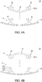
- the correspondingly coupling of encapsulation support structure 3 with the fixed support structure 4 is carried out in such a way that the radius of curvature of the encapsulation portion 31 is smaller than or equal to the radius of curvature of the flexible surface S, so the curvature of the encapsulation portion 31 is greater than or equal to the curvature of the flexible surface S.
- the fixed support structure 4 applies a pre-stress on the encapsulation support structure 3.
- the degree to which the flexible surface S is curved i.e., the curvature
- the radius of curvature of a plane is infinite.
- the fixed support structure 4 includes two first mating components 41.
- each of the first mating components 41 includes, from top to bottom, a head portion, a neck portion and a base portion, wherein the two base portions can be separated from each other or integrally formed.
- the two first mating components 41 become progressively closer to each other as they extend further away from the flexible surface S (i.e., extending in a tapered fashion).
- the encapsulation portion 31 bends towards the direction of the flexible surface S (i.e., the center of the encapsulation portion 31 is closer to the flexible surface S than the two supporting portions 32), and the encapsulation portion 31 can partially touch the flexible surface S or not at all.
- the fixed support structure 4 is attached to the inner surface of a shoe, for example, as shown in FIG. 8 .
- the fixed support structure 4 includes two first mating components 41, each of the first mating components 41 includes a head portion 411, a neck portion 412 and a base portion 413, wherein the two base portions 413 are in principle separated from each other.
- the two first mating components 41 become further apart from each other as they extend further away from the flexible surface S (i.e., extending in a progressively widening fashion).
- the encapsulation portion 31 bends in a direction away from the flexible surface S (i.e., the center of the encapsulation portion 31 is further from the flexible surface S than the two supporting portions 32), and the encapsulation portion 31 can partially touch the flexible surface S or not at all.
- the flexible surface S is deformed (e.g., deformations of the inner surface of the shoe caused by walking)
- mechanical energy is transferred to the encapsulation portion 31 being caused to vibrate, and the carrying structure 2 encapsulated in the encapsulation portion 31 is deformed by this mechanical energy, and the piezoelectric generator 1 converts the mechanical energy to electrical energy.
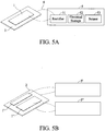
- the self-powered sensing and transmitting device of the present disclosure further includes a circuit module 5 and connectors 6 connecting the circuit module 5 to the piezoelectric generator 1 and the carrying structure 2, wherein the circuit module 5 and the connectors 6 can be encapsulated by the encapsulation portion 31 of the encapsulation support structure 3.
- the circuit module 5 includes a rectifier 51, an electrical storage 52 (e.g., a temporary storage control circuit or a rechargeable battery) and a sensor 53 (e.g., including a sensing module and a signal transmission module).
- the circuit module 5 rectifies and stores the alternating current generated by the piezoelectric generator 1 in the temporary storage control circuit, wherein a voltage regulating IC and a capacitor are used for controlling the output voltage level, and power can then be directly provided from the temporary storage control circuit to the sensing module and the signal transmission module for use.
- the circuit module 5 rectifies and stores the alternating current generated by the piezoelectric generator 1 to the rechargeable battery.
- the piezoelectric generator 1 can be provided as a single unit stacked on the carrying structure 2, as shown in FIG.
- a thin metal plate can be stacked on the piezoelectric generator 1, such that if a crack occurs in the piezoelectric generator 1, electrical conduction with the circuit module 5 can be maintained through the thin metal plate.
- a conductive adhesive can be used for connecting the piezoelectric generator 1, the carrying structure 2 and the circuit module 5 to ensure proper electrical connections between the piezoelectric generator 1, the carrying structure 2 and the circuit module 5 during vibrations of the carrying structure 2.
- an encapsulation conductive adhesive can be used for encapsulating the piezoelectric generator 1 with the circuit module 5, and the carrying structure 2 with the circuit module 5, so as to ensure proper electrical connections with the circuit module 5.
- a circuit with a minimum loss of electrical energy in which the alternating current generated by the piezoelectric generator 1 is rectified and stored in the electrical storage 52 of the circuit module 5 (e.g., a temporary storage control circuit or a rechargeable battery) with a voltage regulating IC and a capacitor for controlling the level of the output voltage, and power is directly provided from the electrical storage 52 for use by a load of the sensor 53 (e.g., including a sensing module and a signal transmitting module).
- the circuit module 5 e.g., a temporary storage control circuit or a rechargeable battery
- a voltage regulating IC and a capacitor for controlling the level of the output voltage
- the piezoelectric generator 1 in order to reduce the risk of puncturing of the device when on the road, can be designed as two separate units, or as two electrode areas cut on the same ultra-thin piezoelectric ceramic to form two separate generators.
- the alternating current generated by one of the piezoelectric generators can be rectified and stored in the electrical storage 52 of the circuit module 5 (e.g., a temporary storage control circuit or a rechargeable battery), and when the G value sensed by the accelerometer is greater than zero (i.e., when vehicle is moving), then the sensor 53 is directly powered by the electrical energy generated by this piezoelectric generator.
- electrical energy generated by the other generator while the vehicle is moving can be inputted into the electrical storage 52 instead of being used to power the load. It only supplies electricity when the vehicle is stationary and detection is required.
- the fixed support structure 4 of the self-powered sensing and transmitting device 10 of the present disclosure can be secured onto the flexible surface S (inner surface of the tire), and the piezoelectric generator 1, the carrying structure 2, the circuit module 5 and the connectors 6 can be encapsulated by the encapsulation support structure 3 as one unit.
- the correspondingly coupling between the supporting portions 32 and the fixed support structure 4 allows the encapsulation portion 31 to have a radius of curvature that is smaller than or equal to the radius of curvature of the flexible surface S, and the encapsulation portion 31 can partially touch the flexible surface S or not at all, so as to create vibrations during deformation of the flexible surface S.
- the electrical storage 52 of the circuit module 5 can be designed to replace disposable batteries.
- the piezoelectric generator 1 that has an adjustable curvature, sufficient electrical energy can be generated to provide the power needed by the sensing module (e.g., the temperature and tire pressure sensors and the accelerometer) and the signal transmission module.
- the self-powered sensing and transmitting device 10 of the present disclosure is applicable to TPMS, and can be designed as a detachable and reusable tire parameter sensing device that can be attached to the inner wall of a tire, and can be removed from the old tire reaching the end of its life and installed on a new tire to be used again.
- the self-powered sensing and transmitting device 10 when the tire 20 starts to rotate, the self-powered sensing and transmitting device 10 receives mechanical energy, and the carrying structure 2 is deformed to cause vibrations in the piezoelectric generator 1.
- the piezoelectric generator 1 already has a radius of curvature smaller than that of the inner wall of the tire.
- the self-powered sensing and transmitting device 10 receives mechanical energy, the carrying structure 2 is deformed to cause vibrations in the piezoelectric generator 1.
- FIG. 6A when the tire 20 starts to rotate, the self-powered sensing and transmitting device 10 receives mechanical energy, and the carrying structure 2 is deformed to cause vibrations in the piezoelectric generator 1.
- the self-powered sensing and transmitting device 10 installed in the inner surface of the tire can provide power to itself in order to perform sensing and signal transmissions.
- the relationships between the thickness the piezoelectric generator and the voltage and current generated are explained using Table 1B below.
- a piezoelectric ceramic with a size of 75 mm*30 mm is used as the piezoelectric generator, and a metal plate with a size of 100 mm*32 mm*0.1 mm (L* W *T) is used as the carrying structure.
- the radius of curvature of the piezoelectric ceramic is 15 cm.
- the piezoelectric generator is connected to a load of 1 k ⁇ , and the load voltage (Vmax) is measured.
- Table 1B Thickness (mm) 0.04 0.07 0.1 0.12 0.15 Voltage (V) 9.3 11.2 14.5 15.1 16.7 Current (mA) 18 15 12 8 7
- the self-powered sensing and transmitting device of the present disclosure is installed in the inner surface of a tire to create a smart tire. More specifically, the fixed support structure of the self-powered sensing and transmitting device is secured to the inner surface of the tire or integrally formed with the tire, and the encapsulation support structure of the self-powered sensing and transmitting device is correspondingly coupled with the fixed support structure to facilitate removal.
- feasibility of the applications of the present disclosure is illustrated below using a standard 16-inch (about 35 cm) sedan tire and a truck tire (about 65 cm).
- the sedan tire is essentially composed of a special rubber embedded with multilayers of steel wire coils, and the truck tire has even more layers of steel wire coils tightly embedded in the rubber, therefore, during testing, signals are transmitted using a radio frequency of 433 MHz for the sedan tire, and using Bluetooth communication method of 2.4 GHz for the truck tire.
- the self-powered sensing and transmitting devices of the present disclosure are installed at the centers of the inner crowns of the tires in conformity with the tires (i.e., with the same radius of curvature).
- the generator used in the sedan tire is a single ultra-thin piezoelectric ceramic with a thickness of 45 ⁇ m; while the generator used in the truck tire is composed of two ultra-thin piezoelectric ceramics (a bimorph) with a same thickness of 45 ⁇ m and a slighter larger area.
- the two piezoelectric ceramics are stacked on the same metal plate as a bimorph to save space. Test conditions start from a standstill and accelerate to a maximum of 120 km/h.
- the tires are run at 30 km/h, 60 km/h, and 120 km/h for 1 hour, respectively.
- Signal receivers are placed ten meters away from the tires and intervals of transmitted signals related to tire pressure, temperature and acceleration are recorded.
- Table 2A Area of Piezoelectric Generator (cm 2 ) Type of Tires Tested (radius of curvature in cm) Static Capacitance ( ⁇ F) Signal Transmission Method 30 km/h Signal Transmission Interval (sec) 60 km/h Signal Transmission Interval (sec) 120 km/h Signal Transmission Interval (sec) 15 cm 2 16 inch Sedan Tire (35 cm) 1 433 MHz (RF) 5 1 1 22 cm 2 *2 (bimorph) Truck Tire (65 cm) 2.3 2.4 GHz 15 8 1
- the receiver receives parameter information sent from the inner tire at an interval of 5 seconds.
- the sedan tire can achieve a signal transmission frequency of once per second.
- the truck tire shows similar trend as the sedan tire.
- the diameter of truck tire is considerably larger, and one revolution of the truck tire is more than 4 meters in length, the intervals between power generation due to the deformations of the sedan tire and truck tire touching the ground at a speed of 30 km/h is found to be 0.264 seconds for the sedan tire and 0.49 seconds for the truck tire.
- the truck tire can also achieve Bluetooth signal transmissions almost once every second.
- Table 2B Area of Piezoelectric Generator (cm 2 ) Type of Tires Tested (radius of curvature in cm) Static Capacitance ( ⁇ F) Signal Transmission Method 30 km/h Signal Transmission Interval (sec) 60 km/h Signal Transmission Interval (sec) 120 km/h Signal Transmission Interval (sec) 15 cm 2 16 inch Sedan Tire (35 cm) 1 433 MHz (RF) 3 1 1 22 cm 2 *2 Truck tire (65 cm) 2.3 2.4 GHz 10 5 1
- the signal transmission interval is shortened to about 3 seconds, which means that the self-powered sensing and transmitting device can still capture slow and small changes in mechanical energy (such as when the vehicle is moving through the city slowly or in a traffic jam), and convert the mechanical energy into power required by the tire sensors and the signal transmitter.
- the results for the truck tire also indicate that the power generation efficiency of the self-powered sensing and transmitting device is improved due to the pre-stress, and as speed increases, the transmission intervals of the Bluetooth signals are greatly reduced to 10 seconds (at 30 km/h), 5 seconds (at 60 km/h) and 1 second (at 120 km/h).
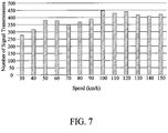
- the much larger generator (22 cm 2 *2 [i.e., bimorph]) is used for testing a sedan tire that is secured in the same way as in the test described with respect to Table 2B, and observations are made on the number of cumulative signal transmissions over a period of time.
- the speed starts from 30 km/h, and is increased to a maximum speed of 150 km/h sequentially with the duration of each speed being 5 minutes (300 seconds).
- the results are shown in FIG. 7 .
- the number of signal transmissions is increased since the area of the generator is larger.
- the sedan tire is running at low speeds (30-40 km/h), it can transmit tire pressure signals nearly once every second, and as the speed increases, the signal transmission intervals are less than one second in the higher speed range.
- the total test duration is 3900 seconds from the lowest to the highest speeds, and the receiver receives a total of 5017 signals.
- sending tire pressure signals once per second, or even less than one second can provide continuous detections of the tire pressure status.
- the detection frequency provided by the self-powered sensing and transmitting device of the present disclosure is significantly higher. This increases the safety factor. For example, if the tire is punctured when on the road, tire pressure will leak quickly. With the self-powered sensing and transmitting device of the present disclosure, it will be possible to accurately determine the tire pressure in real time whether the tire is studded or punctured by a foreign object.
- the encapsulation support structure of the self-powered sensing and transmitting device can be removed from the fixed support structure. After another tire provided with a fixed support structure is fitted, the encapsulation support structure can then be correspondingly coupled to the fixed support structure of the new tire for further sensing of tire pressure, temperature, acceleration, etc.
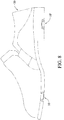
- a system includes a plurality of the self-powered sensing and transmitting devices 10, 10', wherein one of one or more self-powered sensing and transmitting devices 10, 10' is provided on the inner surface of the shoe 30 near a toe of the shoe 30, and another one of the self-powered sensing and transmitting devices 10, 10' is provided on the inner surface of the shoe 30 near a heel of the shoe 30, and wherein one of the encapsulation portions of the encapsulation support structures of the one or more self-powered sensing and transmitting devices 10, 10' is curved in an opposite direction to the encapsulation portion of the encapsulation support structure of the another one self-powered sensing and transmitting device 10 or 10'.
- the self-powered sensing and transmitting device 10 or 10' can be installed on the inner surface of a shoe 30.
- a smart shoe can be provided, in which the self-powered sensing and transmitting device 10 or 10' of the present disclosure can be disposed on the inner surface of the shoe 30 near the toe, sole, heel or other areas of a human foot in order to output sensed data related to the foot, e.g., weight, walking or running status, steps taken or distances travelled during an motion, etc.
- the self-powered sensing and transmitting device 10 is provided on the inner surface of the shoe 30 near the toe or sole area
- the self-powered sensing and transmitting device 10' is provided on the inner surface of the shoe 30 near the heel area.
- the radius of curvature of the encapsulation support structure in the self-powered sensing and transmitting device 10 or 10' is smaller than or equal to that of the bottom surface of the shoe where the self-powered sensing and transmitting device 10 or 10' is located, and the bending direction of the encapsulation support structure can be opposite to or the same as that of the bottom surface of the shoe.
- the self-powered sensing and transmitting device of the present disclosure is applied to a motion monitoring system, and the self-powered sensing and transmitting devices 10 and 10' are installed on the inner surface (i.e., the flexible surface S) of the shoe 30, one of the self-powered sensing and transmitting devices (shown as the self-powered sensing and transmitting device 10 in FIG. 8 ) is provided on the inner surface of the shoe near the toe of the shoe, whereas the other one of the self-powered sensing and transmitting devices (shown as the self-powered sensing and transmitting device 10' in FIG.
- the encapsulation portion of the encapsulation support structure of the one self-powered sensing and transmitting device is curved in the opposite direction to the encapsulation portion of the encapsulation support structure of the other one self-powered sensing and transmitting device.
- the self-powered sensing and transmitting device of the present disclosure is a detachable and reusable device attached to, for example, the inner surface of a tire or the inner bottom surface of a shoe for sensing tire or motion parameters.
- the sensing module for sensing temperature, pressure, acceleration, etc.
- the self-powered sensing and transmitting device of the present disclosure captures the changes in mechanical energy from the tire (shoe) in contact with the ground using an ultra-thin piezoelectric ceramic capable of converting mechanical energy to electrical energy.
- the ultra-thin piezoelectric ceramic attached to the inner surface of the tire (or the inner bottom surface of the shoe) has a radius of curvature smaller than or equal to that of the inner surface of the tire (or the inner bottom surface of the shoe).
- the self-powered sensing and transmitting device of the present disclosure can also be detached and reused, so when a tire has reached the end of its life, the self-powered sensing and transmitting device can be reinstalled on a new tire, which is both environmental friendly and economical.
Landscapes
- Engineering & Computer Science (AREA)
- Mechanical Engineering (AREA)
- Microelectronics & Electronic Packaging (AREA)
- Force Measurement Appropriate To Specific Purposes (AREA)
- General Electrical Machinery Utilizing Piezoelectricity, Electrostriction Or Magnetostriction (AREA)
- Measuring Pulse, Heart Rate, Blood Pressure Or Blood Flow (AREA)
- Geophysics And Detection Of Objects (AREA)
- Tires In General (AREA)
Applications Claiming Priority (1)
| Application Number | Priority Date | Filing Date | Title |
|---|---|---|---|
| US201962941017P | 2019-11-27 | 2019-11-27 |
Publications (2)
| Publication Number | Publication Date |
|---|---|
| EP3828013A1 true EP3828013A1 (de) | 2021-06-02 |
| EP3828013B1 EP3828013B1 (de) | 2023-09-27 |
Family
ID=73834134
Family Applications (1)
| Application Number | Title | Priority Date | Filing Date |
|---|---|---|---|
| EP20000428.1A Active EP3828013B1 (de) | 2019-11-27 | 2020-11-25 | Selbstgetriebene erfassungs- und übertragungsvorrichtung |
Country Status (5)
| Country | Link |
|---|---|
| US (1) | US11919336B2 (de) |
| EP (1) | EP3828013B1 (de) |
| JP (1) | JP7270590B2 (de) |
| CN (2) | CN214057141U (de) |
| TW (2) | TWI771808B (de) |
Cited By (1)
| Publication number | Priority date | Publication date | Assignee | Title |
|---|---|---|---|---|
| WO2022033842A3 (de) * | 2020-08-13 | 2022-09-22 | Tdk Electronics Ag | Piezoelektrischer wandler mit verkapselung und verfahren zur einstellung der elektromechanischen eigenschaften des piezoelektrischen wandlers |
Families Citing this family (4)
| Publication number | Priority date | Publication date | Assignee | Title |
|---|---|---|---|---|
| DE102018221053A1 (de) * | 2018-04-05 | 2019-10-10 | Continental Reifen Deutschland Gmbh | Vorrichtung zum Messen einer mechanischen Kraft, umfassend eine erste, zweite, dritte, vierte und fünfte Schicht sowie die Verwendungen der Vorrichtung und Reifen oder technischer Gummiartikel umfassend die Vorrichtung |
| CN214057141U (zh) | 2019-11-27 | 2021-08-27 | 财团法人工业技术研究院 | 发电感测传输装置 |
| TWI777704B (zh) * | 2021-07-30 | 2022-09-11 | 建大工業股份有限公司 | 設置有感測器之輪胎(二) |
| EP4556260A1 (de) * | 2023-11-16 | 2025-05-21 | Nxp B.V. | Uwb-reifenüberwachungssensor, system und zugehöriges verfahren |
Citations (4)
| Publication number | Priority date | Publication date | Assignee | Title |
|---|---|---|---|---|
| WO1999041093A1 (en) * | 1998-02-12 | 1999-08-19 | Michelin Recherche Et Technique S.A. | Attachment means for a tire electronic package |
| EP1614552A1 (de) * | 2004-07-09 | 2006-01-11 | Société de Technologie Michelin | Brückenförmige Halterung für elektromechanische Wandler in Reifen |
| US20060021261A1 (en) * | 2004-07-19 | 2006-02-02 | Face Bradbury R | Footwear incorporating piezoelectric energy harvesting system |
| US20130181578A1 (en) * | 2010-07-02 | 2013-07-18 | Murata Manufacturing Co., Ltd. | Piezoelectric Power Generator |
Family Cites Families (33)
| Publication number | Priority date | Publication date | Assignee | Title |
|---|---|---|---|---|
| AU536679B2 (en) * | 1979-11-27 | 1984-05-17 | Imperial Clevite Inc. | Vibrating transducer power supply in abnormal tire condition warning systems |
| US5869189A (en) | 1994-04-19 | 1999-02-09 | Massachusetts Institute Of Technology | Composites for structural control |
| FR2745476B1 (fr) * | 1996-03-01 | 1998-04-03 | Thomson Csf | Semelles de chaussure a recuperation d'energie |
| US5781104A (en) * | 1996-12-23 | 1998-07-14 | Huang; Tien-Tsai | Pressure gauge with self-generating power capability for a tire pressure indicator |
| BR9916272A (pt) | 1998-12-17 | 2001-09-04 | Hoffmann La Roche | 4 e 5-alquiniloxindóis e 4 e 5-alqueniloxindóis |
| US6629341B2 (en) * | 1999-10-29 | 2003-10-07 | The United States Of America As Represented By The Administrator Of The National Aeronautics And Space Administration | Method of fabricating a piezoelectric composite apparatus |
| US6885291B1 (en) * | 1999-11-15 | 2005-04-26 | The Goodyear Tire & Rubber Company | Mouting transponders and antennas in pneumatic tires |
| DE10203024B4 (de) | 2002-01-26 | 2009-11-26 | Robert Bosch Gmbh | Verfahren zur Herstellung eines Keramiksubstrats |
| US7096727B2 (en) | 2002-05-10 | 2006-08-29 | Michelin Recherche Et Technique S.A. | System and method for generating electric power from a rotating tire's mechanical energy |
| US6725713B2 (en) | 2002-05-10 | 2004-04-27 | Michelin & Recherche Et Technique S.A. | System for generating electric power from a rotating tire's mechanical energy using reinforced piezoelectric materials |
| JP2004053329A (ja) * | 2002-07-18 | 2004-02-19 | Hitachi Ltd | 半導体センサ組み立て体およびタイヤモニタセンサ |
| KR100555659B1 (ko) * | 2003-12-22 | 2006-03-03 | 삼성전자주식회사 | 자가발전형 센싱 모듈 및 그것을 사용하는 타이어 공기압모니터링 시스템 |
| US7047800B2 (en) | 2004-06-10 | 2006-05-23 | Michelin Recherche Et Technique S.A. | Piezoelectric ceramic fibers having metallic cores |
| KR100698438B1 (ko) | 2005-05-18 | 2007-03-22 | 한국과학기술연구원 | 변위 확대 기구를 갖는 압전 선형 모터 |
| US7343787B2 (en) * | 2005-05-19 | 2008-03-18 | Oguzhan Oflaz | Piezoelectric tire sensor and method |
| JP4778786B2 (ja) | 2005-12-12 | 2011-09-21 | 株式会社ブリヂストン | 電子装置取付構造、及び空気入りタイヤ |
| FR2899150B1 (fr) | 2006-04-04 | 2010-09-10 | Michelin Soc Tech | Dispositif de fixation d'un module sur la paroi interne d'un pneumatique |
| US7523656B1 (en) | 2007-11-01 | 2009-04-28 | Infineon Technologies Ag | Tire sensor system and monitoring method |
| DE102008007774A1 (de) * | 2008-02-06 | 2009-08-13 | Robert Bosch Gmbh | Biegewandler zum Erzeugen von elektrischer Energie aus mechanischen Verformungen |
| JP5819047B2 (ja) | 2010-07-27 | 2015-11-18 | 横浜ゴム株式会社 | 空気入りタイヤ |
| TWM396766U (en) | 2010-09-03 | 2011-01-21 | Univ Kao Yuan | Wireless-tire pressure sensor with piezoelectric power generation |
| CN102069686B (zh) | 2010-12-14 | 2012-11-28 | 吉林大学 | 基于有机压电材料的汽车轮胎监测装置 |
| WO2013153088A1 (de) | 2012-04-11 | 2013-10-17 | Huf Hülsbeck & Fürst Gmbh & Co. Kg | Reifenmodul mit piezoelektrischem wandler und damit ausgestatteter reifen |
| JP5837851B2 (ja) | 2012-04-24 | 2015-12-24 | 株式会社ブリヂストン | 空気入りタイヤ内面への電子部品取付構造 |
| TWI584975B (zh) | 2013-10-31 | 2017-06-01 | 國立臺灣師範大學 | Transportation |
| CN105099264A (zh) | 2014-05-04 | 2015-11-25 | 闫世伟 | 一种压电发电装置及其应用 |
| CN104337107A (zh) | 2014-11-15 | 2015-02-11 | 达宁 | 基于压电材料的人体动能供电智能鞋 |
| US10035385B2 (en) | 2015-03-03 | 2018-07-31 | The Goodyear Tire & Rubber Company | Tire producing electrical power |
| CN107471927A (zh) | 2016-06-08 | 2017-12-15 | 滴滴(中国)科技有限公司 | 一种基于压电陶瓷的胎压监测装置、轮胎和车辆 |
| JP7014495B2 (ja) | 2017-03-22 | 2022-02-01 | ムネカタ株式会社 | 発電インソール |
| CN208544059U (zh) | 2018-07-12 | 2019-02-26 | 江苏通用科技股份有限公司 | 一种轮胎结构 |
| CN109738095A (zh) | 2018-12-18 | 2019-05-10 | 中北大学 | 柔性可穿戴传感器及其相应的可穿戴设备以及制备方法 |
| CN214057141U (zh) | 2019-11-27 | 2021-08-27 | 财团法人工业技术研究院 | 发电感测传输装置 |
-
2020
- 2020-11-25 CN CN202022763290.9U patent/CN214057141U/zh active Active
- 2020-11-25 JP JP2020195269A patent/JP7270590B2/ja active Active
- 2020-11-25 US US17/104,214 patent/US11919336B2/en active Active
- 2020-11-25 TW TW109141302A patent/TWI771808B/zh active
- 2020-11-25 TW TW109215540U patent/TWM609142U/zh unknown
- 2020-11-25 EP EP20000428.1A patent/EP3828013B1/de active Active
- 2020-11-25 CN CN202011336843.0A patent/CN112848815A/zh active Pending
Patent Citations (4)
| Publication number | Priority date | Publication date | Assignee | Title |
|---|---|---|---|---|
| WO1999041093A1 (en) * | 1998-02-12 | 1999-08-19 | Michelin Recherche Et Technique S.A. | Attachment means for a tire electronic package |
| EP1614552A1 (de) * | 2004-07-09 | 2006-01-11 | Société de Technologie Michelin | Brückenförmige Halterung für elektromechanische Wandler in Reifen |
| US20060021261A1 (en) * | 2004-07-19 | 2006-02-02 | Face Bradbury R | Footwear incorporating piezoelectric energy harvesting system |
| US20130181578A1 (en) * | 2010-07-02 | 2013-07-18 | Murata Manufacturing Co., Ltd. | Piezoelectric Power Generator |
Cited By (1)
| Publication number | Priority date | Publication date | Assignee | Title |
|---|---|---|---|---|
| WO2022033842A3 (de) * | 2020-08-13 | 2022-09-22 | Tdk Electronics Ag | Piezoelektrischer wandler mit verkapselung und verfahren zur einstellung der elektromechanischen eigenschaften des piezoelektrischen wandlers |
Also Published As
| Publication number | Publication date |
|---|---|
| TW202120349A (zh) | 2021-06-01 |
| CN214057141U (zh) | 2021-08-27 |
| US11919336B2 (en) | 2024-03-05 |
| CN112848815A (zh) | 2021-05-28 |
| JP2021101606A (ja) | 2021-07-08 |
| US20210155059A1 (en) | 2021-05-27 |
| JP7270590B2 (ja) | 2023-05-10 |
| EP3828013B1 (de) | 2023-09-27 |
| TWI771808B (zh) | 2022-07-21 |
| TWM609142U (zh) | 2021-03-11 |
Similar Documents
| Publication | Publication Date | Title |
|---|---|---|
| EP3828013B1 (de) | Selbstgetriebene erfassungs- und übertragungsvorrichtung | |
| RU2377137C2 (ru) | Система для генерирования электрической энергии из механической энергии вращающейся шины | |
| CN104302490B (zh) | 轮胎模块以及配备了该模块的轮胎 | |
| US8578767B2 (en) | Tire module and tires equipped therewith | |
| CN100368214C (zh) | 遥测装置 | |
| US11148480B2 (en) | Tire assembly, tire monitoring system, and tire monitoring method | |
| RU2388621C2 (ru) | Сборка шины со встроенными устройствами для генерирования электроэнергии | |
| US20210370727A1 (en) | Functional component, structure for attaching functional component to tire, and tire | |
| JP2005525265A5 (de) | ||
| CN1549776A (zh) | 利用增强压电材料从旋转轮胎机械能量中产生电能的系统 | |
| CN1716748A (zh) | 来自压电电源的电能转换 | |
| EP1800912A1 (de) | Vorrichtung zur übertragung von reifeninformationen, vorrichtung zur erfassung von reifeninformationen und reifen/radanordnung | |
| EP2863445A1 (de) | Verfahren und Vorrichtung zur Einstellung des elektrischen Spalts für einen piezoelektrischen Drucksensor | |
| EP2113953A1 (de) | Verbesserungen bei oder im Zusammenhang mit Energieumwandlung | |
| EP2415619A1 (de) | Eigenbetriebenes Sensormodul und System zur Überwachung der Zustände von Reifen eines Fahrzeugs mit mindestens einem eigenbetriebenen Sensormodul | |
| US12235102B2 (en) | Measuring device and measuring system | |
| CN110367994B (zh) | 压电矩阵主动监测步态装置及其工作方法 | |
| CN214355379U (zh) | 一种无电池胎压监测电路及监测系统 | |
| CN102922961A (zh) | 一种电容式微型胎压传感器 | |
| CN206049260U (zh) | 一种胎压监测系统 | |
| KR102161571B1 (ko) | 압전소자를 이용한 자가발전기 | |
| JPH05233903A (ja) | 一次電池内蔵icカードの電池寿命延命化方式 | |
| WO2020235415A1 (ja) | タイヤ監視システム用の電源、タイヤ監視システム及びタイヤ組立体 | |
| CN112373251A (zh) | 一种无电池胎压监测电路、监测系统及监测方法 |
Legal Events
| Date | Code | Title | Description |
|---|---|---|---|
| PUAI | Public reference made under article 153(3) epc to a published international application that has entered the european phase |
Free format text: ORIGINAL CODE: 0009012 |
|
| STAA | Information on the status of an ep patent application or granted ep patent |
Free format text: STATUS: THE APPLICATION HAS BEEN PUBLISHED |
|
| AK | Designated contracting states |
Kind code of ref document: A1 Designated state(s): AL AT BE BG CH CY CZ DE DK EE ES FI FR GB GR HR HU IE IS IT LI LT LU LV MC MK MT NL NO PL PT RO RS SE SI SK SM TR |
|
| STAA | Information on the status of an ep patent application or granted ep patent |
Free format text: STATUS: REQUEST FOR EXAMINATION WAS MADE |
|
| 17P | Request for examination filed |
Effective date: 20210706 |
|
| RBV | Designated contracting states (corrected) |
Designated state(s): AL AT BE BG CH CY CZ DE DK EE ES FI FR GB GR HR HU IE IS IT LI LT LU LV MC MK MT NL NO PL PT RO RS SE SI SK SM TR |
|
| RIC1 | Information provided on ipc code assigned before grant |
Ipc: H10N 30/88 20230101ALI20230227BHEP Ipc: H10N 30/30 20230101ALI20230227BHEP Ipc: H02N 2/18 20060101ALI20230227BHEP Ipc: B29D 30/00 20060101ALI20230227BHEP Ipc: A43B 3/00 20060101ALI20230227BHEP Ipc: B60C 23/04 20060101AFI20230227BHEP |
|
| GRAP | Despatch of communication of intention to grant a patent |
Free format text: ORIGINAL CODE: EPIDOSNIGR1 |
|
| STAA | Information on the status of an ep patent application or granted ep patent |
Free format text: STATUS: GRANT OF PATENT IS INTENDED |
|
| RAP3 | Party data changed (applicant data changed or rights of an application transferred) |
Owner name: INDUSTRIAL TECHNOLOGY RESEARCH INSTITUTE |
|
| INTG | Intention to grant announced |
Effective date: 20230419 |
|
| GRAS | Grant fee paid |
Free format text: ORIGINAL CODE: EPIDOSNIGR3 |
|
| GRAA | (expected) grant |
Free format text: ORIGINAL CODE: 0009210 |
|
| STAA | Information on the status of an ep patent application or granted ep patent |
Free format text: STATUS: THE PATENT HAS BEEN GRANTED |
|
| AK | Designated contracting states |
Kind code of ref document: B1 Designated state(s): AL AT BE BG CH CY CZ DE DK EE ES FI FR GB GR HR HU IE IS IT LI LT LU LV MC MK MT NL NO PL PT RO RS SE SI SK SM TR |
|
| REG | Reference to a national code |
Ref country code: GB Ref legal event code: FG4D |
|
| REG | Reference to a national code |
Ref country code: CH Ref legal event code: EP |
|
| REG | Reference to a national code |
Ref country code: DE Ref legal event code: R096 Ref document number: 602020018100 Country of ref document: DE |
|
| REG | Reference to a national code |
Ref country code: IE Ref legal event code: FG4D |
|
| REG | Reference to a national code |
Ref country code: LT Ref legal event code: MG9D |
|
| PG25 | Lapsed in a contracting state [announced via postgrant information from national office to epo] |
Ref country code: GR Free format text: LAPSE BECAUSE OF FAILURE TO SUBMIT A TRANSLATION OF THE DESCRIPTION OR TO PAY THE FEE WITHIN THE PRESCRIBED TIME-LIMIT Effective date: 20231228 |
|
| PG25 | Lapsed in a contracting state [announced via postgrant information from national office to epo] |
Ref country code: SE Free format text: LAPSE BECAUSE OF FAILURE TO SUBMIT A TRANSLATION OF THE DESCRIPTION OR TO PAY THE FEE WITHIN THE PRESCRIBED TIME-LIMIT Effective date: 20230927 Ref country code: RS Free format text: LAPSE BECAUSE OF FAILURE TO SUBMIT A TRANSLATION OF THE DESCRIPTION OR TO PAY THE FEE WITHIN THE PRESCRIBED TIME-LIMIT Effective date: 20230927 Ref country code: NO Free format text: LAPSE BECAUSE OF FAILURE TO SUBMIT A TRANSLATION OF THE DESCRIPTION OR TO PAY THE FEE WITHIN THE PRESCRIBED TIME-LIMIT Effective date: 20231227 Ref country code: LV Free format text: LAPSE BECAUSE OF FAILURE TO SUBMIT A TRANSLATION OF THE DESCRIPTION OR TO PAY THE FEE WITHIN THE PRESCRIBED TIME-LIMIT Effective date: 20230927 Ref country code: LT Free format text: LAPSE BECAUSE OF FAILURE TO SUBMIT A TRANSLATION OF THE DESCRIPTION OR TO PAY THE FEE WITHIN THE PRESCRIBED TIME-LIMIT Effective date: 20230927 Ref country code: HR Free format text: LAPSE BECAUSE OF FAILURE TO SUBMIT A TRANSLATION OF THE DESCRIPTION OR TO PAY THE FEE WITHIN THE PRESCRIBED TIME-LIMIT Effective date: 20230927 Ref country code: GR Free format text: LAPSE BECAUSE OF FAILURE TO SUBMIT A TRANSLATION OF THE DESCRIPTION OR TO PAY THE FEE WITHIN THE PRESCRIBED TIME-LIMIT Effective date: 20231228 Ref country code: FI Free format text: LAPSE BECAUSE OF FAILURE TO SUBMIT A TRANSLATION OF THE DESCRIPTION OR TO PAY THE FEE WITHIN THE PRESCRIBED TIME-LIMIT Effective date: 20230927 |
|
| REG | Reference to a national code |
Ref country code: NL Ref legal event code: MP Effective date: 20230927 |
|
| REG | Reference to a national code |
Ref country code: AT Ref legal event code: MK05 Ref document number: 1615066 Country of ref document: AT Kind code of ref document: T Effective date: 20230927 |
|
| PG25 | Lapsed in a contracting state [announced via postgrant information from national office to epo] |
Ref country code: NL Free format text: LAPSE BECAUSE OF FAILURE TO SUBMIT A TRANSLATION OF THE DESCRIPTION OR TO PAY THE FEE WITHIN THE PRESCRIBED TIME-LIMIT Effective date: 20230927 |
|
| PG25 | Lapsed in a contracting state [announced via postgrant information from national office to epo] |
Ref country code: IS Free format text: LAPSE BECAUSE OF FAILURE TO SUBMIT A TRANSLATION OF THE DESCRIPTION OR TO PAY THE FEE WITHIN THE PRESCRIBED TIME-LIMIT Effective date: 20240127 |
|
| PG25 | Lapsed in a contracting state [announced via postgrant information from national office to epo] |
Ref country code: AT Free format text: LAPSE BECAUSE OF FAILURE TO SUBMIT A TRANSLATION OF THE DESCRIPTION OR TO PAY THE FEE WITHIN THE PRESCRIBED TIME-LIMIT Effective date: 20230927 |
|
| PG25 | Lapsed in a contracting state [announced via postgrant information from national office to epo] |
Ref country code: ES Free format text: LAPSE BECAUSE OF FAILURE TO SUBMIT A TRANSLATION OF THE DESCRIPTION OR TO PAY THE FEE WITHIN THE PRESCRIBED TIME-LIMIT Effective date: 20230927 |
|
| PG25 | Lapsed in a contracting state [announced via postgrant information from national office to epo] |
Ref country code: SM Free format text: LAPSE BECAUSE OF FAILURE TO SUBMIT A TRANSLATION OF THE DESCRIPTION OR TO PAY THE FEE WITHIN THE PRESCRIBED TIME-LIMIT Effective date: 20230927 Ref country code: RO Free format text: LAPSE BECAUSE OF FAILURE TO SUBMIT A TRANSLATION OF THE DESCRIPTION OR TO PAY THE FEE WITHIN THE PRESCRIBED TIME-LIMIT Effective date: 20230927 Ref country code: IS Free format text: LAPSE BECAUSE OF FAILURE TO SUBMIT A TRANSLATION OF THE DESCRIPTION OR TO PAY THE FEE WITHIN THE PRESCRIBED TIME-LIMIT Effective date: 20240127 Ref country code: ES Free format text: LAPSE BECAUSE OF FAILURE TO SUBMIT A TRANSLATION OF THE DESCRIPTION OR TO PAY THE FEE WITHIN THE PRESCRIBED TIME-LIMIT Effective date: 20230927 Ref country code: EE Free format text: LAPSE BECAUSE OF FAILURE TO SUBMIT A TRANSLATION OF THE DESCRIPTION OR TO PAY THE FEE WITHIN THE PRESCRIBED TIME-LIMIT Effective date: 20230927 Ref country code: CZ Free format text: LAPSE BECAUSE OF FAILURE TO SUBMIT A TRANSLATION OF THE DESCRIPTION OR TO PAY THE FEE WITHIN THE PRESCRIBED TIME-LIMIT Effective date: 20230927 Ref country code: AT Free format text: LAPSE BECAUSE OF FAILURE TO SUBMIT A TRANSLATION OF THE DESCRIPTION OR TO PAY THE FEE WITHIN THE PRESCRIBED TIME-LIMIT Effective date: 20230927 Ref country code: PT Free format text: LAPSE BECAUSE OF FAILURE TO SUBMIT A TRANSLATION OF THE DESCRIPTION OR TO PAY THE FEE WITHIN THE PRESCRIBED TIME-LIMIT Effective date: 20240129 Ref country code: SK Free format text: LAPSE BECAUSE OF FAILURE TO SUBMIT A TRANSLATION OF THE DESCRIPTION OR TO PAY THE FEE WITHIN THE PRESCRIBED TIME-LIMIT Effective date: 20230927 |
|
| PG25 | Lapsed in a contracting state [announced via postgrant information from national office to epo] |
Ref country code: PL Free format text: LAPSE BECAUSE OF FAILURE TO SUBMIT A TRANSLATION OF THE DESCRIPTION OR TO PAY THE FEE WITHIN THE PRESCRIBED TIME-LIMIT Effective date: 20230927 Ref country code: IT Free format text: LAPSE BECAUSE OF FAILURE TO SUBMIT A TRANSLATION OF THE DESCRIPTION OR TO PAY THE FEE WITHIN THE PRESCRIBED TIME-LIMIT Effective date: 20230927 |
|
| REG | Reference to a national code |
Ref country code: DE Ref legal event code: R097 Ref document number: 602020018100 Country of ref document: DE Ref country code: CH Ref legal event code: PL |
|
| PG25 | Lapsed in a contracting state [announced via postgrant information from national office to epo] |
Ref country code: MC Free format text: LAPSE BECAUSE OF FAILURE TO SUBMIT A TRANSLATION OF THE DESCRIPTION OR TO PAY THE FEE WITHIN THE PRESCRIBED TIME-LIMIT Effective date: 20230927 |
|
| PG25 | Lapsed in a contracting state [announced via postgrant information from national office to epo] |
Ref country code: DK Free format text: LAPSE BECAUSE OF FAILURE TO SUBMIT A TRANSLATION OF THE DESCRIPTION OR TO PAY THE FEE WITHIN THE PRESCRIBED TIME-LIMIT Effective date: 20230927 |
|
| PG25 | Lapsed in a contracting state [announced via postgrant information from national office to epo] |
Ref country code: LU Free format text: LAPSE BECAUSE OF NON-PAYMENT OF DUE FEES Effective date: 20231125 |
|
| PG25 | Lapsed in a contracting state [announced via postgrant information from national office to epo] |
Ref country code: CH Free format text: LAPSE BECAUSE OF NON-PAYMENT OF DUE FEES Effective date: 20231130 |
|
| PG25 | Lapsed in a contracting state [announced via postgrant information from national office to epo] |
Ref country code: MC Free format text: LAPSE BECAUSE OF FAILURE TO SUBMIT A TRANSLATION OF THE DESCRIPTION OR TO PAY THE FEE WITHIN THE PRESCRIBED TIME-LIMIT Effective date: 20230927 Ref country code: LU Free format text: LAPSE BECAUSE OF NON-PAYMENT OF DUE FEES Effective date: 20231125 Ref country code: DK Free format text: LAPSE BECAUSE OF FAILURE TO SUBMIT A TRANSLATION OF THE DESCRIPTION OR TO PAY THE FEE WITHIN THE PRESCRIBED TIME-LIMIT Effective date: 20230927 Ref country code: CH Free format text: LAPSE BECAUSE OF NON-PAYMENT OF DUE FEES Effective date: 20231130 |
|
| REG | Reference to a national code |
Ref country code: BE Ref legal event code: MM Effective date: 20231130 |
|
| PLBE | No opposition filed within time limit |
Free format text: ORIGINAL CODE: 0009261 |
|
| STAA | Information on the status of an ep patent application or granted ep patent |
Free format text: STATUS: NO OPPOSITION FILED WITHIN TIME LIMIT |
|
| 26N | No opposition filed |
Effective date: 20240628 |
|
| REG | Reference to a national code |
Ref country code: IE Ref legal event code: MM4A |
|
| PG25 | Lapsed in a contracting state [announced via postgrant information from national office to epo] |
Ref country code: IE Free format text: LAPSE BECAUSE OF NON-PAYMENT OF DUE FEES Effective date: 20231125 |
|
| PG25 | Lapsed in a contracting state [announced via postgrant information from national office to epo] |
Ref country code: BE Free format text: LAPSE BECAUSE OF NON-PAYMENT OF DUE FEES Effective date: 20231130 |
|
| PG25 | Lapsed in a contracting state [announced via postgrant information from national office to epo] |
Ref country code: SI Free format text: LAPSE BECAUSE OF FAILURE TO SUBMIT A TRANSLATION OF THE DESCRIPTION OR TO PAY THE FEE WITHIN THE PRESCRIBED TIME-LIMIT Effective date: 20230927 |
|
| PG25 | Lapsed in a contracting state [announced via postgrant information from national office to epo] |
Ref country code: SI Free format text: LAPSE BECAUSE OF FAILURE TO SUBMIT A TRANSLATION OF THE DESCRIPTION OR TO PAY THE FEE WITHIN THE PRESCRIBED TIME-LIMIT Effective date: 20230927 Ref country code: IE Free format text: LAPSE BECAUSE OF NON-PAYMENT OF DUE FEES Effective date: 20231125 Ref country code: BE Free format text: LAPSE BECAUSE OF NON-PAYMENT OF DUE FEES Effective date: 20231130 |
|
| PG25 | Lapsed in a contracting state [announced via postgrant information from national office to epo] |
Ref country code: BG Free format text: LAPSE BECAUSE OF FAILURE TO SUBMIT A TRANSLATION OF THE DESCRIPTION OR TO PAY THE FEE WITHIN THE PRESCRIBED TIME-LIMIT Effective date: 20230927 |
|
| PG25 | Lapsed in a contracting state [announced via postgrant information from national office to epo] |
Ref country code: BG Free format text: LAPSE BECAUSE OF FAILURE TO SUBMIT A TRANSLATION OF THE DESCRIPTION OR TO PAY THE FEE WITHIN THE PRESCRIBED TIME-LIMIT Effective date: 20230927 |
|
| PG25 | Lapsed in a contracting state [announced via postgrant information from national office to epo] |
Ref country code: CY Free format text: LAPSE BECAUSE OF FAILURE TO SUBMIT A TRANSLATION OF THE DESCRIPTION OR TO PAY THE FEE WITHIN THE PRESCRIBED TIME-LIMIT; INVALID AB INITIO Effective date: 20201125 |
|
| PG25 | Lapsed in a contracting state [announced via postgrant information from national office to epo] |
Ref country code: HU Free format text: LAPSE BECAUSE OF FAILURE TO SUBMIT A TRANSLATION OF THE DESCRIPTION OR TO PAY THE FEE WITHIN THE PRESCRIBED TIME-LIMIT; INVALID AB INITIO Effective date: 20201125 |
|
| PG25 | Lapsed in a contracting state [announced via postgrant information from national office to epo] |
Ref country code: TR Free format text: LAPSE BECAUSE OF FAILURE TO SUBMIT A TRANSLATION OF THE DESCRIPTION OR TO PAY THE FEE WITHIN THE PRESCRIBED TIME-LIMIT Effective date: 20230927 |
|
| PGFP | Annual fee paid to national office [announced via postgrant information from national office to epo] |
Ref country code: DE Payment date: 20251128 Year of fee payment: 6 |
|
| PGFP | Annual fee paid to national office [announced via postgrant information from national office to epo] |
Ref country code: GB Payment date: 20251127 Year of fee payment: 6 |
|
| PGFP | Annual fee paid to national office [announced via postgrant information from national office to epo] |
Ref country code: FR Payment date: 20251125 Year of fee payment: 6 |