EP3828078B1 - Gasturbinentriebwerk, dessen triebwerksgondel und verfahren zum betrieb eines gasturbinentriebwerks - Google Patents
Gasturbinentriebwerk, dessen triebwerksgondel und verfahren zum betrieb eines gasturbinentriebwerks Download PDFInfo
- Publication number
- EP3828078B1 EP3828078B1 EP20210487.3A EP20210487A EP3828078B1 EP 3828078 B1 EP3828078 B1 EP 3828078B1 EP 20210487 A EP20210487 A EP 20210487A EP 3828078 B1 EP3828078 B1 EP 3828078B1
- Authority
- EP
- European Patent Office
- Prior art keywords
- turbofan engine
- duct
- inlet
- nacelle
- engine nacelle
- Prior art date
- Legal status (The legal status is an assumption and is not a legal conclusion. Google has not performed a legal analysis and makes no representation as to the accuracy of the status listed.)
- Active
Links
Images

Classifications
-
- B—PERFORMING OPERATIONS; TRANSPORTING
- B64—AIRCRAFT; AVIATION; COSMONAUTICS
- B64D—EQUIPMENT FOR FITTING IN OR TO AIRCRAFT; FLIGHT SUITS; PARACHUTES; ARRANGEMENT OR MOUNTING OF POWER PLANTS OR PROPULSION TRANSMISSIONS IN AIRCRAFT
- B64D33/00—Arrangement in aircraft of power plant parts or auxiliaries not otherwise provided for
- B64D33/02—Arrangement in aircraft of power plant parts or auxiliaries not otherwise provided for of combustion air intakes
-
- B—PERFORMING OPERATIONS; TRANSPORTING
- B64—AIRCRAFT; AVIATION; COSMONAUTICS
- B64C—AEROPLANES; HELICOPTERS
- B64C23/00—Influencing air flow over aircraft surfaces, not otherwise provided for
- B64C23/06—Influencing air flow over aircraft surfaces, not otherwise provided for by generating vortices
-
- B—PERFORMING OPERATIONS; TRANSPORTING
- B64—AIRCRAFT; AVIATION; COSMONAUTICS
- B64D—EQUIPMENT FOR FITTING IN OR TO AIRCRAFT; FLIGHT SUITS; PARACHUTES; ARRANGEMENT OR MOUNTING OF POWER PLANTS OR PROPULSION TRANSMISSIONS IN AIRCRAFT
- B64D15/00—De-icing or preventing icing on exterior surfaces of aircraft
- B64D15/02—De-icing or preventing icing on exterior surfaces of aircraft by ducted hot gas or liquid
- B64D15/04—Hot gas application
-
- B—PERFORMING OPERATIONS; TRANSPORTING
- B64—AIRCRAFT; AVIATION; COSMONAUTICS
- B64D—EQUIPMENT FOR FITTING IN OR TO AIRCRAFT; FLIGHT SUITS; PARACHUTES; ARRANGEMENT OR MOUNTING OF POWER PLANTS OR PROPULSION TRANSMISSIONS IN AIRCRAFT
- B64D15/00—De-icing or preventing icing on exterior surfaces of aircraft
- B64D15/16—De-icing or preventing icing on exterior surfaces of aircraft by mechanical means, e.g. pulsating mats or shoes attached to, or built into, surface
-
- F—MECHANICAL ENGINEERING; LIGHTING; HEATING; WEAPONS; BLASTING
- F02—COMBUSTION ENGINES; HOT-GAS OR COMBUSTION-PRODUCT ENGINE PLANTS
- F02C—GAS-TURBINE PLANTS; AIR INTAKES FOR JET-PROPULSION PLANTS; CONTROLLING FUEL SUPPLY IN AIR-BREATHING JET-PROPULSION PLANTS
- F02C6/00—Plural gas-turbine plants; Combinations of gas-turbine plants with other apparatus; Adaptations of gas-turbine plants for special use
- F02C6/04—Gas-turbine plants providing heated or pressurised working fluid for other apparatus, e.g. without mechanical power output
- F02C6/06—Gas-turbine plants providing heated or pressurised working fluid for other apparatus, e.g. without mechanical power output providing compressed gas
- F02C6/08—Gas-turbine plants providing heated or pressurised working fluid for other apparatus, e.g. without mechanical power output providing compressed gas the gas being bled from the gas-turbine compressor
-
- B—PERFORMING OPERATIONS; TRANSPORTING
- B64—AIRCRAFT; AVIATION; COSMONAUTICS
- B64D—EQUIPMENT FOR FITTING IN OR TO AIRCRAFT; FLIGHT SUITS; PARACHUTES; ARRANGEMENT OR MOUNTING OF POWER PLANTS OR PROPULSION TRANSMISSIONS IN AIRCRAFT
- B64D33/00—Arrangement in aircraft of power plant parts or auxiliaries not otherwise provided for
- B64D33/02—Arrangement in aircraft of power plant parts or auxiliaries not otherwise provided for of combustion air intakes
- B64D2033/0206—Arrangement in aircraft of power plant parts or auxiliaries not otherwise provided for of combustion air intakes comprising noise reduction means, e.g. acoustic liners
-
- B—PERFORMING OPERATIONS; TRANSPORTING
- B64—AIRCRAFT; AVIATION; COSMONAUTICS
- B64D—EQUIPMENT FOR FITTING IN OR TO AIRCRAFT; FLIGHT SUITS; PARACHUTES; ARRANGEMENT OR MOUNTING OF POWER PLANTS OR PROPULSION TRANSMISSIONS IN AIRCRAFT
- B64D33/00—Arrangement in aircraft of power plant parts or auxiliaries not otherwise provided for
- B64D33/02—Arrangement in aircraft of power plant parts or auxiliaries not otherwise provided for of combustion air intakes
- B64D2033/0233—Arrangement in aircraft of power plant parts or auxiliaries not otherwise provided for of combustion air intakes comprising de-icing means
-
- B—PERFORMING OPERATIONS; TRANSPORTING
- B64—AIRCRAFT; AVIATION; COSMONAUTICS
- B64D—EQUIPMENT FOR FITTING IN OR TO AIRCRAFT; FLIGHT SUITS; PARACHUTES; ARRANGEMENT OR MOUNTING OF POWER PLANTS OR PROPULSION TRANSMISSIONS IN AIRCRAFT
- B64D33/00—Arrangement in aircraft of power plant parts or auxiliaries not otherwise provided for
- B64D33/02—Arrangement in aircraft of power plant parts or auxiliaries not otherwise provided for of combustion air intakes
- B64D2033/0266—Arrangement in aircraft of power plant parts or auxiliaries not otherwise provided for of combustion air intakes specially adapted for particular type of power plants
- B64D2033/0286—Arrangement in aircraft of power plant parts or auxiliaries not otherwise provided for of combustion air intakes specially adapted for particular type of power plants for turbofan engines
-
- F—MECHANICAL ENGINEERING; LIGHTING; HEATING; WEAPONS; BLASTING
- F02—COMBUSTION ENGINES; HOT-GAS OR COMBUSTION-PRODUCT ENGINE PLANTS
- F02C—GAS-TURBINE PLANTS; AIR INTAKES FOR JET-PROPULSION PLANTS; CONTROLLING FUEL SUPPLY IN AIR-BREATHING JET-PROPULSION PLANTS
- F02C7/00—Features, components parts, details or accessories, not provided for in, or of interest apart form groups F02C1/00 - F02C6/00; Air intakes for jet-propulsion plants
- F02C7/04—Air intakes for gas-turbine plants or jet-propulsion plants
- F02C7/047—Heating to prevent icing
-
- F—MECHANICAL ENGINEERING; LIGHTING; HEATING; WEAPONS; BLASTING
- F02—COMBUSTION ENGINES; HOT-GAS OR COMBUSTION-PRODUCT ENGINE PLANTS
- F02K—JET-PROPULSION PLANTS
- F02K3/00—Plants including a gas turbine driving a compressor or a ducted fan
- F02K3/02—Plants including a gas turbine driving a compressor or a ducted fan in which part of the working fluid by-passes the turbine and combustion chamber
- F02K3/04—Plants including a gas turbine driving a compressor or a ducted fan in which part of the working fluid by-passes the turbine and combustion chamber the plant including ducted fans, i.e. fans with high volume, low pressure outputs, for augmenting the jet thrust, e.g. of double-flow type
- F02K3/06—Plants including a gas turbine driving a compressor or a ducted fan in which part of the working fluid by-passes the turbine and combustion chamber the plant including ducted fans, i.e. fans with high volume, low pressure outputs, for augmenting the jet thrust, e.g. of double-flow type with front fan
-
- F—MECHANICAL ENGINEERING; LIGHTING; HEATING; WEAPONS; BLASTING
- F05—INDEXING SCHEMES RELATING TO ENGINES OR PUMPS IN VARIOUS SUBCLASSES OF CLASSES F01-F04
- F05D—INDEXING SCHEME FOR ASPECTS RELATING TO NON-POSITIVE-DISPLACEMENT MACHINES OR ENGINES, GAS-TURBINES OR JET-PROPULSION PLANTS
- F05D2220/00—Application
- F05D2220/30—Application in turbines
- F05D2220/32—Application in turbines in gas turbines
- F05D2220/323—Application in turbines in gas turbines for aircraft propulsion, e.g. jet engines
-
- F—MECHANICAL ENGINEERING; LIGHTING; HEATING; WEAPONS; BLASTING
- F05—INDEXING SCHEMES RELATING TO ENGINES OR PUMPS IN VARIOUS SUBCLASSES OF CLASSES F01-F04
- F05D—INDEXING SCHEME FOR ASPECTS RELATING TO NON-POSITIVE-DISPLACEMENT MACHINES OR ENGINES, GAS-TURBINES OR JET-PROPULSION PLANTS
- F05D2220/00—Application
- F05D2220/30—Application in turbines
- F05D2220/36—Application in turbines specially adapted for the fan of turbofan engines
-
- Y—GENERAL TAGGING OF NEW TECHNOLOGICAL DEVELOPMENTS; GENERAL TAGGING OF CROSS-SECTIONAL TECHNOLOGIES SPANNING OVER SEVERAL SECTIONS OF THE IPC; TECHNICAL SUBJECTS COVERED BY FORMER USPC CROSS-REFERENCE ART COLLECTIONS [XRACs] AND DIGESTS
- Y02—TECHNOLOGIES OR APPLICATIONS FOR MITIGATION OR ADAPTATION AGAINST CLIMATE CHANGE
- Y02T—CLIMATE CHANGE MITIGATION TECHNOLOGIES RELATED TO TRANSPORTATION
- Y02T50/00—Aeronautics or air transport
- Y02T50/10—Drag reduction
-
- Y—GENERAL TAGGING OF NEW TECHNOLOGICAL DEVELOPMENTS; GENERAL TAGGING OF CROSS-SECTIONAL TECHNOLOGIES SPANNING OVER SEVERAL SECTIONS OF THE IPC; TECHNICAL SUBJECTS COVERED BY FORMER USPC CROSS-REFERENCE ART COLLECTIONS [XRACs] AND DIGESTS
- Y02—TECHNOLOGIES OR APPLICATIONS FOR MITIGATION OR ADAPTATION AGAINST CLIMATE CHANGE
- Y02T—CLIMATE CHANGE MITIGATION TECHNOLOGIES RELATED TO TRANSPORTATION
- Y02T50/00—Aeronautics or air transport
- Y02T50/60—Efficient propulsion technologies, e.g. for aircraft
Definitions
- the application relates generally to turbofan engines and, more particularly, to ice mitigation systems therefor.
- ice accumulation in the vicinity of the inlet can be particularly undesirable as accumulating ice can eventually separate from the surface and represent a source of foreign object damage (FOD).
- FOD foreign object damage
- known systems were satisfactory to a certain extent, there always remains room for improvement, such as in reducing the amount of heat required to achieve the intended purpose for instance.
- US 2016/052621 A1 discloses energy efficient improvements for turbomachinery
- US 2014/263837 A1 discloses a nacelle inlet thermal anti-ice spray duct
- US 5 322 246 A discloses an ice prevention device for airfoils.
- turbofan engine nacelle as set forth in claim 1.
- the step has a height of between 0,254 mm (0.010") and 5,08 mm (0.200") measured normal to the surface.
- the step has a riser.
- the duct wall is an outer bypass duct wall.
- the D-duct connects the skin and the duct wall.
- the step is formed at a junction between the D-duct and the duct wall.
- a heating air conduit is provided inside the D-duct, the heating air conduit having a plurality of heating air outlets, and being connected to a compressor bleed air source.
- the inner duct wall has an acoustic panel, the step being located along the surface, between the inlet edge and the acoustic panel.
- the step is formed in the duct wall.
- the aircraft engine further comprises an other step formed in the skin, the other step delimiting a recessed portion of the skin, the recessed portion of the skin extending away from both the other step and the inlet edge.
- the inlet edge, skin and duct are annular.
- the step is backward facing.
- the method further comprises subjecting water in solid state to heating, and thereby transforming the water in solid state into the water droplets.
- the method further comprises directing the detached water droplets into one of an engine core main gas path, or a bypass duct.
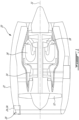
- Fig. 1 illustrates a gas turbine engine 10 of a type preferably provided for use in subsonic flight, generally comprising in serial flow communication an inlet 20, a fan 12 through which ambient air is propelled, a compressor section 14 for pressurizing the air, a combustor 16 in which the compressed air is mixed with fuel and ignited for generating an annular stream of hot combustion gases, and a turbine section 18 for extracting energy from the combustion gases, with rotary components rotating around a main axis 11.
- the gas turbine engine 10 is housed in a nacelle 22, which has an aerodynamically shaped external surface.
- the nacelle 22 forms an enclosure which is distinct from the passenger compartment of the aircraft, and more specifically, the nacelle 22 is separated from the passenger compartment by a portion of a wing of the aircraft (not shown).
- Gas turbine engines 10 typically have a main gas path extending through the compressor section 14, combustor 16 and turbine section 18.
- Turbofan engines have a bypass path formed around the core engine, within the nacelle 22.
- the inlet fluidly communicates with the main gas path, and in this case, it also communicates with the bypass path.
- the shape of the nacelle 22 depends on the type of engine and is typically selected in a manner to accommodate the specifics of the engine.
- FIG. 2A An inlet portion 20 of an example nacelle 22 is shown enlarged in Fig. 2A .
- the inlet portion 20 has an inlet edge 102 which, during flight, separates a portion of the flow which is directed into the engine 10, a sub-portion of which will flow along an internal duct wall 104 of the engine 10, from a portion of the flow which is directed around the nacelle 22, a sub-portion of which will flow along an external skin 106 of the nacelle 22.
- the inlet edge is rounded.
- the example inlet portion 20 is provided with a heater internal to the rounded portion 108.
- the heater can be a heating air conduit 110 having a plurality of apertures dissipating hotter air bled from the compressor, for instance, or any suitable heater.
- the heater can be used to heat water, in solid or liquid phase, which comes into contact with the inlet portion 20, to avoid it forming and accumulating a layer of ice, which could eventually dislodge and represent a potential FOD.
- the power directed to the heater can be modulated as a function of the amount of power expected to be required to achieve this purpose, for instance.
- the heater has a limited range, and even if, for a given power, it can avoid ice accumulation within its range, liquid water circulating along the surface can eventually exit its range and form an ice accumulation downstream of its range.
- the range of the heater can be extended, to a certain extent, by supplying additional power (hotter water will travel further before freezing, especially if it runs along a warmer surface), but this is done at the cost of the additional power, which is typically undesired.
- some embodiments may have practical limitations to the amount of extension of heater range achievable by added power.
- Fig. 2B presents an example embodiment where a step 112A is provided in the surface 115 along which the liquid water circulates, in a manner that as the liquid water droplets 113 reach the edge of the step 112A, its velocity, entrained by the air velocity and viscosity, entrains its separation, and ejection, from the surface 115, after which it can remain entrained in the air flow rather than freezing and accumulating onto a cooler portion of the surface, to eventually detach and cause FOD.
- small droplets of water even when solidified into small ice fragments, can have insufficient mass to cause any damage to the engine, by contrast with larger ice accumulations.
- the step 112A is formed in the duct wall 104 of the gas turbine engine 10, in the vicinity of the inlet edge 102.
- the step 112A can be said to form a discontinuity in the surface 115, or to more specifically delimit a recessed (or second) portion 114 of the surface 115 from a non-recessed (or first) portion 116 of the surface 115.
- the recessed portion 114 of the surface 115 is offset, at the step 112A, from the non-recessed portion 116 of the surface 115 by a distance equivalent to the "height" of the step 112A.
- the recessed portion 114 is recessed relative to the air flow.
- the step 112A faces downstream relative to the movement of the water along the surface, in the sense that if an imaginary Lilliputian person would walk and go up the step, he would be walking against the wind flow, whereas if he would walk and go down the step, he would have the wind in its back. Otherwise said, the recessed portion 114 extends from the step 112A both away from the step 112A and the rounded portion 102, whereas the non-recessed portion 116 extends between the rounded portion 102 and the step 112A.
- the height of the step 112A can vary greatly depending on the size of the engine and the specifics of the embodiment. However, for the purpose of providing an order of magnitude, it can be said here that the height of the step 112A can be expected to be between 0.254 mm (0.010") and 5.08 mm (0.200") in most practical applications. Greater heights may represent a flow distortion judged as being too large, while not providing sufficient compensating advantages, whereas a height smaller than 0.254 mm (0.010") may not be sufficient to cause ejection of the water droplets 113. The exact height for a specific application can be determined based on simulation or testing, for instance. Similarly, the sharpness of the step, i.e.
- the dimension of the fillet radius of the edge of the step can vary greatly from one embodiment to another and can be chosen in view of optimizing the efficiency of a specific embodiment.
- the ratio of the fillet radius to the height of the step can be between 0 and 1, and the fillet radius can thus be less than 5.08 mm (0.200"), for example.
- the step 112A has a riser in the form of a riser portion of the surface, which extends normal to the recessed portion 114 of the surface 115, along a distance corresponding to the height of the step 112A.
- the riser faces downstream relative to the movement of the water droplets 113, or in this specific embodiment, rearwardly relative to the orientation of thrust of the turbofan engine.
- Providing a step 112A along the bypass duct wall of the turbofan engine, as opposed to along the nacelle skin, can be particularly useful in avoiding ice accumulation which would be likely to otherwise form a potential source of FOD.
- ice accumulating on the nacelle skin 106 will typically not represent a potential source of FOD during flight, however it can still be undesired for other reasons.
- the flow dynamics during takeoff are very different than during flight, hence if ice has accumulated on a nacelle skin 106 on a previous flight and remains in the vicinity of the inlet, a sufficient velocity of air may be drawn forwardly along the skin, towards the inlet, during the next takeoff, causing detachment of the ice accumulation and a FOD.
- a backward facing step 112B on the external skin 106 of the nacelle 22 in addition to, or perhaps even instead of, a step 112A on the internal duct wall 104.
- This backward facing step 112B on the external skin 106 can be used to eject water running along the surface during flight, prevent the ejected water from freezing and forming an ice accumulation during flight, and thus prevent eventual aspiration of such an ice accumulation by a reverse flow occurring during takeoff, for instance.
- Fig. 2C shows an example of a nacelle inlet 20 having a step 112B formed on the external skin 106 on the nacelle 22.
- the inlet 20 of the turbofan gas turbine engine extends annularly around the engine's main axis 11, and therefore the inlet edge 102, skin 106, and duct wall 104 can be axisymmetric around the main axis 11.
- the step extends around the entire circumference of the inlet 20.
- the duct wall 104 is an outer bypass duct wall of the turbofan gas turbine engine.
- the inlet edge 102 forms part of a D-duct 108 connected to a remainder of the nacelle 22, or bypass duct, as known in the art, and the heating conduit 110 can extend circumferentially within the D-duct 108, for instance.
- the step is formed by, the junction between the D-duct 108 and adjacent sections of the nacelle 22.
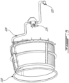
- the heating conduit 110 can have a plurality of apertures forming heating air outlets, and be connected to a compressor to receive bleed air therefrom. An example of a possible arrangement is shown in Fig.
- annular heating conduit 210 is shown to be connected, via a thermally insulated pipe segment 220, to an engine bleed port 222, and such an arrangement can have a pressure regulating and shut-off valve (PRSOV) 224 associated with the thermally insulated pipe segment 220, for instance.
- PRSOV pressure regulating and shut-off valve
- turbofan engines it is common for turbofan engines to have outer bypass ducts integrating acoustic panels 118 in a manner to impede sound transmission from the core engine to the passengers.
- the step 112A can be located between the inlet edge 102, and the acoustic panel 118, for instance.
Landscapes
- Engineering & Computer Science (AREA)
- Chemical & Material Sciences (AREA)
- Combustion & Propulsion (AREA)
- Aviation & Aerospace Engineering (AREA)
- Mechanical Engineering (AREA)
- General Engineering & Computer Science (AREA)
- Structures Of Non-Positive Displacement Pumps (AREA)
Claims (15)
- Turbofan-Triebwerksgondel (22), die einen Einlass (20) umfasst, der dazu konfiguriert ist, mit einem Hauptgaspfad eines Turbofan-Triebwerkskerns fluidverbunden zu sein, wobei:der Einlass (20) eine Einlasskante (102), die eine äußere Haut (106) mit einer inneren Kanalwand (104) verbindet, und eine Stufe (112A) aufweist, die in einer Fläche (115) von mindestens einem von der äußeren Haut (106) und der Kanalwand (104) gebildet ist, wobei die Stufe (112A) einen ersten Abschnitt (116) der Fläche (115) von einem zweiten Abschnitt (114) der Fläche (115) abgrenzt, wobei der zweite Abschnitt (114) der Fläche (115) relativ zu dem ersten Abschnitt (116) der Fläche (115) um die Höhe der Stufe (112A) vertieft ist;der zweite Abschnitt (114) der Fläche (115) sich sowohl von der Stufe (112A) als auch von der Einlasskante (102) weg erstreckt;der erste Abschnitt (116) der Fläche (115) sich zwischen der Einlasskante (102) und der Stufe (112A) erstreckt;die Stufe (112A) sich um einen gesamten Umfang des Einlasses (20) herum erstreckt; dadurch gekennzeichnet, dass:die Stufe durch eine Verbindungsstelle zwischen einem D-Kanal (108) und benachbarten Abschnitten der Gondel (22) gebildet ist; unddie Turbofan-Triebwerksgondel (22) ferner eine Heizvorrichtung innerhalb des D-Kanals (108) umfasst, wobei die Heizvorrichtung dazu konfiguriert ist, Wasser, in fester oder flüssiger Phase, zu erhitzen, das mit dem Einlass (20) in Kontakt kommt.
- Turbofan-Triebwerksgondel (22) nach Anspruch 1, wobei die Höhe der Stufe (112A) normal zu der Fläche (115) gemessen zwischen 0,254 mm (0,010 Zoll) und 5,08 mm (0,200 Zoll) beträgt.
- Turbofan-Triebwerksgondel (22) nach Anspruch 1 oder 2, wobei die Stufe (112A) eine Setzstufe aufweist.
- Turbofan-Triebwerksgondel (22) nach einem der vorhergehenden Ansprüche, wobei die Kanalwand (104) eine äußere Umgehungskanalwand ist.
- Turbofan-Triebwerksgondel (22) nach einem der vorhergehenden Ansprüche, wobei der D-Kanal (108) die Haut (106) und die Kanalwand (104) verbindet.
- Turbofan-Triebwerksgondel (22) nach Anspruch 5, wobei die Stufe (112A) an einer Verbindungsstelle zwischen dem D-Kanal (108) und der Kanalwand (104) gebildet ist.
- Turbofan-Triebwerksgondel (22) nach Anspruch 4 oder 5, wobei die Heizvorrichtung eine Heizluftleitung (110) ist, die innerhalb des D-Kanals (108) bereitgestellt ist, wobei die Heizluftleitung (110) eine Vielzahl von Heizluftauslässen aufweist und mit einer Kompressorzapfluftquelle verbunden ist.
- Turbofan-Triebwerksgondel (22) nach einem der vorhergehenden Ansprüche, wobei die innere Kanalwand (104) eine Akustikplatte (118) aufweist, wobei die Stufe (112A) sich zwischen der Einlasskante (102) und der Akustikplatte (118) befindet.
- Turbofan-Triebwerksgondel (22) nach einem der vorhergehenden Ansprüche, wobei die Stufe (112A) in der Kanalwand (104) gebildet ist.
- Turbofan-Triebwerksgondel (22) nach einem der vorhergehenden Ansprüche, ferner umfassend eine andere Stufe (112B), die in der Haut (106) gebildet ist, wobei die andere Stufe (112B) einen vertieften Abschnitt der Haut (106) begrenzt, wobei der vertiefte Abschnitt (114) der Haut (106) sich sowohl von der anderen Stufe (112A) als auch von der Einlasskante (102) weg erstreckt.
- Turbofan-Triebwerksgondel (22) nach einem der vorhergehenden Ansprüche, wobei die Einlasskante (102), die Haut (106) und der Kanal ringförmig (104) sind.
- Turbofan-Triebwerksgondel (22) nach einem der vorhergehenden Ansprüche, wobei die Stufe (112B) nach hinten weist.
- Verfahren zum Betreiben eines Turbofan-Triebwerks (10), wobei das Verfahren umfasst, dass ein Luftstrom entlang einer Fläche (115) eines Einlassabschnitts (20) des Turbofan-Triebwerks (10) zirkuliert, wobei der Luftstrom Wassertropfen (113) entlang der Fläche (115) zieht, bis die Wassertropfen (113) eine Kante einer Stufe (112A) erreichen, die zu einem vertieften Abschnitt (114) der Fläche (115) führt, wobei der Luftstrom die Wassertropfen (113) an der Kante der Stufe (112A) von der Fläche (115) trennt, wobei die Stufe (112A) sich um einen gesamten Umfang des Einlasses (20) herum erstreckt und die Stufe durch eine Verbindungsstelle zwischen einem D-Kanal (108) und benachbarten Abschnitten einer Gondel (22) gebildet ist, wobei das Verfahren ferner Verwenden einer Heizvorrichtung in dem D-Kanal (108) umfasst, um Wasser, in fester oder flüssiger Phase, zu erhitzen, das mit dem Einlassabschnitt (20) in Kontakt kommt.
- Verfahren nach Anspruch 13, wobei das Verfahren ferner umfasst, das Wasser in festem Zustand einem Erhitzen zu unterziehen, und dadurch das Wasser in festem Zustand in die Wassertropfen (113) umzuwandeln.
- Verfahren nach Anspruch 13 oder 14, ferner umfassend Leiten der abgelösten Wassertropfen (113) in einen Hauptgaspfad eines Turbofan-Triebwerkskerns oder einen Umgehungskanal.
Applications Claiming Priority (1)
| Application Number | Priority Date | Filing Date | Title |
|---|---|---|---|
| US16/699,001 US20210163141A1 (en) | 2019-11-28 | 2019-11-28 | Gas turbine engine, nacelle thereof, and associated method of operating a gas turbine engine |
Publications (2)
| Publication Number | Publication Date |
|---|---|
| EP3828078A1 EP3828078A1 (de) | 2021-06-02 |
| EP3828078B1 true EP3828078B1 (de) | 2024-07-31 |
Family
ID=73646086
Family Applications (1)
| Application Number | Title | Priority Date | Filing Date |
|---|---|---|---|
| EP20210487.3A Active EP3828078B1 (de) | 2019-11-28 | 2020-11-27 | Gasturbinentriebwerk, dessen triebwerksgondel und verfahren zum betrieb eines gasturbinentriebwerks |
Country Status (3)
| Country | Link |
|---|---|
| US (2) | US20210163141A1 (de) |
| EP (1) | EP3828078B1 (de) |
| CA (1) | CA3099300A1 (de) |
Families Citing this family (3)
| Publication number | Priority date | Publication date | Assignee | Title |
|---|---|---|---|---|
| FR3096662B1 (fr) * | 2019-05-27 | 2022-08-12 | Safran Nacelles | Lèvre d’entrée d’air de nacelle de turbomachine comprenant un dispositif acoustique et procédé de fabrication d’une telle lèvre |
| US11840933B2 (en) * | 2019-12-13 | 2023-12-12 | Rtx Corporation | LiDAR based FOD detection for gas-turbine engines |
| FR3155259B1 (fr) * | 2023-11-10 | 2025-11-07 | Safran Aircraft Engines | Systeme antigivrage d’une veine d’air pour un compresseur pour une turbomachine d’aeronef et procede antigivrage d’une veine d’air pour un compresseur pour une turbomachine d’aeronef |
Family Cites Families (21)
| Publication number | Priority date | Publication date | Assignee | Title |
|---|---|---|---|---|
| US3933327A (en) | 1974-08-30 | 1976-01-20 | Rohr Industries, Inc. | Aircraft anti-icing plenum |
| AU581684B2 (en) | 1984-10-08 | 1989-03-02 | Short Brothers Plc | Duct for hot air |
| US4688745A (en) * | 1986-01-24 | 1987-08-25 | Rohr Industries, Inc. | Swirl anti-ice system |
| US4738416A (en) | 1986-09-26 | 1988-04-19 | Quiet Nacelle Corporation | Nacelle anti-icing system |
| US5088277A (en) * | 1988-10-03 | 1992-02-18 | General Electric Company | Aircraft engine inlet cowl anti-icing system |
| US5694763A (en) | 1990-04-11 | 1997-12-09 | United Technologies Corporation | Low observable engine inlet system |
| US5322246A (en) * | 1991-08-12 | 1994-06-21 | Mcdonnell Douglas Corporation | Ice prevention device for airfoils |
| DE59206416D1 (de) | 1991-12-05 | 1996-07-04 | Aginfor Ag | Verdrängermaschine nach dem Spiralprinzip |
| US5257498A (en) * | 1992-04-23 | 1993-11-02 | United Technologies Corporation | Efficient anti-ice exhaust vent |
| FR2771776B1 (fr) * | 1997-12-02 | 2000-01-28 | Aerospatiale | Dispositif d'evacuation d'air chaud pour capot d'entree d'air de moteur a reaction, a circuit de degivrage |
| FR2820716B1 (fr) * | 2001-02-15 | 2003-05-30 | Eads Airbus Sa | Procede de degivrage par circulation forcee d'un fluide, d'un capot d'entree d'air de moteur a reaction et dispositif pour sa mise en oeuvre |
| US6561760B2 (en) * | 2001-08-17 | 2003-05-13 | General Electric Company | Booster compressor deicer |
| US7328623B2 (en) * | 2006-03-20 | 2008-02-12 | General Electric Company | Temperature and/or pressure sensor assembly |
| US20160052621A1 (en) * | 2009-07-10 | 2016-02-25 | Peter Ireland | Energy efficiency improvements for turbomachinery |
| US20140263837A1 (en) * | 2013-03-12 | 2014-09-18 | Spirit Aerosystems, Inc. | Nacelle inlet thermal anti-ice spray duct |
| EP2821597B1 (de) * | 2013-07-05 | 2016-02-10 | Techspace Aero S.A. | Trennkante mit Blech zur Bildung einer Fläche zur Strömungsleitung und eines Enteisungskanals |
| GB2518232A (en) | 2013-09-17 | 2015-03-18 | Airbus Operations Ltd | Ice accretion prevention |
| US9938855B2 (en) * | 2014-01-31 | 2018-04-10 | Pratt & Whitney Canada Corp. | Cooling system and method for supplying a cooling gas flow |
| FR3023538B1 (fr) | 2014-07-11 | 2016-07-15 | Aircelle Sa | Levre avant de nacelle de turboreacteur comportant des percages d’air chaud en amont de panneaux acoustiques |
| BE1023354B1 (fr) * | 2015-08-13 | 2017-02-13 | Safran Aero Boosters S.A. | Bec de separation degivrant de compresseur de turbomachine axiale |
| US11085372B2 (en) * | 2018-07-18 | 2021-08-10 | The Boeing Company | Anti-ice system exhaust air disruptor |
-
2019
- 2019-11-28 US US16/699,001 patent/US20210163141A1/en not_active Abandoned
-
2020
- 2020-01-28 US US16/774,778 patent/US11807379B2/en active Active
- 2020-11-13 CA CA3099300A patent/CA3099300A1/en active Pending
- 2020-11-27 EP EP20210487.3A patent/EP3828078B1/de active Active
Also Published As
| Publication number | Publication date |
|---|---|
| US11807379B2 (en) | 2023-11-07 |
| EP3828078A1 (de) | 2021-06-02 |
| US20210163146A1 (en) | 2021-06-03 |
| US20210163141A1 (en) | 2021-06-03 |
| CA3099300A1 (en) | 2021-05-28 |
Similar Documents
| Publication | Publication Date | Title |
|---|---|---|
| US9429072B2 (en) | Return fluid air cooler system for turbine cooling with optional power extraction | |
| US6725645B1 (en) | Turbofan engine internal anti-ice device | |
| US10654579B2 (en) | Cooled cooling air system for a gas turbine | |
| US6561760B2 (en) | Booster compressor deicer | |
| EP2383441B1 (de) | Gasturbinenmotor | |
| EP0459816B1 (de) | Gasturbinenbetriebenes Klimakontroll- und Grenzschichtabsaugsystem für Flugzeuge | |
| EP3171009B1 (de) | Kompressionshaube für düsentriebwerkauslass | |
| EP2604807A2 (de) | System und Verfahren für aktive Einstellung des Spiels | |
| EP3828078B1 (de) | Gasturbinentriebwerk, dessen triebwerksgondel und verfahren zum betrieb eines gasturbinentriebwerks | |
| EP0459815A1 (de) | Luftwiderstandsverminderung bei einem Mantelkanal für ein Bläsertriebwerk | |
| WO2014018126A2 (en) | High pressure muffling devices | |
| EP3321490B1 (de) | Turbogeneratorbasiertes zapfluftsystem | |
| US11674438B1 (en) | Thermal management system | |
| US11085312B2 (en) | Aircraft incorporating a thrust recovery system using cabin air | |
| EP3590846A1 (de) | Motorgehäuse lufteinlassbereich | |
| CA3105434A1 (en) | Turbofan engine, nacelle thereof, and associated method of operation | |
| US12110810B2 (en) | Gas turbine engine bleed air flow control | |
| US20250129747A1 (en) | Nacelle for a gas turbine engine |
Legal Events
| Date | Code | Title | Description |
|---|---|---|---|
| PUAI | Public reference made under article 153(3) epc to a published international application that has entered the european phase |
Free format text: ORIGINAL CODE: 0009012 |
|
| STAA | Information on the status of an ep patent application or granted ep patent |
Free format text: STATUS: THE APPLICATION HAS BEEN PUBLISHED |
|
| AK | Designated contracting states |
Kind code of ref document: A1 Designated state(s): AL AT BE BG CH CY CZ DE DK EE ES FI FR GB GR HR HU IE IS IT LI LT LU LV MC MK MT NL NO PL PT RO RS SE SI SK SM TR |
|
| STAA | Information on the status of an ep patent application or granted ep patent |
Free format text: STATUS: REQUEST FOR EXAMINATION WAS MADE |
|
| 17P | Request for examination filed |
Effective date: 20211202 |
|
| RBV | Designated contracting states (corrected) |
Designated state(s): AL AT BE BG CH CY CZ DE DK EE ES FI FR GB GR HR HU IE IS IT LI LT LU LV MC MK MT NL NO PL PT RO RS SE SI SK SM TR |
|
| STAA | Information on the status of an ep patent application or granted ep patent |
Free format text: STATUS: EXAMINATION IS IN PROGRESS |
|
| 17Q | First examination report despatched |
Effective date: 20220930 |
|
| GRAP | Despatch of communication of intention to grant a patent |
Free format text: ORIGINAL CODE: EPIDOSNIGR1 |
|
| STAA | Information on the status of an ep patent application or granted ep patent |
Free format text: STATUS: GRANT OF PATENT IS INTENDED |
|
| INTG | Intention to grant announced |
Effective date: 20240222 |
|
| GRAS | Grant fee paid |
Free format text: ORIGINAL CODE: EPIDOSNIGR3 |
|
| GRAA | (expected) grant |
Free format text: ORIGINAL CODE: 0009210 |
|
| STAA | Information on the status of an ep patent application or granted ep patent |
Free format text: STATUS: THE PATENT HAS BEEN GRANTED |
|
| AK | Designated contracting states |
Kind code of ref document: B1 Designated state(s): AL AT BE BG CH CY CZ DE DK EE ES FI FR GB GR HR HU IE IS IT LI LT LU LV MC MK MT NL NO PL PT RO RS SE SI SK SM TR |
|
| REG | Reference to a national code |
Ref country code: CH Ref legal event code: EP Ref country code: GB Ref legal event code: FG4D |
|
| REG | Reference to a national code |
Ref country code: DE Ref legal event code: R096 Ref document number: 602020034789 Country of ref document: DE |
|
| REG | Reference to a national code |
Ref country code: IE Ref legal event code: FG4D |
|
| REG | Reference to a national code |
Ref country code: LT Ref legal event code: MG9D |
|
| REG | Reference to a national code |
Ref country code: NL Ref legal event code: MP Effective date: 20240731 |
|
| PG25 | Lapsed in a contracting state [announced via postgrant information from national office to epo] |
Ref country code: PT Free format text: LAPSE BECAUSE OF FAILURE TO SUBMIT A TRANSLATION OF THE DESCRIPTION OR TO PAY THE FEE WITHIN THE PRESCRIBED TIME-LIMIT Effective date: 20241202 |
|
| REG | Reference to a national code |
Ref country code: AT Ref legal event code: MK05 Ref document number: 1708248 Country of ref document: AT Kind code of ref document: T Effective date: 20240731 |
|
| PG25 | Lapsed in a contracting state [announced via postgrant information from national office to epo] |
Ref country code: PT Free format text: LAPSE BECAUSE OF FAILURE TO SUBMIT A TRANSLATION OF THE DESCRIPTION OR TO PAY THE FEE WITHIN THE PRESCRIBED TIME-LIMIT Effective date: 20241202 |
|
| PG25 | Lapsed in a contracting state [announced via postgrant information from national office to epo] |
Ref country code: NO Free format text: LAPSE BECAUSE OF FAILURE TO SUBMIT A TRANSLATION OF THE DESCRIPTION OR TO PAY THE FEE WITHIN THE PRESCRIBED TIME-LIMIT Effective date: 20241031 |
|
| PG25 | Lapsed in a contracting state [announced via postgrant information from national office to epo] |
Ref country code: NL Free format text: LAPSE BECAUSE OF FAILURE TO SUBMIT A TRANSLATION OF THE DESCRIPTION OR TO PAY THE FEE WITHIN THE PRESCRIBED TIME-LIMIT Effective date: 20240731 Ref country code: GR Free format text: LAPSE BECAUSE OF FAILURE TO SUBMIT A TRANSLATION OF THE DESCRIPTION OR TO PAY THE FEE WITHIN THE PRESCRIBED TIME-LIMIT Effective date: 20241101 Ref country code: PL Free format text: LAPSE BECAUSE OF FAILURE TO SUBMIT A TRANSLATION OF THE DESCRIPTION OR TO PAY THE FEE WITHIN THE PRESCRIBED TIME-LIMIT Effective date: 20240731 Ref country code: FI Free format text: LAPSE BECAUSE OF FAILURE TO SUBMIT A TRANSLATION OF THE DESCRIPTION OR TO PAY THE FEE WITHIN THE PRESCRIBED TIME-LIMIT Effective date: 20240731 |
|
| PG25 | Lapsed in a contracting state [announced via postgrant information from national office to epo] |
Ref country code: BG Free format text: LAPSE BECAUSE OF FAILURE TO SUBMIT A TRANSLATION OF THE DESCRIPTION OR TO PAY THE FEE WITHIN THE PRESCRIBED TIME-LIMIT Effective date: 20240731 |
|
| PG25 | Lapsed in a contracting state [announced via postgrant information from national office to epo] |
Ref country code: LV Free format text: LAPSE BECAUSE OF FAILURE TO SUBMIT A TRANSLATION OF THE DESCRIPTION OR TO PAY THE FEE WITHIN THE PRESCRIBED TIME-LIMIT Effective date: 20240731 |
|
| PG25 | Lapsed in a contracting state [announced via postgrant information from national office to epo] |
Ref country code: AT Free format text: LAPSE BECAUSE OF FAILURE TO SUBMIT A TRANSLATION OF THE DESCRIPTION OR TO PAY THE FEE WITHIN THE PRESCRIBED TIME-LIMIT Effective date: 20240731 Ref country code: IS Free format text: LAPSE BECAUSE OF FAILURE TO SUBMIT A TRANSLATION OF THE DESCRIPTION OR TO PAY THE FEE WITHIN THE PRESCRIBED TIME-LIMIT Effective date: 20241130 |
|
| PG25 | Lapsed in a contracting state [announced via postgrant information from national office to epo] |
Ref country code: HR Free format text: LAPSE BECAUSE OF FAILURE TO SUBMIT A TRANSLATION OF THE DESCRIPTION OR TO PAY THE FEE WITHIN THE PRESCRIBED TIME-LIMIT Effective date: 20240731 |
|
| PG25 | Lapsed in a contracting state [announced via postgrant information from national office to epo] |
Ref country code: RS Free format text: LAPSE BECAUSE OF FAILURE TO SUBMIT A TRANSLATION OF THE DESCRIPTION OR TO PAY THE FEE WITHIN THE PRESCRIBED TIME-LIMIT Effective date: 20241031 Ref country code: ES Free format text: LAPSE BECAUSE OF FAILURE TO SUBMIT A TRANSLATION OF THE DESCRIPTION OR TO PAY THE FEE WITHIN THE PRESCRIBED TIME-LIMIT Effective date: 20240731 |
|
| PG25 | Lapsed in a contracting state [announced via postgrant information from national office to epo] |
Ref country code: RS Free format text: LAPSE BECAUSE OF FAILURE TO SUBMIT A TRANSLATION OF THE DESCRIPTION OR TO PAY THE FEE WITHIN THE PRESCRIBED TIME-LIMIT Effective date: 20241031 Ref country code: PL Free format text: LAPSE BECAUSE OF FAILURE TO SUBMIT A TRANSLATION OF THE DESCRIPTION OR TO PAY THE FEE WITHIN THE PRESCRIBED TIME-LIMIT Effective date: 20240731 Ref country code: NO Free format text: LAPSE BECAUSE OF FAILURE TO SUBMIT A TRANSLATION OF THE DESCRIPTION OR TO PAY THE FEE WITHIN THE PRESCRIBED TIME-LIMIT Effective date: 20241031 Ref country code: NL Free format text: LAPSE BECAUSE OF FAILURE TO SUBMIT A TRANSLATION OF THE DESCRIPTION OR TO PAY THE FEE WITHIN THE PRESCRIBED TIME-LIMIT Effective date: 20240731 Ref country code: LV Free format text: LAPSE BECAUSE OF FAILURE TO SUBMIT A TRANSLATION OF THE DESCRIPTION OR TO PAY THE FEE WITHIN THE PRESCRIBED TIME-LIMIT Effective date: 20240731 Ref country code: IS Free format text: LAPSE BECAUSE OF FAILURE TO SUBMIT A TRANSLATION OF THE DESCRIPTION OR TO PAY THE FEE WITHIN THE PRESCRIBED TIME-LIMIT Effective date: 20241130 Ref country code: HR Free format text: LAPSE BECAUSE OF FAILURE TO SUBMIT A TRANSLATION OF THE DESCRIPTION OR TO PAY THE FEE WITHIN THE PRESCRIBED TIME-LIMIT Effective date: 20240731 Ref country code: GR Free format text: LAPSE BECAUSE OF FAILURE TO SUBMIT A TRANSLATION OF THE DESCRIPTION OR TO PAY THE FEE WITHIN THE PRESCRIBED TIME-LIMIT Effective date: 20241101 Ref country code: FI Free format text: LAPSE BECAUSE OF FAILURE TO SUBMIT A TRANSLATION OF THE DESCRIPTION OR TO PAY THE FEE WITHIN THE PRESCRIBED TIME-LIMIT Effective date: 20240731 Ref country code: ES Free format text: LAPSE BECAUSE OF FAILURE TO SUBMIT A TRANSLATION OF THE DESCRIPTION OR TO PAY THE FEE WITHIN THE PRESCRIBED TIME-LIMIT Effective date: 20240731 Ref country code: BG Free format text: LAPSE BECAUSE OF FAILURE TO SUBMIT A TRANSLATION OF THE DESCRIPTION OR TO PAY THE FEE WITHIN THE PRESCRIBED TIME-LIMIT Effective date: 20240731 Ref country code: AT Free format text: LAPSE BECAUSE OF FAILURE TO SUBMIT A TRANSLATION OF THE DESCRIPTION OR TO PAY THE FEE WITHIN THE PRESCRIBED TIME-LIMIT Effective date: 20240731 |
|
| PG25 | Lapsed in a contracting state [announced via postgrant information from national office to epo] |
Ref country code: RO Free format text: LAPSE BECAUSE OF FAILURE TO SUBMIT A TRANSLATION OF THE DESCRIPTION OR TO PAY THE FEE WITHIN THE PRESCRIBED TIME-LIMIT Effective date: 20240731 Ref country code: SM Free format text: LAPSE BECAUSE OF FAILURE TO SUBMIT A TRANSLATION OF THE DESCRIPTION OR TO PAY THE FEE WITHIN THE PRESCRIBED TIME-LIMIT Effective date: 20240731 Ref country code: DK Free format text: LAPSE BECAUSE OF FAILURE TO SUBMIT A TRANSLATION OF THE DESCRIPTION OR TO PAY THE FEE WITHIN THE PRESCRIBED TIME-LIMIT Effective date: 20240731 |
|
| PG25 | Lapsed in a contracting state [announced via postgrant information from national office to epo] |
Ref country code: EE Free format text: LAPSE BECAUSE OF FAILURE TO SUBMIT A TRANSLATION OF THE DESCRIPTION OR TO PAY THE FEE WITHIN THE PRESCRIBED TIME-LIMIT Effective date: 20240731 |
|
| PG25 | Lapsed in a contracting state [announced via postgrant information from national office to epo] |
Ref country code: CZ Free format text: LAPSE BECAUSE OF FAILURE TO SUBMIT A TRANSLATION OF THE DESCRIPTION OR TO PAY THE FEE WITHIN THE PRESCRIBED TIME-LIMIT Effective date: 20240731 |
|
| PG25 | Lapsed in a contracting state [announced via postgrant information from national office to epo] |
Ref country code: IT Free format text: LAPSE BECAUSE OF FAILURE TO SUBMIT A TRANSLATION OF THE DESCRIPTION OR TO PAY THE FEE WITHIN THE PRESCRIBED TIME-LIMIT Effective date: 20240731 Ref country code: SK Free format text: LAPSE BECAUSE OF FAILURE TO SUBMIT A TRANSLATION OF THE DESCRIPTION OR TO PAY THE FEE WITHIN THE PRESCRIBED TIME-LIMIT Effective date: 20240731 |
|
| REG | Reference to a national code |
Ref country code: DE Ref legal event code: R097 Ref document number: 602020034789 Country of ref document: DE |
|
| PLBE | No opposition filed within time limit |
Free format text: ORIGINAL CODE: 0009261 |
|
| STAA | Information on the status of an ep patent application or granted ep patent |
Free format text: STATUS: NO OPPOSITION FILED WITHIN TIME LIMIT |
|
| REG | Reference to a national code |
Ref country code: CH Ref legal event code: PL |
|
| PG25 | Lapsed in a contracting state [announced via postgrant information from national office to epo] |
Ref country code: MC Free format text: LAPSE BECAUSE OF FAILURE TO SUBMIT A TRANSLATION OF THE DESCRIPTION OR TO PAY THE FEE WITHIN THE PRESCRIBED TIME-LIMIT Effective date: 20240731 |
|
| 26N | No opposition filed |
Effective date: 20250501 |
|
| PG25 | Lapsed in a contracting state [announced via postgrant information from national office to epo] |
Ref country code: LU Free format text: LAPSE BECAUSE OF NON-PAYMENT OF DUE FEES Effective date: 20241127 |
|
| REG | Reference to a national code |
Ref country code: CH Ref legal event code: PL |
|
| PG25 | Lapsed in a contracting state [announced via postgrant information from national office to epo] |
Ref country code: CH Free format text: LAPSE BECAUSE OF NON-PAYMENT OF DUE FEES Effective date: 20241130 |
|
| REG | Reference to a national code |
Ref country code: BE Ref legal event code: MM Effective date: 20241130 |
|
| PG25 | Lapsed in a contracting state [announced via postgrant information from national office to epo] |
Ref country code: SE Free format text: LAPSE BECAUSE OF FAILURE TO SUBMIT A TRANSLATION OF THE DESCRIPTION OR TO PAY THE FEE WITHIN THE PRESCRIBED TIME-LIMIT Effective date: 20240731 |
|
| PG25 | Lapsed in a contracting state [announced via postgrant information from national office to epo] |
Ref country code: BE Free format text: LAPSE BECAUSE OF NON-PAYMENT OF DUE FEES Effective date: 20241130 |
|
| PG25 | Lapsed in a contracting state [announced via postgrant information from national office to epo] |
Ref country code: IE Free format text: LAPSE BECAUSE OF NON-PAYMENT OF DUE FEES Effective date: 20241127 |
|
| PGFP | Annual fee paid to national office [announced via postgrant information from national office to epo] |
Ref country code: DE Payment date: 20251022 Year of fee payment: 6 |
|
| PGFP | Annual fee paid to national office [announced via postgrant information from national office to epo] |
Ref country code: GB Payment date: 20251022 Year of fee payment: 6 |
|
| PGFP | Annual fee paid to national office [announced via postgrant information from national office to epo] |
Ref country code: FR Payment date: 20251022 Year of fee payment: 6 |
|
| PG25 | Lapsed in a contracting state [announced via postgrant information from national office to epo] |
Ref country code: HU Free format text: LAPSE BECAUSE OF FAILURE TO SUBMIT A TRANSLATION OF THE DESCRIPTION OR TO PAY THE FEE WITHIN THE PRESCRIBED TIME-LIMIT; INVALID AB INITIO Effective date: 20201127 |
|
| PG25 | Lapsed in a contracting state [announced via postgrant information from national office to epo] |
Ref country code: CY Free format text: LAPSE BECAUSE OF FAILURE TO SUBMIT A TRANSLATION OF THE DESCRIPTION OR TO PAY THE FEE WITHIN THE PRESCRIBED TIME-LIMIT; INVALID AB INITIO Effective date: 20201127 |