EP3828399B1 - Échangeur air/carburant interne - Google Patents
Échangeur air/carburant interne Download PDFInfo
- Publication number
- EP3828399B1 EP3828399B1 EP20208050.3A EP20208050A EP3828399B1 EP 3828399 B1 EP3828399 B1 EP 3828399B1 EP 20208050 A EP20208050 A EP 20208050A EP 3828399 B1 EP3828399 B1 EP 3828399B1
- Authority
- EP
- European Patent Office
- Prior art keywords
- fuel
- heat exchanger
- engine case
- recited
- air
- Prior art date
- Legal status (The legal status is an assumption and is not a legal conclusion. Google has not performed a legal analysis and makes no representation as to the accuracy of the status listed.)
- Active
Links
Images


Classifications
-
- F—MECHANICAL ENGINEERING; LIGHTING; HEATING; WEAPONS; BLASTING
- F02—COMBUSTION ENGINES; HOT-GAS OR COMBUSTION-PRODUCT ENGINE PLANTS
- F02C—GAS-TURBINE PLANTS; AIR INTAKES FOR JET-PROPULSION PLANTS; CONTROLLING FUEL SUPPLY IN AIR-BREATHING JET-PROPULSION PLANTS
- F02C7/00—Features, components parts, details or accessories, not provided for in, or of interest apart form groups F02C1/00 - F02C6/00; Air intakes for jet-propulsion plants
- F02C7/12—Cooling of plants
- F02C7/14—Cooling of plants of fluids in the plant, e.g. lubricant or fuel
- F02C7/141—Cooling of plants of fluids in the plant, e.g. lubricant or fuel of working fluid
-
- F—MECHANICAL ENGINEERING; LIGHTING; HEATING; WEAPONS; BLASTING
- F02—COMBUSTION ENGINES; HOT-GAS OR COMBUSTION-PRODUCT ENGINE PLANTS
- F02C—GAS-TURBINE PLANTS; AIR INTAKES FOR JET-PROPULSION PLANTS; CONTROLLING FUEL SUPPLY IN AIR-BREATHING JET-PROPULSION PLANTS
- F02C7/00—Features, components parts, details or accessories, not provided for in, or of interest apart form groups F02C1/00 - F02C6/00; Air intakes for jet-propulsion plants
- F02C7/22—Fuel supply systems
- F02C7/224—Heating fuel before feeding to the burner
-
- F—MECHANICAL ENGINEERING; LIGHTING; HEATING; WEAPONS; BLASTING
- F01—MACHINES OR ENGINES IN GENERAL; ENGINE PLANTS IN GENERAL; STEAM ENGINES
- F01D—NON-POSITIVE DISPLACEMENT MACHINES OR ENGINES, e.g. STEAM TURBINES
- F01D25/00—Component parts, details, or accessories, not provided for in, or of interest apart from, other groups
- F01D25/08—Cooling; Heating; Heat-insulation
- F01D25/12—Cooling
-
- F—MECHANICAL ENGINEERING; LIGHTING; HEATING; WEAPONS; BLASTING
- F01—MACHINES OR ENGINES IN GENERAL; ENGINE PLANTS IN GENERAL; STEAM ENGINES
- F01D—NON-POSITIVE DISPLACEMENT MACHINES OR ENGINES, e.g. STEAM TURBINES
- F01D25/00—Component parts, details, or accessories, not provided for in, or of interest apart from, other groups
- F01D25/08—Cooling; Heating; Heat-insulation
- F01D25/14—Casings modified therefor
-
- F—MECHANICAL ENGINEERING; LIGHTING; HEATING; WEAPONS; BLASTING
- F02—COMBUSTION ENGINES; HOT-GAS OR COMBUSTION-PRODUCT ENGINE PLANTS
- F02C—GAS-TURBINE PLANTS; AIR INTAKES FOR JET-PROPULSION PLANTS; CONTROLLING FUEL SUPPLY IN AIR-BREATHING JET-PROPULSION PLANTS
- F02C6/00—Plural gas-turbine plants; Combinations of gas-turbine plants with other apparatus; Adaptations of gas-turbine plants for special use
- F02C6/04—Gas-turbine plants providing heated or pressurised working fluid for other apparatus, e.g. without mechanical power output
- F02C6/06—Gas-turbine plants providing heated or pressurised working fluid for other apparatus, e.g. without mechanical power output providing compressed gas
- F02C6/08—Gas-turbine plants providing heated or pressurised working fluid for other apparatus, e.g. without mechanical power output providing compressed gas the gas being bled from the gas-turbine compressor
-
- F—MECHANICAL ENGINEERING; LIGHTING; HEATING; WEAPONS; BLASTING
- F28—HEAT EXCHANGE IN GENERAL
- F28D—HEAT-EXCHANGE APPARATUS, NOT PROVIDED FOR IN ANOTHER SUBCLASS, IN WHICH THE HEAT-EXCHANGE MEDIA DO NOT COME INTO DIRECT CONTACT
- F28D1/00—Heat-exchange apparatus having stationary conduit assemblies for one heat-exchange medium only, the media being in contact with different sides of the conduit wall, in which the other heat-exchange medium is a large body of fluid, e.g. domestic or motor car radiators
- F28D1/02—Heat-exchange apparatus having stationary conduit assemblies for one heat-exchange medium only, the media being in contact with different sides of the conduit wall, in which the other heat-exchange medium is a large body of fluid, e.g. domestic or motor car radiators with heat-exchange conduits immersed in the body of fluid
- F28D1/0233—Heat-exchange apparatus having stationary conduit assemblies for one heat-exchange medium only, the media being in contact with different sides of the conduit wall, in which the other heat-exchange medium is a large body of fluid, e.g. domestic or motor car radiators with heat-exchange conduits immersed in the body of fluid with air flow channels
-
- F—MECHANICAL ENGINEERING; LIGHTING; HEATING; WEAPONS; BLASTING
- F05—INDEXING SCHEMES RELATING TO ENGINES OR PUMPS IN VARIOUS SUBCLASSES OF CLASSES F01-F04
- F05D—INDEXING SCHEME FOR ASPECTS RELATING TO NON-POSITIVE-DISPLACEMENT MACHINES OR ENGINES, GAS-TURBINES OR JET-PROPULSION PLANTS
- F05D2260/00—Function
- F05D2260/20—Heat transfer, e.g. cooling
- F05D2260/213—Heat transfer, e.g. cooling by the provision of a heat exchanger within the cooling circuit
Definitions
- the present disclosure relates to heat exchangers and fuel manifolds, and more particularly to heat exchangers and fuel manifolds for gas turbine engines.
- US 2013/219915 A1 discloses a system according to the preamble of claim 1.
- US 2017/167385 A1 discloses a system comprising an engine case, and a heat exchanger having an air passage and a fuel passage, where the two passages are in thermal communication and in fluid isolation from one another.
- the heat exchanger can be devoid of polymeric O-rings inside the engine case.
- a polymeric O-ring can seal between the heat exchanger and the engine case at the single port.
- a fuel manifold can be included inside the engine case in fluid communication with the fuel passage of the heat exchanger for supplying fuel from the heat exchanger to the fuel manifold.
- a hard connection can connect the heat exchanger to the fuel manifold.
- a plurality of fuel injectors can be in fluid communication with the fuel manifold.
- a combustor can be included within the engine case. The combustor can include a combustor dome operatively connected with the fuel injectors for issuing an atomized mix of compressor discharge air and fuel into the combustor for combustion.
- the heat exchanger can include a toroidal double walled tube.
- the fuel passage can be defined between inner and outer walls of the double walled tube.
- a fuel inlet fitting can be included at a first circumferential end of the double walled tube.
- a fuel outlet fitting can be included at a second end of the double walled tube, wherein the fuel inlet fitting and the fuel outlet fitting provide fluid communication for the fuel passage through the double walled tube.
- the air outlet fitting can be connected to a first circumferential end of the outer tube for fluid communication of air from the air passage out of the outer tube.
- the double wall tube and outer tube can be a first heat exchanger ring, and at least one additional heat exchanger ring can be included.
- the heat exchanger rings can be connected to an air outlet manifold with a single air outlet fitting for outletting air from the heat exchanger rings.
- the heat exchanger rings can be axially arranged in order of largest torus diameter to smallest in a direction from upstream to downstream relative to the engine case.
- the method can include outletting the compressor discharge air from the heat exchanger through a wall of the engine case to an exterior of the engine case.
- the method can include outletting the fuel from the heat exchanger to a fuel manifold, distributing the fuel from the manifold to a plurality of fuel injectors, and combusting the fuel in a combustor connected to the fuel injectors.
- FIG. 1 a partial view of an embodiment of a system in accordance with the disclosure is shown in Fig. 1 and is designated generally by reference character 100.
- FIGs. 2-4 Other embodiments of systems in accordance with the disclosure, or aspects thereof, are provided in Figs. 2-4 , as will be described.
- the systems and methods described herein can be used for fuel/air heat exchange inside engine cases in gas turbine engines.
- the system 100 includes an engine case 102.
- a heat exchanger 104 is included inside the engine case 102.
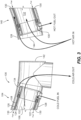
- the heat exchanger 104 includes an air passage 106 and a fuel passage 108, which are labeled in Fig. 3 .
- the air passage 106 and fuel passage 108 are in fluid isolation from one another, but are in thermal communication with one another for exchange of heat.
- the heat exchanger 104 is devoid of polymeric O-rings and seals inside the engine case 102, although it is possible to use a polymeric O-ring to seal between the heat exchanger 104 and the engine case 102 at the single port 110, where temperatures can be low enough to permit.
- Typical O-rings and polymeric seals do not permit temperatures in excess of about 500° F (260° C).
- Modern fuel temperatures can be roughly 900° F (482° C), and modern compressor discharge air temperatures can be in excess of 1000° F (540° C).
- a plurality of fuel injectors 116 are in fluid communication with the fuel manifold 112 for issuing atomized air and fuel into the combustor 118 that is included within the engine case 102.
- Fig. 1 is a cross-section that only shows one fuel injector 116, however those skilled in the art will readily appreciate that a plurality of conventional or multipoint injectors 116 are circumferentially distributed around the annular geometry of the system 100.
- the combustor 118 includes a combustor dome 120 operatively connected with the fuel injectors 116 for issuing an atomized mix of compressor discharge air and fuel into the combustor 118 for combustion.
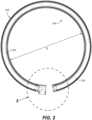
- the heat exchanger 104 includes a toroidal, double walled tube 122.
- the fuel passage 108 is defined between inner wall 124 and the outer walls 126 of the double walled tube 122.
- the heat exchanger 104 includes an outer tube 128 outside of the double walled tube 122.
- the air passage 106 includes first, a space 130 between the outer tube 128 and the outer wall 126 of the double walled tube 122 and second, a space 132 inward of the inner wall 124 of the double walled tube 122. The air passage 106 therefore exchanges heat on both the inside and outside of the double walled tube 122.
- the double wall tube 122 and outer tube 128 can be one in a plurality of similar heat exchanger ring 146.
- the heat exchanger rings 146 can be connected to an air outlet manifold 148 with a single air outlet fitting 142 for outletting air from all of the heat exchanger rings 146, e.g. the air outlet manifold 148 collects the outlet air from all of the heat exchanger rings 146 and routes it all out the outlet fitting 142, which can issue the cooled air through the port 110 in Fig. 1 .
- This inlet/outlet arrangement for the fuel and air makes the heat exchanger 104 a counter-flow heat exchanger, which can minimize thermal stress.
- a method includes feeding compressor discharge air (indicated by arrow 148) into a heat exchanger 104 located inside an engine case 102 and feeding fuel into the heat exchanger, as indicated by arrow 150.
- the method includes transferring heat from the compressor discharge air to the fuel in the heat exchanger 104. This cools the portion of the compressor discharge air in the heat exchanger 104 (this portion is indicated by arrow 152), and preheats the fuel in the heat exchanger 104.
- the method can include outletting the compressor discharge air from the heat exchanger 104 through a wall 154 of the engine case 102 to an exterior of the engine case 102.
- the method can include outletting the fuel from the heat exchanger 104 to a fuel manifold 112, distributing the fuel from the manifold 112 to a plurality of fuel injectors 116, and combusting the fuel in a combustor 118 connected to the fuel injectors 116.
- tubular geometry for the heat exchanger rings 146 allows placement of the heat exchanger 104 inside a high pressure engine case 102. Using tubing also reduces the number of sealed connections and allows for ease of inspection.
- Systems and methods as disclosed herein can reduce or eliminate risk of hot fuel leakage anywhere external to an engine. There is also a reduced or eliminated risk of damage to the hot fuel system such as from ballistic objects like FOD (foreign object debris) striking the hot fuel components. Locating heat exchangers within engine cases, close to fuel manifolds, can reduce weight, cost, and risk.
Landscapes
- Engineering & Computer Science (AREA)
- Mechanical Engineering (AREA)
- General Engineering & Computer Science (AREA)
- Chemical & Material Sciences (AREA)
- Combustion & Propulsion (AREA)
- Physics & Mathematics (AREA)
- Thermal Sciences (AREA)
- Heat-Exchange Devices With Radiators And Conduit Assemblies (AREA)
Claims (14)
- Système (100) comprenant :un carter de moteur (102) ; etun échangeur de chaleur (104) à l'intérieur du carter de moteur, dans lequel l'échangeur de chaleur comporte un passage d'air (106) et un passage de carburant (108), dans lequel le passage d'air et le passage de carburant sont isolés fluidiquement l'un de l'autre, mais sont en communication thermique l'un avec l'autre pour un échange de chaleur ; dans lequel l'échangeur de chaleur comporte un tube toroïdal à double paroi (122), dans lequel le passage de carburant est défini entre les parois interne (124) et externe (126) du tube à double paroi ;dans lequel l'échangeur de chaleur comporte un tube externe (128) à l'extérieur du tube à double paroi, dans lequel le passage d'air comporte :un espace (130) entre le tube externe et la paroi externe du tube à double paroi ; etun espace (132) vers l'intérieur de la paroi interne du tube à double paroi ; le système étant caractérisé en ce queune extrémité ouverte faisant face à la circonférence (144) du tube externe est une entrée depuis un espace à l'intérieur du carter de moteur dans l'espace entre le tube externe et la paroi externe du tube à double paroi et vers l'espace vers l'intérieur de la paroi interne du tube à double paroi, et dans lequel un raccord de sortie d'air (142) relié à l'extrémité circonférentielle opposée du tube externe (128) a une sortie unique à la fois pour l'espace entre le tube externe et la paroi externe du tube à double paroi et pour l'espace vers l'intérieur de la paroi interne du tube à double paroi.
- Système selon la revendication 1, dans lequel il y a un orifice unique (110) à travers le carter du moteur pour fournir de l'air de refroidissement à l'extérieur de carter de moteur depuis l'échangeur de chaleur.
- Système selon la revendication 2, dans lequel l'échangeur de chaleur est dépourvu de joints toriques polymères à l'intérieur du carter de moteur ; et comprenant éventuellement en outre un joint torique polymère d'étanchéité entre l'échangeur de chaleur et le carter de moteur au niveau de l'orifice unique.
- Système selon une quelconque revendication précédente, comprenant en outre un collecteur de carburant (112) à l'intérieur du carter de moteur en communication fluidique avec le passage de carburant de l'échangeur de chaleur pour fournir du carburant depuis l'échangeur de chaleur jusqu'au collecteur de carburant.
- Système selon la revendication 4, dans lequel une connexion rigide (114) relie l'échangeur de chaleur au collecteur de carburant.
- Système selon la revendication 4 ou 5, comprenant en outre une pluralité d'injecteurs de carburant (116) en communication fluidique avec le collecteur de carburant ; et éventuellement comprenant en outre une chambre de combustion (118) à l'intérieur du carter de moteur, dans lequel la chambre de combustion comporte un dôme de chambre de combustion (120) relié de manière fonctionnelle aux injecteurs de carburant pour délivrer un mélange atomisé d'air de décharge de compresseur et de carburant dans la chambre de combustion pour une combustion.
- Système selon la revendication 1, comprenant en outre un raccord d'entrée de carburant (134) au niveau d'une première extrémité circonférentielle (136) du tube à double paroi, et un raccord de sortie de carburant (138) au niveau d'une seconde extrémité (140) du tube à double paroi, dans lequel le raccord d'entrée de carburant et le raccord de sortie de carburant assurent une communication fluidique pour le passage de carburant à travers le tube à double paroi.
- Système selon la revendication 7, dans lequel le raccord de sortie d'air (142) est relié à une première extrémité circonférentielle du tube externe pour une communication fluidique de l'air depuis le passage d'air hors du tube externe.
- Système selon la revendication 8, dans lequel le tube à double paroi et le tube externe sont un premier anneau d'échangeur de chaleur (146), et comprenant en outre au moins un anneau d'échangeur de chaleur supplémentaire (146).
- Système selon la revendication 9, dans lequel le premier anneau d'échangeur de chaleur et l'au moins un anneau d'échangeur de chaleur supplémentaire sont reliés à un collecteur de sortie d'air (148) avec un raccord de sortie d'air unique (142) pour évacuer l'air du premier anneau d'échangeur de chaleur et de l'au moins un anneau d'échangeur de chaleur supplémentaire ; et/ou dans lequel le premier anneau d'échangeur de chaleur et l'au moins un anneau d'échangeur de chaleur supplémentaire sont disposés axialement dans l'ordre du plus grand diamètre de tore au plus petit dans une direction allant de l'amont vers l'aval par rapport au carter de moteur.
- Procédé d'utilisation du système selon la revendication 1, le procédé comprenant :l'introduction de l'air de décharge de compresseur dans l'échangeur de chaleur (140) situé à l'intérieur du carter de moteur (102) ;l'introduction de carburant dans l'échangeur de chaleur ; etle transfert de chaleur de l'air de décharge de compresseur au carburant dans l'échangeur de chaleur.
- Procédé selon la revendication 11, comprenant en outre l'évacuation de l'air de décharge de compresseur depuis l'échangeur de chaleur à travers une paroi (154) du carter de moteur vers un extérieur du carter de moteur.
- Procédé selon la revendication 11 ou 12, comprenant en outre l'évacuation du carburant depuis l'échangeur de chaleur vers un collecteur de carburant (112).
- Procédé selon la revendication 13, comprenant en outre la distribution du carburant depuis le collecteur vers une pluralité d'injecteurs de carburant (116) ; et comprenant éventuellement en outre la combustion du carburant dans une chambre de combustion reliée aux injecteurs de carburant.
Applications Claiming Priority (1)
| Application Number | Priority Date | Filing Date | Title |
|---|---|---|---|
| US16/696,624 US11274601B2 (en) | 2019-11-26 | 2019-11-26 | Internal fuel/air heat exchangers |
Publications (2)
| Publication Number | Publication Date |
|---|---|
| EP3828399A1 EP3828399A1 (fr) | 2021-06-02 |
| EP3828399B1 true EP3828399B1 (fr) | 2023-11-08 |
Family
ID=73455597
Family Applications (1)
| Application Number | Title | Priority Date | Filing Date |
|---|---|---|---|
| EP20208050.3A Active EP3828399B1 (fr) | 2019-11-26 | 2020-11-17 | Échangeur air/carburant interne |
Country Status (2)
| Country | Link |
|---|---|
| US (1) | US11274601B2 (fr) |
| EP (1) | EP3828399B1 (fr) |
Cited By (1)
| Publication number | Priority date | Publication date | Assignee | Title |
|---|---|---|---|---|
| EP4711675A1 (fr) * | 2024-09-16 | 2026-03-18 | General Electric Company | Section de combustion pour une turbomachine |
Families Citing this family (6)
| Publication number | Priority date | Publication date | Assignee | Title |
|---|---|---|---|---|
| KR102083611B1 (ko) * | 2019-04-25 | 2020-03-02 | 엘지이노텍 주식회사 | 열변환장치 |
| US11519332B1 (en) * | 2021-05-11 | 2022-12-06 | Rolls-Royce North American Technologies Inc. | Fuel injector with integrated heat exchanger for use in gas turbine engines |
| US11846422B2 (en) | 2021-08-19 | 2023-12-19 | Collins Engine Nozzles, Inc. | Systems for fuel injectors with fuel air heat exchangers |
| US11555450B1 (en) | 2021-08-19 | 2023-01-17 | Collins Engine Nozzles, Inc. | Fuel injectors with heat exchangers |
| US20240359812A1 (en) * | 2022-07-22 | 2024-10-31 | Rtx Corporation | Multiple heat source cryogenic bottoming cycle sequencing and routing |
| GB202317342D0 (en) * | 2023-11-13 | 2023-12-27 | Rolls Royce Plc | Gas turbine engine hydrogen fuel system |
Family Cites Families (8)
| Publication number | Priority date | Publication date | Assignee | Title |
|---|---|---|---|---|
| US9284231B2 (en) * | 2011-12-16 | 2016-03-15 | General Electric Company | Hydrocarbon film protected refractory carbide components and use |
| US9109842B2 (en) | 2012-02-24 | 2015-08-18 | Pratt & Whitney Canada Corp. | Fuel air heat exchanger |
| GB201410607D0 (en) * | 2014-06-13 | 2014-07-30 | Rolls Royce Plc | A fuel manifold and fuel injector arrangement |
| GB201514651D0 (en) * | 2015-08-18 | 2015-09-30 | Rolls Royce Plc | Sealing arrangements |
| US10626798B2 (en) | 2015-12-09 | 2020-04-21 | United Technologies Corporation | Diffuser mounted fuel-air heat exchanger |
| US10830150B2 (en) * | 2016-01-28 | 2020-11-10 | Rolls-Royce Corporation | Fuel heat exchanger with leak management |
| CA3000372A1 (fr) | 2017-05-11 | 2018-11-11 | Rolls-Royce North American Technologies, Inc. | Echangeur thermique integre comportant une buse de carburant |
| US20190063322A1 (en) * | 2017-08-22 | 2019-02-28 | United Technologies Corporation | Hybrid floatwall cooling feature |
-
2019
- 2019-11-26 US US16/696,624 patent/US11274601B2/en active Active
-
2020
- 2020-11-17 EP EP20208050.3A patent/EP3828399B1/fr active Active
Cited By (1)
| Publication number | Priority date | Publication date | Assignee | Title |
|---|---|---|---|---|
| EP4711675A1 (fr) * | 2024-09-16 | 2026-03-18 | General Electric Company | Section de combustion pour une turbomachine |
Also Published As
| Publication number | Publication date |
|---|---|
| US11274601B2 (en) | 2022-03-15 |
| US20210156310A1 (en) | 2021-05-27 |
| EP3828399A1 (fr) | 2021-06-02 |
Similar Documents
| Publication | Publication Date | Title |
|---|---|---|
| EP3828399B1 (fr) | Échangeur air/carburant interne | |
| US10221768B2 (en) | Heat exchanger having a coaxial or concentric tube construction | |
| US10830147B2 (en) | Heat exchanger integrated with fuel nozzle | |
| US10830440B2 (en) | Combustion systems having bayonet features | |
| EP2530280B1 (fr) | Échangeur thermique d'air et de carburant | |
| EP3431878B1 (fr) | Buses de combustible | |
| US7383686B2 (en) | Secondary flow, high pressure turbine module cooling air system for recuperated gas turbine engines | |
| EP2902605B1 (fr) | Collecteur de carburant et dispositif d'injecteur de carburant pour turbine à gaz | |
| EP4137689A1 (fr) | Collecteurs d'air pour injecteurs de carburant avec des échangeurs de chaleur d'air et de carburant | |
| US20130283798A1 (en) | Combustor and a method for assembling the combustor | |
| EP3770502A1 (fr) | Collecteurs de carburant segmentés | |
| US20110186276A1 (en) | Heat exchanger assembly and method | |
| CA2764342C (fr) | Tube d'admission interne blinde pour collecteur de carburant a alimenta ion laterale | |
| EP4459186B1 (fr) | Moteur à turbine à gaz | |
| EP3460218B1 (fr) | Tubes de transfert | |
| RU2310086C1 (ru) | Газотурбинная установка |
Legal Events
| Date | Code | Title | Description |
|---|---|---|---|
| PUAI | Public reference made under article 153(3) epc to a published international application that has entered the european phase |
Free format text: ORIGINAL CODE: 0009012 |
|
| STAA | Information on the status of an ep patent application or granted ep patent |
Free format text: STATUS: THE APPLICATION HAS BEEN PUBLISHED |
|
| AK | Designated contracting states |
Kind code of ref document: A1 Designated state(s): AL AT BE BG CH CY CZ DE DK EE ES FI FR GB GR HR HU IE IS IT LI LT LU LV MC MK MT NL NO PL PT RO RS SE SI SK SM TR |
|
| STAA | Information on the status of an ep patent application or granted ep patent |
Free format text: STATUS: REQUEST FOR EXAMINATION WAS MADE |
|
| 17P | Request for examination filed |
Effective date: 20211202 |
|
| RBV | Designated contracting states (corrected) |
Designated state(s): AL AT BE BG CH CY CZ DE DK EE ES FI FR GB GR HR HU IE IS IT LI LT LU LV MC MK MT NL NO PL PT RO RS SE SI SK SM TR |
|
| RAP3 | Party data changed (applicant data changed or rights of an application transferred) |
Owner name: COLLINS ENGINE NOZZLES, INC. |
|
| GRAP | Despatch of communication of intention to grant a patent |
Free format text: ORIGINAL CODE: EPIDOSNIGR1 |
|
| RIC1 | Information provided on ipc code assigned before grant |
Ipc: F02C 7/224 20060101ALI20230418BHEP Ipc: F02C 6/08 20060101AFI20230418BHEP |
|
| STAA | Information on the status of an ep patent application or granted ep patent |
Free format text: STATUS: GRANT OF PATENT IS INTENDED |
|
| INTG | Intention to grant announced |
Effective date: 20230525 |
|
| GRAS | Grant fee paid |
Free format text: ORIGINAL CODE: EPIDOSNIGR3 |
|
| GRAA | (expected) grant |
Free format text: ORIGINAL CODE: 0009210 |
|
| STAA | Information on the status of an ep patent application or granted ep patent |
Free format text: STATUS: THE PATENT HAS BEEN GRANTED |
|
| P01 | Opt-out of the competence of the unified patent court (upc) registered |
Effective date: 20230922 |
|
| AK | Designated contracting states |
Kind code of ref document: B1 Designated state(s): AL AT BE BG CH CY CZ DE DK EE ES FI FR GB GR HR HU IE IS IT LI LT LU LV MC MK MT NL NO PL PT RO RS SE SI SK SM TR |
|
| REG | Reference to a national code |
Ref country code: GB Ref legal event code: FG4D |
|
| REG | Reference to a national code |
Ref country code: CH Ref legal event code: EP |
|
| REG | Reference to a national code |
Ref country code: DE Ref legal event code: R096 Ref document number: 602020020633 Country of ref document: DE |
|
| REG | Reference to a national code |
Ref country code: IE Ref legal event code: FG4D |
|
| REG | Reference to a national code |
Ref country code: LT Ref legal event code: MG9D |
|
| REG | Reference to a national code |
Ref country code: NL Ref legal event code: MP Effective date: 20231108 |
|
| PG25 | Lapsed in a contracting state [announced via postgrant information from national office to epo] |
Ref country code: GR Free format text: LAPSE BECAUSE OF FAILURE TO SUBMIT A TRANSLATION OF THE DESCRIPTION OR TO PAY THE FEE WITHIN THE PRESCRIBED TIME-LIMIT Effective date: 20240209 |
|
| PG25 | Lapsed in a contracting state [announced via postgrant information from national office to epo] |
Ref country code: IS Free format text: LAPSE BECAUSE OF FAILURE TO SUBMIT A TRANSLATION OF THE DESCRIPTION OR TO PAY THE FEE WITHIN THE PRESCRIBED TIME-LIMIT Effective date: 20240308 |
|
| PG25 | Lapsed in a contracting state [announced via postgrant information from national office to epo] |
Ref country code: LT Free format text: LAPSE BECAUSE OF FAILURE TO SUBMIT A TRANSLATION OF THE DESCRIPTION OR TO PAY THE FEE WITHIN THE PRESCRIBED TIME-LIMIT Effective date: 20231108 |
|
| REG | Reference to a national code |
Ref country code: AT Ref legal event code: MK05 Ref document number: 1629795 Country of ref document: AT Kind code of ref document: T Effective date: 20231108 |
|
| PG25 | Lapsed in a contracting state [announced via postgrant information from national office to epo] |
Ref country code: NL Free format text: LAPSE BECAUSE OF FAILURE TO SUBMIT A TRANSLATION OF THE DESCRIPTION OR TO PAY THE FEE WITHIN THE PRESCRIBED TIME-LIMIT Effective date: 20231108 |
|
| PG25 | Lapsed in a contracting state [announced via postgrant information from national office to epo] |
Ref country code: AT Free format text: LAPSE BECAUSE OF FAILURE TO SUBMIT A TRANSLATION OF THE DESCRIPTION OR TO PAY THE FEE WITHIN THE PRESCRIBED TIME-LIMIT Effective date: 20231108 |
|
| PG25 | Lapsed in a contracting state [announced via postgrant information from national office to epo] |
Ref country code: ES Free format text: LAPSE BECAUSE OF FAILURE TO SUBMIT A TRANSLATION OF THE DESCRIPTION OR TO PAY THE FEE WITHIN THE PRESCRIBED TIME-LIMIT Effective date: 20231108 |
|
| PG25 | Lapsed in a contracting state [announced via postgrant information from national office to epo] |
Ref country code: NL Free format text: LAPSE BECAUSE OF FAILURE TO SUBMIT A TRANSLATION OF THE DESCRIPTION OR TO PAY THE FEE WITHIN THE PRESCRIBED TIME-LIMIT Effective date: 20231108 Ref country code: LT Free format text: LAPSE BECAUSE OF FAILURE TO SUBMIT A TRANSLATION OF THE DESCRIPTION OR TO PAY THE FEE WITHIN THE PRESCRIBED TIME-LIMIT Effective date: 20231108 Ref country code: IS Free format text: LAPSE BECAUSE OF FAILURE TO SUBMIT A TRANSLATION OF THE DESCRIPTION OR TO PAY THE FEE WITHIN THE PRESCRIBED TIME-LIMIT Effective date: 20240308 Ref country code: GR Free format text: LAPSE BECAUSE OF FAILURE TO SUBMIT A TRANSLATION OF THE DESCRIPTION OR TO PAY THE FEE WITHIN THE PRESCRIBED TIME-LIMIT Effective date: 20240209 Ref country code: ES Free format text: LAPSE BECAUSE OF FAILURE TO SUBMIT A TRANSLATION OF THE DESCRIPTION OR TO PAY THE FEE WITHIN THE PRESCRIBED TIME-LIMIT Effective date: 20231108 Ref country code: BG Free format text: LAPSE BECAUSE OF FAILURE TO SUBMIT A TRANSLATION OF THE DESCRIPTION OR TO PAY THE FEE WITHIN THE PRESCRIBED TIME-LIMIT Effective date: 20240208 Ref country code: AT Free format text: LAPSE BECAUSE OF FAILURE TO SUBMIT A TRANSLATION OF THE DESCRIPTION OR TO PAY THE FEE WITHIN THE PRESCRIBED TIME-LIMIT Effective date: 20231108 Ref country code: PT Free format text: LAPSE BECAUSE OF FAILURE TO SUBMIT A TRANSLATION OF THE DESCRIPTION OR TO PAY THE FEE WITHIN THE PRESCRIBED TIME-LIMIT Effective date: 20240308 |
|
| PG25 | Lapsed in a contracting state [announced via postgrant information from national office to epo] |
Ref country code: SE Free format text: LAPSE BECAUSE OF FAILURE TO SUBMIT A TRANSLATION OF THE DESCRIPTION OR TO PAY THE FEE WITHIN THE PRESCRIBED TIME-LIMIT Effective date: 20231108 Ref country code: RS Free format text: LAPSE BECAUSE OF FAILURE TO SUBMIT A TRANSLATION OF THE DESCRIPTION OR TO PAY THE FEE WITHIN THE PRESCRIBED TIME-LIMIT Effective date: 20231108 Ref country code: PL Free format text: LAPSE BECAUSE OF FAILURE TO SUBMIT A TRANSLATION OF THE DESCRIPTION OR TO PAY THE FEE WITHIN THE PRESCRIBED TIME-LIMIT Effective date: 20231108 Ref country code: NO Free format text: LAPSE BECAUSE OF FAILURE TO SUBMIT A TRANSLATION OF THE DESCRIPTION OR TO PAY THE FEE WITHIN THE PRESCRIBED TIME-LIMIT Effective date: 20240208 Ref country code: LV Free format text: LAPSE BECAUSE OF FAILURE TO SUBMIT A TRANSLATION OF THE DESCRIPTION OR TO PAY THE FEE WITHIN THE PRESCRIBED TIME-LIMIT Effective date: 20231108 Ref country code: HR Free format text: LAPSE BECAUSE OF FAILURE TO SUBMIT A TRANSLATION OF THE DESCRIPTION OR TO PAY THE FEE WITHIN THE PRESCRIBED TIME-LIMIT Effective date: 20231108 |
|
| REG | Reference to a national code |
Ref country code: CH Ref legal event code: PL |
|
| PG25 | Lapsed in a contracting state [announced via postgrant information from national office to epo] |
Ref country code: DK Free format text: LAPSE BECAUSE OF FAILURE TO SUBMIT A TRANSLATION OF THE DESCRIPTION OR TO PAY THE FEE WITHIN THE PRESCRIBED TIME-LIMIT Effective date: 20231108 |
|
| PG25 | Lapsed in a contracting state [announced via postgrant information from national office to epo] |
Ref country code: LU Free format text: LAPSE BECAUSE OF NON-PAYMENT OF DUE FEES Effective date: 20231117 |
|
| PG25 | Lapsed in a contracting state [announced via postgrant information from national office to epo] |
Ref country code: CH Free format text: LAPSE BECAUSE OF NON-PAYMENT OF DUE FEES Effective date: 20231130 |
|
| PG25 | Lapsed in a contracting state [announced via postgrant information from national office to epo] |
Ref country code: CZ Free format text: LAPSE BECAUSE OF FAILURE TO SUBMIT A TRANSLATION OF THE DESCRIPTION OR TO PAY THE FEE WITHIN THE PRESCRIBED TIME-LIMIT Effective date: 20231108 |
|
| PG25 | Lapsed in a contracting state [announced via postgrant information from national office to epo] |
Ref country code: SK Free format text: LAPSE BECAUSE OF FAILURE TO SUBMIT A TRANSLATION OF THE DESCRIPTION OR TO PAY THE FEE WITHIN THE PRESCRIBED TIME-LIMIT Effective date: 20231108 |
|
| PG25 | Lapsed in a contracting state [announced via postgrant information from national office to epo] |
Ref country code: SM Free format text: LAPSE BECAUSE OF FAILURE TO SUBMIT A TRANSLATION OF THE DESCRIPTION OR TO PAY THE FEE WITHIN THE PRESCRIBED TIME-LIMIT Effective date: 20231108 Ref country code: SK Free format text: LAPSE BECAUSE OF FAILURE TO SUBMIT A TRANSLATION OF THE DESCRIPTION OR TO PAY THE FEE WITHIN THE PRESCRIBED TIME-LIMIT Effective date: 20231108 Ref country code: RO Free format text: LAPSE BECAUSE OF FAILURE TO SUBMIT A TRANSLATION OF THE DESCRIPTION OR TO PAY THE FEE WITHIN THE PRESCRIBED TIME-LIMIT Effective date: 20231108 Ref country code: LU Free format text: LAPSE BECAUSE OF NON-PAYMENT OF DUE FEES Effective date: 20231117 Ref country code: IT Free format text: LAPSE BECAUSE OF FAILURE TO SUBMIT A TRANSLATION OF THE DESCRIPTION OR TO PAY THE FEE WITHIN THE PRESCRIBED TIME-LIMIT Effective date: 20231108 Ref country code: EE Free format text: LAPSE BECAUSE OF FAILURE TO SUBMIT A TRANSLATION OF THE DESCRIPTION OR TO PAY THE FEE WITHIN THE PRESCRIBED TIME-LIMIT Effective date: 20231108 Ref country code: DK Free format text: LAPSE BECAUSE OF FAILURE TO SUBMIT A TRANSLATION OF THE DESCRIPTION OR TO PAY THE FEE WITHIN THE PRESCRIBED TIME-LIMIT Effective date: 20231108 Ref country code: CZ Free format text: LAPSE BECAUSE OF FAILURE TO SUBMIT A TRANSLATION OF THE DESCRIPTION OR TO PAY THE FEE WITHIN THE PRESCRIBED TIME-LIMIT Effective date: 20231108 Ref country code: CH Free format text: LAPSE BECAUSE OF NON-PAYMENT OF DUE FEES Effective date: 20231130 |
|
| REG | Reference to a national code |
Ref country code: BE Ref legal event code: MM Effective date: 20231130 |
|
| REG | Reference to a national code |
Ref country code: DE Ref legal event code: R097 Ref document number: 602020020633 Country of ref document: DE |
|
| PG25 | Lapsed in a contracting state [announced via postgrant information from national office to epo] |
Ref country code: MC Free format text: LAPSE BECAUSE OF FAILURE TO SUBMIT A TRANSLATION OF THE DESCRIPTION OR TO PAY THE FEE WITHIN THE PRESCRIBED TIME-LIMIT Effective date: 20231108 |
|
| PG25 | Lapsed in a contracting state [announced via postgrant information from national office to epo] |
Ref country code: MC Free format text: LAPSE BECAUSE OF FAILURE TO SUBMIT A TRANSLATION OF THE DESCRIPTION OR TO PAY THE FEE WITHIN THE PRESCRIBED TIME-LIMIT Effective date: 20231108 |
|
| REG | Reference to a national code |
Ref country code: IE Ref legal event code: MM4A |
|
| PLBE | No opposition filed within time limit |
Free format text: ORIGINAL CODE: 0009261 |
|
| STAA | Information on the status of an ep patent application or granted ep patent |
Free format text: STATUS: NO OPPOSITION FILED WITHIN TIME LIMIT |
|
| PG25 | Lapsed in a contracting state [announced via postgrant information from national office to epo] |
Ref country code: IE Free format text: LAPSE BECAUSE OF NON-PAYMENT OF DUE FEES Effective date: 20231117 |
|
| PG25 | Lapsed in a contracting state [announced via postgrant information from national office to epo] |
Ref country code: BE Free format text: LAPSE BECAUSE OF NON-PAYMENT OF DUE FEES Effective date: 20231130 |
|
| 26N | No opposition filed |
Effective date: 20240809 |
|
| PG25 | Lapsed in a contracting state [announced via postgrant information from national office to epo] |
Ref country code: SI Free format text: LAPSE BECAUSE OF FAILURE TO SUBMIT A TRANSLATION OF THE DESCRIPTION OR TO PAY THE FEE WITHIN THE PRESCRIBED TIME-LIMIT Effective date: 20231108 |
|
| PG25 | Lapsed in a contracting state [announced via postgrant information from national office to epo] |
Ref country code: SI Free format text: LAPSE BECAUSE OF FAILURE TO SUBMIT A TRANSLATION OF THE DESCRIPTION OR TO PAY THE FEE WITHIN THE PRESCRIBED TIME-LIMIT Effective date: 20231108 Ref country code: IE Free format text: LAPSE BECAUSE OF NON-PAYMENT OF DUE FEES Effective date: 20231117 Ref country code: BE Free format text: LAPSE BECAUSE OF NON-PAYMENT OF DUE FEES Effective date: 20231130 |
|
| PG25 | Lapsed in a contracting state [announced via postgrant information from national office to epo] |
Ref country code: FI Free format text: LAPSE BECAUSE OF FAILURE TO SUBMIT A TRANSLATION OF THE DESCRIPTION OR TO PAY THE FEE WITHIN THE PRESCRIBED TIME-LIMIT Effective date: 20231108 |
|
| PG25 | Lapsed in a contracting state [announced via postgrant information from national office to epo] |
Ref country code: CY Free format text: LAPSE BECAUSE OF FAILURE TO SUBMIT A TRANSLATION OF THE DESCRIPTION OR TO PAY THE FEE WITHIN THE PRESCRIBED TIME-LIMIT; INVALID AB INITIO Effective date: 20201117 |
|
| PG25 | Lapsed in a contracting state [announced via postgrant information from national office to epo] |
Ref country code: HU Free format text: LAPSE BECAUSE OF FAILURE TO SUBMIT A TRANSLATION OF THE DESCRIPTION OR TO PAY THE FEE WITHIN THE PRESCRIBED TIME-LIMIT; INVALID AB INITIO Effective date: 20201117 |
|
| PG25 | Lapsed in a contracting state [announced via postgrant information from national office to epo] |
Ref country code: TR Free format text: LAPSE BECAUSE OF FAILURE TO SUBMIT A TRANSLATION OF THE DESCRIPTION OR TO PAY THE FEE WITHIN THE PRESCRIBED TIME-LIMIT Effective date: 20231108 |
|
| PGFP | Annual fee paid to national office [announced via postgrant information from national office to epo] |
Ref country code: DE Payment date: 20251022 Year of fee payment: 6 |
|
| PGFP | Annual fee paid to national office [announced via postgrant information from national office to epo] |
Ref country code: GB Payment date: 20251023 Year of fee payment: 6 |
|
| PGFP | Annual fee paid to national office [announced via postgrant information from national office to epo] |
Ref country code: FR Payment date: 20251022 Year of fee payment: 6 |