EP3828526B1 - Pfadlängenkalibrierungssystem und -verfahren - Google Patents
Pfadlängenkalibrierungssystem und -verfahren Download PDFInfo
- Publication number
- EP3828526B1 EP3828526B1 EP20179928.5A EP20179928A EP3828526B1 EP 3828526 B1 EP3828526 B1 EP 3828526B1 EP 20179928 A EP20179928 A EP 20179928A EP 3828526 B1 EP3828526 B1 EP 3828526B1
- Authority
- EP
- European Patent Office
- Prior art keywords
- magnetic flux
- optical
- flux sensor
- coupled
- magnet
- Prior art date
- Legal status (The legal status is an assumption and is not a legal conclusion. Google has not performed a legal analysis and makes no representation as to the accuracy of the status listed.)
- Active
Links
Images


Classifications
-
- G—PHYSICS
- G01—MEASURING; TESTING
- G01N—INVESTIGATING OR ANALYSING MATERIALS BY DETERMINING THEIR CHEMICAL OR PHYSICAL PROPERTIES
- G01N21/00—Investigating or analysing materials by the use of optical means, i.e. using sub-millimetre waves, infrared, visible or ultraviolet light
- G01N21/01—Arrangements or apparatus for facilitating the optical investigation
- G01N21/03—Cuvette constructions
- G01N21/0303—Optical path conditioning in cuvettes, e.g. windows; adapted optical elements or systems; path modifying or adjustment
-
- G—PHYSICS
- G01—MEASURING; TESTING
- G01N—INVESTIGATING OR ANALYSING MATERIALS BY DETERMINING THEIR CHEMICAL OR PHYSICAL PROPERTIES
- G01N21/00—Investigating or analysing materials by the use of optical means, i.e. using sub-millimetre waves, infrared, visible or ultraviolet light
- G01N21/17—Systems in which incident light is modified in accordance with the properties of the material investigated
- G01N21/25—Colour; Spectral properties, i.e. comparison of effect of material on the light at two or more different wavelengths or wavelength bands
- G01N21/27—Colour; Spectral properties, i.e. comparison of effect of material on the light at two or more different wavelengths or wavelength bands using photo-electric detection ; circuits for computing concentration
-
- G—PHYSICS
- G01—MEASURING; TESTING
- G01N—INVESTIGATING OR ANALYSING MATERIALS BY DETERMINING THEIR CHEMICAL OR PHYSICAL PROPERTIES
- G01N21/00—Investigating or analysing materials by the use of optical means, i.e. using sub-millimetre waves, infrared, visible or ultraviolet light
- G01N21/17—Systems in which incident light is modified in accordance with the properties of the material investigated
- G01N21/25—Colour; Spectral properties, i.e. comparison of effect of material on the light at two or more different wavelengths or wavelength bands
- G01N21/31—Investigating relative effect of material at wavelengths characteristic of specific elements or molecules, e.g. atomic absorption spectrometry
-
- G—PHYSICS
- G01—MEASURING; TESTING
- G01R—MEASURING ELECTRIC VARIABLES; MEASURING MAGNETIC VARIABLES
- G01R33/00—Arrangements or instruments for measuring magnetic variables
- G01R33/02—Measuring direction or magnitude of magnetic fields or magnetic flux
- G01R33/06—Measuring direction or magnitude of magnetic fields or magnetic flux using galvano-magnetic devices
- G01R33/07—Hall effect devices
-
- G—PHYSICS
- G01—MEASURING; TESTING
- G01R—MEASURING ELECTRIC VARIABLES; MEASURING MAGNETIC VARIABLES
- G01R33/00—Arrangements or instruments for measuring magnetic variables
- G01R33/02—Measuring direction or magnitude of magnetic fields or magnetic flux
- G01R33/06—Measuring direction or magnitude of magnetic fields or magnetic flux using galvano-magnetic devices
- G01R33/09—Magnetoresistive devices
- G01R33/093—Magnetoresistive devices using multilayer structures, e.g. giant magnetoresistance sensors
-
- G—PHYSICS
- G01—MEASURING; TESTING
- G01D—MEASURING NOT SPECIALLY ADAPTED FOR A SPECIFIC VARIABLE; ARRANGEMENTS FOR MEASURING TWO OR MORE VARIABLES NOT COVERED IN A SINGLE OTHER SUBCLASS; TARIFF METERING APPARATUS; MEASURING OR TESTING NOT OTHERWISE PROVIDED FOR
- G01D5/00—Mechanical means for transferring the output of a sensing member; Means for converting the output of a sensing member to another variable where the form or nature of the sensing member does not constrain the means for converting; Transducers not specially adapted for a specific variable
- G01D5/12—Mechanical means for transferring the output of a sensing member; Means for converting the output of a sensing member to another variable where the form or nature of the sensing member does not constrain the means for converting; Transducers not specially adapted for a specific variable using electric or magnetic means
- G01D5/14—Mechanical means for transferring the output of a sensing member; Means for converting the output of a sensing member to another variable where the form or nature of the sensing member does not constrain the means for converting; Transducers not specially adapted for a specific variable using electric or magnetic means influencing the magnitude of a current or voltage
- G01D5/142—Mechanical means for transferring the output of a sensing member; Means for converting the output of a sensing member to another variable where the form or nature of the sensing member does not constrain the means for converting; Transducers not specially adapted for a specific variable using electric or magnetic means influencing the magnitude of a current or voltage using Hall-effect devices
- G01D5/145—Mechanical means for transferring the output of a sensing member; Means for converting the output of a sensing member to another variable where the form or nature of the sensing member does not constrain the means for converting; Transducers not specially adapted for a specific variable using electric or magnetic means influencing the magnitude of a current or voltage using Hall-effect devices influenced by the relative movement between the Hall device and magnetic fields
-
- G—PHYSICS
- G01—MEASURING; TESTING
- G01N—INVESTIGATING OR ANALYSING MATERIALS BY DETERMINING THEIR CHEMICAL OR PHYSICAL PROPERTIES
- G01N21/00—Investigating or analysing materials by the use of optical means, i.e. using sub-millimetre waves, infrared, visible or ultraviolet light
- G01N21/01—Arrangements or apparatus for facilitating the optical investigation
- G01N21/03—Cuvette constructions
- G01N2021/0346—Capillary cells; Microcells
- G01N2021/035—Supports for sample drops
-
- G—PHYSICS
- G01—MEASURING; TESTING
- G01N—INVESTIGATING OR ANALYSING MATERIALS BY DETERMINING THEIR CHEMICAL OR PHYSICAL PROPERTIES
- G01N21/00—Investigating or analysing materials by the use of optical means, i.e. using sub-millimetre waves, infrared, visible or ultraviolet light
- G01N21/01—Arrangements or apparatus for facilitating the optical investigation
- G01N21/03—Cuvette constructions
- G01N2021/036—Cuvette constructions transformable, modifiable
-
- G—PHYSICS
- G01—MEASURING; TESTING
- G01N—INVESTIGATING OR ANALYSING MATERIALS BY DETERMINING THEIR CHEMICAL OR PHYSICAL PROPERTIES
- G01N2201/00—Features of devices classified in G01N21/00
- G01N2201/06—Illumination; Optics
- G01N2201/066—Modifiable path; multiple paths in one sample
- G01N2201/0668—Multiple paths; optimisable path length
-
- G—PHYSICS
- G01—MEASURING; TESTING
- G01N—INVESTIGATING OR ANALYSING MATERIALS BY DETERMINING THEIR CHEMICAL OR PHYSICAL PROPERTIES
- G01N2201/00—Features of devices classified in G01N21/00
- G01N2201/08—Optical fibres; light guides
Definitions
- the invention is generally related to path length calibration for an apparatus for measuring an optical property of a sample.
- Liquids, mixtures, solutions and reacting mixtures are often characterized using optical techniques such as spectrophotometry.
- the liquid is usually contained in a vessel referred to as a cell or cuvette, two or more of whose sides are of optical quality and permit the passage of those wavelengths needed to characterize the liquid contained therein.
- a cell or cuvette two or more of whose sides are of optical quality and permit the passage of those wavelengths needed to characterize the liquid contained therein.
- micro-volume UV/Vis spectrophotometers described, for example, in US Patent No. 6,628,382 B2 , measure the absorbance of microliter amounts of liquid samples via a sample retention technology which enables containing a liquid sample by its surface tension between surfaces 2 and 7.
- the liquid sample forms a column 9 between a light receiving sample interface 7 typically coupled to a first optical conduit such as an optical fiber 11, and a light transmitting sample interface 2, which is typically coupled to a second optical conduit such as an optical fiber 6.
- the upper 2 and lower 7 sample interfaces can be moved in relation to one another to create multiple known path lengths that are typically less than or equal to 1 mm, thereby expanding the dynamic range of the spectrophotometer for a particular sample, as described in US Patent No.
- Light 3 from a light source coming through the fiber 6 contained in and flush with surface 2 (also referenced herein as the upper sample interface, or first pedestal surface) radiates downward through the liquid sample column 9 and is collected by the fiber 11 in the lower surface 7 (also referenced herein as the second pedestal surface) of the lower sample interface 4 and sent on to the analysis spectrometer for absorbance measurements.
- the placement of the liquid sample is achieved by the user manually pipetting a sample (typically a microliter or two) directly onto the lower sample interface.
- the absorbance of the sample is measured by taking the negative log of the ratio of the amount of light (I 0 ) transmitted through the system in the absence of the sample and the amount of light (I) transmitted through the system when the sample is present in the sampling interface.
- the amount of light transmitted through the system when the sample is present in the sampling interface is directly proportional to the path length and the concentration of the sample, in accordance with the Beer-Lambert law.
- micro-volume UV/Vis spectrophotometers e.g., NanoDrop TM , Thermo Electron Scientific Instruments, Madison WI
- NanoDrop TM Thermo Electron Scientific Instruments, Madison WI
- US 2014/008539 A1 is directed at a motorized variable path length cell for spectroscopy.
- US 7,088,095 B1 discloses a magnetic linear displacement sensor comprising a Hall transducer element having a sensor plate surface and at least one magnet having a lengthwise dimension along which said Hall element detects a magnetic field component orthogonal to the sensor plate surface during displacement sensing.
- EP 2 166 313 A1 discloses a magnetic sensor for determining a position of a transmitter magnet along a path with a plurality of sensor elements, as well as control electronics for obtaining a sensor element signal of one of the sensor elements.
- US 2006/049826 A1 is directed at MEMS systems in optical communication systems.
- an apparatus for measuring a property of a sample in accordance with claim 1 includes inter alia a magnet, a base plate, a mechanical stop coupled to the base plate, and a second pedestal surface mechanically coupled to said base plate and configured to receive a liquid sample.
- the second pedestal surface is coupled to a spectrometer, wherein said second pedestal surface is further operable so as to adjust a separation between the first and the second pedestal surfaces at a variable distance (P) to pull the liquid sample into a column so as to be contained by surface tension, or to squeeze the sample during optical analysis, thereby providing an optical path for photometric or spectrometric measurement.
- P variable distance
- the apparatus further includes a magnetic flux sensor located between north and south magnetic flux fields of the magnet such that the magnetic flux reaching the sensor while the mechanical stop is in physical contact with the swing arm provides a range of output of the magnetic flux sensor, such as a linear range of output of the magnetic flux sensor.
- the apparatus also includes a processor adapted to calibrate the point for minimum optical path length by utilizing a threshold magnetic flux field emitted from the magnet and detected by the magnetic flux sensor.
- the apparatus further includes a first optical conduit coupled to the first pedestal surface.
- the apparatus further includes a second optical conduit coupled to the second pedestal surface.
- the apparatus can further include a bracket configured to permit translational movement of said second optical conduit parallel to a longitudinal axis of said second optical conduit.
- the magnetic flux sensor can be, for example, a linear Hall effect sensor or a giant magnetoresistive (GMR) sensor.
- the magnetic flux sensor can be located such that a null plane of north and south magnetic flux fields of the magnet is centered on the magnetic flux sensor while the mechanical stop is in physical contact with the swing arm.
- the first optical conduit includes a transmitting end and the second optical conduit includes a receiving end, with said transmitting end of said first optical conduit and said receiving end of said second optical conduit providing the optical path for photometric or spectrometric measurement.
- the first optical conduit includes a receiving end and the second optical conduit includes a transmitting end, with said receiving end of said first optical conduit and said transmitting end of said second optical conduit providing the optical path for photometric or spectrometric measurement.
- the magnet is coupled to the swing arm, and the magnetic flux sensor is coupled to the base plate, or the magnetic flux sensor is coupled to the swing arm, and the magnet is coupled to the base plate.
- the bracket can further include a position sensor that provides feedback so as to enable precision displacement between said first and said second pedestal surfaces so as to enable said variable distance (P).
- the position sensor can further establish a reference position when a translation control system initializes upon startup or upon being interrupted by an opto-interrupter device coupled to said second optical conduit.
- the apparatus can measure absorbances in a range of between about 0.005 Absorbance Units and about 2.0 Absorbance Units for any given optical path length.
- the first and second optical conduits can include at least one optical fiber selected from: a single-mode fiber, a polarization maintaining fiber, and a multi-mode fiber.
- the light source can be configured to provide optical wavelengths in a range of between about 190 nm and about 850 nm.
- a method of measuring an optical property of a sample in accordance with claim 14 includes inter alia coupling a second pedestal surface to said base plate, the second pedestal surface configured to receive a liquid sample and further operable so as to adjust a separation between said first and said second pedestal surfaces at a variable distance (P) to pull said liquid sample into a column so as to be contained by surface tension, or to squeeze the sample during optical analysis, thereby providing an optical path for photometric or spectrometric measurement.
- P variable distance
- the method also includes locating the magnetic flux sensor between north and south magnetic flux fields of the magnet such that the magnetic flux reaching the sensor while the mechanical stop is in physical contact with the swing arm provides a linear range of output of the magnetic flux sensor, and utilizing a threshold magnetic flux field emitted from the magnet and detected by the magnetic flux sensor to calibrate the point for minimum optical path length.
- the magnetic flux sensor and its location are as described above.
- This invention has many advantages, such as enabling more accurate measurements of sample absorbance at shorter path lengths to accommodate samples with higher light absorbance properties.
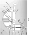
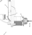
- FIGS. 2-3 are side views of an example apparatus in accordance with an embodiment of the invention.
- the apparatus as illustrated in FIG. 3 and generally designated by the reference numeral 50, is shown in an "open" position in which a liquid drop analyte or reference sample of less than about 10 ⁇ l, more often less than about 2 ⁇ l, is dispensed or aspirated onto a lower platform surface 15 (also referenced herein as the second pedestal surface).
- a liquid drop analyte or reference sample of less than about 10 ⁇ l, more often less than about 2 ⁇ l
- a lower platform surface 15 also referenced herein as the second pedestal surface
- such an "open" position enables easy access to the ends of the surfaces, e.g., surface 15, which contain the liquid samples and also enable a user to easily clean such surfaces and to mount a new sample within the apparatus when desired.
- the dispensing of a liquid sample of less than about 10 ⁇ l, often less than about 2 ⁇ l can often be delivered by way of a pipetting means (not shown), such as, but not limited to, a Finnpipette ® from Thermo Fisher Scientific of Waltham, Mass.
- the pipetted liquid is thus delivered to the lower platform 15, which is often configured as a pedestal or anvil-like surface that may include the end of a custom or commercial SMA fiber optic connector 16s, and of which, also may in some applications, be treated with a material known by those of ordinary skill in the art to prevent over spreading of the applied liquid drop analyte or reference sample (not shown).
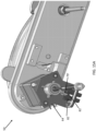
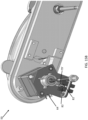
- the apparatus 50 is angularly moved by a user to be in the "closed” position, so as to result in the upper pedestal or anvil-like surface 13 (also referenced herein as the first pedestal surface), as specifically referenced in FIG. 3 , also often the end of a custom or commercial SMA fiber optic connector 12s, to be brought into contact with a dispensed liquid drop sample (not shown) to constrain a desired liquid drop sample therebetween with lower surface 15, also specifically referenced in FIG. 3 , in a surface tension mode at a variable distance (p) to pull the liquid sample into a column 9 (as shown in FIG. 1 ) so as to be contained by surface tension, or to squeeze the sample during optical analysis, thereby providing an optical path for photometric or spectrometric measurement.
- a dispensed liquid drop sample not shown
- lower surface 15 also specifically referenced in FIG. 3
- a surface tension mode at a variable distance (p) to pull the liquid sample into a column 9 (as shown in FIG. 1 ) so as to be
- the fiber optic connector 12s which contains surface 13, and of which is mounted within and passes through a bore in swing arm 54, also angularly rotates with respect to a base plate 52 about hinge rod 56 in order to come into contact with a liquid drop sample dispensed on surface 15.
- a mechanical stop 53 coupled to the base plate 52 provides a desired position against which the lower surface of the arm 54 abuts when the arm is rotated so as to provide for the contact and measurement of liquid drop sample.
- a pair of optical conduits such as, for example, an upper optical fiber 18 a (also referenced herein as the first optical conduit) and a lower optical fiber 18b (also referenced herein as the second optical conduit) and disposed within respective connectors, e.g., connectors 12s and 16s, enable optical communication by way of being diametrically opposed with one another in their operating position, i.e., the "closed position" illustrated in FIG. 2 .
- optical conduits e.g., optical fibers 18 a and 18 b
- the first optical conduit 18 a is the transmitting end 12t, with or without an optical fiber forming the first optical conduit 18 a
- the optical connector 16 a of the second optical conduit 18b is the receiving end 16r, with or without an optical fiber forming the second optical conduit 18b, with said transmitting end 12t of said first optical conduit 18 a and said receiving end 16r of said second optical conduit 18 b providing the optical path for photometric or spectrometric measurement.
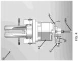
- the apparatus 60 as shown in FIG.
- the first optical conduit 18 a is the receiving end 12r, with or without an optical fiber forming the first optical conduit 18 a
- the optical connector 16 s of the second optical conduit 18 b is the transmitting end 16 t , with or without an optical fiber forming the second optical conduit 18 b , with said receiving end 12 r of said first optical conduit 18 a and said transmitting end 16 t of said second optical conduit 18 b providing the optical path for photometric or spectrometric measurement.
- the lower optical fiber holder 16s for the lower optical fiber 18b also serves as a shaft for a linear actuator, as described in greater detail below.
- the upper optical fiber connector 12 s (and consequently the coupled optical conduit fiber 18 a ) is fixed with respect to the swing arm 54, the lower optical fiber connector 16 s (and consequently the lower optical conduit, e.g., fiber 18 b ) may translate, parallel to its axis ( e.g ., along the vertical direction), so as to enable the spacing between the two optical fibers to be varied.
- the range of displacement of the lower optical fiber connector 16 s from the maximum to the minimum optical spacing between the two optical fibers is shown in FIGS. 14A and 14B , respectively.
- the base plate 52 is provided with a linear actuator that is mounted thereto so as provide for the precise translation of the lower optical fiber connector 16s.
- the linear actuator may include a motor 62 that is secured to the base plate 52 by means of fasteners 65 (such as, for instance, screws, posts, pins, rivets, etc. with or without associated bushings).
- the fasteners may also include extended motor mounting screws and may pass through bushings 68 which provide a slidable mechanical engagement with a plate or bracket 64, as further described below.
- the motor is designed to produce a rotational motion of a threaded nut (not shown) which bears on a mating threaded shaft portion (not shown) of the lower optical fiber holder 16s.
- the lower fiber optic connector 16s replaces and/or serves as the actuator shaft of the linear actuator.
- the rotation of the internally threaded screw against the externally threaded shaft portion, as driven in either direction by the motor 62, causes controlled translation of the lower fiber optic connector 16s and the disposed optical conduit, e.g., 18 b housed therein.
- the position of the lower fiber optic connector 16s is stabilized by a plate or bracket 64 which is mechanically coupled to the motor 62.
- the plate or bracket 64 may have holes or slots (not shown) through which the bushings 68 and the fasteners, such as screws 65, pass.
- the fasteners 65 may comprise extended motor mounting screws.
- the motor 62 may be further secured to the base plate 52 by additional fasteners (not shown).
- the motor 62 may be a commercially available motor or linear actuator or linear translator motor.
- a linear actuator motor assembly is available from Haydon Switch Instruments of Waterbury Conn. USA as part no. 28H43-05-036.
- the actuator shaft of a standard off-the-shelf linear actuator or linear translator apparatus may need to be replaced by the lower fiber optic holder 16s, as described herein.
- a position sensor 82 and opto-interrupter device 79' (also referenced herein as a "home flag") coupled to the second optical conduit 18b, which are used to establish a "home” position, are located beneath the lower pedestal surface where the optical path length is established and a measurement is made.
- the opto-interrupter device 79' is mechanically coupled to the lower optical fiber holder 16s (shown in FIG. 3 ) and translates linearly through the bracket 64.
- the displacement range of the opto-interrupter device 79' is shown in FIGS. 15A-B , and 16A-B , from a position above the "home” position, shown in FIGS. 15A and 16A , to the "home" position shown in FIGS.
- the system is capable of controlling the distance moved between two path lengths to within approximately 4 ⁇ m.
- the use of the differential absorbance method is not practical, as the allowable difference in the distance between path lengths becomes substantially shorter than the path lengths themselves.
- the allowable difference in the distance between path lengths decreases, even a relative positional accuracy of 4 ⁇ m becomes a substantial error.
- the apparatus for measuring an optical property of a sample includes - inter alia and as further defined with appended claim 1-a first pedestal surface coupled to i) a swing arm and to ii) a light source, a magnet, a base plate, a mechanical stop coupled to the base plate, and a second pedestal surface mechanically coupled to said base plate and configured to receive a liquid sample.
- the second pedestal surface is coupled to a spectrometer, wherein said second pedestal surface is further operable so as to adjust a separation between the first and the second pedestal surfaces at a variable distance (P) to pull the liquid sample into a column so as to be contained by surface tension, or to squeeze the sample during optical analysis, thereby providing an optical path for photometric or spectrometric measurement.
- the apparatus further includes a magnetic flux sensor located between north and south magnetic flux fields of the magnet such that the magnetic flux reaching the sensor while the mechanical stop is in physical contact with the swing arm provides a linear range of output of the magnetic flux sensor.
- the apparatus also includes a processor adapted to calibrate the point for minimum optical path length by utilizing a threshold magnetic flux field emitted from the magnet and detected by the magnetic flux sensor.
- the apparatus can further include a first optical conduit coupled to the first pedestal surface, a second optical conduit coupled to the second pedestal surface, and, optionally, a bracket configured to permit translational movement of said second optical conduit parallel to a longitudinal axis of said second optical conduit.
- a linear Hall effect sensor 10 is fixed to the base plate 52 and a magnet 1 is fixed to the swing arm 54. The magnet 1 is positioned such that the null plane of its north and south magnet flux fields is relatively centered on the linear Hall effect sensor 10.
- the linear Hall effect sensor 10 is positioned to detect a change in the magnetic flux field emitted from the magnet 1 as the swing arm 54 is lifted by the lower pedestal 15 first making contact with the upper pedestal 13. Post processing of the linear Hall effect sensor 10 readout is then used to establish an accurate position corresponding to zero path length.
- Alternative magnetic sensors to detect a change in the magnetic flux emitted from the magnet 1 include giant magnetoresistive (GMR) sensors that output a change in resistance in response to a change in magnetic flux field.
- GMR giant magnetoresistive
- the linear Hall effect sensor 10 is coupled to the swing arm 54, and the magnet 1 is coupled to the base plate 52.
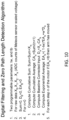
- the operation of the linear Hall effect sensor 10 is shown in FIG. 5 and described in the following steps:
- FIG. 7 A flowchart of zero path length detection is shown in FIG. 7 .
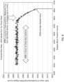
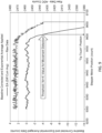
- An example of ADC values of conditioned linear Hall effect sensor signal and baseline corrected and exponential averaged data are shown in FIGS. 8 and 9 , respectively. It is apparent from the data shown in FIGS. 8 and 9 that the swing arm moves substantially before zero path length is triggered. This movement is necessary in order for the magnetic flux to change at the location of the linear Hall effect sensor. However, this displacement is tolerable as long as the arm displacement is reasonably close to the actual point where the mechanical stop was in physical contact with the swing arm, and the displacement is repeatable. To balance these requirements, "tb" was set to equal a value of -4, that is, four counts below the exponentially averaged baseline.
- the threshold magnetic flux field was equal to 0.012 mT at the linear Hall effect sensor.
- the exponential averaging weighing factor is 0.03 in the digital filtering and zero path length detection algorithm shown in FIG. 10 . As with the electronic filter shown in FIG. 5 , this digital filter coefficient was selected as a compromise between noise reduction and phase delay, while maintaining repeatability.
- a method of measuring an optical property of a sample includes - inter alia and as further defined with appended claim 14-coupling a first pedestal surface and a magnet to a swing arm and to a light source, and coupling a mechanical stop and a magnetic flux sensor to a base plate.
- the method further includes coupling a second pedestal surface to said base plate, the second pedestal surface configured to receive a liquid sample and further operable so as to adjust a separation between said first and said second pedestal surfaces at a variable distance (P) to pull said liquid sample into a column so as to be contained by surface tension, or to squeeze the sample during optical analysis, thereby providing an optical path for photometric or spectrometric measurement.
- P variable distance
- the method also includes locating the magnetic flux sensor between north and south magnetic flux fields of the magnet such that the magnetic flux reaching the sensor while the mechanical stop is in physical contact with the swing arm provides a linear range of output of the magnetic flux sensor, and utilizing a threshold magnetic flux field emitted from the magnet and detected by the magnetic flux sensor to calibrate the point for minimum optical path length.
- An exemplary zero path length detection method shown in FIG. 7 , includes the following steps:
- FIGS. 11A-C An embodiment of the path length calibration method is shown in FIGS. 11A-C .
- An exemplary initial path length calibration, as shown in FIG 11A includes the following steps:
- An exemplary implementation of zero path length includes the following steps:
- Another alternative is to eliminate the path length calibration process, which stores discrete stepper motor positions based on a reference position for each path length of interest, and rely on the zero path length position and pitch of the lead screw to determine the number of motor steps require to achieve any desired path length.
Landscapes
- Physics & Mathematics (AREA)
- General Physics & Mathematics (AREA)
- General Health & Medical Sciences (AREA)
- Analytical Chemistry (AREA)
- Pathology (AREA)
- Immunology (AREA)
- Biochemistry (AREA)
- Health & Medical Sciences (AREA)
- Life Sciences & Earth Sciences (AREA)
- Chemical & Material Sciences (AREA)
- Spectroscopy & Molecular Physics (AREA)
- Condensed Matter Physics & Semiconductors (AREA)
- Engineering & Computer Science (AREA)
- Theoretical Computer Science (AREA)
- Mathematical Physics (AREA)
- Investigating Or Analysing Materials By Optical Means (AREA)
- Investigating Or Analyzing Materials By The Use Of Magnetic Means (AREA)
- Optical Measuring Cells (AREA)
Claims (16)
- Einrichtung zum Messen einer optischen Eigenschaft einer Probe, die Einrichtung umfassend:a. einen Schwenkarm (54);b. eine Lichtquelle;c. eine erste Sockeloberfläche (13), die mit i) dem Schwenkarm (54) und ii) der Lichtquelle gekoppelt ist;d. einen Magneten (1);e. eine Grundplatte (52);f. einen mechanischen Anschlag (53), der mit der Grundplatte (52) gekoppelt ist;g. ein Spektrometer;h. eine zweite Sockeloberfläche (15), die mit der Grundplatte (52) mechanisch gekoppelt und konfiguriert ist, um eine Flüssigkeitsprobe zu empfangen, wobei die zweite Sockeloberfläche (15) mit dem Spektrometer gekoppelt ist, wobei die zweite Sockeloberfläche (15) ferner betriebsfähig ist, um eine Trennung zwischen der ersten und der zweiten Sockeloberfläche (13, 15) mit einem variablen Abstand (P) einzustellen, um die Flüssigkeitsprobe in eine Säule (9) zu ziehen, um durch Oberflächenspannung zurückgehalten zu werden, oder um die Probe während einer optischen Analyse zusammenzupressen, wobei dadurch ein optischer Weg für eine photometrische oder spektrometrische Messung bereitgestellt wird;i. einen Magnetflusssensor (10), der derart angeordnet ist, dass eine Nullebene von Nord- und Süd-Magnetflussfeldern des Magneten (1) auf dem Magnetflusssensor (10) zentriert ist, wobei der Magnetflusssensor (10) ferner positioniert ist, um eine Änderung des Magnetflussfelds zu erfassen, das von dem Magneten (1) emittiert wird, wenn der Schwenkarm (54) durch die zweite Sockeloberfläche (15) angehoben wird, die zuerst die erste Sockeloberfläche (13) berührt, und wobei der Magnet (1) mit dem Schwenkarm (54) gekoppelt ist und der Magnetflusssensor (10) mit der Grundplatte (52) gekoppelt ist, oder wobei der Magnetflusssensor (10) mit dem Schwenkarm (54) gekoppelt ist und der Magnet (1) mit der Grundplatte (52) gekoppelt ist; undj. einen Prozessor, der angepasst ist, um den Punkt für eine minimale Länge des optischen Wegs durch Nutzen eines Schwellenmagnetflussfelds zu kalibrieren, das von dem Magneten (1) emittiert und durch den Magnetflusssensor (10) erfasst wird;k. einen Mikroprozessor, der konfiguriert ist, um eine Offset-Spannung der Magnetflusssensorausgabe zu steuern; undl. einen Analog-Digital-Wandler, der konfiguriert ist, um die Offset-Magnetflusssensorausgabe zu digitalisieren.
- Einrichtung nach Anspruch 1, wobei die erste Sockeloberfläche (13) mit einer ersten optischen Leitung (18a) gekoppelt ist.
- Einrichtung nach Anspruch 2, wobei die zweite Sockeloberfläche (15) mit einer zweiten optischen Leitung (18b) gekoppelt ist.
- Einrichtung nach Anspruch 3, wobei die erste und die zweite optische Leitung (18a, 18b) mindestens eine Lichtleitfaser umfassen, die ausgewählt ist aus: einer Einzelmodusfaser, einer polarisationserhaltenden Faser und einer Mehrmodenfaser.
- Einrichtung nach Anspruch 3, die ferner eine Halterung (64) beinhaltet, die konfiguriert ist, um eine Translationsbewegung der zweiten optischen Leitung (18b) parallel zu einer Längsachse der zweiten optischen Leitung (18b) zuzulassen.
- Einrichtung nach Anspruch 5, wobei die Halterung (64) ferner einen Positionssensor (82) umfasst, der eine Rückmeldung bereitstellt, um eine Feinverschiebung zwischen der ersten und der zweiten Sockeloberfläche (13, 15) zu ermöglichen, um den variablen Abstand (P) zu ermöglichen.
- Einrichtung nach Anspruch 6, umfassend eine Opto-Unterbrechervorrichtung (79') und ein Translationssteuersystem, wobei der Positionssensor (82) ferner konfiguriert ist, um eine Referenzposition festzulegen, wenn das Translationssteuersystem bei einem Starten oder bei Unterbrechung durch die Opto-Unterbrechervorrichtung (79'), die mit der zweiten optischen Leitung (18b) gekoppelt ist, initialisiert wird.
- Einrichtung nach Anspruch 3, wobei die erste optische Leitung (18a) ein Übertragungsende (12t) beinhaltet und die zweite optische Leitung (18b) ein Empfangsende (12r) beinhaltet, wobei das Übertragungsende (12t) der ersten optischen Leitung (18a) und das Empfangsende (12r) der zweiten optischen Leitung (18b) den optischen Weg für die photometrische oder spektrometrische Messung bereitstellen.
- Einrichtung nach Anspruch 3, wobei die erste optische Leitung (18a) ein Empfangsende (12r) beinhaltet und die zweite optische Leitung (18b) ein Übertragungsende (12t) beinhaltet, wobei das Empfangsende (12r) der ersten optischen Leitung (18a) und das Übertragungsende (12t) der zweiten optischen Leitung (18b) den optischen Weg für die photometrische oder spektrometrische Messung bereitstellen.
- Einrichtung nach Anspruch 1, wobei der Magnetflusssensor (10) ein linearer Hall-Effekt-Sensor ist.
- Einrichtung nach Anspruch 1, wobei der Magnetflusssensor (10) ein Riesenmagnetowiderstands-Sensor, GMR-Sensor, ist.
- Einrichtung nach einem der vorstehenden Ansprüche, wobei die Einrichtung Extinktionen in einem Bereich von zwischen ungefähr 0,005 Extinktionseinheiten und ungefähr 2,0 Extinktionseinheiten für eine beliebige gegebene optische Weglänge misst.
- Einrichtung nach einem der vorstehenden Ansprüche, wobei die Lichtquelle konfiguriert ist, um optische Wellenlängen in einem Bereich von zwischen ungefähr 190 nm und ungefähr 850 nm bereitzustellen.
- Verfahren zum Messen einer optischen Eigenschaft einer Probe, das Verfahren umfassend:a. Koppeln einer ersten Sockeloberfläche (13) und eines Magneten (1) mit einem Schwenkarm (54) und mit einer Lichtquelle; oder Koppeln einer ersten Sockeloberfläche (13) und eines Magnetflusssensors (10) mit einem Schwenkarm (54) und mit einer Lichtquelle;b. Koppeln eines mechanischen Anschlags (53) und eines Magnetflusssensors (10) mit einer Grundplatte (52); oder Koppeln des mechanischen Stopps (53) und des Magneten (1) mit einer Grundplatte (52);c. Koppeln einer zweiten Sockeloberfläche (15) mit der Grundplatte (52), wobei die zweite Sockeloberfläche (15) konfiguriert ist, um eine Flüssigkeitsprobe zu empfangen, und ferner betriebsfähig ist, um eine Trennung zwischen der ersten und der zweiten Sockeloberfläche (13, 15) mit einem variablen Abstand (P) einzustellen, um die Flüssigkeitsprobe in eine Säule (9) zu ziehen, um durch Oberflächenspannung zurückgehalten zu werden, oder um die Probe während der optischen Analyse zusammenzupressen, wobei dadurch ein optischer Weg für die photometrische oder spektrometrische Messung bereitgestellt wird;d. Anordnen des Magnetflusssensors (10) derart, dass eine Nullebene der Nord- und Süd-Magnetflussfelder des Magneten (1) auf dem Magnetflusssensor (10) zentriert ist, wobei der Magnetflusssensor (10) ferner positioniert ist, um eine Änderung des Magnetflussfelds zu erfassen, das von dem Magneten (1) emittiert wird, wenn der Schwenkarm (54) durch die zweite Sockeloberfläche (15) angehoben wird, die zuerst die erste Sockeloberfläche (13) berührt, und wobei der Magnet (1) mit dem Schwenkarm (54) gekoppelt ist und der Magnetflusssensor (10) mit der Grundplatte (52) gekoppelt ist, oder wobei der Magnetflusssensor (10) mit dem Schwenkarm (54) gekoppelt ist und der Magnet (1) mit der Grundplatte (52) gekoppelt ist; unde. Nutzen eines Schwellenmagnetflussfelds, das von dem Magneten (1) emittiert und durch den Magnetflusssensor (10) erfasst wird, um den Punkt für die minimale optische Weglänge zu kalibrieren, wobei dieser Schritt umfasst:Anwenden eines Tiefpassfilters auf die Magnetflusssensorausgabe;Verstärken der gefilterten Magnetflusssensorausgabe;Anwenden einer Offset-Spannung auf die gefilterte verstärkte Magnetflusssensorausgabe;Digitalisieren der gefilterten verstärkten Offset-Magnetflusssensorausgabe.
- Verfahren nach Anspruch 14, wobei der Magnetflusssensor (10) ein linearer Hall-Effekt-Sensor ist.
- Verfahren nach Anspruch 14, wobei der Magnetflusssensor (10) ein Riesenmagnetowiderstands-Sensor, GMR-Sensor, ist.
Applications Claiming Priority (4)
| Application Number | Priority Date | Filing Date | Title |
|---|---|---|---|
| US201562220536P | 2015-09-18 | 2015-09-18 | |
| US201662306793P | 2016-03-11 | 2016-03-11 | |
| EP16770114.3A EP3350570B1 (de) | 2015-09-18 | 2016-08-25 | Pfadlängenkalibrierungssystem und -verfahren |
| PCT/US2016/048635 WO2017048475A1 (en) | 2015-09-18 | 2016-08-25 | Path length calibration system and method |
Related Parent Applications (2)
| Application Number | Title | Priority Date | Filing Date |
|---|---|---|---|
| EP16770114.3A Division-Into EP3350570B1 (de) | 2015-09-18 | 2016-08-25 | Pfadlängenkalibrierungssystem und -verfahren |
| EP16770114.3A Division EP3350570B1 (de) | 2015-09-18 | 2016-08-25 | Pfadlängenkalibrierungssystem und -verfahren |
Publications (2)
| Publication Number | Publication Date |
|---|---|
| EP3828526A1 EP3828526A1 (de) | 2021-06-02 |
| EP3828526B1 true EP3828526B1 (de) | 2023-11-01 |
Family
ID=56979635
Family Applications (2)
| Application Number | Title | Priority Date | Filing Date |
|---|---|---|---|
| EP20179928.5A Active EP3828526B1 (de) | 2015-09-18 | 2016-08-25 | Pfadlängenkalibrierungssystem und -verfahren |
| EP16770114.3A Active EP3350570B1 (de) | 2015-09-18 | 2016-08-25 | Pfadlängenkalibrierungssystem und -verfahren |
Family Applications After (1)
| Application Number | Title | Priority Date | Filing Date |
|---|---|---|---|
| EP16770114.3A Active EP3350570B1 (de) | 2015-09-18 | 2016-08-25 | Pfadlängenkalibrierungssystem und -verfahren |
Country Status (7)
| Country | Link |
|---|---|
| US (2) | US9952139B2 (de) |
| EP (2) | EP3828526B1 (de) |
| JP (2) | JP6778256B2 (de) |
| CN (1) | CN108139315B (de) |
| CA (1) | CA2995730C (de) |
| ES (2) | ES2967608T3 (de) |
| WO (1) | WO2017048475A1 (de) |
Families Citing this family (6)
| Publication number | Priority date | Publication date | Assignee | Title |
|---|---|---|---|---|
| CN108535673B (zh) * | 2018-04-13 | 2025-01-03 | 中国计量科学研究院 | 一种基于磁共振成像的光散射测量装置 |
| GB2580988B (en) * | 2019-03-19 | 2022-04-13 | Oxford Nanopore Tech Ltd | Current measurement apparatus, molecular entity sensing apparatus, method of measuring a current, method of sensing a molecular entity |
| KR102245238B1 (ko) * | 2019-10-29 | 2021-04-28 | (주)마이크로디지탈 | 흡광 분석 장치 |
| JP7487641B2 (ja) * | 2020-10-29 | 2024-05-21 | 株式会社デンソー | 電気機器 |
| CN115436282B (zh) * | 2022-08-09 | 2025-08-01 | 重庆凯奥科技发展有限公司 | 一种多光程超微量检测装置 |
| CN115727765B (zh) * | 2022-10-26 | 2026-03-06 | 无锡先导智能装备股份有限公司 | 一种双光纤电池纠偏方法及双光纤电池位置纠偏系统 |
Family Cites Families (16)
| Publication number | Priority date | Publication date | Assignee | Title |
|---|---|---|---|---|
| JPS63130772A (ja) * | 1986-11-20 | 1988-06-02 | Anelva Corp | 真空蒸着のモニタリング用センサ− |
| JPH02111272A (ja) * | 1988-10-19 | 1990-04-24 | Hitachi Electron Eng Co Ltd | 回転試料台の給電方式 |
| EP1210579B1 (de) | 1999-08-20 | 2008-06-04 | NanoDrop Technologies, LLC | Flüssigkeitsfotometer, das oberflächenspannung zur probenkontaktierung benutzt |
| US7183633B2 (en) * | 2001-03-01 | 2007-02-27 | Analog Devices Inc. | Optical cross-connect system |
| JP2002323345A (ja) * | 2001-04-25 | 2002-11-08 | Kayaba Ind Co Ltd | 回転角度センサ |
| US6661512B2 (en) * | 2002-02-13 | 2003-12-09 | Varian, Inc. | Sample analysis system with fiber optics and related method |
| US7088095B1 (en) * | 2004-02-04 | 2006-08-08 | Honeywell International Inc. | Balanced magnetic linear displacement sensor |
| JP2006284415A (ja) * | 2005-04-01 | 2006-10-19 | Nikon Corp | 位置検出装置およびカメラ |
| JP2006317191A (ja) * | 2005-05-10 | 2006-11-24 | Konica Minolta Opto Inc | 位置検出装置、電子機器 |
| EP2166313B1 (de) * | 2008-09-18 | 2011-11-09 | Sick Ag | Magnetischer Sensor |
| JP5567020B2 (ja) * | 2008-10-03 | 2014-08-06 | ナノドロップ テクノロジーズ リミテッド ライアビリティ カンパニー | 最適な吸光度測定のための光路長センサ及び方法 |
| JP5027191B2 (ja) * | 2009-07-31 | 2012-09-19 | 株式会社鷺宮製作所 | 圧力センサ及びその調整方法 |
| DE102011106523A1 (de) * | 2011-07-04 | 2013-01-10 | Giesecke & Devrient Gmbh | Prüfgerät und Verfahren zur Kalibrierung eines Prüfgeräts |
| GB2519460B (en) | 2012-07-09 | 2018-02-21 | Thermo Electron Scient Instruments Llc | Motorized variable path length cell for spectroscopy |
| JP5861898B2 (ja) * | 2013-06-04 | 2016-02-16 | 株式会社デンソー | 位置検出装置 |
| CN103759651B (zh) * | 2014-01-21 | 2016-05-25 | 沈阳师范大学 | 一种实时监控变温变压型激光散斑测量系统 |
-
2016
- 2016-08-25 WO PCT/US2016/048635 patent/WO2017048475A1/en not_active Ceased
- 2016-08-25 ES ES20179928T patent/ES2967608T3/es active Active
- 2016-08-25 CN CN201680049253.5A patent/CN108139315B/zh active Active
- 2016-08-25 JP JP2018513573A patent/JP6778256B2/ja active Active
- 2016-08-25 EP EP20179928.5A patent/EP3828526B1/de active Active
- 2016-08-25 CA CA2995730A patent/CA2995730C/en active Active
- 2016-08-25 EP EP16770114.3A patent/EP3350570B1/de active Active
- 2016-08-25 ES ES16770114T patent/ES2817533T3/es active Active
- 2016-09-12 US US15/262,171 patent/US9952139B2/en active Active
-
2018
- 2018-03-14 US US15/921,173 patent/US10481079B2/en active Active
-
2020
- 2020-10-09 JP JP2020170893A patent/JP6957713B2/ja active Active
Also Published As
| Publication number | Publication date |
|---|---|
| JP6778256B2 (ja) | 2020-10-28 |
| EP3350570A1 (de) | 2018-07-25 |
| CA2995730A1 (en) | 2017-03-23 |
| EP3350570B1 (de) | 2020-07-29 |
| EP3828526A1 (de) | 2021-06-02 |
| JP2021001913A (ja) | 2021-01-07 |
| ES2817533T3 (es) | 2021-04-07 |
| US10481079B2 (en) | 2019-11-19 |
| US20170082533A1 (en) | 2017-03-23 |
| ES2967608T3 (es) | 2024-05-03 |
| CN108139315A (zh) | 2018-06-08 |
| WO2017048475A1 (en) | 2017-03-23 |
| JP6957713B2 (ja) | 2021-11-02 |
| JP2018532108A (ja) | 2018-11-01 |
| US20180202919A1 (en) | 2018-07-19 |
| CN108139315B (zh) | 2021-03-05 |
| US9952139B2 (en) | 2018-04-24 |
| CA2995730C (en) | 2024-04-02 |
Similar Documents
| Publication | Publication Date | Title |
|---|---|---|
| US10481079B2 (en) | Path length calibration system and method | |
| CA2738904C (en) | Dual sample mode spectrophotometer | |
| EP0628157B1 (de) | Pipetteneichsystem | |
| US20160320252A1 (en) | Temperature Calibration for a Measuring Apparatus | |
| US8012766B2 (en) | Prediction of aspirated volume of a liquid | |
| EP0452403B1 (de) | Optisches spektrophotometer mit doppelter faser | |
| CA2880719C (en) | Apparatus and method to determine the blood sedimentation rate and other parameters connected thereto | |
| US20200333248A1 (en) | Optical analyzer | |
| JP2006003366A (ja) | 測定中におけるキュベットの安定化 | |
| KR101472504B1 (ko) | 시료 분석을 위한 광경로 자동조절 방법 및 이를 포함하는 시료 분석 방법과 그 장치. | |
| Kashyap et al. | Portable surface plasmon resonance (SPR) measurement device for sensing applications | |
| US20130070236A1 (en) | Method for determining the path length of a sample and validating the measurement obtained | |
| US7277167B2 (en) | Modular cuvettes and methods for use thereof | |
| Samuels et al. | Direct quantification of micro-thin-layer chromatograms | |
| CN115791645B (zh) | 一种新型的代谢类疾病检测方法 | |
| DE202016008012U1 (de) | System zur Weglängenkalibrierung | |
| JP2006300721A (ja) | 熱レンズ分光分析システム及び熱レンズ信号補正方法 |
Legal Events
| Date | Code | Title | Description |
|---|---|---|---|
| PUAI | Public reference made under article 153(3) epc to a published international application that has entered the european phase |
Free format text: ORIGINAL CODE: 0009012 |
|
| STAA | Information on the status of an ep patent application or granted ep patent |
Free format text: STATUS: THE APPLICATION HAS BEEN PUBLISHED |
|
| AC | Divisional application: reference to earlier application |
Ref document number: 3350570 Country of ref document: EP Kind code of ref document: P |
|
| AK | Designated contracting states |
Kind code of ref document: A1 Designated state(s): AL AT BE BG CH CY CZ DE DK EE ES FI FR GB GR HR HU IE IS IT LI LT LU LV MC MK MT NL NO PL PT RO RS SE SI SK SM TR |
|
| STAA | Information on the status of an ep patent application or granted ep patent |
Free format text: STATUS: REQUEST FOR EXAMINATION WAS MADE |
|
| 17P | Request for examination filed |
Effective date: 20211126 |
|
| RBV | Designated contracting states (corrected) |
Designated state(s): AL AT BE BG CH CY CZ DE DK EE ES FI FR GB GR HR HU IE IS IT LI LT LU LV MC MK MT NL NO PL PT RO RS SE SI SK SM TR |
|
| GRAP | Despatch of communication of intention to grant a patent |
Free format text: ORIGINAL CODE: EPIDOSNIGR1 |
|
| STAA | Information on the status of an ep patent application or granted ep patent |
Free format text: STATUS: GRANT OF PATENT IS INTENDED |
|
| RIC1 | Information provided on ipc code assigned before grant |
Ipc: G01D 5/14 20060101ALN20230427BHEP Ipc: G01N 21/31 20060101ALI20230427BHEP Ipc: G01D 5/00 20060101ALI20230427BHEP Ipc: G01N 21/03 20060101AFI20230427BHEP |
|
| RIC1 | Information provided on ipc code assigned before grant |
Ipc: G01D 5/14 20060101ALN20230504BHEP Ipc: G01N 21/31 20060101ALI20230504BHEP Ipc: G01N 21/03 20060101AFI20230504BHEP |
|
| INTG | Intention to grant announced |
Effective date: 20230522 |
|
| GRAS | Grant fee paid |
Free format text: ORIGINAL CODE: EPIDOSNIGR3 |
|
| GRAA | (expected) grant |
Free format text: ORIGINAL CODE: 0009210 |
|
| STAA | Information on the status of an ep patent application or granted ep patent |
Free format text: STATUS: THE PATENT HAS BEEN GRANTED |
|
| AC | Divisional application: reference to earlier application |
Ref document number: 3350570 Country of ref document: EP Kind code of ref document: P |
|
| AK | Designated contracting states |
Kind code of ref document: B1 Designated state(s): AL AT BE BG CH CY CZ DE DK EE ES FI FR GB GR HR HU IE IS IT LI LT LU LV MC MK MT NL NO PL PT RO RS SE SI SK SM TR |
|
| REG | Reference to a national code |
Ref country code: GB Ref legal event code: FG4D |
|
| REG | Reference to a national code |
Ref country code: CH Ref legal event code: EP |
|
| REG | Reference to a national code |
Ref country code: DE Ref legal event code: R096 Ref document number: 602016083942 Country of ref document: DE |
|
| REG | Reference to a national code |
Ref country code: IE Ref legal event code: FG4D |
|
| P01 | Opt-out of the competence of the unified patent court (upc) registered |
Effective date: 20231020 |
|
| REG | Reference to a national code |
Ref country code: LT Ref legal event code: MG9D |
|
| REG | Reference to a national code |
Ref country code: NL Ref legal event code: MP Effective date: 20231101 |
|
| PG25 | Lapsed in a contracting state [announced via postgrant information from national office to epo] |
Ref country code: GR Free format text: LAPSE BECAUSE OF FAILURE TO SUBMIT A TRANSLATION OF THE DESCRIPTION OR TO PAY THE FEE WITHIN THE PRESCRIBED TIME-LIMIT Effective date: 20240202 |
|
| PG25 | Lapsed in a contracting state [announced via postgrant information from national office to epo] |
Ref country code: IS Free format text: LAPSE BECAUSE OF FAILURE TO SUBMIT A TRANSLATION OF THE DESCRIPTION OR TO PAY THE FEE WITHIN THE PRESCRIBED TIME-LIMIT Effective date: 20240301 |
|
| PG25 | Lapsed in a contracting state [announced via postgrant information from national office to epo] |
Ref country code: LT Free format text: LAPSE BECAUSE OF FAILURE TO SUBMIT A TRANSLATION OF THE DESCRIPTION OR TO PAY THE FEE WITHIN THE PRESCRIBED TIME-LIMIT Effective date: 20231101 |
|
| REG | Reference to a national code |
Ref country code: AT Ref legal event code: MK05 Ref document number: 1627738 Country of ref document: AT Kind code of ref document: T Effective date: 20231101 |
|
| PG25 | Lapsed in a contracting state [announced via postgrant information from national office to epo] |
Ref country code: NL Free format text: LAPSE BECAUSE OF FAILURE TO SUBMIT A TRANSLATION OF THE DESCRIPTION OR TO PAY THE FEE WITHIN THE PRESCRIBED TIME-LIMIT Effective date: 20231101 |
|
| PG25 | Lapsed in a contracting state [announced via postgrant information from national office to epo] |
Ref country code: AT Free format text: LAPSE BECAUSE OF FAILURE TO SUBMIT A TRANSLATION OF THE DESCRIPTION OR TO PAY THE FEE WITHIN THE PRESCRIBED TIME-LIMIT Effective date: 20231101 |
|
| PG25 | Lapsed in a contracting state [announced via postgrant information from national office to epo] |
Ref country code: NL Free format text: LAPSE BECAUSE OF FAILURE TO SUBMIT A TRANSLATION OF THE DESCRIPTION OR TO PAY THE FEE WITHIN THE PRESCRIBED TIME-LIMIT Effective date: 20231101 Ref country code: LT Free format text: LAPSE BECAUSE OF FAILURE TO SUBMIT A TRANSLATION OF THE DESCRIPTION OR TO PAY THE FEE WITHIN THE PRESCRIBED TIME-LIMIT Effective date: 20231101 Ref country code: IS Free format text: LAPSE BECAUSE OF FAILURE TO SUBMIT A TRANSLATION OF THE DESCRIPTION OR TO PAY THE FEE WITHIN THE PRESCRIBED TIME-LIMIT Effective date: 20240301 Ref country code: GR Free format text: LAPSE BECAUSE OF FAILURE TO SUBMIT A TRANSLATION OF THE DESCRIPTION OR TO PAY THE FEE WITHIN THE PRESCRIBED TIME-LIMIT Effective date: 20240202 Ref country code: BG Free format text: LAPSE BECAUSE OF FAILURE TO SUBMIT A TRANSLATION OF THE DESCRIPTION OR TO PAY THE FEE WITHIN THE PRESCRIBED TIME-LIMIT Effective date: 20240201 Ref country code: AT Free format text: LAPSE BECAUSE OF FAILURE TO SUBMIT A TRANSLATION OF THE DESCRIPTION OR TO PAY THE FEE WITHIN THE PRESCRIBED TIME-LIMIT Effective date: 20231101 Ref country code: PT Free format text: LAPSE BECAUSE OF FAILURE TO SUBMIT A TRANSLATION OF THE DESCRIPTION OR TO PAY THE FEE WITHIN THE PRESCRIBED TIME-LIMIT Effective date: 20240301 |
|
| REG | Reference to a national code |
Ref country code: ES Ref legal event code: FG2A Ref document number: 2967608 Country of ref document: ES Kind code of ref document: T3 Effective date: 20240503 |
|
| PG25 | Lapsed in a contracting state [announced via postgrant information from national office to epo] |
Ref country code: SE Free format text: LAPSE BECAUSE OF FAILURE TO SUBMIT A TRANSLATION OF THE DESCRIPTION OR TO PAY THE FEE WITHIN THE PRESCRIBED TIME-LIMIT Effective date: 20231101 Ref country code: RS Free format text: LAPSE BECAUSE OF FAILURE TO SUBMIT A TRANSLATION OF THE DESCRIPTION OR TO PAY THE FEE WITHIN THE PRESCRIBED TIME-LIMIT Effective date: 20231101 Ref country code: PL Free format text: LAPSE BECAUSE OF FAILURE TO SUBMIT A TRANSLATION OF THE DESCRIPTION OR TO PAY THE FEE WITHIN THE PRESCRIBED TIME-LIMIT Effective date: 20231101 Ref country code: NO Free format text: LAPSE BECAUSE OF FAILURE TO SUBMIT A TRANSLATION OF THE DESCRIPTION OR TO PAY THE FEE WITHIN THE PRESCRIBED TIME-LIMIT Effective date: 20240201 Ref country code: LV Free format text: LAPSE BECAUSE OF FAILURE TO SUBMIT A TRANSLATION OF THE DESCRIPTION OR TO PAY THE FEE WITHIN THE PRESCRIBED TIME-LIMIT Effective date: 20231101 Ref country code: HR Free format text: LAPSE BECAUSE OF FAILURE TO SUBMIT A TRANSLATION OF THE DESCRIPTION OR TO PAY THE FEE WITHIN THE PRESCRIBED TIME-LIMIT Effective date: 20231101 |
|
| PG25 | Lapsed in a contracting state [announced via postgrant information from national office to epo] |
Ref country code: DK Free format text: LAPSE BECAUSE OF FAILURE TO SUBMIT A TRANSLATION OF THE DESCRIPTION OR TO PAY THE FEE WITHIN THE PRESCRIBED TIME-LIMIT Effective date: 20231101 |
|
| PG25 | Lapsed in a contracting state [announced via postgrant information from national office to epo] |
Ref country code: CZ Free format text: LAPSE BECAUSE OF FAILURE TO SUBMIT A TRANSLATION OF THE DESCRIPTION OR TO PAY THE FEE WITHIN THE PRESCRIBED TIME-LIMIT Effective date: 20231101 |
|
| PG25 | Lapsed in a contracting state [announced via postgrant information from national office to epo] |
Ref country code: SK Free format text: LAPSE BECAUSE OF FAILURE TO SUBMIT A TRANSLATION OF THE DESCRIPTION OR TO PAY THE FEE WITHIN THE PRESCRIBED TIME-LIMIT Effective date: 20231101 |
|
| PG25 | Lapsed in a contracting state [announced via postgrant information from national office to epo] |
Ref country code: SM Free format text: LAPSE BECAUSE OF FAILURE TO SUBMIT A TRANSLATION OF THE DESCRIPTION OR TO PAY THE FEE WITHIN THE PRESCRIBED TIME-LIMIT Effective date: 20231101 Ref country code: SK Free format text: LAPSE BECAUSE OF FAILURE TO SUBMIT A TRANSLATION OF THE DESCRIPTION OR TO PAY THE FEE WITHIN THE PRESCRIBED TIME-LIMIT Effective date: 20231101 Ref country code: IT Free format text: LAPSE BECAUSE OF FAILURE TO SUBMIT A TRANSLATION OF THE DESCRIPTION OR TO PAY THE FEE WITHIN THE PRESCRIBED TIME-LIMIT Effective date: 20231101 Ref country code: EE Free format text: LAPSE BECAUSE OF FAILURE TO SUBMIT A TRANSLATION OF THE DESCRIPTION OR TO PAY THE FEE WITHIN THE PRESCRIBED TIME-LIMIT Effective date: 20231101 Ref country code: DK Free format text: LAPSE BECAUSE OF FAILURE TO SUBMIT A TRANSLATION OF THE DESCRIPTION OR TO PAY THE FEE WITHIN THE PRESCRIBED TIME-LIMIT Effective date: 20231101 Ref country code: CZ Free format text: LAPSE BECAUSE OF FAILURE TO SUBMIT A TRANSLATION OF THE DESCRIPTION OR TO PAY THE FEE WITHIN THE PRESCRIBED TIME-LIMIT Effective date: 20231101 |
|
| REG | Reference to a national code |
Ref country code: DE Ref legal event code: R097 Ref document number: 602016083942 Country of ref document: DE |
|
| PLBE | No opposition filed within time limit |
Free format text: ORIGINAL CODE: 0009261 |
|
| STAA | Information on the status of an ep patent application or granted ep patent |
Free format text: STATUS: NO OPPOSITION FILED WITHIN TIME LIMIT |
|
| 26N | No opposition filed |
Effective date: 20240802 |
|
| PG25 | Lapsed in a contracting state [announced via postgrant information from national office to epo] |
Ref country code: SI Free format text: LAPSE BECAUSE OF FAILURE TO SUBMIT A TRANSLATION OF THE DESCRIPTION OR TO PAY THE FEE WITHIN THE PRESCRIBED TIME-LIMIT Effective date: 20231101 |
|
| PG25 | Lapsed in a contracting state [announced via postgrant information from national office to epo] |
Ref country code: SI Free format text: LAPSE BECAUSE OF FAILURE TO SUBMIT A TRANSLATION OF THE DESCRIPTION OR TO PAY THE FEE WITHIN THE PRESCRIBED TIME-LIMIT Effective date: 20231101 |
|
| REG | Reference to a national code |
Ref country code: CH Ref legal event code: PL |
|
| PG25 | Lapsed in a contracting state [announced via postgrant information from national office to epo] |
Ref country code: LU Free format text: LAPSE BECAUSE OF NON-PAYMENT OF DUE FEES Effective date: 20240825 |
|
| PG25 | Lapsed in a contracting state [announced via postgrant information from national office to epo] |
Ref country code: MC Free format text: LAPSE BECAUSE OF FAILURE TO SUBMIT A TRANSLATION OF THE DESCRIPTION OR TO PAY THE FEE WITHIN THE PRESCRIBED TIME-LIMIT Effective date: 20231101 Ref country code: CH Free format text: LAPSE BECAUSE OF NON-PAYMENT OF DUE FEES Effective date: 20240831 |
|
| REG | Reference to a national code |
Ref country code: BE Ref legal event code: MM Effective date: 20240831 |
|
| PG25 | Lapsed in a contracting state [announced via postgrant information from national office to epo] |
Ref country code: BE Free format text: LAPSE BECAUSE OF NON-PAYMENT OF DUE FEES Effective date: 20240831 |
|
| PG25 | Lapsed in a contracting state [announced via postgrant information from national office to epo] |
Ref country code: IE Free format text: LAPSE BECAUSE OF NON-PAYMENT OF DUE FEES Effective date: 20240825 |
|
| PG25 | Lapsed in a contracting state [announced via postgrant information from national office to epo] |
Ref country code: FI Free format text: LAPSE BECAUSE OF FAILURE TO SUBMIT A TRANSLATION OF THE DESCRIPTION OR TO PAY THE FEE WITHIN THE PRESCRIBED TIME-LIMIT Effective date: 20231101 |
|
| PGFP | Annual fee paid to national office [announced via postgrant information from national office to epo] |
Ref country code: ES Payment date: 20250911 Year of fee payment: 10 |
|
| PGFP | Annual fee paid to national office [announced via postgrant information from national office to epo] |
Ref country code: DE Payment date: 20250714 Year of fee payment: 10 |
|
| PGFP | Annual fee paid to national office [announced via postgrant information from national office to epo] |
Ref country code: GB Payment date: 20250811 Year of fee payment: 10 |
|
| PGFP | Annual fee paid to national office [announced via postgrant information from national office to epo] |
Ref country code: FR Payment date: 20250808 Year of fee payment: 10 |
|
| PG25 | Lapsed in a contracting state [announced via postgrant information from national office to epo] |
Ref country code: RO Free format text: LAPSE BECAUSE OF FAILURE TO SUBMIT A TRANSLATION OF THE DESCRIPTION OR TO PAY THE FEE WITHIN THE PRESCRIBED TIME-LIMIT Effective date: 20231101 |
|
| PG25 | Lapsed in a contracting state [announced via postgrant information from national office to epo] |
Ref country code: CY Free format text: LAPSE BECAUSE OF FAILURE TO SUBMIT A TRANSLATION OF THE DESCRIPTION OR TO PAY THE FEE WITHIN THE PRESCRIBED TIME-LIMIT; INVALID AB INITIO Effective date: 20160825 |
|
| PG25 | Lapsed in a contracting state [announced via postgrant information from national office to epo] |
Ref country code: HU Free format text: LAPSE BECAUSE OF FAILURE TO SUBMIT A TRANSLATION OF THE DESCRIPTION OR TO PAY THE FEE WITHIN THE PRESCRIBED TIME-LIMIT; INVALID AB INITIO Effective date: 20160825 |