EP3828575A2 - Système d'imagerie par résonance magnétique doté d'un aimant rotatif - Google Patents
Système d'imagerie par résonance magnétique doté d'un aimant rotatif Download PDFInfo
- Publication number
- EP3828575A2 EP3828575A2 EP20202953.4A EP20202953A EP3828575A2 EP 3828575 A2 EP3828575 A2 EP 3828575A2 EP 20202953 A EP20202953 A EP 20202953A EP 3828575 A2 EP3828575 A2 EP 3828575A2
- Authority
- EP
- European Patent Office
- Prior art keywords
- magnet
- magnetic resonance
- magnetic field
- magnetic
- resonance imaging
- Prior art date
- Legal status (The legal status is an assumption and is not a legal conclusion. Google has not performed a legal analysis and makes no representation as to the accuracy of the status listed.)
- Granted
Links
Images





Classifications
-
- A—HUMAN NECESSITIES
- A61—MEDICAL OR VETERINARY SCIENCE; HYGIENE
- A61B—DIAGNOSIS; SURGERY; IDENTIFICATION
- A61B5/00—Measuring for diagnostic purposes; Identification of persons
- A61B5/45—For evaluating or diagnosing the musculoskeletal system or teeth
- A61B5/4538—Evaluating a particular part of the muscoloskeletal system or a particular medical condition
- A61B5/4542—Evaluating the mouth, e.g. the jaw
- A61B5/4547—Evaluating teeth
-
- A—HUMAN NECESSITIES
- A61—MEDICAL OR VETERINARY SCIENCE; HYGIENE
- A61B—DIAGNOSIS; SURGERY; IDENTIFICATION
- A61B5/00—Measuring for diagnostic purposes; Identification of persons
- A61B5/05—Detecting, measuring or recording for diagnosis by means of electric currents or magnetic fields; Measuring using microwaves or radio waves
- A61B5/055—Detecting, measuring or recording for diagnosis by means of electric currents or magnetic fields; Measuring using microwaves or radio waves involving electronic [EMR] or nuclear [NMR] magnetic resonance, e.g. magnetic resonance imaging
-
- G—PHYSICS
- G01—MEASURING; TESTING
- G01R—MEASURING ELECTRIC VARIABLES; MEASURING MAGNETIC VARIABLES
- G01R33/00—Arrangements or instruments for measuring magnetic variables
- G01R33/20—Arrangements or instruments for measuring magnetic variables involving magnetic resonance
- G01R33/28—Details of apparatus provided for in groups G01R33/44 - G01R33/64
- G01R33/32—Excitation or detection systems, e.g. using radio frequency signals
- G01R33/34—Constructional details, e.g. resonators, specially adapted to MR
- G01R33/34084—Constructional details, e.g. resonators, specially adapted to MR implantable coils or coils being geometrically adaptable to the sample, e.g. flexible coils or coils comprising mutually movable parts
-
- G—PHYSICS
- G01—MEASURING; TESTING
- G01R—MEASURING ELECTRIC VARIABLES; MEASURING MAGNETIC VARIABLES
- G01R33/00—Arrangements or instruments for measuring magnetic variables
- G01R33/20—Arrangements or instruments for measuring magnetic variables involving magnetic resonance
- G01R33/28—Details of apparatus provided for in groups G01R33/44 - G01R33/64
- G01R33/38—Systems for generation, homogenisation or stabilisation of the main or gradient magnetic field
- G01R33/3802—Manufacture or installation of magnet assemblies; Additional hardware for transportation or installation of the magnet assembly or for providing mechanical support to components of the magnet assembly
-
- G—PHYSICS
- G01—MEASURING; TESTING
- G01R—MEASURING ELECTRIC VARIABLES; MEASURING MAGNETIC VARIABLES
- G01R33/00—Arrangements or instruments for measuring magnetic variables
- G01R33/20—Arrangements or instruments for measuring magnetic variables involving magnetic resonance
- G01R33/28—Details of apparatus provided for in groups G01R33/44 - G01R33/64
- G01R33/38—Systems for generation, homogenisation or stabilisation of the main or gradient magnetic field
- G01R33/385—Systems for generation, homogenisation or stabilisation of the main or gradient magnetic field using gradient magnetic field coils
- G01R33/3858—Manufacture and installation of gradient coils, means for providing mechanical support to parts of the gradient-coil assembly
-
- G—PHYSICS
- G01—MEASURING; TESTING
- G01R—MEASURING ELECTRIC VARIABLES; MEASURING MAGNETIC VARIABLES
- G01R33/00—Arrangements or instruments for measuring magnetic variables
- G01R33/20—Arrangements or instruments for measuring magnetic variables involving magnetic resonance
- G01R33/28—Details of apparatus provided for in groups G01R33/44 - G01R33/64
- G01R33/38—Systems for generation, homogenisation or stabilisation of the main or gradient magnetic field
- G01R33/3808—Magnet assemblies for single-sided MR wherein the magnet assembly is located on one side of a subject only; Magnet assemblies for inside-out MR, e.g. for MR in a borehole or in a blood vessel, or magnet assemblies for fringe-field MR
-
- G—PHYSICS
- G01—MEASURING; TESTING
- G01R—MEASURING ELECTRIC VARIABLES; MEASURING MAGNETIC VARIABLES
- G01R33/00—Arrangements or instruments for measuring magnetic variables
- G01R33/20—Arrangements or instruments for measuring magnetic variables involving magnetic resonance
- G01R33/44—Arrangements or instruments for measuring magnetic variables involving magnetic resonance using nuclear magnetic resonance [NMR]
- G01R33/445—MR involving a non-standard magnetic field B0, e.g. of low magnitude as in the earth's magnetic field or in nanoTesla spectroscopy, comprising a polarizing magnetic field for pre-polarisation, B0 with a temporal variation of its magnitude or direction such as field cycling of B0 or rotation of the direction of B0, or spatially inhomogeneous B0 like in fringe-field MR or in stray-field imaging
Definitions
- X-ray-based imaging methods For this purpose, conventional or digital X-ray projection methods, and recently also three-dimensional X-ray methods, are used.
- An example of a three-dimensional X-ray method is digital volume tomography, which can be used for imaging of the teeth and the viscerocranium.
- Magnetic resonance tomography is an imaging method that avoids ionizing radiation. Furthermore, magnetic resonance tomography typically provides an enhanced soft tissue contrast in comparison to X-ray-based imaging methods and natively supports three-dimensional imaging of an examination object. Thus, magnetic resonance tomography represents a potential alternative to known X-ray methods for imaging teeth and/or jaws of the examination object as well as diagnosing dental diseases.
- Magnetic resonance tomography represents a prominent imaging method for acquiring images of an interior of the examination object.
- the examination object is positioned in a strong and homogeneous static magnetic field (B0 field) of a magnetic resonance device.
- the static magnetic field may comprise magnetic field strengths of 0.2 Tesla to 7 Tesla in order to align nuclear spins of the examination object along the static magnetic field.
- radiofrequency excitation pulses are emitted into the examination subject. Each radiofrequency excitation pulse causes a magnetization of nuclear spins within the examination object to deviate from the static magnetic field by an amount which is known as the flip angle.
- a radiofrequency excitation pulse may comprise an alternating magnetic field with a frequency which corresponds to the Larmor frequency at the respective static magnetic field strength.
- Excited nuclear spins may exhibit a rotating and decaying magnetization (nuclear magnetic resonance), which can be detected using dedicated radiofrequency antennas.
- rapidly switched magnetic gradient fields are superimposed on the static magnetic field.
- the received nuclear magnetic resonances are typically digitized and stored as complex values in a k-space matrix.
- This k-space matrix can be used as a basis for the reconstruction of magnetic resonance images and for determining spectroscopic data.
- a magnetic resonance image is typically reconstructed by means of a multi-dimensional Fourier transformation of the k-space matrix.
- magnetic resonance tomography is particularly suitable for continuous or repetitious diagnostic monitoring of dental diseases and/or tooth development, for example within the framework of a longitudinal imaging study.
- Longitudinal imaging studies may comprise carrying out a plurality of imaging examinations in order to determine a progression of a disease or a success of a therapeutic treatment over a predetermined period of time.
- Disadvantages usually associated with magnetic resonance tomography are an extensive space requirement and high equipment costs. These downsides may impede utilization of magnetic resonance tomography for dental imaging applications and the advantages associated with it.
- the inventive magnetic resonance imaging system comprises a magnetic field generation unit, an image acquisition region and a radiofrequency system including at least one radiofrequency antenna, wherein the radiofrequency system is configured to emit a radiofrequency excitation pulse into the image acquisition region and receive magnetic resonance signals from the image acquisition region.
- the magnetic field generation unit comprises at least one magnet configured to generate a magnetic field in the image acquisition region, a magnet holder configured to carry the at least one magnet and a rotation system configured to position the magnet holder along a rotation trajectory.
- the magnetic resonance imaging system may comprise a housing in which the rotation system, the magnet holder and the at least one magnet may be positioned in.
- the housing may comprise a transparent, a semi-transparent or an opaque material. It is conceivable, that the magnetic resonance imaging system and/or the housing comprise a protective cover positioned in a space between the rotation system and a surface of an examination object.
- the protective cover may be configured to protect the examination object from moving parts of the rotation system, such as the magnet holder and/or the at least one magnet.
- the examination object may be a body of a patient and/or a body region of the patient.
- the housing further comprises an electric conductor configured to shield the image acquisition region from electromagnetic interference.
- the magnetic resonance system may comprise a support structure configured to adjust a position and/or an orientation of the magnetic field generation unit and/or to align the at least one magnet with an imaging region of the examination object.
- An imaging region may be a diagnostically relevant volume of the patient, for example a volume comprising a heart, an eye, a tooth, multiple teeth, a dental arch or other (parts of) organs.
- the support structure may comprise an adjustment mechanism, such as a swivel joint, a rotating joint or the like, to adjust an orientation of the magnetic field generation unit with respect to the examination object.
- the support structure may comprise a telescope system and/or a rail system to adjust a height and/or a distance of the magnetic field generation unit with respect to the examination object.
- the support structure and/or the adjustment mechanism may provide for at least two degrees of motion, at least three degrees of motion, at least four degrees of motion or at least five degrees of motion of the magnetic field generation unit.
- the image acquisition region may represent a volume wherein the examination object is positioned in order to perform a magnetic resonance imaging examination of the examination object.
- the image acquisition region typically is at least partially encompassed by the magnetic field generation unit.
- the image acquisition region may be confined by the magnetic field generation unit in at least one spatial direction, at least two spatial directions or at least three spatial directions. It is also conceivable, that the image acquisition region is encompassed by the magnetic field generation unit in a circumferential direction.
- the magnetic resonance imaging system may comprise an opening configured to provide an entry to the image acquisition region.
- the opening may comprise any shape or geometry suitable for receiving an examination object.
- the housing comprises an opening, such as a circular hole or an oval hole, in order to provide access of the body and/or the body region of the patient to the image acquisition region.
- the rotation system may comprise an arc-shaped element.
- An outline of the arc-shaped element may correspond to at least a section of a perimeter of a circle or an oval.
- the rotation system may further comprise a rotation center which may represent a center of a circle or oval circumscribing the outline of the arc-shaped element.
- the rotation trajectory may extend along at least a section of the arc-shaped element of the rotation system. It is conceivable, that the opening of the magnetic resonance imaging system is provided by an opening in the arc-shaped element of the rotation system, thus enabling the examination object to enter the image acquisition region.
- a motion of the magnet holder carrying the at least one magnet along the rotation trajectory may result in a relative motion between the magnetic field generated by the at least one magnet and the rotation center.
- the rotation system comprises a motor configured to position the magnet holder along the rotation trajectory.
- the motor may comprise any kind of drive system, for example an electric, a hydraulic and/or a pneumatic actuator, configured to move the magnet holder along the rotation trajectory.
- the motor of the rotation system is configured to move the magnet holder along the rotation trajectory in a continuous fashion.
- the motor may also be configured to move the magnet holder in a step-by-step fashion, e. g.
- the motion of the magnet holder along the rotation trajectory may cause a corresponding motion of the magnetic field within the image acquisition region of the magnetic resonance imaging device.
- the magnet holder may be any kind of structure configured to carry the at least one magnet.
- the at least one magnet is reversibly mounted on the magnet holder via any kind of locking and/or frictional connection.
- the connection between the at least one magnet and the magnet holder may be realized via a fastener mechanically joining the magnet holder and the at least one magnet.
- the at least one magnet may also be materially bonded to the magnet holder, for example via use of an adhesive.
- the at least one magnet of the magnetic field generation unit may be configured to provide a static magnetic field in the image acquisition region over a predetermined time period.
- the magnetic field provided by the at least one magnet may be constant over a time period of a few milliseconds to a few seconds.
- the magnetic field provided by the at least one magnet may be constant over a time period of several days, several months or several years.
- the static magnetic field provided by the at least one magnet is typically defined as the B0 magnetic field.
- the magnetic resonance imaging system is configured to acquire magnetic resonance imaging data from an examination object positioned in the image acquisition region.
- the magnetic resonance imaging system may comprise further components usually required for performing a magnetic resonance imaging examination and for processing acquired magnetic resonance imaging data.
- the magnetic resonance imaging system may comprise a processing unit which may be configured to reconstruct a magnetic resonance image from magnetic resonance signals acquired from the image acquisition region.
- the magnetic field generation unit comprises a permanent magnet.
- the at least one magnet may be a permanent magnet.
- the use of a permanent magnet may favorably avoid costs and space required for cooling equipment usually associated with superconducting magnets and electromagnets.
- the permanent magnet may consist of any suitable magnetic material such as AlNiCo (aluminum-nickel-cobalt), NeFeB (neodymium-iron-boron), or SmCo (samarium-cobalt) alloys.
- the permanent magnet may comprise any desired shape.
- the permanent magnet comprises a bar shape.
- a bar shape may include a cuboid bar shape, a cylindrical bar shape or a bar shape with a polygonal cross-section, such as a prism.
- Bar-shaped permanent magnets provide a low-cost solution for generating a magnetic field within the image acquisition region.
- bar-shaped permanent magnets may favorably be oriented in a direction of the examination object while moving the at least one magnet along the rotation trajectory of the rotation system.
- the permanent magnet comprises a C-shaped form and two magnetic poles positioned at two opposing ends of the C-shaped form.
- a C-shaped permanent magnet may favorably increase the magnetic field homogeneity in a region close to the two magnetic poles of the at least one permanent magnet.
- the magnetic field generation unit comprises an electromagnet.
- the at least one magnet may be an electromagnet.
- the electromagnet may comprise an electrical conductor wound around a magnetic core made of, for example, a ferromagnetic or ferrimagnetic material.
- the magnetic core of the electromagnet may comprise a cylindrical shape, a C-shape, a cuboid shape or any other desirable shape.
- the magnetic field generated by the at least one magnet projects from a face of the poles of the at least one magnet in such way that an imaging volume provided by the at least one magnet is situated in front of the face of the poles.
- An imaging volume may be positioned inside the image acquisition region of the magnetic resonance imaging device and may be moved with respect to the rotation center, when the magnet holder is moved along the rotation trajectory.
- the imaging volume may be characterized by a particularly homogenous magnetic field. However, it is also conceivable, that the imaging volume is characterized by an approximately linear magnetic field gradient.
- a size of the imaging volume may coincide with a size of the magnetic field provided by the at least one magnet. However, the size of the imaging volume may also be significantly smaller than the size of the magnetic field.
- the at least one magnet is oriented in such a way, that the imaging volume overlaps with at least a part of the imaging region comprising a diagnostically relevant area or volume within the examination object.
- the imaging volume may be positioned in proximity to a face of the pole of the at least one magnet oriented approximately in the direction of the rotation center.
- a distance between the imaging volume and the face of the pole oriented in the direction of the rotation center may be less than 5 cm, less than 4 cm or preferably less than 3 cm.
- the imaging volume can advantageously be moved along a diagnostically relevant volume of the examination object.
- costs and/or spatial requirements associated with stronger magnets capable of providing an imaging volume in a greater distance to the at least one magnet can favorably be avoided.
- the magnetic field generated by the at least one magnet comprises a magnetic field strength in the range of 0.01 to 1.5 Tesla, preferably in the range of 0.3 to 1.0 Tesla.
- the at least one magnet is configured to generate a substantially homogeneous magnetic field in the image acquisition region.
- a volume within the image acquisition region, wherein the magnetic field is particularly homogenous may be an isocenter.
- the isocenter may represent at least a part of the imaging volume. However, the isocenter may also coincide with the imaging volume.
- a shape of the isocenter may be represented by a sphere, an ovoid, a cuboid, a prism, a star or any combination of these shapes. It is conceivable, that a diameter of a sphere with the same volume as the isocenter may range between 0.5 cm and 5 cm, 5 cm and 10 cm, 10 cm and 15 cm or 15 cm and 20 cm.
- the diameter of a sphere with the same volume as the isocenter is smaller than 4 cm.
- the isocenter may be positioned anywhere in the image acquisition region. However, in a preferred embodiment, the isocenter is positioned in close proximity to a pole face of the at least one magnet as descried above.
- the magnetic field generated by the at least one magnet may be configured in such way, that two arbitrarily chosen points in the isocenter differ in magnetic field strength by less than 1 ppm (part per million), less than 5 ppm, less than 10 ppm, less than 15 ppm or less than 20 ppm.
- the at least one magnet may comprise any shape or geometry required for providing the substantially homogeneous magnetic field in the image acquisition region. The provision of the substantially homogeneous magnetic field may advantageously increase a quality of magnetic resonance images provided by the magnetic resonance system.
- the at least one magnet is configured to generate an inhomogeneous magnetic field in the image acquisition region, wherein the inhomogeneous magnetic field comprises a magnetic field gradient along a radial direction of the rotation trajectory.
- a radial direction may be characterized by a vector extending from an arbitrary point on the rotation trajectory to the rotation center of the rotation system. It is conceivable, that the magnetic field strength of the magnetic field provided by the at least one magnet decreases in a direction towards to the rotation center. For example, the strength of the magnetic field may decrease in a linear fashion, a hyperbolic fashion, an exponential fashion or in any other fashion.
- the vector may also be divided into segments, each characterized by an approximately linearly, hyperbolically or exponentially decreasing magnetic field strength.
- the inhomogeneous magnetic field of the at least one magnet may represent a known characteristic of the at least on magnet, which may be taken into account during acquisition of magnetic resonance signals, spatial encoding of magnetic resonance signals and/or reconstruction of magnetic resonance images.
- the processing unit of the magnetic resonance imaging system is configured to perform a spatial encoding of magnetic resonance signals acquired from the image acquisition region in dependence of the magnetic field gradient along the radial direction of the rotation trajectory.
- a slice of an imaging volume provided by the at least one magnet within the image acquisition region may be excited via a selective radiofrequency excitation pulse provided by the radiofrequency antenna.
- the selective radiofrequency excitation pulse may comprise a frequency corresponding to a Larmor frequency of a subset of nuclear spins within the magnetic gradient field gradient.
- magnetic resonance signals acquired from the excited slice may be assigned to specific locations between the at least one magnet and the rotation center.
- an inhomogeneous magnetic field may replace at least one magnetic field gradient of a magnetic field gradient system commonly employed to provide a means for spatial encoding of magnetic resonance signals from an imaging volume.
- costs and spatial requirements can be reduced in comparison to conventional magnetic resonance imaging system.
- the rotation system comprises a mechanical guiding rail which is configured to guide the magnet holder along the rotation trajectory around the rotation center.
- the mechanical guiding rail may be positioned on the arc-shaped element of the rotation system.
- a shape and/or a curvature of the mechanical guiding rail may correspond to a shape and/or curvature of the rotation trajectory.
- the mechanical guiding rail comprises a profile, such as a C-profile or a T-profile, which is configured to interlock with a carrier element carrying the magnet holder.
- the mechanical guiding rail may also comprise a simple bar, providing an edge or a ridge which may be at least partially encompassed by the carrier element.
- the carrier element may be guided along the rotation trajectory via the mechanical guiding rail.
- the carrier element and/or the mechanical guiding rail comprise bearings, such as ball bearings, in order to reduce friction between the carrier element and the mechanical guiding rail.
- the rotation system preferably comprises a motor configured to move the carrier element and the magnet holder on the mechanical guiding rail along the rotation trajectory.
- the mechanical guiding rail may limit the motion of the magnet holder to a line along rotation trajectory.
- the rotation trajectory comprises a rotation angle in the range of 120° to 270°, preferably in the range of 90° to 240°.
- the rotation angle may define how much of a circumference of the examination object is encompassed by the rotation system.
- imaging applications as for example imaging of an eye region, a jaw region or a breast region of a patient, it would just be required to move the at least one magnet along one side of the examination object in order to acquire magnetic resonance signals from these regions.
- it may be relevant to also image the regions from the sides in order to enhance coverage of these regions via the imaging volume.
- the rotation trajectory of the magnet holder may encompass the patient by more than 180°.
- the rotation angle is lower than 270°.
- a missing section of the circumference of the rotation trajectory may correspond to the opening which enables the patient to access the image acquisition volume.
- the examination object may be turned or rotated inside the image acquisition volume either continuously or in discrete steps to acquire magnetic resonance signals from an entire circumferential volume of the patient. Reducing the extent of the rotation trajectory may reduce a size of the rotation system, thus decreasing costs and/or spatial requirements of the magnetic resonance imaging system.
- providing a half-open rotation system encompassing a rotation angle in the range of approximately 90° to 240° instead of a full circle may advantageously facilitate access of a patient to the image acquisition region of the magnetic resonance system.
- the magnetic field generation unit comprises a first magnet and a second magnet, wherein the first magnet is configured to generate a first magnetic field inside the image acquisition region and the second magnet is configured to generate a second magnetic field inside the image acquisition region.
- the second magnet may be carried by a second magnet holder.
- a relative position of the second magnet holder and the first magnet holder is constant.
- the first magnet holder and the second magnet holder are mounted on a first carrier element of the mechanical guiding rail.
- the second magnet holder may also be mounted on a second carrier element of the mechanical guiding rail. It is conceivable, that the second carrier element comprises a spacing element which is connected to the first carrier element in order to ensure a constant distance between
- the first magnetic field may comprise a first imaging volume and the second magnetic field may comprise a second imaging volume.
- the first imaging volume may be spatially separated from the second imaging volume in such a way, that any intersection or overlap between the first imaging volume and the second imaging is avoided.
- a total imaging volume of the magnetic resonance system may be increased.
- the magnetic field generation unit comprises a third magnet, a fourth magnet or a plurality of further magnets, which are configured in a similar way.
- a subset of the first imaging volume overlaps with a subset of the second imaging volume.
- the first imaging volume corresponds to the second imaging volume.
- the second magnet may favorably be used to adjust and/or improve a magnetic field strength, a magnetic field homogeneity and/or a magnetic field gradient in the first imaging region provided by the first magnet.
- more sophisticated imaging protocols such as an application of pre-polarizing magnetic field pulses, can be applied.
- the rotation system is configured to move the first magnet from a first end position on the rotation trajectory to a predefined position on the rotation trajectory and move the second magnet from the predefined position to a second end position on the rotation trajectory. It is conceivable, that a relative position of the first magnet and the second magnet is constant.
- the first magnet and the second magnet are mounted on the rotation system in such a way, that an angle between a first vector directing from a center of the first magnet to the rotation center and a second vector directing from a center of the second magnet to the rotation center is constant.
- Moving the first magnet and the second magnet along the rotation trajectory by an amount which corresponds to the constant angle between the first vector and the second vector may result in positioning the first magnet from a first end position to the predefined position, while the second magnet is moved from the predefined position to the second end position.
- a reproducibility of positioning of the first magnet and the second magnet on the rotation trajectory can be enhanced advantageously.
- a diagnostically relevant volume may be covered in a time-efficient manner.
- the magnetic field generation unit comprises at least one active shim coil which is configured to reduce undesirable interactions of the first magnetic field and the second magnetic field.
- the at least one active shim coil preferably comprises at least one electrical conductor which may be mounted on a magnet holder and/or a magnet of the magnetic field generation unit.
- the at least one active shim coil may comprise an electrical connection to a power supply configured to pass a current through the at least one electrical conductor.
- the at least one active shim coil may be designed in such a way, that passing a current through the at least one electrical conductor generates a shimming magnetic field.
- This shimming magnetic field may be superimposed on at least a part of the first magnetic field and/or at least a part of the second magnetic field. It is conceivable, that the shimming magnetic field confines the first magnetic field and/or the second magnetic field in order to reduce undesirable interactions between the first magnetic field and the second magnetic field. However, the shimming magnetic field may also be configured to enhance the homogeneity of the first magnetic field and/or the second magnetic field. In providing at least one active shim coil, interactions between the first magnetic field and the second magnetic field may favorably be reduced. Furthermore, an effect of the at least one active shim coils on the first magnetic field and/or the second magnetic field may favorably be adjusted via the current passing through the at least one electrical conductor.
- the magnetic field generation unit comprises at least one shim iron which is configured to reduce undesirable interactions of the first magnetic field and the second magnetic field.
- the at least one shim iron may be positioned and/or shaped in such a way to efficiently reduce interactions between the first magnetic field and the second magnetic field. It is also conceivable, that the at least one shim iron further acts as a magnetic pole, which may adjust a direction and/or the homogeneity of the first magnetic field and/or the second magnetic field. In providing at least one passive shim iron, costs and/or spatial requirements for power supply can advantageously be avoided.
- the magnetic field generation unit includes a magnetic field gradient system comprising at least one gradient coil, wherein the at least one gradient coil is configured to provide a magnetic gradient field in the image acquisition region.
- the at least one gradient coil may comprise an electrical conductor arranged in such a way, that a magnetic gradient field is provided in the image acquisition region, when an electric current is passed through the electrical conductor.
- the electrical conductor may comprise a single wire or a plurality of wires which consist of a material with high electrical conductivity.
- a wire of the electrical conductor may consist of gold, silver, copper or aluminum. It is also conceivable, that the electrical conductor is coated or galvanized with a material with high electrical conductivity.
- the electrical conductor may be arranged in a complex, two-dimensional or three-dimensional shape. It is conceivable, that the electrical conductor of the at least one gradient coil is connected to a power supply configured to pass an electric current through the electrical conductor.
- the at least one gradient coil may further be connected to a cooling system, e.g. a fluid cooling system, configured to cool the electrical conductor.
- the at least one gradient coil is configured to generate a magnetic gradient field in an imaging volume, such as the first imaging volume and/or the second imaging volume.
- the magnetic gradient field may be superimposed on a magnetic field, such as the first magnetic field and/or the second magnetic field, in order to provide a predetermined gradient in magnetic field strength.
- This gradient in magnetic field strength may represent a spatial encoding gradient used for spatial encoding of magnetic resonance signals acquired from the imaging volume.
- the magnetic gradient field of the least one gradient coil may also be configured to manipulate a phase or a frequency of nuclear spins in the imaging volume.
- the magnetic gradient field of the least one gradient coil may also represent a phase encoding gradient or a frequency encoding gradient.
- magnetic resonance signals may favorably be assigned to a place of origin within the image acquisition region of the magnetic resonance system.
- the at least one gradient coil is carried by the magnet holder.
- the at least one gradient may be reversibly mounted on the magnet holder via any kind of locking and/or frictional connection.
- a connection between the at least one gradient coil and the magnet holder may be provided via a suitable fastener mechanically joining the magnet holder with the at least one gradient coil.
- the at least one gradient coil is mounted on a supporting structure, as for example a panel or a contoured panel, which may in turn be mounted on the magnet holder.
- the at least one gradient coil may also be materially bonded to the supporting structure and/or the magnet holder, for example via a suitable adhesive.
- a relative position of the at least one magnet and the at least one gradient coil is constant, while the at least one magnet is positioned along the rotation trajectory.
- the at least one gradient coil may be positioned in close proximity to the imaging volume provided by the at least one magnet.
- a required dimension of the magnetic gradient field provided by the at least one gradient coil can be reduced or matched with the imaging volume.
- costs and/or and spatial requirements associated with the at least one gradient coil can favorably be reduced.
- the rotation system comprises a gradient coil holder configured to carry the at least one gradient coil
- the mechanical guiding rail is configured to guide the gradient coil holder along the rotation trajectory.
- the mechanical guiding rail may be configured as described above.
- the magnet holder, the at least one gradient coil and the at least one magnet may favorably be positioned along the rotation trajectory by using a single carrier element.
- spatial requirements for multiple carrier elements and dedicated motors may advantageously be avoided.
- the magnet holder, the at least one gradient coil and the at least one magnet are carried by a plurality of carrier elements connected via spacing elements as described above.
- the magnetic gradient field generated by the at least one magnet is oriented at an angle of at least 50°, of at least 70° or at an angle of 90° to the magnetic gradient field generated by the at least one gradient coil. It is conceivable, that the magnetic gradient field generated by the at least one gradient coil is superimposed on the magnetic gradient field generated by the at least one magnet in the imaging volume of the at least one magnet. Thus, a three-dimensional magnetic gradient field may be provided in the imaging volume, which may be used for spatial encoding of magnetic resonance signals in the imaging volume. In order to facilitate spatial encoding of the magnetic resonance signals, the magnetic gradient field generated by the at least one gradient coil and the magnetic gradient field generated by the at least one magnet are preferably arranged at an angle of 90°.
- the at least one magnet and the at least one gradient coil may also be arranged in such a way, that the angle between the magnetic gradient fields of the at least one gradient coil and the at least one magnet deviates from a 90° angle.
- the angle between the magnetic gradient field provided by the at least one magnet and the magnetic gradient field provided by the at least one gradient coil may be lower than 90° or higher than 90°.
- the processing unit is configured to perform spatial encoding of magnetic resonance signals acquired from the image acquisition region in dependence of a change of the magnetic field induced by the positioning of the at least one magnet along the rotation trajectory and the magnetic gradient field of the at least one gradient coil.
- the at least one magnet may be moved along the rotation trajectory, whereby the magnetic field generated by the at least one magnet is moved accordingly within the image acquisition region.
- a radiofrequency excitation pulse with a frequency corresponding to the Larmor frequency may be emitted into the image acquisition region via the at least one radiofrequency antenna.
- the magnetic resonance signals of the excited nuclear spins may also be acquired by the at least one radiofrequency antenna and assigned to specific positions within the image acquisition region based on known characteristics of the magnetic gradient field provided by the at least one magnet and the at least one gradient coil. For example, when moving the at least one magnet along the rotation trajectory, nuclear spins within the imaging volume of the at least one magnet are aligned along the magnetic field provided by the at least one magnet.
- the nuclear spins within the imaging volume may be excited by a radiofrequency excitation pulse, whereas nuclear spins outside the imaging volume are excited to a lesser degree or remain unexcited.
- Magnetic resonance signals of the excited nuclear spins may be assigned to specific positions within the image acquisition region in dependence of the known position of the at least one magnet along the rotation trajectory and the known characteristic of the magnetic gradient field provided by the at least one magnet and the at least one gradient coil.
- a motion of the at least one magnet along the rotation trajectory may be used for spatial encoding of the magnetic resonance signals acquired from the imaging volume.
- a use of further gradient coils as for example a second gradient coil and/or a third gradient coil, may be avoided.
- costs and/or spatial requirements of the magnetic resonance imaging system may advantageously be reduced.
- the magnetic field gradient system comprises a first gradient coil configured to generate a first magnetic gradient field in the image acquisition region and a second gradient coil configured to generate a second magnetic gradient field in the image acquisition region.
- the first gradient coil may be configured to provide a phase encoding gradient
- the second gradient coil may be configured to provide a frequency encoding gradient.
- a spatial encoding gradient may be provided by the at least one magnet as described above.
- a magnetic gradient field generated by the at least one magnet may be oriented at an angle of at least 50°, at least 70° or at an angle of 90° to a first magnetic gradient field provided by the first gradient coil and/or a second magnetic gradient field provided by the second gradient coil.
- the first gradient coil may be configured to generate a first magnetic gradient field oriented azimuthally to a dental arch of a patient, whereas the second gradient coil may be configured to generate a second magnetic gradient field oriented along a cranio-caudal direction of the patient.
- the first gradient coil and the second gradient coil may be moved along the rotation trajectory of the rotation system.
- a position of the second gradient coil is fixed, whereas the first gradient coil may be moved along the rotation trajectory.
- spatial encoding of magnetic resonance signals acquired from the image acquisition region may be performed with a minimum of components.
- costs and/or spatial requirements of the magnetic resonance imaging system can be reduced advantageously.
- the magnetic field gradient system comprises a third gradient coil configured to generate a third magnetic gradient field in the image acquisition region.
- the third magnetic gradient field may represent a spatial encoding gradient used for spatial encoding of the magnetic resonance signals acquired from the image acquisition region.
- the at least one magnet is preferably configured to provide an approximately homogenous magnetic field within the image acquisition region. In providing a third gradient coil, the at least one magnet may be optimized to provide a homogenous magnetic field in order to enhance a quality of magnetic resonance imaging data.
- the magnetic field gradient system comprises two Maxwell coils which are aligned to each other in an angular fashion. It is conceivable, that the two Maxwell coils are fed with equally directed currents to provide a magnetic gradient field. A distance between the two coils may amount to 3 ⁇ R , wherein R represents a radius of a Maxwell coil. Preferably, the radius R is the same for both Maxwell coils.
- a Maxwell coil arrangement may provide a magnetic gradient field with very linear gradient characteristics. Thus, an accuracy of spatial encoding of magnetic resonance signals in the imaging region can advantageously be increased.
- a contour of the rotation trajectory corresponds to a contour of a body region of a patient and the rotation system is configured to position the magnet holder along the contour of the body region of the patient.
- a contour of a body region of the patient may be at least a segment of a circumference of an axial cross-section of the body or body part of the patient.
- the contour of a breast of the patient may comprise a segment of an outline of an axial cross-section of the breast region of the patient.
- the contour of the rotation trajectory may correspond to an outline of an abdomen of the patient or an outline of a head of the patient.
- the contour of the rotation trajectory corresponds to the contour of an arm, a leg or another extremity of the patient.
- the rotation system may comprise a rigid rotation trajectory, which may be configured to approximate a contour of a targeted body region of the patient while also taking into account a statistic size distribution of a targeted group of patients.
- the rotation system may also comprise flexible elements, such as hinges or movable joints, which may be adapted to accommodate different body sizes and/or different body regions.
- the magnetic resonance system may be configured to perform cardiac imaging of a heart, mammography imaging of a breast, neurological imaging of a brain, urological imaging of a prostate, orthopedic imaging of a joint, ophthalmological imaging of an eye and/or dental imaging of a jaw region of the patient.
- cardiac imaging of a heart mammography imaging of a breast
- neurological imaging of a brain neurological imaging of a brain
- urological imaging of a prostate orthopedic imaging of a joint
- ophthalmological imaging of an eye and/or dental imaging of a jaw region of the patient By matching the contour of the rotation trajectory with the contour of a body region of the patient, a distance between the magnet holder and a surface of the body of the patient can be reduced when moving the magnet holder along the contour of the body region of the patient.
- costs and/or spatial requirements associated with providing a magnetic field and/or a magnetic gradient field configured to operate at higher distances to the patient can advantageously be reduced.
- the contour of the rotation trajectory corresponds to a contour of a jaw region of the patient and the magnetic resonance imaging system is configured to acquire magnetic resonance signals of a tooth and/or a jaw of the patient.
- the contour of the rotation trajectory may be matched with at least a segment of an outline of an axial cross-section of the jaw region of the patient.
- the imaging volume may be moved along at least a part of a dental arch of the patient when moving the at least one magnet along the rotation trajectory.
- the rotation trajectory may be configured to match a typical curvature of a dental arch of a targeted group of patients.
- magnetic resonance signals of a tooth and/or a plurality of teeth of the patient may be acquired.
- the magnetic field generation unit comprises an adjustment mechanism configured to adjust a position and/or a shape and/or an orientation of the rotation system in order to accommodate for a geometry of the body region of the patient.
- the adjustment mechanism may comprise a hinge, a moveable joint and/or a flexible element configured to adjust a curvature, an angle and/or a shape of the rotation trajectory.
- the rotation system may comprise one or more hinges configured to match a curvature of the arc-shaped element with a contour of the jaw region of the patient.
- the mechanical guiding rail may comprise a flexible material such as an elastomer, a viscoelastic polymer, a synthetic or natural rubber, or the like.
- the mechanic guiding rail may be bent or shaped by the adjustment mechanism of the magnetic field generation unit in order to match the geometry of the body region of the patient.
- a contour of the rotation trajectory may favorably be adjusted to accommodate differently shaped body regions of individual patients.
- a mean spacing between the at least one magnet and the surface of a diagnostically relevant region of differently sized patients can be reduced.
- a dimension of an imaging volume provided by the at least one magnet is lesser than 8 cm in a lateral direction, lesser than 5 cm in a ventrodorsal direction and lesser than 5 cm in a craniocaudal direction.
- An imaging volume with these dimensions may encompass, for example, a tooth, several teeth, a dental arch, an eye, a segment of the brain, a segment of the heart or parts of other organs of the patient.
- the imaging volume may be moved within the image acquisition region in conjunction with the at least one magnet in order to acquire magnetic resonance signals from a diagnostically relevant volume (imaging region) of the examination object.
- costs and/or spatial requirements of the magnetic field generation unit can advantageously be reduced in comparison to conventional magnetic resonance imaging systems.
- the magnetic field generation unit further comprises a distance adaption unit configured to adjust a spacing between the magnet holder and a surface of the patient.
- the distance adaption unit may be configured to position the magnet holder and/or the at least one magnet along the radial direction of the rotation trajectory.
- the distance adaption unit may move the magnet holder and/or the at least one magnet along the radial direction towards the rotation center of the rotation system.
- the distance adaption unit may comprise a rail system and/or a telescope system configured to extend and retract the at least one magnet and/or the magnet holder along said radial direction.
- the distance adaption unit comprises a motor which is configured to move the magnet holder and/or the at least one magnet along the radial direction either automatically or in dependence of a signal generated via a remote control operated by an operator of the magnetic resonance imaging system.
- the at least one magnet may favorably be guided along a complex body contour of the patient without having to shape the rotation trajectory accordingly. Furthermore, costs and/or spatial requirements for a magnet with higher magnetic field strengths and/or higher magnetic field homogeneity positioned in greater distance to the surface of the examination object can be avoided.
- the distance adaption unit comprises a sensor configured to determine a distance between the magnet holder and the surface of the patient, wherein the distance adaption unit is configured to adjust a spacing between the magnet holder and the surface of the patient in dependence of the distance value.
- the sensor may comprise any measurement principle suitable for determining the distance value between the magnet holder and the surface of the patient.
- the sensor may comprise a spring mechanism which is in contact with the surface of the patient.
- the sensor may be configured to determine a mechanical force exerted on the surface of the patient via the spring mechanism.
- the sensor may also be configured to determine the distance value in dependence of the mechanical force.
- the mechanical force may also be transmitted to the processing unit of the magnetic resonance imaging system via a suitable signal connection.
- the processing unit may be configured to determine the distance value in dependence of the mechanical force.
- the spring mechanism is in contact with a mask or a protective cover positioned on the surface of the patient in order to protect the patient from possible injuries.
- the senor may comprise a contact-free measurement principle.
- a contact-free measurement principle may comprise any measurement technology suitable for determining the distance value while avoiding a mechanical contact with the surface of the patient.
- the sensor may be an optical sensor configured to determine the distance value in dependence of an electromagnetic wave, such as a light wave, a radar wave or an ultrasound wave, reflected from the surface of the patient.
- the sensor may be configured to irradiate electromagnetic waves in a direction of the patient and receive electromagnetic waves reflected from the surface of the patient.
- the distance value may be determined in dependence of a time interval between an emission of the electromagnetic wave and a reception of the reflected electromagnetic wave.
- the distance adaption unit may be configured to adjust a spacing between the magnet holder and the surface of the patient in dependence of the distance value.
- the distance adaption unit may comprise an input interface configured to receive the distance value or the mechanical force from the sensor or the processing unit via a suitable corded or wireless signal connection. It is also conceivable, that the distance adaption unit comprises a processing unit configured to determine a suitable spacing between the magnet holder and the surface of the patient in dependence of the distance value or the mechanical force determined via the sensor. Furthermore, the spacing between the magnet holder and the surface of the surface of the patient may also be determined via a processing unit or a control unit of the magnetic resonance imaging system.
- the processing unit or the control unit may be configured to output a control signal to the distance adaption unit in order to adjust the spacing between the magnet holder and the surface of the jaw region.
- a motor of the distance adaption unit may be configured to move the magnet holder along a radial direction of the rotation trajectory in dependence of the control signal provided by the processing unit or the control unit.
- a position of the at least one magnet can be adjusted to account for an individual contour of body region of the patient.
- the at least one magnet can favorably be guided along complex contours, such as a facial region or a jaw region, in close proximity to the surface of the patient.
- the radiofrequency system is configured to acquire magnetic resonance navigator data from the image acquisition region, wherein the processing unit is configured to determine a distance value between the magnet holder and the surface of the patient in dependence of the magnetic resonance navigator data and wherein the distance adaption unit is configured to adjust a spacing between the magnet holder and the surface of the patient in dependence of the distance value.
- the magnetic resonance navigator data may comprise regularly or sparsely sampled magnetic resonance signals from the imaging volume. It is also conceivable, that the magnetic resonance signals are acquired with a low spatial resolution.
- the magnetic resonance navigator data may be transferred to the processing unit of the magnetic resonance system in order to identify anatomical structures covered by the magnetic resonance navigator data.
- the processing unit may be configured to reconstruct navigator images in dependence of the magnetic resonance navigator data (e.g. via Fourier transformation).
- the processing unit may comprise an image processing unit configured to identify anatomical structures in the navigator images in dependence of contrasts and/or signal intensities of picture elements (pixels) or volume elements (voxels) of the navigator images.
- the processing unit may determine the distance value between the magnet holder and the surface of the patient.
- An anatomical structure may comprise at least a part of a tooth, a tooth, several teeth, a part of a jawbone, a jawbone or the like.
- anatomical structures of other body regions may also be used to determine the distance value between the magnet holder and the surface of the patient in a similar fashion.
- costs and/or spatial requirements associated with a sensor may advantageously be avoided.
- undesirable interference between the sensor and the magnetic field of the at least one magnet may favorably be avoided.
- the first magnet is configured to generate a pulsed first magnetic field and the second magnet is configured to generate a homogenous second magnetic field and wherein the magnetic resonance imaging system comprises a control unit configured to:
- the imaging volume may correspond to the second imaging volume provided by the second magnet.
- the first magnet may be controlled to pre-polarize nuclear spins within a known volume which becomes the imaging volume when the second magnet is switched on and the first magnet is switched off.
- the magnetic field strength of the pulsed first magnetic field ranges between 0.3 to 1.5 Tesla, preferably between 0.5 to 1.0 Tesla.
- the magnetic field strength of the second magnetic field may be lower than the magnetic field strength of the pulsed first magnetic field.
- the magnetic field strength of the second magnetic field may comprise several Milli-Tesla, several ten Milli-Tesla, several hundred Milli-Tesla or more.
- the magnetic field strength of the second magnetic field ranges between 0.05 Tesla and 0.5 Tesla.
- the first magnet may be an electromagnet configured to provide a pulsed first magnetic field when an electric current is passed through an electric conductor of the first magnet.
- the pulsed first magnetic field may be homogeneous or inhomogeneous. Particularly, the pulsed first magnetic field generates a pre-polarization of nuclear spins within the imaging volume.
- the first magnet may be ramped down, when the second magnet is ramped up.
- the electric current passing through the first magnet may be stopped when electric current is passed through the second magnet.
- a time interval, wherein electric current is passed through the first magnet may overlap with a time interval, wherein electric current is passed through the second magnet.
- after ramping down the first magnet there might also be a short time interval, wherein no current is passed through the first magnet and the second magnet.
- the pulsed first magnetic field is turned on or off in dependence of a control signal provided by the control unit of the magnetic resonance imaging system.
- the control signal is synchronized with an imaging sequence of a magnetic resonance imaging examination.
- the control signal may be synchronized with a repetition time of the imaging sequence which may range between 2 Milliseconds 3000 Milliseconds.
- the second magnet may comprise an electromagnet, a permanent magnet or a superconducting magnet.
- the second magnetic field may be oriented along a left-right direction of the patient, an anterior-posterior direction of the patient or any direction in between.
- the second magnet may confine the image acquisition region in at least in one direction, thus providing an asymmetric magnet arrangement.
- the second magnet encompasses the image acquisition region along a circumferential direction, thus providing a symmetric magnet arrangement.
- the first magnet may be moved along the rotation trajectory in order to pre-polarize nuclear spins in an imaging region, while the second magnet remains in a stationary position.
- the first magnet may be moved continuously or in a step-by-step fashion, whereby magnetic resonance signals of an imaging volume may be acquired in each step.
- the homogeneity of the second magnetic field is higher than the homogeneity of the pulsed first magnetic field.
- a deviation between the highest magnetic field strength and the lowest magnetic field strength (peak-to-peak ratio) of the pulsed first magnetic field may amount to about 20 %.
- a peak-to-peak ratio of the second magnetic field may be less than 0.1 %.
- the first magnet and the second magnet may be arranged in a Helmholtz configuration or a Helmholtz-like configuration. It is conceivable, that a relative position of the first magnet and the second magnet is constant when the first magnet and the second magnet are moved along the rotation trajectory. For example, maintaining a constant relative position of the first magnet and the second magnet may comprise maintaining a distance between the first magnet and the second magnet along the rotation trajectory. By moving the first magnet and the second magnet along the rotation trajectory, an orientation of the first magnet and the second magnet in a direction of the image acquisition region can favorably be ensured.
- the magnetic field generation unit comprises a third magnet, a fourth magnet or a plurality of magnets.
- the magnetic resonance imaging system may be configured to provide a plurality of pulsed magnetic fields pre-polarizing nuclear spins within a plurality of separate or disjoint imaging volumes.
- the second magnetic field of the second magnet may favorably encompass the plurality of imaging volumes of the pulsed magnetic fields.
- a time period required for magnetic resonance imaging of an imaging region can advantageously be reduced. It is also conceivable to exploit a (partly) inhomogeneous nature of the magnetic field drop when switching-off the first magnet for spatial encoding of magnetic resonance signals.
- a number of gradient coils for spatial encoding can be reduced as well as costs and/or spatial requirements for gradient power amplifiers and power supply.
- a gradient power amplifier may be configured to alternatingly supply power to a gradient coil and the first magnet in such a way, that power is supplied to the gradient coil when the first magnet is ramped down.
- costs and/or spatial requirements for power supply and power amplifiers may favorably be reduced.
- Metal orthopedic hardware and/or dental prosthesis may cause significant magnetic field distortion when imaging at high magnetic field strengths.
- susceptibility artifacts in magnetic resonance images may favorably be reduced.
- Fig. 1 holds a schematic representation of an inventive magnetic resonance imaging system 10 configured to perform a magnetic resonance imaging examination of a jaw region of a patient 15.
- the application of the magnetic resonance imaging system 10 for imaging of the jaw region of the patient 15 is to be regarded as an example.
- the inventive magnetic resonance imaging system 10 may also be configured to perform cardiac imaging, mammography imaging, neurological imaging, urological imaging, orthopedics imaging, ophthalmologic imaging, prostate imaging or imaging of other body regions of the patient.
- the magnetic field generation unit 13 and/or the rotation system 30 of the magnetic resonance imaging system 10 may be positioned in proximity to a diagnostically relevant body region of the patient 15.
- the magnetic field generation unit 13 and/or the rotation system 30 may be configured to match the diagnostically relevant body region of the patient 15 in such a way, that a contour of the rotation trajectory 32 (see Fig. 3 ) matches a contour of the diagnostically relevant body region of the patient 15.
- the magnetic resonance imaging system 10 comprises a magnetic field generation unit 13 and an image acquisition region 14 configured to receive an examination object 15, in particular a jaw region of the patient 15.
- the image acquisition region 14 is at least partially enclosed by a rotation system 30 (see Fig. 9 ) of the magnetic field generation unit 13.
- the patient 15 may access the image acquisition region 14 by means of a patient positioning device 16.
- the magnetic field generation unit 13 may comprise a support system 11 including an adjustment mechanism 12 for adjusting a position and/or an orientation of the magnetic field generation unit 13 with respect to the patient 15.
- the adjustment mechanism 12 may comprise a swivel joint configured to rotate the magnetic field generation unit 13 along a rotation direction Wx and a rotation direction Wy.
- a position of the magnetic field generation unit 13 along a Y-direction and a Z-direction may be adjusted via a suitable telescope system and/or rail system integrated within the support system 11.
- the support system 11 and the adjustment mechanism 12 are conceivable.
- the magnetic field generation unit 13 comprises at least one magnet 17 (see Fig. 3 ) which is configured to generate a magnetic field in the image acquisition region 14.
- the magnetic field generation unit 13 may further comprise a magnetic field gradient system 60 for generating magnetic gradient fields used for spatial encoding of magnetic resonance signals acquired during a magnetic resonance imaging examination.
- the magnetic field generation unit 13 comprises a radiofrequency antenna (not shown) configured to emit a radiofrequency excitation pulse in the image acquisition region 14.
- the radiofrequency antenna may also be configured to receive magnetic resonance signals from the image acquisition region 14.
- the magnetic resonance imaging device 10 comprises a control unit 20.
- the control unit 20 is configured to control the magnetic resonance imaging system 10 to perform an imaging sequence.
- the control unit 20 may comprise a signal connection with a gradient control unit 19 and a radiofrequency antenna control unit 21. It is also conceivable, that the gradient control unit 19 and the radiofrequency antenna control unit 21 are integrated in the control unit 20.
- the control unit 20 may comprise a processing unit 24 configured to coordinate an acquisition and/or an evaluation of magnetic resonance signals acquired from the image acquisition region 14. It is conceivable, that the processing unit 24 is also configured to evaluate data such as magnetic resonance signals and/or magnetic resonance image data.
- the control unit 20 may comprise a controller, a microcontroller, an analog circuit, a logic unit and the like.
- the processing unit 24 may comprise a processor, such as a CPU, a GPU and the like. It is also conceivable, that the control unit 20 and/or the processing unit 24 comprise a memory and/or an internal storage, such as a RAM, a ROM, a PROM, an EPROM, an EEPROM, a flash memory, as well as an HDD, an SSD and the like.
- Control information such as imaging parameters and/or reconstructed image data
- the display unit 25 may comprise at least one monitor configured to display control information and/or image data of the magnetic resonance imaging system 10 to an operator of the magnetic resonance imaging system 10.
- the magnetic resonance imaging system 10 may further comprise an input unit 26 configured to receive information and/or parameters input by the operator during a magnetic resonance imaging examination.
- the illustrated magnetic resonance imaging system 10 may of course include further components that magnetic resonance imaging systems 10 usually comprise.
- the general mode of operation of a magnetic resonance imaging system 10 is well-known to the person skilled in the art, so a further description of the general components or a sequencing of a magnetic resonance imaging examination is not deemed necessary.
- Fig. 2 shows a schematic representation of a housing 27 of the magnetic resonance imaging system 10 according to the invention.
- the housing 27 may be configured to shield the image acquisition region from electromagnetic interference and/or radiofrequency interference.
- the housing 27 comprises an electrically conducting element (not shown) configured to divert electromagnetic and/or radiofrequency interference, thus protecting the image acquisition region from external interfering signals.
- the housing 27 may further comprise noise absorbing materials, such as rubber or foam, in order to reduce noise from the magnetic field generation unit 13 and/or the magnetic gradient field system 60.
- the housing 27 may comprise a hinge 36 or moveable joint configured to guide a rotation of the housing 27 along the Wx-direction.
- the housing 27 is placed over a head of the patient 15 positioned within the image acquisition region 14 of the magnetic field generation unit 13.
- the housing 27 may comprise a gap or a recess for accommodating the magnetic field generation unit 13, when the housing 27 is positioned over the head of the patient 15.
- the housing 27 comprises an opening, such as a circular hole or an oval hole in order to accommodate the head of the patient 15 within the housing 27. It is conceivable, that the magnetic field generation unit 13 is mechanically attached to the housing 27. However, the housing 27 and the magnetic field generation unit 13 may also be separate components as indicated in Fig. 2 .
- Fig. 3 depicts a schematic representation of the magnetic field generation unit 13 of a magnetic resonance imaging system 10 according to the invention.
- the depiction comprises a cross-section of a dental arch 41 of the patient 15 positioned within the image acquisition region 14.
- the magnetic field generation unit 13 comprises a magnet 17 which is positioned along a rotation trajectory 32 encompassing the dental arch 41 of the patient 15 along an outer perimeter.
- the magnetic field generation unit 13 comprises a rotation center 31 which may represent, for example, the center of the rotation trajectory 32 or the center of a circle circumscribing the rotation trajectory 32.
- the line 34 indicates an orientation of a vector directing from an arbitrarily chosen spot on the surface of the magnet 17 to the rotation center 31 along a radial direction of the rotation trajectory 32.
- the magnet 17 generates a magnetic field within the image acquisition region 14.
- the magnetic field comprises an imaging volume 19 covering a tooth 42 of the dental arch 41.
- the imaging volume 19 is guided along the dental arch 41 of the patient 15, thus covering a plurality of teeth or all of the teeth of the patient 15.
- a width, a length and a height of the imaging volume 19 may be matched with a width, a length and a height of a tooth 42 or a plurality of teeth of a patient 15.
- the imaging region 18 represents a volume from which magnetic resonance signals may be acquired when the imaging volume 19 is moved along the dental arch 41.
- the dimension of the imaging region 18 is lesser than 8 cm in a lateral direction, lesser than 5 cm in a ventrodorsal direction and lesser than 5 cm in a craniocaudal direction.
- the magnetic field generation unit 13 may comprise a sensor 51 configured to determine a distance value between a magnet holder 33 and/or the magnet 17 and a surface 43 of the jaw region of the patient 15.
- the sensor 51 is an optical sensor configured to emit an infrared light pulse in the direction of the patient 15 and receive the reflected infrared light pulse in order to determine the distance value.
- the sensor 51 may transmit the distance value as an analog or digital signal to the processing unit 24 via a suitable signal connection 23a.
- the processing unit 24 is configured to process the distance value and control a distance adaption unit 35 to adjust a spacing between the surface 43 of the jaw region of the patient 15 via the signal connection 23b.
- the magnet 17 may be moved to a desired position along the radial direction indicated by line 34.
- the magnet 17, the distance adaption unit 35 and the sensor 51 are carried by the magnet holder 33.
- the magnet 17, the distance adaption unit 35 and the sensor 51 may be arranged in any other feasible configuration.
- the distance between the rotation center 31 and the magnet 17 may be adjusted via the distance adaption unit 35.
- the rotation center 31 is moved in an anterior-posterior direction of the patient 15, while the magnet 17 is moved along an approximately circular rotation trajectory 32.
- the movement of the rotation center 31 may be provided via the support system 11 and/or the adjustment mechanism 12.
- the rotation trajectory 32 comprises an oval shape, approximately matching the oval outline of the dental arch 41 of the patient 15.
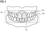
- Fig. 4 shows a schematic representation of an imaging region 18 of the magnetic resonance imaging system 10 according to the invention.
- a height of the imaging volume 19 may be chosen in such a way, that a tooth of an upper dental arch 41a and a lower dental arch 41b are encompassed by the imaging volume 19.
- magnetic resonance signals may be acquired from the imaging region 18 covering both dental arches 41a and 41b of the patient 15.
- the magnetic resonance imaging examination of the jaw region of the patient 15 may also be divided into a first examination covering the upper dental arch 41a and a second examination covering the lower dental arch 41b. Preferably, this may be accomplished by either moving the magnetic field generation unit 13 along the Y-direction via the support system 11 or by moving the patient 15 via the patient positioning device 16 (see Fig. 1 ).
- Fig. 5 shows a schematic representation of another embodiment of the magnetic field generation unit 13.
- the magnetic field generation unit 13 comprises a first magnet 17a and a second magnet 17b arranged in a predefined relative position along the rotation trajectory 32.
- the first magnet 17a generates a first imaging volume 19a and the second magnet 17b generates a second imaging volume 19b within the image acquisition region 14.
- the first magnet 17a may positioned at the first end position 37 on the rotation trajectory 32, whereas the second magnet 17b may be positioned at a predefined position 39 on the rotation trajectory 32.
- an imaging region 18 covering the dental arch 41 of the patient 15 may be subdivided into an imaging region 18a covered by the first magnet 17a and an imaging region 18b covered by the second magnet 17b.
- an angle 70a between the first magnet 17a and the second magnet 17b amounts to 90°.
- other higher or lower values are also conceivable.
- shimming elements 50 may be positioned at the first magnet 17a and the second magnet 17b.
- the shimming elements 50 may be active shim coils or passive shim irons which may be configured to at least partially encompass the first magnet 17a and the second magnet 17b along a circumferential direction.
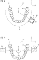
- Fig. 6 depicts a schematic representation of a magnetic field gradient system 60 of a magnetic resonance imaging system 10 according to the invention.
- the magnetic field gradient system 60 comprises a gradient coil 61 which is positioned on the rotation trajectory 32.
- the gradient coil 61 may be carried by the magnet holder 33 as shown in Fig. 3 or by a dedicated gradient coil holder 62 as depicted in Fig. 6 .
- the gradient coil holder 62 may be mounted on a carrier element 81 of a mechanical guiding rail 80 as depicted in Fig. 9 . It is also conceivable, that the gradient coil 61 is arranged on the magnet 17 as depicted in Fig. 3 .
- the gradient coil 61 is configured to generate a magnetic gradient field (not shown) which may be used for spatial encoding of magnetic resonance signals acquired from an imaging region 18 within the image acquisition region 14.
- the gradient coil 61 is configured to provide a magnetic gradient field oriented along a cranio-caudal direction of the patient 15.
- the gradient coil 61 may be moved along the rotation trajectory 32 in a unilateral manner. Particularly, the gradient coil 61 may be guided azimuthally along the dental arch 41 of the patient 15.
- Fig. 7 holds a schematic representation of a further embodiment of the magnetic field gradient system 60.
- the magnetic field gradient system 60 comprises a first gradient coil 61a and a second gradient coil 61b arranged at a 180° angle on the rotation trajectory 32.
- the first gradient coil 61a and the second gradient coil 61b may be rotated around the rotation center 31 in a bilateral manner.
- the gradient coil 61a and the gradient coil 61b may generate a first magnetic gradient field and a second magnetic gradient (not shown) within the image acquisition region 14. It is also conceivable, that the first magnetic gradient field overlaps with the first imaging volume 19a, while the second magnetic gradient field overlaps with the second imaging volume 19b.
- the angle 70b may correspond to the angle 70a as depicted in Fig. 5 .
- the first gradient coil 61a and the second gradient coil 61b may also act as magnetic poles with different magnetic field strengths, thus generating a magnetic gradient field across the entire image acquisition region 14.
- a further embodiment of the magnetic field gradient system 60 is depicted.
- the magnetic field gradient system 60 encloses the imaging acquisition region 14 and the jaw region of the patient 15 in a circumferential direction.
- one or more gradient coils as for example a first gradient coil, a second gradient coil and a third gradient coil, as well as a radiofrequency antenna, are wound around a cylindrical section of the magnetic field gradient system 60.
- Each gradient coil may be arranged in such a way to at least partially enclose the image acquisition region 14.
- an arrangement of the gradient coils and/or the radiofrequency antenna may correspond to an arrangement of gradient coils and/or a radiofrequency antenna in a conventional cylindrical magnetic resonance imaging system.
- the gradient coil 61 depicted in Fig. 8 as well as further gradient coils and/or the radiofrequency antenna may therefore comprise a fixed position with regard to the image acquisition region 14 during a magnetic resonance imaging examination.
- Fig. 9 shows a schematic representation of a mechanical guiding rail 80 of a rotation system 30.
- the representation of the rotation system 30 corresponds to a view that a patient 15 would have, when looking along the Z-direction into the magnetic field generation unit 13 as depicted in Fig. 1 .
- the guiding rail 80 is embedded in an arc-shaped element 82 of the rotation system 30 and may comprise a perimeter which is positioned parallelly and/or concentrically to the rotation trajectory 32.
- a course of the mechanical guiding rail 80 may also be regarded as a rotation trajectory 32.
- the magnet holder 33 may be carried by a carrier element 81 which is shaped to interlock with a T-shaped groove provided by the mechanical guiding rail 80.
- the magnet 17 may in turn be carried by the magnet holder 33. As shown in Fig. 9 , the magnet 17 is oriented in a direction of the image acquisition region 14. When the carrier element 81 is moved along the mechanical guiding rail 80, the magnet 17 may be moved along the rotation trajectory 32 as shown in Fig. 3 .
- the carrier element 81 may comprise a ball bearing system (not shown) in order to provide a low-friction transport of the magnet holder along the rotation trajectory 32. It is also conceivable, that the carrier element 81 and the magnet holder 33 are driven or moved by a motor (not shown) which may be mounted on the arc-shaped element 82 of the rotation system 30.
- Fig. 10 holds a depiction of a magnetic resonance imaging system 10, wherein the first magnet 17a is an electromagnet configured to generate a pulsed first magnetic field inside the imaging volume 19.
- the pulsed first magnetic field may be configured to pre-polarize nuclear spins inside the imaging volume 19.
- the second magnet 17b may be an electromagnet or a superconducting magnet configured to generate a homogenous second magnetic field in the imaging volume 19.
- the second magnet 17b may also be permanent magnet.
- the first magnet 17a and the second magnet 17b are moved along the rotation trajectory 32 via the magnet holder 33 in a step-by-step fashion in such a way that magnetic resonance signals can be acquired from the imaging region 18 in each step.
- the second magnet 17b circumferentially encompasses the image acquisition region 14 as well as the head of the patient 15 (not shown). In this case, the second magnet 17b remains in a fixed position while the first magnet 17a is moved along the rotation trajectory 32.
Landscapes
- Health & Medical Sciences (AREA)
- Physics & Mathematics (AREA)
- Life Sciences & Earth Sciences (AREA)
- Condensed Matter Physics & Semiconductors (AREA)
- General Physics & Mathematics (AREA)
- Public Health (AREA)
- Animal Behavior & Ethology (AREA)
- Nuclear Medicine, Radiotherapy & Molecular Imaging (AREA)
- Biophysics (AREA)
- Pathology (AREA)
- Engineering & Computer Science (AREA)
- Biomedical Technology (AREA)
- Heart & Thoracic Surgery (AREA)
- Medical Informatics (AREA)
- Molecular Biology (AREA)
- Surgery (AREA)
- Veterinary Medicine (AREA)
- General Health & Medical Sciences (AREA)
- High Energy & Nuclear Physics (AREA)
- Radiology & Medical Imaging (AREA)
- Physical Education & Sports Medicine (AREA)
- Dentistry (AREA)
- Oral & Maxillofacial Surgery (AREA)
- Orthopedic Medicine & Surgery (AREA)
- Rheumatology (AREA)
- Magnetic Resonance Imaging Apparatus (AREA)
Applications Claiming Priority (3)
| Application Number | Priority Date | Filing Date | Title |
|---|---|---|---|
| US201962941348P | 2019-11-27 | 2019-11-27 | |
| US201962941268P | 2019-11-27 | 2019-11-27 | |
| US201962941140P | 2019-11-27 | 2019-11-27 |
Publications (3)
| Publication Number | Publication Date |
|---|---|
| EP3828575A2 true EP3828575A2 (fr) | 2021-06-02 |
| EP3828575A3 EP3828575A3 (fr) | 2021-08-25 |
| EP3828575B1 EP3828575B1 (fr) | 2025-08-27 |
Family
ID=73005347
Family Applications (1)
| Application Number | Title | Priority Date | Filing Date |
|---|---|---|---|
| EP20202953.4A Active EP3828575B1 (fr) | 2019-11-27 | 2020-10-21 | Système d'imagerie par résonance magnétique doté d'un aimant rotatif |
Country Status (2)
| Country | Link |
|---|---|
| US (1) | US11304653B2 (fr) |
| EP (1) | EP3828575B1 (fr) |
Families Citing this family (3)
| Publication number | Priority date | Publication date | Assignee | Title |
|---|---|---|---|---|
| EP3827746A1 (fr) * | 2019-11-27 | 2021-06-02 | Siemens Healthcare GmbH | Flux de travail pour un système d'imagerie par résonance magnétique dédié |
| EP4113146B1 (fr) * | 2021-06-30 | 2025-05-07 | Siemens Healthineers AG | Dispositif d'imagerie par résonance magnétique comportant une unité de génération de champ de forme concave |
| EP4290261A1 (fr) | 2022-06-07 | 2023-12-13 | Siemens Healthcare GmbH | Système de résonance magnétique et procédé correspondant |
Family Cites Families (9)
| Publication number | Priority date | Publication date | Assignee | Title |
|---|---|---|---|---|
| US6570383B1 (en) * | 2000-12-27 | 2003-05-27 | Ge Medical Systems Global Technology Company, Llc | Method and apparatus for a pulse sequence for magnetic resonance imaging in an inhomogeneous magnetic field |
| US7737693B2 (en) * | 2006-03-04 | 2010-06-15 | Tursiop Technologies Llc | Signal acquisition and processing method and apparatus for magnetic resonance imaging |
| DE102009026897A1 (de) * | 2009-06-10 | 2010-12-16 | Sirona Dental Systems Gmbh | Sensor sowie Magnetfeldeinheit zur Verwendung innerhalb eines Magnetresonanztomographie-Systems oder eines Magnetresonanzspektroskopie-Systems |
| US9910115B2 (en) * | 2012-10-22 | 2018-03-06 | The General Hospital Corporation | System and method for portable magnetic resonance imaging using a rotating array of magnets |
| DE102013226745A1 (de) | 2013-12-19 | 2015-06-25 | Sirona Dental Systems Gmbh | Magnetresonanz-Abtastvorrichtung für die medizinische Diagnostik |
| US10539637B2 (en) * | 2016-11-22 | 2020-01-21 | Hyperfine Research, Inc. | Portable magnetic resonance imaging methods and apparatus |
| EP3349029B1 (fr) | 2017-01-13 | 2019-09-11 | Sirona Dental Systems GmbH | Dispositif irm de mesure d'au moins une zone partielle d'une tête |
| US20210031055A1 (en) | 2018-04-11 | 2021-02-04 | Board Of Regents Of The University Of Texas System | Mri adaptation for radiotherapy machines |
| EP3827746A1 (fr) * | 2019-11-27 | 2021-06-02 | Siemens Healthcare GmbH | Flux de travail pour un système d'imagerie par résonance magnétique dédié |
-
2020
- 2020-10-21 EP EP20202953.4A patent/EP3828575B1/fr active Active
- 2020-11-23 US US17/101,539 patent/US11304653B2/en active Active
Also Published As
| Publication number | Publication date |
|---|---|
| US20210156938A1 (en) | 2021-05-27 |
| EP3828575B1 (fr) | 2025-08-27 |
| EP3828575A3 (fr) | 2021-08-25 |
| US11304653B2 (en) | 2022-04-19 |
Similar Documents
| Publication | Publication Date | Title |
|---|---|---|
| US12044759B2 (en) | Toroidal system configuration for dedicated MRI scanners | |
| JP7638358B2 (ja) | 介入のための開口を備える片側磁気共鳴画像システムおよび当該システムを動作させるための手法 | |
| JP7098539B2 (ja) | 磁気共鳴イメージング | |
| CA2880312C (fr) | Systeme de radiotherapie integrant une source de rayonnement avec un appareil d'imagerie par resonance magnetique avec des composants d'aimant mobiles | |
| US8358737B2 (en) | Apparatus and method for X-ray treatment | |
| EP3828575B1 (fr) | Système d'imagerie par résonance magnétique doté d'un aimant rotatif | |
| US20130274590A1 (en) | Method and apparatus for generating a signal indicative of motion of a subject in a magnetic resonance apparatus | |
| US20150338477A1 (en) | An active tracking system and method for mri | |
| KR101743185B1 (ko) | 심 코일 디바이스 및 심 코일 디바이스를 갖는 자기 공명 코일 시스템 | |
| KR20160133506A (ko) | 로우-필드, 다중-채널 이미징을 위한 시스템 및 방법 | |
| JPWO2002022012A1 (ja) | 磁気共鳴イメージング装置 | |
| US11768263B2 (en) | Magnet system for a magnetic resonance imaging system | |
| WO2007029139A2 (fr) | Systeme de poursuite magnetique pour systeme d'imagerie | |
| US10578691B2 (en) | Gradient magnetic field generation module using plurality of coils so as to generate gradient magnetic field | |
| US10823793B2 (en) | Resonance data acquisition scanner with rotating basic field magnet | |
| WO2022242593A1 (fr) | Imagerie par résonance magnétique (irm) améliorée à permittivité et spectroscopie par résonance magnétique (srm) | |
| US20190170838A1 (en) | Coil apparatus, magnetic resonance imaging apparatus, and method of controlling the coil apparatus | |
| US20210220675A1 (en) | Radiation therapy apparatus, medical image processing apparatus, and medical image processing method | |
| JP4031964B2 (ja) | 磁気共鳴イメージング装置用受信コイル及びこれを用いた装置 | |
| CN109562275B (zh) | 磁共振成像引导的治疗系统及介质 | |
| JP2003116812A (ja) | 磁場発生装置及びこれを用いるmri装置 | |
| US20250264559A1 (en) | Low-field magnetic resonance flow imaging | |
| JP2018529441A (ja) | デバイスの位置確認方法、磁気共鳴撮像システム及びコンピュータ・プログラム | |
| Yelleswarapu et al. | TOP-level designs of a hybrid low field MRI-CT system for pulmonary imaging | |
| WO2017093090A1 (fr) | Système de bobines rf, produit programme d'ordinateur et système d'imagerie par résonance magnétique |
Legal Events
| Date | Code | Title | Description |
|---|---|---|---|
| PUAI | Public reference made under article 153(3) epc to a published international application that has entered the european phase |
Free format text: ORIGINAL CODE: 0009012 |
|
| STAA | Information on the status of an ep patent application or granted ep patent |
Free format text: STATUS: THE APPLICATION HAS BEEN PUBLISHED |
|
| AK | Designated contracting states |
Kind code of ref document: A2 Designated state(s): AL AT BE BG CH CY CZ DE DK EE ES FI FR GB GR HR HU IE IS IT LI LT LU LV MC MK MT NL NO PL PT RO RS SE SI SK SM TR |
|
| STAA | Information on the status of an ep patent application or granted ep patent |
Free format text: STATUS: REQUEST FOR EXAMINATION WAS MADE |
|
| 17P | Request for examination filed |
Effective date: 20210604 |
|
| RBV | Designated contracting states (corrected) |
Designated state(s): AL AT BE BG CH CY CZ DE DK EE ES FI FR GB GR HR HU IE IS IT LI LT LU LV MC MK MT NL NO PL PT RO RS SE SI SK SM TR |
|
| PUAL | Search report despatched |
Free format text: ORIGINAL CODE: 0009013 |
|
| AK | Designated contracting states |
Kind code of ref document: A3 Designated state(s): AL AT BE BG CH CY CZ DE DK EE ES FI FR GB GR HR HU IE IS IT LI LT LU LV MC MK MT NL NO PL PT RO RS SE SI SK SM TR |
|
| RIC1 | Information provided on ipc code assigned before grant |
Ipc: G01R 33/38 20060101AFI20210720BHEP Ipc: A61B 5/055 20060101ALI20210720BHEP Ipc: A61B 5/00 20060101ALI20210720BHEP Ipc: G01R 33/44 20060101ALN20210720BHEP |
|
| RAP1 | Party data changed (applicant data changed or rights of an application transferred) |
Owner name: SIEMENS HEALTHINEERS AG |
|
| STAA | Information on the status of an ep patent application or granted ep patent |
Free format text: STATUS: EXAMINATION IS IN PROGRESS |
|
| 17Q | First examination report despatched |
Effective date: 20240514 |
|
| GRAP | Despatch of communication of intention to grant a patent |
Free format text: ORIGINAL CODE: EPIDOSNIGR1 |
|
| STAA | Information on the status of an ep patent application or granted ep patent |
Free format text: STATUS: GRANT OF PATENT IS INTENDED |
|
| RIC1 | Information provided on ipc code assigned before grant |
Ipc: G01R 33/44 20060101ALN20250407BHEP Ipc: A61B 5/00 20060101ALI20250407BHEP Ipc: A61B 5/055 20060101ALI20250407BHEP Ipc: G01R 33/38 20060101AFI20250407BHEP |
|
| INTG | Intention to grant announced |
Effective date: 20250425 |
|
| GRAS | Grant fee paid |
Free format text: ORIGINAL CODE: EPIDOSNIGR3 |
|
| GRAA | (expected) grant |
Free format text: ORIGINAL CODE: 0009210 |
|
| STAA | Information on the status of an ep patent application or granted ep patent |
Free format text: STATUS: THE PATENT HAS BEEN GRANTED |
|
| AK | Designated contracting states |
Kind code of ref document: B1 Designated state(s): AL AT BE BG CH CY CZ DE DK EE ES FI FR GB GR HR HU IE IS IT LI LT LU LV MC MK MT NL NO PL PT RO RS SE SI SK SM TR |
|
| REG | Reference to a national code |
Ref country code: GB Ref legal event code: FG4D |
|
| REG | Reference to a national code |
Ref country code: CH Ref legal event code: EP |
|
| REG | Reference to a national code |
Ref country code: DE Ref legal event code: R096 Ref document number: 602020057307 Country of ref document: DE |
|
| REG | Reference to a national code |
Ref country code: IE Ref legal event code: FG4D |
|
| REG | Reference to a national code |
Ref country code: NL Ref legal event code: MP Effective date: 20250827 |
|
| PG25 | Lapsed in a contracting state [announced via postgrant information from national office to epo] |
Ref country code: IS Free format text: LAPSE BECAUSE OF FAILURE TO SUBMIT A TRANSLATION OF THE DESCRIPTION OR TO PAY THE FEE WITHIN THE PRESCRIBED TIME-LIMIT Effective date: 20251227 |
|
| PGFP | Annual fee paid to national office [announced via postgrant information from national office to epo] |
Ref country code: GB Payment date: 20251111 Year of fee payment: 6 |
|
| PG25 | Lapsed in a contracting state [announced via postgrant information from national office to epo] |
Ref country code: NO Free format text: LAPSE BECAUSE OF FAILURE TO SUBMIT A TRANSLATION OF THE DESCRIPTION OR TO PAY THE FEE WITHIN THE PRESCRIBED TIME-LIMIT Effective date: 20251127 |
|
| REG | Reference to a national code |
Ref country code: LT Ref legal event code: MG9D |
|
| PG25 | Lapsed in a contracting state [announced via postgrant information from national office to epo] |
Ref country code: PT Free format text: LAPSE BECAUSE OF FAILURE TO SUBMIT A TRANSLATION OF THE DESCRIPTION OR TO PAY THE FEE WITHIN THE PRESCRIBED TIME-LIMIT Effective date: 20251229 |
|
| PG25 | Lapsed in a contracting state [announced via postgrant information from national office to epo] |
Ref country code: FI Free format text: LAPSE BECAUSE OF FAILURE TO SUBMIT A TRANSLATION OF THE DESCRIPTION OR TO PAY THE FEE WITHIN THE PRESCRIBED TIME-LIMIT Effective date: 20250827 |
|
| PG25 | Lapsed in a contracting state [announced via postgrant information from national office to epo] |
Ref country code: NL Free format text: LAPSE BECAUSE OF FAILURE TO SUBMIT A TRANSLATION OF THE DESCRIPTION OR TO PAY THE FEE WITHIN THE PRESCRIBED TIME-LIMIT Effective date: 20250827 Ref country code: HR Free format text: LAPSE BECAUSE OF FAILURE TO SUBMIT A TRANSLATION OF THE DESCRIPTION OR TO PAY THE FEE WITHIN THE PRESCRIBED TIME-LIMIT Effective date: 20250827 |
|
| PGFP | Annual fee paid to national office [announced via postgrant information from national office to epo] |
Ref country code: FR Payment date: 20251020 Year of fee payment: 6 |
|
| PG25 | Lapsed in a contracting state [announced via postgrant information from national office to epo] |
Ref country code: GR Free format text: LAPSE BECAUSE OF FAILURE TO SUBMIT A TRANSLATION OF THE DESCRIPTION OR TO PAY THE FEE WITHIN THE PRESCRIBED TIME-LIMIT Effective date: 20251128 |
|
| PG25 | Lapsed in a contracting state [announced via postgrant information from national office to epo] |
Ref country code: SE Free format text: LAPSE BECAUSE OF FAILURE TO SUBMIT A TRANSLATION OF THE DESCRIPTION OR TO PAY THE FEE WITHIN THE PRESCRIBED TIME-LIMIT Effective date: 20250827 |
|
| PG25 | Lapsed in a contracting state [announced via postgrant information from national office to epo] |
Ref country code: LV Free format text: LAPSE BECAUSE OF FAILURE TO SUBMIT A TRANSLATION OF THE DESCRIPTION OR TO PAY THE FEE WITHIN THE PRESCRIBED TIME-LIMIT Effective date: 20250827 |
|
| PG25 | Lapsed in a contracting state [announced via postgrant information from national office to epo] |
Ref country code: BG Free format text: LAPSE BECAUSE OF FAILURE TO SUBMIT A TRANSLATION OF THE DESCRIPTION OR TO PAY THE FEE WITHIN THE PRESCRIBED TIME-LIMIT Effective date: 20250827 Ref country code: PL Free format text: LAPSE BECAUSE OF FAILURE TO SUBMIT A TRANSLATION OF THE DESCRIPTION OR TO PAY THE FEE WITHIN THE PRESCRIBED TIME-LIMIT Effective date: 20250827 |
|
| PG25 | Lapsed in a contracting state [announced via postgrant information from national office to epo] |
Ref country code: RS Free format text: LAPSE BECAUSE OF FAILURE TO SUBMIT A TRANSLATION OF THE DESCRIPTION OR TO PAY THE FEE WITHIN THE PRESCRIBED TIME-LIMIT Effective date: 20251127 |
|
| PG25 | Lapsed in a contracting state [announced via postgrant information from national office to epo] |
Ref country code: ES Free format text: LAPSE BECAUSE OF FAILURE TO SUBMIT A TRANSLATION OF THE DESCRIPTION OR TO PAY THE FEE WITHIN THE PRESCRIBED TIME-LIMIT Effective date: 20250827 |
|
| REG | Reference to a national code |
Ref country code: AT Ref legal event code: MK05 Ref document number: 1830498 Country of ref document: AT Kind code of ref document: T Effective date: 20250827 |
|
| PG25 | Lapsed in a contracting state [announced via postgrant information from national office to epo] |
Ref country code: RO Free format text: LAPSE BECAUSE OF FAILURE TO SUBMIT A TRANSLATION OF THE DESCRIPTION OR TO PAY THE FEE WITHIN THE PRESCRIBED TIME-LIMIT Effective date: 20250827 |
|
| PG25 | Lapsed in a contracting state [announced via postgrant information from national office to epo] |
Ref country code: SM Free format text: LAPSE BECAUSE OF FAILURE TO SUBMIT A TRANSLATION OF THE DESCRIPTION OR TO PAY THE FEE WITHIN THE PRESCRIBED TIME-LIMIT Effective date: 20250827 |
|
| PG25 | Lapsed in a contracting state [announced via postgrant information from national office to epo] |
Ref country code: DK Free format text: LAPSE BECAUSE OF FAILURE TO SUBMIT A TRANSLATION OF THE DESCRIPTION OR TO PAY THE FEE WITHIN THE PRESCRIBED TIME-LIMIT Effective date: 20250827 |
|
| PGFP | Annual fee paid to national office [announced via postgrant information from national office to epo] |
Ref country code: DE Payment date: 20251219 Year of fee payment: 6 |
|
| PG25 | Lapsed in a contracting state [announced via postgrant information from national office to epo] |
Ref country code: AT Free format text: LAPSE BECAUSE OF FAILURE TO SUBMIT A TRANSLATION OF THE DESCRIPTION OR TO PAY THE FEE WITHIN THE PRESCRIBED TIME-LIMIT Effective date: 20250827 |
|
| PG25 | Lapsed in a contracting state [announced via postgrant information from national office to epo] |
Ref country code: IT Free format text: LAPSE BECAUSE OF FAILURE TO SUBMIT A TRANSLATION OF THE DESCRIPTION OR TO PAY THE FEE WITHIN THE PRESCRIBED TIME-LIMIT Effective date: 20250827 |
|
| PG25 | Lapsed in a contracting state [announced via postgrant information from national office to epo] |
Ref country code: CZ Free format text: LAPSE BECAUSE OF FAILURE TO SUBMIT A TRANSLATION OF THE DESCRIPTION OR TO PAY THE FEE WITHIN THE PRESCRIBED TIME-LIMIT Effective date: 20250827 |
|
| PG25 | Lapsed in a contracting state [announced via postgrant information from national office to epo] |
Ref country code: SK Free format text: LAPSE BECAUSE OF FAILURE TO SUBMIT A TRANSLATION OF THE DESCRIPTION OR TO PAY THE FEE WITHIN THE PRESCRIBED TIME-LIMIT Effective date: 20250827 Ref country code: EE Free format text: LAPSE BECAUSE OF FAILURE TO SUBMIT A TRANSLATION OF THE DESCRIPTION OR TO PAY THE FEE WITHIN THE PRESCRIBED TIME-LIMIT Effective date: 20250827 |