EP3828667A1 - Blende für ein tragbares gerät - Google Patents
Blende für ein tragbares gerät Download PDFInfo
- Publication number
- EP3828667A1 EP3828667A1 EP20210498.0A EP20210498A EP3828667A1 EP 3828667 A1 EP3828667 A1 EP 3828667A1 EP 20210498 A EP20210498 A EP 20210498A EP 3828667 A1 EP3828667 A1 EP 3828667A1
- Authority
- EP
- European Patent Office
- Prior art keywords
- blades
- shade
- planar surface
- mount
- user
- Prior art date
- Legal status (The legal status is an assumption and is not a legal conclusion. Google has not performed a legal analysis and makes no representation as to the accuracy of the status listed.)
- Granted
Links
Images

Classifications
-
- G—PHYSICS
- G06—COMPUTING OR CALCULATING; COUNTING
- G06F—ELECTRIC DIGITAL DATA PROCESSING
- G06F1/00—Details not covered by groups G06F3/00 - G06F13/00 and G06F21/00
- G06F1/16—Constructional details or arrangements
- G06F1/1601—Constructional details related to the housing of computer displays, e.g. of CRT monitors, of flat displays
- G06F1/1603—Arrangements to protect the display from incident light, e.g. hoods
-
- A—HUMAN NECESSITIES
- A45—HAND OR TRAVELLING ARTICLES
- A45B—WALKING STICKS; UMBRELLAS; LADIES' OR LIKE FANS
- A45B23/00—Other umbrellas
-
- G—PHYSICS
- G06—COMPUTING OR CALCULATING; COUNTING
- G06F—ELECTRIC DIGITAL DATA PROCESSING
- G06F1/00—Details not covered by groups G06F3/00 - G06F13/00 and G06F21/00
- G06F1/16—Constructional details or arrangements
- G06F1/1613—Constructional details or arrangements for portable computers
- G06F1/1626—Constructional details or arrangements for portable computers with a single-body enclosure integrating a flat display, e.g. Personal Digital Assistants [PDAs]
-
- H—ELECTRICITY
- H04—ELECTRIC COMMUNICATION TECHNIQUE
- H04M—TELEPHONIC COMMUNICATION
- H04M1/00—Substation equipment, e.g. for use by subscribers
- H04M1/02—Constructional features of telephone sets
- H04M1/0202—Portable telephone sets, e.g. cordless phones, mobile phones or bar type handsets
- H04M1/026—Details of the structure or mounting of specific components
-
- H—ELECTRICITY
- H04—ELECTRIC COMMUNICATION TECHNIQUE
- H04M—TELEPHONIC COMMUNICATION
- H04M1/00—Substation equipment, e.g. for use by subscribers
- H04M1/02—Constructional features of telephone sets
- H04M1/0202—Portable telephone sets, e.g. cordless phones, mobile phones or bar type handsets
- H04M1/0279—Improving the user comfort or ergonomics
-
- H—ELECTRICITY
- H04—ELECTRIC COMMUNICATION TECHNIQUE
- H04M—TELEPHONIC COMMUNICATION
- H04M1/00—Substation equipment, e.g. for use by subscribers
- H04M1/02—Constructional features of telephone sets
- H04M1/04—Supports for telephone transmitters or receivers
-
- H—ELECTRICITY
- H04—ELECTRIC COMMUNICATION TECHNIQUE
- H04M—TELEPHONIC COMMUNICATION
- H04M1/00—Substation equipment, e.g. for use by subscribers
- H04M1/02—Constructional features of telephone sets
- H04M1/21—Combinations with auxiliary equipment, e.g. with clocks or memoranda pads
-
- A—HUMAN NECESSITIES
- A45—HAND OR TRAVELLING ARTICLES
- A45B—WALKING STICKS; UMBRELLAS; LADIES' OR LIKE FANS
- A45B23/00—Other umbrellas
- A45B2023/0093—Sunshades or weather protections of other than umbrella type
Definitions
- the present invention relates to a shade for a portable device, in particular a shade for providing a shading surface for a portable device when placed between a user and a light source.
- portable devices Unlike a book that can be held above the user between the user and the sun, portable devices typically have a surface area that is not adequate to stop sunlight from penetrating the user's eyes. Sunlight instead is able to pass around the sides/over the top of the phone, penetrating the user's eye.
- CN105357340 Mobile phone accessories and the like that attach to the electronic device are known, CN105357340 .describes a dual-purpose mobile phone shell.
- the mobile phone shell body is manufactured into a structure, which can be stretched and is particularly provided with a handle; and thus, the mobile phone shell body can be used as a fan.
- the shell described therein utilises a fan, with no consideration given to providing shade to user during use of the device. Additionally, said fan is fixed in relation to the phone and cannot be repositioned to suit the screen viewing orientation or sun direction.
- US2017279944 shows a mobile device shade apparatus that includes a case defining a pocket and at least one panel configured to travel in and out of the pocket to transition between a stowed state and a deployed state, wherein in the deployed state that at least one panel extends from and is rotatable with respect to an edge of the case.
- the apparatus also includes a coupler configured to couple the case to a mobile device, such as a cell phone or tablet, as examples.
- a mobile device such as a cell phone or tablet
- this device focusses solely on casting shade over the electronic device screen, akin to countersinking the display like a shade for a car dashboard, with no regard given to user's holding the device between themselves and the sun. Accordingly, such shade acts to reduce glare and reflections from the mobile device screen only.
- the present invention aims to at least ameliorate the aforementioned disadvantages faced by users of portable devices in the sunlight.
- a shade for a portable device having an electronic display, said shade comprising: a plurality of blades configured to splay open to form a planar or fanned surface for blocking sunlight; and a mount for securing the planar surface substantially adjacent to the electronic display to position the blades to provide a shading surface when the planar surface is placed between a user and a light source.
- the shade of the present invention provides for a shade designed to mount and connect to a portable display device such as a mobile phone, e-book reader, tablet device, handheld gaming device, laptop, notebook or the like.
- a portable display device such as a mobile phone, e-book reader, tablet device, handheld gaming device, laptop, notebook or the like.
- blades allow the shade to form a planar surface easily, with the blades fanned out when shade against sunlight is needed, and to be collapsed when the planar surface is not needed.
- planar surface advantageously provides for an increased footprint of the device when held against the sun. Accordingly, if a device with the shade is placed between a user and the sun a larger area of the user's face is cast in shadow making for more comfortable reading of the screen of the device by the user.
- planar surface may be provided with motifs, designs or the like. This provides an additional level of customisation to a user, allowing creative expression similar to a mobile phone cover or the like.
- the shade may be configured to form the planar surface by rotating the fan blades relative to each other about a rivet.
- the blades may comprise additional blades configured to splay outwards from the blades to form the planar surface between blades.
- the blades may be vertically offset to lie on top of each other in a closed position, such that a surface of each fan blade can substantially overlap with the surface of other fan blades. This configuration allows the shade to take up minimum space when not needed.
- a clip may be provided on an end of a blade to lock the blades against the rivet in this closed configuration.
- the planar surface may lie adjacent to a display of the portable display device. As noted above, this can provide an increased shading surface than the shade cast by the device alone. In such embodiments the planar surface may be considered as a visor.
- planar surface and the display form a continuous shading surface for shading the eyes of a user from a light source when placed between the user and the light source. This ensures that there are no gaps through which sunlight can pass onto a user's face when the shade and device are held between the user's face and a light source (typically the sun).
- planar surface may be rotatable such that the surface is configured to form an angle with the display of the portable electronic device. This can allow a user to adjust the angle of the shade to maximise the shading surface if the user is viewing the device at an angle relative to the sun.
- the fan blades of the planar surface may be displaced relative to each other, such that a surface area of each fan blade substantially does not overlap with any other fan blade.
- the planar surface may form a hemicircular shape.
- the hemicircular shape spans 180 degrees of a circle.
- the shape may span between 140 and 220 degrees of a circle.
- the planar surface may form a substantially rectangular shape.
- the plurality of blades may each comprise a hole at one end of the blades. Accordingly, the blades may be connected to each other via the rivet inserted into the holes.
- a washer may be placed between an uppermost of the blades and a head of the rivet. The use of a washer can increase the coefficient of friction between the blades and the rivet to aid the blades staying in the planar position.
- the mount may comprise a ball joint for rotating the blades and therefore the planar surface relative to the electronic display device. This can allow the blades and therefore the planar surface, and therefore at least part of the shading surface to be positioned between the user and the sun when the user is unable to reposition themselves, such as when the user is lying on a sunbed or the like.
- the mount may be or comprise a suction cup, said suction cup configured to be removably attached to a back surface of the portable display device. Additionally or alternatively the mount may be integrated with a protective case of the like.
- a length of the blades may be tailored to match a width of the portable display device.
- the diameter of the hemicircle may be substantially equal to the width of the device.
- a wider diameter of hemicircle may be used.
- the blades may comprise an interlocking groove to receive a corresponding interlocking nub of an adjacent blade. This effectively lock the blades against each other.
- the blades may further comprise an end stop to prevent over rotation of the blades. This can act to ensure that the blades are retained in the planar position and ensure that gaps are not present between the blades when fanned out.
- the mount provides a finger rest. This can allow a user to hold the device and fan using the mount, for ease of use.
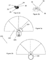
- Figure 1a shows a part of the shade 1, comprising a plurality of fan blades 2.
- Each blade is typically a segment of a circle.
- Each blade typically comprises a segment having an angle of approximately 25 degrees. In the example shown, four blades 2 are shown, however it can be appreciated that more or less blades 2 may be used as needed.
- the base of the blade 2 further comprises a circular pivot point 4.
- each fan blade 2 has a 2-dimensional cone like geometry like the ones shown figure 1 .
- the fan blades can take any suitable geometry such as, for example, rectangular shaped blades 2.
- the pivot point 4 contains an aperture 5 through which a blade retainer rivet 8 is inserted from one side of the blade 2 to connect the blades together and to a mount 6.
- a blade retainer rivet 8 is inserted from one side of the blade 2 to connect the blades together and to a mount 6.
- FIG 1b shows an expanded view of the components that comprise the shade 1 and in more detail in figure 1c .
- the blade retainer rivet 8 comprises a disk 10 with elongated shaft 12 protruding from the centre of the disk, as shown in figure 1c .
- the shaft 12 of the retainer rivet 8 is inserted through all the apertures 5 of the blades 2 from one side as shown in figure 1b .
- the remaining tip of the shaft 12 that extends beyond the end of the apertures 5 is then inserted into an end 14 of an arm lever 16.
- the part of the level arm 16 that contains the end 14 makes contact with the pivot point 4 of the upper most blade 2a as shown in figure 1b .
- a rubber washer 18 is inserted between pivot point 4 of the upper most blade 2a and the arm lever 16 to provide a higher coefficient of friction between the arm lever 16 and the upper most blade. This aids the fanning shape shown in figure 1b to stay open.
- the fan blades 2 can be configured into a closed ( figures 1a ) or an open position ( figures 1b ) by the rotation of the fan blades 2 relative to each other by the user about the pivot point 4. When in the closed position each fan blade 2 overlaps with all other fan blades 2.
- the fan blades 2 can be configured into an open position by rotation of the blades 2 relative to each other about the pivot point 4 by the users, such that the fan blades 2 are displaced relative to each other as shown in figure 1b .
- the fan blades 2 span a total area subtending an angle of 180 degrees in the open position. This arrangement is found to be sufficient to block substantially all of the sunlight that would otherwise enter the user's macular, thus allowing the user to read from a screen of the device properly.
- the mount 6 further comprises a suction cup housing 20 to which the arm lever 16 is connected.
- the suction cup housing 20 houses a suction cup tension link 24.
- the tension link 24 comprises a hollow cylindrical top 26 and a hollow rectangular base 28, as shown in figure 2a .
- the cylindrical top 26 comprises an opening 27 that allows the tension link 24 to be connected to the arm lever 16 and the cup housing via a pin 22 in a manner shown in figure 1b .
- the rectangular base 28 is further configured to be attached to suction cup 32. This is achieved by inserting a suction cup head 36 (shown in figure 2b ) into the rectangular base 28 and securing the head 36 to the base 28 by using a pin 34, in a manner shown in figure 1b .
- the suction cup 32 further comprises a suction disk 38 configured to be removably attached to a back of an electronic display device, such that the shade 1 is secured to the device. Collectively, this allows the mount 6 to attach the shade 1 to the device.
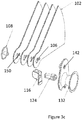
- Figures 3a and 3b show a shade 100 according to an alternative embodiment of the present invention.
- the blade comprises blades 102 arranged about a common pivot point 104 that is further connected to a mount 106.
- FIG 3b shows an exploded view of the shade 100 of figures 3a and 3b .
- the blades 102 are interconnected with a rivet 108 or pin that acts to retain the blades together against a corresponding hole 142 in the mount 106.
- the rivet allows for relative rotation of the blades 102 about the rivet 108.
- the mount 106 is provided with a suction cup 132 having a lever arm 116 and tension link 124 that acts to secure the suction cup 132 to a device in an analogous manner to described in relation to the previous figures.
- the blades 102 are further provided with end stops 150 that act to provide tactile and physical ends such that adjacent blades 102 are held in a planar position when the blades are fanned open. Accordingly, an edge of a blade 102 abuts the end stop 150 of an adjacent blade to hold the blades in relative position.
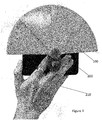
- FIG 4 shows the shade 100 as mounted to a mobile phone 200 or other electronic device, such as a mobile phone, e-Book reader, portable gaming console or even a laptop or notebook.
- the shade 100 is shown in the planar position with the blades 102 fanned open to provide a shading surface.
- the shade 100 lies adjacent to the electronic device 200 when fanned open.
- the mount provides a hand or finger grip for a user 210 to allow the user 210 to grip the shade 100 and electronic device 200 in a single hand, as shown in Figure 4 . This allows the user to comfortably hold the shade 100 and device 200 between their face and the sun (or other light source) to cast a shadow over the face of the user to allow for easy reading of the screen of the device.
- High pressure plastic moulding injection are used to form the blades and the mount.
- the materials that can be used for the manufacture of the components include, but are not restricted to, ABS, polycarbonate and polyethylene.
Landscapes
- Engineering & Computer Science (AREA)
- Theoretical Computer Science (AREA)
- General Engineering & Computer Science (AREA)
- Signal Processing (AREA)
- Computer Hardware Design (AREA)
- Human Computer Interaction (AREA)
- Physics & Mathematics (AREA)
- General Physics & Mathematics (AREA)
- Devices For Indicating Variable Information By Combining Individual Elements (AREA)
- Telephone Set Structure (AREA)
Applications Claiming Priority (1)
| Application Number | Priority Date | Filing Date | Title |
|---|---|---|---|
| GB1917299.8A GB2592882B (en) | 2019-11-27 | 2019-11-27 | Shade for a portable display device |
Publications (3)
| Publication Number | Publication Date |
|---|---|
| EP3828667A1 true EP3828667A1 (de) | 2021-06-02 |
| EP3828667C0 EP3828667C0 (de) | 2025-03-26 |
| EP3828667B1 EP3828667B1 (de) | 2025-03-26 |
Family
ID=69137212
Family Applications (1)
| Application Number | Title | Priority Date | Filing Date |
|---|---|---|---|
| EP20210498.0A Active EP3828667B1 (de) | 2019-11-27 | 2020-11-27 | Blende für ein tragbares gerät |
Country Status (2)
| Country | Link |
|---|---|
| EP (1) | EP3828667B1 (de) |
| GB (1) | GB2592882B (de) |
Cited By (1)
| Publication number | Priority date | Publication date | Assignee | Title |
|---|---|---|---|---|
| WO2024188104A1 (zh) * | 2023-03-13 | 2024-09-19 | 日照云影新能源科技有限公司 | 一种车载遮阳设备及车辆 |
Families Citing this family (1)
| Publication number | Priority date | Publication date | Assignee | Title |
|---|---|---|---|---|
| CN112600966B (zh) * | 2020-04-27 | 2022-10-14 | 深圳市理德铭科技股份有限公司 | 一种手机固定台 |
Citations (4)
| Publication number | Priority date | Publication date | Assignee | Title |
|---|---|---|---|---|
| CN2850158Y (zh) * | 2005-10-28 | 2006-12-20 | 鸿富锦精密工业(深圳)有限公司 | 多功能手机 |
| CN105357340A (zh) | 2015-10-21 | 2016-02-24 | 河南零到壹电子科技有限公司 | 两用手机壳 |
| US20160227663A1 (en) * | 2015-01-21 | 2016-08-04 | Ina Holmes | Variably Deployable Cascading Pivotal Visor for a Mobile Device |
| US20170279944A1 (en) | 2014-06-27 | 2017-09-28 | Next Spark Llc | Mobile device shade |
-
2019
- 2019-11-27 GB GB1917299.8A patent/GB2592882B/en active Active
-
2020
- 2020-11-27 EP EP20210498.0A patent/EP3828667B1/de active Active
Patent Citations (4)
| Publication number | Priority date | Publication date | Assignee | Title |
|---|---|---|---|---|
| CN2850158Y (zh) * | 2005-10-28 | 2006-12-20 | 鸿富锦精密工业(深圳)有限公司 | 多功能手机 |
| US20170279944A1 (en) | 2014-06-27 | 2017-09-28 | Next Spark Llc | Mobile device shade |
| US20160227663A1 (en) * | 2015-01-21 | 2016-08-04 | Ina Holmes | Variably Deployable Cascading Pivotal Visor for a Mobile Device |
| CN105357340A (zh) | 2015-10-21 | 2016-02-24 | 河南零到壹电子科技有限公司 | 两用手机壳 |
Cited By (1)
| Publication number | Priority date | Publication date | Assignee | Title |
|---|---|---|---|---|
| WO2024188104A1 (zh) * | 2023-03-13 | 2024-09-19 | 日照云影新能源科技有限公司 | 一种车载遮阳设备及车辆 |
Also Published As
| Publication number | Publication date |
|---|---|
| EP3828667C0 (de) | 2025-03-26 |
| GB2592882A (en) | 2021-09-15 |
| GB2592882B (en) | 2023-04-26 |
| EP3828667B1 (de) | 2025-03-26 |
| GB201917299D0 (en) | 2020-01-08 |
Similar Documents
| Publication | Publication Date | Title |
|---|---|---|
| ES2547907T3 (es) | Gafas iluminadas | |
| US8444266B2 (en) | Illuminated eyewear | |
| EP3828667B1 (de) | Blende für ein tragbares gerät | |
| US20150381785A1 (en) | Mobile device shade | |
| US20140013480A1 (en) | Lenses and visor devices, systems, and methods | |
| US20170294935A1 (en) | Phone case with shade | |
| US20120297522A1 (en) | Lenses and visor devices, systems, and methods | |
| US20170279944A1 (en) | Mobile device shade | |
| US20210191149A1 (en) | Quick-connect eyeshield assembly | |
| US20090052072A1 (en) | Facial Hair Grooming Mirror Apparatus | |
| ES2866964T3 (es) | Cámara amplificadora de vídeo de escritorio portátil | |
| WO2015142381A1 (en) | Comfortable finger mounted optical device | |
| JP2020531928A (ja) | グレア軽減具 | |
| CN218920455U (zh) | 一种曲面屏手机保护壳 | |
| CN101666955B (zh) | 镜头保护模组 | |
| CN2802541Y (zh) | 眼镜铰链 | |
| US6502936B2 (en) | Vision facilitation apparatus and method | |
| CN101408669B (zh) | 安装于小型电器上带照明效果的放大镜结构及其应用 | |
| KR200218881Y1 (ko) | 차양모자 | |
| CN205826995U (zh) | 一种新型可照明眼镜 | |
| CN205162210U (zh) | 手机套眼镜盒 | |
| KR102444734B1 (ko) | 스마트폰 케이스 | |
| CN212971976U (zh) | 一种伞具珠尾的保护结构 | |
| JP3157329U (ja) | 眼鏡装着式ゴルフ補助具 | |
| KR102047071B1 (ko) | 부채의 태양광을 이용한 선풍기 |
Legal Events
| Date | Code | Title | Description |
|---|---|---|---|
| PUAI | Public reference made under article 153(3) epc to a published international application that has entered the european phase |
Free format text: ORIGINAL CODE: 0009012 |
|
| STAA | Information on the status of an ep patent application or granted ep patent |
Free format text: STATUS: THE APPLICATION HAS BEEN PUBLISHED |
|
| AK | Designated contracting states |
Kind code of ref document: A1 Designated state(s): AL AT BE BG CH CY CZ DE DK EE ES FI FR GB GR HR HU IE IS IT LI LT LU LV MC MK MT NL NO PL PT RO RS SE SI SK SM TR |
|
| STAA | Information on the status of an ep patent application or granted ep patent |
Free format text: STATUS: REQUEST FOR EXAMINATION WAS MADE |
|
| 17P | Request for examination filed |
Effective date: 20211202 |
|
| RBV | Designated contracting states (corrected) |
Designated state(s): AL AT BE BG CH CY CZ DE DK EE ES FI FR GB GR HR HU IE IS IT LI LT LU LV MC MK MT NL NO PL PT RO RS SE SI SK SM TR |
|
| STAA | Information on the status of an ep patent application or granted ep patent |
Free format text: STATUS: EXAMINATION IS IN PROGRESS |
|
| 17Q | First examination report despatched |
Effective date: 20230117 |
|
| GRAP | Despatch of communication of intention to grant a patent |
Free format text: ORIGINAL CODE: EPIDOSNIGR1 |
|
| STAA | Information on the status of an ep patent application or granted ep patent |
Free format text: STATUS: GRANT OF PATENT IS INTENDED |
|
| INTG | Intention to grant announced |
Effective date: 20241016 |
|
| GRAS | Grant fee paid |
Free format text: ORIGINAL CODE: EPIDOSNIGR3 |
|
| GRAA | (expected) grant |
Free format text: ORIGINAL CODE: 0009210 |
|
| STAA | Information on the status of an ep patent application or granted ep patent |
Free format text: STATUS: THE PATENT HAS BEEN GRANTED |
|
| AK | Designated contracting states |
Kind code of ref document: B1 Designated state(s): AL AT BE BG CH CY CZ DE DK EE ES FI FR GB GR HR HU IE IS IT LI LT LU LV MC MK MT NL NO PL PT RO RS SE SI SK SM TR |
|
| REG | Reference to a national code |
Ref country code: GB Ref legal event code: FG4D |
|
| REG | Reference to a national code |
Ref country code: CH Ref legal event code: EP |
|
| REG | Reference to a national code |
Ref country code: DE Ref legal event code: R096 Ref document number: 602020048249 Country of ref document: DE |
|
| REG | Reference to a national code |
Ref country code: IE Ref legal event code: FG4D |
|
| U01 | Request for unitary effect filed |
Effective date: 20250425 |
|
| U07 | Unitary effect registered |
Designated state(s): AT BE BG DE DK EE FI FR IT LT LU LV MT NL PT RO SE SI Effective date: 20250506 |
|
| PG25 | Lapsed in a contracting state [announced via postgrant information from national office to epo] |
Ref country code: RS Free format text: LAPSE BECAUSE OF FAILURE TO SUBMIT A TRANSLATION OF THE DESCRIPTION OR TO PAY THE FEE WITHIN THE PRESCRIBED TIME-LIMIT Effective date: 20250626 |
|
| PG25 | Lapsed in a contracting state [announced via postgrant information from national office to epo] |
Ref country code: NO Free format text: LAPSE BECAUSE OF FAILURE TO SUBMIT A TRANSLATION OF THE DESCRIPTION OR TO PAY THE FEE WITHIN THE PRESCRIBED TIME-LIMIT Effective date: 20250626 |
|
| PG25 | Lapsed in a contracting state [announced via postgrant information from national office to epo] |
Ref country code: HR Free format text: LAPSE BECAUSE OF FAILURE TO SUBMIT A TRANSLATION OF THE DESCRIPTION OR TO PAY THE FEE WITHIN THE PRESCRIBED TIME-LIMIT Effective date: 20250326 |
|
| PG25 | Lapsed in a contracting state [announced via postgrant information from national office to epo] |
Ref country code: GR Free format text: LAPSE BECAUSE OF FAILURE TO SUBMIT A TRANSLATION OF THE DESCRIPTION OR TO PAY THE FEE WITHIN THE PRESCRIBED TIME-LIMIT Effective date: 20250627 |
|
| PG25 | Lapsed in a contracting state [announced via postgrant information from national office to epo] |
Ref country code: SM Free format text: LAPSE BECAUSE OF FAILURE TO SUBMIT A TRANSLATION OF THE DESCRIPTION OR TO PAY THE FEE WITHIN THE PRESCRIBED TIME-LIMIT Effective date: 20250326 |
|
| PG25 | Lapsed in a contracting state [announced via postgrant information from national office to epo] |
Ref country code: ES Free format text: LAPSE BECAUSE OF FAILURE TO SUBMIT A TRANSLATION OF THE DESCRIPTION OR TO PAY THE FEE WITHIN THE PRESCRIBED TIME-LIMIT Effective date: 20250326 |
|
| PG25 | Lapsed in a contracting state [announced via postgrant information from national office to epo] |
Ref country code: PL Free format text: LAPSE BECAUSE OF FAILURE TO SUBMIT A TRANSLATION OF THE DESCRIPTION OR TO PAY THE FEE WITHIN THE PRESCRIBED TIME-LIMIT Effective date: 20250326 |
|
| PG25 | Lapsed in a contracting state [announced via postgrant information from national office to epo] |
Ref country code: SK Free format text: LAPSE BECAUSE OF FAILURE TO SUBMIT A TRANSLATION OF THE DESCRIPTION OR TO PAY THE FEE WITHIN THE PRESCRIBED TIME-LIMIT Effective date: 20250326 |
|
| PG25 | Lapsed in a contracting state [announced via postgrant information from national office to epo] |
Ref country code: IS Free format text: LAPSE BECAUSE OF FAILURE TO SUBMIT A TRANSLATION OF THE DESCRIPTION OR TO PAY THE FEE WITHIN THE PRESCRIBED TIME-LIMIT Effective date: 20250726 |
|
| U20 | Renewal fee for the european patent with unitary effect paid |
Year of fee payment: 6 Effective date: 20251007 |
|
| PG25 | Lapsed in a contracting state [announced via postgrant information from national office to epo] |
Ref country code: CZ Free format text: LAPSE BECAUSE OF FAILURE TO SUBMIT A TRANSLATION OF THE DESCRIPTION OR TO PAY THE FEE WITHIN THE PRESCRIBED TIME-LIMIT Effective date: 20250326 |
|
| PLBE | No opposition filed within time limit |
Free format text: ORIGINAL CODE: 0009261 |
|
| STAA | Information on the status of an ep patent application or granted ep patent |
Free format text: STATUS: NO OPPOSITION FILED WITHIN TIME LIMIT |
|
| REG | Reference to a national code |
Ref country code: CH Ref legal event code: L10 Free format text: ST27 STATUS EVENT CODE: U-0-0-L10-L00 (AS PROVIDED BY THE NATIONAL OFFICE) Effective date: 20260211 |
|
| 26N | No opposition filed |
Effective date: 20260105 |
|
| REG | Reference to a national code |
Ref country code: CH Ref legal event code: H13 Free format text: ST27 STATUS EVENT CODE: U-0-0-H10-H13 (AS PROVIDED BY THE NATIONAL OFFICE) Effective date: 20260623 |
|
| PG25 | Lapsed in a contracting state [announced via postgrant information from national office to epo] |
Ref country code: MC Free format text: LAPSE BECAUSE OF FAILURE TO SUBMIT A TRANSLATION OF THE DESCRIPTION OR TO PAY THE FEE WITHIN THE PRESCRIBED TIME-LIMIT Effective date: 20250326 |
|
| PGFP | Annual fee paid to national office [announced via postgrant information from national office to epo] |
Ref country code: GB Payment date: 20260426 Year of fee payment: 6 |
|
| PG25 | Lapsed in a contracting state [announced via postgrant information from national office to epo] |
Ref country code: CH Free format text: LAPSE BECAUSE OF NON-PAYMENT OF DUE FEES Effective date: 20251130 |