EP3828983A1 - Batteriemodul mit platzsparender icb-anordnung - Google Patents
Batteriemodul mit platzsparender icb-anordnung Download PDFInfo
- Publication number
- EP3828983A1 EP3828983A1 EP19870527.9A EP19870527A EP3828983A1 EP 3828983 A1 EP3828983 A1 EP 3828983A1 EP 19870527 A EP19870527 A EP 19870527A EP 3828983 A1 EP3828983 A1 EP 3828983A1
- Authority
- EP
- European Patent Office
- Prior art keywords
- bus bar
- bar frame
- battery module
- module according
- bridge
- Prior art date
- Legal status (The legal status is an assumption and is not a legal conclusion. Google has not performed a legal analysis and makes no representation as to the accuracy of the status listed.)
- Granted
Links
Images



Classifications
-
- G—PHYSICS
- G01—MEASURING; TESTING
- G01R—MEASURING ELECTRIC VARIABLES; MEASURING MAGNETIC VARIABLES
- G01R1/00—Details of instruments or arrangements of the types included in groups G01R5/00 - G01R13/00 and G01R31/00
- G01R1/02—General constructional details
- G01R1/04—Housings; Supporting members; Arrangements of terminals
- G01R1/0408—Test fixtures or contact fields; Connectors or connecting adaptors; Test clips; Test sockets
-
- G—PHYSICS
- G01—MEASURING; TESTING
- G01R—MEASURING ELECTRIC VARIABLES; MEASURING MAGNETIC VARIABLES
- G01R31/00—Arrangements for testing electric properties; Arrangements for locating electric faults; Arrangements for electrical testing characterised by what is being tested not provided for elsewhere
- G01R31/36—Arrangements for testing, measuring or monitoring the electrical condition of accumulators or electric batteries, e.g. capacity or state of charge [SoC]
- G01R31/364—Battery terminal connectors with integrated measuring arrangements
-
- H—ELECTRICITY
- H01—ELECTRIC ELEMENTS
- H01M—PROCESSES OR MEANS, e.g. BATTERIES, FOR THE DIRECT CONVERSION OF CHEMICAL ENERGY INTO ELECTRICAL ENERGY
- H01M10/00—Secondary cells; Manufacture thereof
- H01M10/42—Methods or arrangements for servicing or maintenance of secondary cells or secondary half-cells
- H01M10/4207—Methods or arrangements for servicing or maintenance of secondary cells or secondary half-cells for several batteries or cells simultaneously or sequentially
-
- H—ELECTRICITY
- H01—ELECTRIC ELEMENTS
- H01M—PROCESSES OR MEANS, e.g. BATTERIES, FOR THE DIRECT CONVERSION OF CHEMICAL ENERGY INTO ELECTRICAL ENERGY
- H01M10/00—Secondary cells; Manufacture thereof
- H01M10/42—Methods or arrangements for servicing or maintenance of secondary cells or secondary half-cells
- H01M10/425—Structural combination with electronic components, e.g. electronic circuits integrated to the outside of the casing
-
- H—ELECTRICITY
- H01—ELECTRIC ELEMENTS
- H01M—PROCESSES OR MEANS, e.g. BATTERIES, FOR THE DIRECT CONVERSION OF CHEMICAL ENERGY INTO ELECTRICAL ENERGY
- H01M10/00—Secondary cells; Manufacture thereof
- H01M10/42—Methods or arrangements for servicing or maintenance of secondary cells or secondary half-cells
- H01M10/48—Accumulators combined with arrangements for measuring, testing or indicating the condition of cells, e.g. the level or density of the electrolyte
-
- H—ELECTRICITY
- H01—ELECTRIC ELEMENTS
- H01M—PROCESSES OR MEANS, e.g. BATTERIES, FOR THE DIRECT CONVERSION OF CHEMICAL ENERGY INTO ELECTRICAL ENERGY
- H01M10/00—Secondary cells; Manufacture thereof
- H01M10/42—Methods or arrangements for servicing or maintenance of secondary cells or secondary half-cells
- H01M10/48—Accumulators combined with arrangements for measuring, testing or indicating the condition of cells, e.g. the level or density of the electrolyte
- H01M10/482—Accumulators combined with arrangements for measuring, testing or indicating the condition of cells, e.g. the level or density of the electrolyte for several batteries or cells simultaneously or sequentially
-
- H—ELECTRICITY
- H01—ELECTRIC ELEMENTS
- H01M—PROCESSES OR MEANS, e.g. BATTERIES, FOR THE DIRECT CONVERSION OF CHEMICAL ENERGY INTO ELECTRICAL ENERGY
- H01M10/00—Secondary cells; Manufacture thereof
- H01M10/42—Methods or arrangements for servicing or maintenance of secondary cells or secondary half-cells
- H01M10/48—Accumulators combined with arrangements for measuring, testing or indicating the condition of cells, e.g. the level or density of the electrolyte
- H01M10/486—Accumulators combined with arrangements for measuring, testing or indicating the condition of cells, e.g. the level or density of the electrolyte for measuring temperature
-
- H—ELECTRICITY
- H01—ELECTRIC ELEMENTS
- H01M—PROCESSES OR MEANS, e.g. BATTERIES, FOR THE DIRECT CONVERSION OF CHEMICAL ENERGY INTO ELECTRICAL ENERGY
- H01M50/00—Constructional details or processes of manufacture of the non-active parts of electrochemical cells other than fuel cells, e.g. hybrid cells
- H01M50/20—Mountings; Secondary casings or frames; Racks, modules or packs; Suspension devices; Shock absorbers; Transport or carrying devices; Holders
- H01M50/204—Racks, modules or packs for multiple batteries or multiple cells
- H01M50/207—Racks, modules or packs for multiple batteries or multiple cells characterised by their shape
- H01M50/209—Racks, modules or packs for multiple batteries or multiple cells characterised by their shape adapted for prismatic or rectangular cells
-
- H—ELECTRICITY
- H01—ELECTRIC ELEMENTS
- H01M—PROCESSES OR MEANS, e.g. BATTERIES, FOR THE DIRECT CONVERSION OF CHEMICAL ENERGY INTO ELECTRICAL ENERGY
- H01M50/00—Constructional details or processes of manufacture of the non-active parts of electrochemical cells other than fuel cells, e.g. hybrid cells
- H01M50/20—Mountings; Secondary casings or frames; Racks, modules or packs; Suspension devices; Shock absorbers; Transport or carrying devices; Holders
- H01M50/204—Racks, modules or packs for multiple batteries or multiple cells
- H01M50/207—Racks, modules or packs for multiple batteries or multiple cells characterised by their shape
- H01M50/211—Racks, modules or packs for multiple batteries or multiple cells characterised by their shape adapted for pouch cells
-
- H—ELECTRICITY
- H01—ELECTRIC ELEMENTS
- H01M—PROCESSES OR MEANS, e.g. BATTERIES, FOR THE DIRECT CONVERSION OF CHEMICAL ENERGY INTO ELECTRICAL ENERGY
- H01M50/00—Constructional details or processes of manufacture of the non-active parts of electrochemical cells other than fuel cells, e.g. hybrid cells
- H01M50/20—Mountings; Secondary casings or frames; Racks, modules or packs; Suspension devices; Shock absorbers; Transport or carrying devices; Holders
- H01M50/249—Mountings; Secondary casings or frames; Racks, modules or packs; Suspension devices; Shock absorbers; Transport or carrying devices; Holders specially adapted for aircraft or vehicles, e.g. cars or trains
-
- H—ELECTRICITY
- H01—ELECTRIC ELEMENTS
- H01M—PROCESSES OR MEANS, e.g. BATTERIES, FOR THE DIRECT CONVERSION OF CHEMICAL ENERGY INTO ELECTRICAL ENERGY
- H01M50/00—Constructional details or processes of manufacture of the non-active parts of electrochemical cells other than fuel cells, e.g. hybrid cells
- H01M50/20—Mountings; Secondary casings or frames; Racks, modules or packs; Suspension devices; Shock absorbers; Transport or carrying devices; Holders
- H01M50/258—Modular batteries; Casings provided with means for assembling
-
- H—ELECTRICITY
- H01—ELECTRIC ELEMENTS
- H01M—PROCESSES OR MEANS, e.g. BATTERIES, FOR THE DIRECT CONVERSION OF CHEMICAL ENERGY INTO ELECTRICAL ENERGY
- H01M50/00—Constructional details or processes of manufacture of the non-active parts of electrochemical cells other than fuel cells, e.g. hybrid cells
- H01M50/20—Mountings; Secondary casings or frames; Racks, modules or packs; Suspension devices; Shock absorbers; Transport or carrying devices; Holders
- H01M50/271—Lids or covers for the racks or secondary casings
-
- H—ELECTRICITY
- H01—ELECTRIC ELEMENTS
- H01M—PROCESSES OR MEANS, e.g. BATTERIES, FOR THE DIRECT CONVERSION OF CHEMICAL ENERGY INTO ELECTRICAL ENERGY
- H01M50/00—Constructional details or processes of manufacture of the non-active parts of electrochemical cells other than fuel cells, e.g. hybrid cells
- H01M50/20—Mountings; Secondary casings or frames; Racks, modules or packs; Suspension devices; Shock absorbers; Transport or carrying devices; Holders
- H01M50/284—Mountings; Secondary casings or frames; Racks, modules or packs; Suspension devices; Shock absorbers; Transport or carrying devices; Holders with incorporated circuit boards, e.g. printed circuit boards [PCB]
-
- H—ELECTRICITY
- H01—ELECTRIC ELEMENTS
- H01M—PROCESSES OR MEANS, e.g. BATTERIES, FOR THE DIRECT CONVERSION OF CHEMICAL ENERGY INTO ELECTRICAL ENERGY
- H01M50/00—Constructional details or processes of manufacture of the non-active parts of electrochemical cells other than fuel cells, e.g. hybrid cells
- H01M50/50—Current conducting connections for cells or batteries
-
- H—ELECTRICITY
- H01—ELECTRIC ELEMENTS
- H01M—PROCESSES OR MEANS, e.g. BATTERIES, FOR THE DIRECT CONVERSION OF CHEMICAL ENERGY INTO ELECTRICAL ENERGY
- H01M50/00—Constructional details or processes of manufacture of the non-active parts of electrochemical cells other than fuel cells, e.g. hybrid cells
- H01M50/50—Current conducting connections for cells or batteries
- H01M50/502—Interconnectors for connecting terminals of adjacent batteries; Interconnectors for connecting cells outside a battery casing
- H01M50/503—Interconnectors for connecting terminals of adjacent batteries; Interconnectors for connecting cells outside a battery casing characterised by the shape of the interconnectors
-
- H—ELECTRICITY
- H01—ELECTRIC ELEMENTS
- H01M—PROCESSES OR MEANS, e.g. BATTERIES, FOR THE DIRECT CONVERSION OF CHEMICAL ENERGY INTO ELECTRICAL ENERGY
- H01M50/00—Constructional details or processes of manufacture of the non-active parts of electrochemical cells other than fuel cells, e.g. hybrid cells
- H01M50/50—Current conducting connections for cells or batteries
- H01M50/502—Interconnectors for connecting terminals of adjacent batteries; Interconnectors for connecting cells outside a battery casing
- H01M50/507—Interconnectors for connecting terminals of adjacent batteries; Interconnectors for connecting cells outside a battery casing comprising an arrangement of two or more busbars within a container structure, e.g. busbar modules
-
- H—ELECTRICITY
- H01—ELECTRIC ELEMENTS
- H01M—PROCESSES OR MEANS, e.g. BATTERIES, FOR THE DIRECT CONVERSION OF CHEMICAL ENERGY INTO ELECTRICAL ENERGY
- H01M50/00—Constructional details or processes of manufacture of the non-active parts of electrochemical cells other than fuel cells, e.g. hybrid cells
- H01M50/50—Current conducting connections for cells or batteries
- H01M50/502—Interconnectors for connecting terminals of adjacent batteries; Interconnectors for connecting cells outside a battery casing
- H01M50/519—Interconnectors for connecting terminals of adjacent batteries; Interconnectors for connecting cells outside a battery casing comprising printed circuit boards [PCB]
-
- H—ELECTRICITY
- H01—ELECTRIC ELEMENTS
- H01M—PROCESSES OR MEANS, e.g. BATTERIES, FOR THE DIRECT CONVERSION OF CHEMICAL ENERGY INTO ELECTRICAL ENERGY
- H01M50/00—Constructional details or processes of manufacture of the non-active parts of electrochemical cells other than fuel cells, e.g. hybrid cells
- H01M50/50—Current conducting connections for cells or batteries
- H01M50/569—Constructional details of current conducting connections for detecting conditions inside cells or batteries, e.g. details of voltage sensing terminals
-
- H—ELECTRICITY
- H01—ELECTRIC ELEMENTS
- H01M—PROCESSES OR MEANS, e.g. BATTERIES, FOR THE DIRECT CONVERSION OF CHEMICAL ENERGY INTO ELECTRICAL ENERGY
- H01M2220/00—Batteries for particular applications
- H01M2220/20—Batteries in motive systems, e.g. vehicle, ship, plane
-
- Y—GENERAL TAGGING OF NEW TECHNOLOGICAL DEVELOPMENTS; GENERAL TAGGING OF CROSS-SECTIONAL TECHNOLOGIES SPANNING OVER SEVERAL SECTIONS OF THE IPC; TECHNICAL SUBJECTS COVERED BY FORMER USPC CROSS-REFERENCE ART COLLECTIONS [XRACs] AND DIGESTS
- Y02—TECHNOLOGIES OR APPLICATIONS FOR MITIGATION OR ADAPTATION AGAINST CLIMATE CHANGE
- Y02E—REDUCTION OF GREENHOUSE GAS [GHG] EMISSIONS, RELATED TO ENERGY GENERATION, TRANSMISSION OR DISTRIBUTION
- Y02E60/00—Enabling technologies; Technologies with a potential or indirect contribution to GHG emissions mitigation
- Y02E60/10—Energy storage using batteries
Definitions
- the secondary battery is attracting attention as a power source for an electric vehicle (EV) and a hybrid electric vehicle (HEV), which are proposed as a solution for air pollution caused by existing gasoline and diesel vehicles using fossil fuels.
- EV electric vehicle
- HEV hybrid electric vehicle
- middle-sized or large-sized devices such as a vehicle use a middle-sized or large-sized battery module in which a plurality of battery cells are electrically connected due to the need for high power large capacity, or a battery pack implemented by connecting a plurality of such battery modules.
- the middle-sized or large-sized battery module is preferably manufactured to have as small size and weight as possible, the battery cells may be stacked with a high degree of integration. Also, rectangular cells and pouch-type cells having a small weight per capacity are frequently used as battery cells applied to the middle-sized or large-sized battery module.
- the medium-sized or large-sized battery modules also use an electrical component called an ICB (Inter Connection Board) to electrically connect the battery cells.
- an ICB Inter Connection Board
- the ICB may include a plurality of bus bars and be assembled at locations where electrode lead of the battery cells are provided.
- the battery cells may be electrically connected in series, in parallel, or in a combination of series and parallel, as the electrode leads are attached to the bus bars of the ICB by welding or the like.
- the medium-sized or large-sized battery module may further include a sensing unit for detecting voltage and temperature and transmitting the voltage and temperature to a BMS in order to prepare for the case where some battery cells have overvoltage, overcurrent or overheating.
- a design plan for integrating the sensing unit with the ICB has been proposed to reduce the number of components and the volume.
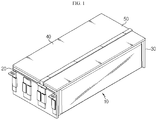
- a conventional ICB assembly includes a front bus bar frame 20 and a rear bus bar frame 30 respectively assembled at a front side and a rear side of a cell stack 10, and a top frame 40 covering an upper portion of the cell stack 10.
- a FPC Flexible Printed Circuit
- a sensing unit 50 for sensing voltage information of battery cells is attached to an upper surface or a lower surface of the top frame 40.
- the battery module may be configured by packaging the ICB assembly and the cell stack with a module case.
- the module case frequently adopts a mono frame having a square tube shape in a hollow structure to improve the energy density.
- the conventional battery module as described above has the following problems.
- the top frame 40 of the conventional ICB assembly has the advantage of protecting the upper portion of the cell stack 10 and the FPC 50, but decreases the width of the cell stack 10 stored in the mono frame as much as the thickness thereof, thereby reducing the energy density of the battery module.
- the present disclosure is directed to providing a battery module, which may allow the ICB assembly to be assembled with the cell stack and the module case excellently.
- a battery module which includes a cell stack having a plurality of battery cells stacked in one direction, and an ICB assembly electrically connected to the plurality of battery cells to sense voltage information
- the ICB assembly includes a front bus bar frame assembled to a front side of the cell stack and a rear bus bar frame assembled to a rear side of the cell stack, the front bus bar frame and the rear bus bar frame respectively having a plurality of bus bars that are in contact with electrode leads of the battery cells; a sensing member assembled such that one side thereof is fixed to the front bus bar frame and the other side thereof is fixed to the rear bus bar frame; and at least one bridge plate connected to the front bus bar frame and the rear bus bar frame to keep a gap between the front bus bar frame and the rear bus bar frame constant.
- the at least one bridge plate may include two bridge plates, and the two bridge plates may be disposed at both side surfaces of the front bus bar frame and the rear bus bar frame one by one.
- At least one of the front bus bar frame and the rear bus bar frame may have a bridge assembling portion formed at a top end of both side surfaces thereof so that an end portion of the bridge plates is hinged thereto.
- the bridge assembling portion may have a hinge shaft formed to protrude from a surface thereof, and the end portion of the bridge plates may have a perforated hole into which the hinge shaft is inserted.
- the hinge shaft may be deformed so that a portion thereof exposing through the perforated hole to an opposite surface of the bridge plate has a greater diameter than the perforated hole.
- the bridge assembling portion may further have a stopper configured to restrict the front bus bar frame and the rear bus bar frame not to rotate over a predetermined angle with respect to the bridge plate based on the hinge shaft.
- the stopper may further include a second stopper surface provided orthogonal to the first stopper surface to contact an upper surface of the end portion of the bridge plate when the angle between the front bus bar frame or the rear bus bar frame and the bridge plate becomes 180 degrees.
- the front bus bar frame and the rear bus bar frame may have slits through which the electrode leads pass forward and rearward, and the slits may be opened to a lower end of the front bus bar frame or the rear bus bar frame.
- the FPC or the FFC may be disposed to pass through a slot perforated in the front bus bar frame and the rear bus bar frame at a location adjacent to and below a top surface thereof.
- a battery module to which an ICB assembly capable of supporting a cell stack with a minimized number of components and capable of increasing the energy density of the cell stack is applied.
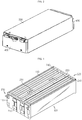
- FIG. 2 is a schematic perspective view showing a battery module according to an embodiment of the present disclosure
- FIG. 3 is a schematic perspective view showing a cell stack and an ICB assembly accommodated in a module case of FIG. 2 .
- a battery module 1 includes a cell stack 100, an ICB assembly 200, a module case 300, and a module cover 400.
- the cell stack 100 may be a collection of a plurality of battery cells 110.
- the battery cell 110 is a pouch-type secondary battery, and though not shown in detail, the battery cell 110 is a bi-directional pouch-type secondary battery in which a positive electrode lead and a negative electrode lead protrude in opposite directions.
- the pouch-type secondary battery may include an electrode assembly, an electrolyte and a pouch exterior.
- the pouch exterior may include two pouches, and a concave inner space may be formed in at least one of the two pouches.
- the electrode assembly may be accommodated in the inner space of the pouch. Sealing portions are provided at outer circumferences of the two pouches, and the sealing portions are welded to each other so that the inner space accommodating the electrode assembly may be sealed.
- a portion of the electrode lead 111 may be fused to the sealing portion of the pouch exterior and the other portion of the electrode lead 111 may extend out of the pouch exterior and be exposed out of the pouch exterior to function as an electrode terminal of the secondary battery.
- the ICB assembly 200 is a component for electrically connecting the plurality of battery cells 110 forming the cell stack 100 and sensing voltage information of the battery cells 110.
- the ICB assembly 200 may include a front bus bar frame 210, a rear bus bar frame 220, a sensing member 230 and a bridge plate 240.
- the front bus bar frame 210 and the rear bus bar frame 220 may be respectively disposed at a front portion and a rear portion of the cell stack 100 and have a plate-like shape for supporting the front portion and the rear portion of the cell stack 100.
- the front bus bar frame 210 and the rear bus bar frame 220 may include a plurality of bus bars disposed at a front surface thereof and slits 212 through formed at a left side and/or a right side thereof based on the bus bars so that the electrode leads 111 pass therethrough.
- each battery cell 110 may be known by connecting a sensing terminal to each bus bar and sensing the voltage thereof.
- the sensed voltage values of the battery cells 110 may be transmitted to a BMS (not shown), and the BMS may control the charge and discharge state of the abnormal battery cells 110 based on the voltage values.
- the FPC 230 employed as the sensing member 230 may be disposed to extend along the longitudinal direction of the cell stack 100 from an upper portion of the cell stack 100. Also, one side of the FPC 230 is fixed to the top end of the front bus bar frame 210 and the other side thereof is fixed to the top end of the rear bus bar frame 220, thereby securing the fixation.
- Two bridge plates 240 are connected to both side surfaces of the top end of the front bus bar frame 210 and the rear bus bar frame 220 one by one so that a gap therebetween is kept constant.
- two bridge plates 240 are coupled to both side surfaces of the front bus bar frame 210 and the rear bus bar frame 220 below the top surface thereof so that the ICB assembly 200 of this embodiment has a smaller width compared to the conventional ICB assembly having the top frame 40 (see FIG. 1 ).
- the ICB assembly 200 of this embodiment has a height reduced by the thickness of at least the top frame 40 compared to the conventional ICB assembly having the top frame 40.
- the width of the battery cells 110 may be increased as much as the space occupied by the top frame 40, so that the cell stack 100 and the ICB assembly 200 are stored in the module case 300 more efficiently, thereby increasing the energy density.
- the hinge coupling structure between the front bus bar frame 210 and the bridge plate 240 is the same as the hinge coupling structure between the rear bus bar frame 220 and the bridge plate 240, the hinge coupling structure between the front bus bar frame 210 and the bridge plate 240 will be described in detail, and the hinge coupling structure between the rear bus bar frame 220 and the bridge plate 240 will not be described in detail.
- the front bus bar frame 210 and the rear bus bar frame 220 respectively include a bridge assembling portions 213 for connecting both end portions 241 of the bridge plate 240 to the top ends of both side surfaces thereof.
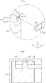
- the bridge assembling portion 213 has a hinge shaft 215 formed to protrude from the surface thereof (in the -Y-axis direction), and the end portion 241 of the bridge plate 240 coupled thereto has a perforated hole 243 having a diameter into which the hinge shaft 215 may be inserted.
- the hinge shaft 215 is fit into the perforated hole 243 as shown in FIG. 7 , and then a head portion of the hinge shaft 215 may be deformed to have a greater diameter than the perforated hole 243 as shown in FIG. 8 so that the end portion 241 of the bridge plate 240 is not separated from the bridge assembling portion 213.
- the hinge shaft 215 may be deformed by forging, hot-melt or spinning.
- a hole may be formed in the surface of the bridge assembling portion 213, and the end portion 241 of the bridge plate 240 may be coupled to the bridge assembling portion 213 using a rivet or a shoulder bolt.
- the ICB assembly 200 may be easily assembled to the cell stack 100.
- the electrode leads 111 of the battery cells 110 should be inserted into the slits 212 of the front bus bar frame 210 and the slits 212 of the rear bus bar frame 220, respectively, and then the portions exposed out of the slits 212 should be welded to the surface of the bus bars.
- the front bus bar frame 210 and the rear bus bar frame 220 are configured to be rotatable relative to the bridge plate 240, the front bus bar frame 210 or the rear bus bar frame 220 may be rotated outward to secure the assembling space, and then the electrode leads 111 may be inserted into the slits 212.
- the front bus bar frame 210 and the rear bus bar frame 220 are rotatable and also the slits 212 are opened to the bottom end of each bus bar frame, it is more convenient to insert the electrode leads 111 into the slits 212.
- the stopper 217 plays a role of restricting the front bus bar frame 210 or the rear bus bar frame 220 to be rotatable within an angle range of 90 degrees to 180 degrees with respect to the bridge plate 240. Accordingly, it is possible to prevent the front bus bar frame 210 or the rear bus bar frame 220 from being erroneously assembled due to excessive rotation or prevent the electrode leads 111 of the battery cells 110 from being damaged.
- the top end of the side surface of the front bus bar frame 210 has a stepped surface of a rectangular area where a portion is recessed (in the +Y-axis direction) than the other portion.
- the hinge shaft 215 is positioned at the center of the recessed stepped surface, and the first stopper surface 217a and the second stopper surface 217b are provided at locations spaced apart from the periphery of the hinge shaft 215.
- the first stopper surface 217a and the second stopper surface 217b may be implemented as walls that are orthogonal to each other and surround two peripheral surfaces of the hinge shaft 215.
- the front bus bar frame 210 is rotatable only in the outward direction.
- the second stopper surface 217b is perpendicular to the first stopper surface 217a and thus contacts the top surface of the end portion 241 of the bridge plate 240 when the angle between the front bus bar frame 210 and the bridge plate 240 is 180 degrees.
- the front bus bar frame 210 is not able to rotate more than 180 degrees with respect to the bridge plate 240.
- the module case 300 is a structure that forms the appearance of the battery module 1 and may be manufactured in a rectangular tube form by, for example, extrusion or die casting. In the module case 300 (see FIG. 2 ), the cell stack 100 and the ICB assembly 200 assembled with each other may be inserted and accommodated.
- the module case 300 may be manufactured to have a size with which the cell stack 100, in which the ICB assembly 200 is assembled, may be fit into the inner space. Since the cell stack 100 may be compressed in the inner space of the module case 300, it is possible to prevent the battery cells 110 from moving and mitigating the swelling phenomenon.
- the module cover 400 may be mounted to a front portion and a rear portion of the module case 300.
- the module cover 400 may be made of an insulating material such as plastic and plays a role of shielding the electrode leads 111 of the battery cells 110 and the bus bars not to be exposed to the outside.
- the front bus bar frame 210 may further include a slot 218 perforated through a plate surface thereof at a position adjacent to and below the top surface.
- the FPC may extend forward and backward of the front bus bar frame 210 through the slot 218.
- the fixed state may be stably maintained even under vibration or shock, compared to the former embodiment.
- the position of the FPC may be lowered below the top surfaces of the front bus bar frame 210 and the rear bus bar frame 220, thereby preventing the FPC from being damaged due to friction with the inner wall of the module case 300 when being accommodated in the module case 300.
- the battery pack according to the present disclosure may be used as an energy source for an electric vehicle such as an electric vehicle and a hybrid electric vehicle, or a power storage device (ESS).
- an electric vehicle such as an electric vehicle and a hybrid electric vehicle, or a power storage device (ESS).
- ESS power storage device
Landscapes
- Chemical & Material Sciences (AREA)
- Chemical Kinetics & Catalysis (AREA)
- Electrochemistry (AREA)
- General Chemical & Material Sciences (AREA)
- Engineering & Computer Science (AREA)
- Manufacturing & Machinery (AREA)
- Physics & Mathematics (AREA)
- General Physics & Mathematics (AREA)
- Microelectronics & Electronic Packaging (AREA)
- Aviation & Aerospace Engineering (AREA)
- Connection Of Batteries Or Terminals (AREA)
- Battery Mounting, Suspending (AREA)
- Secondary Cells (AREA)
Applications Claiming Priority (2)
| Application Number | Priority Date | Filing Date | Title |
|---|---|---|---|
| KR1020180120759A KR102250193B1 (ko) | 2018-10-10 | 2018-10-10 | 공간 절약형 icb 조립체를 적용한 배터리 모듈 |
| PCT/KR2019/012346 WO2020075988A1 (ko) | 2018-10-10 | 2019-09-23 | 공간 절약형 icb 조립체를 적용한 배터리 모듈 |
Publications (3)
| Publication Number | Publication Date |
|---|---|
| EP3828983A1 true EP3828983A1 (de) | 2021-06-02 |
| EP3828983A4 EP3828983A4 (de) | 2022-01-05 |
| EP3828983B1 EP3828983B1 (de) | 2024-02-21 |
Family
ID=70164969
Family Applications (1)
| Application Number | Title | Priority Date | Filing Date |
|---|---|---|---|
| EP19870527.9A Active EP3828983B1 (de) | 2018-10-10 | 2019-09-23 | Batteriemodul mit icb-anordnung in einer platzsparenden struktur |
Country Status (9)
| Country | Link |
|---|---|
| US (1) | US20210313657A1 (de) |
| EP (1) | EP3828983B1 (de) |
| JP (1) | JP7119126B2 (de) |
| KR (1) | KR102250193B1 (de) |
| CN (2) | CN111029516B (de) |
| ES (1) | ES2973853T3 (de) |
| HU (1) | HUE065679T2 (de) |
| PL (1) | PL3828983T3 (de) |
| WO (1) | WO2020075988A1 (de) |
Cited By (2)
| Publication number | Priority date | Publication date | Assignee | Title |
|---|---|---|---|---|
| EP4037062A3 (de) * | 2021-01-12 | 2022-10-12 | SK Innovation Co., Ltd. | Batteriemodul |
| US12476331B2 (en) | 2020-04-22 | 2025-11-18 | Lg Energy Solution, Ltd. | Battery module and battery pack including the same |
Families Citing this family (19)
| Publication number | Priority date | Publication date | Assignee | Title |
|---|---|---|---|---|
| KR102250193B1 (ko) * | 2018-10-10 | 2021-05-07 | 주식회사 엘지화학 | 공간 절약형 icb 조립체를 적용한 배터리 모듈 |
| KR102821825B1 (ko) * | 2020-07-22 | 2025-06-16 | 주식회사 엘지에너지솔루션 | 전극 리드와 전압 센싱부재 간의 연결을 단순화한 배터리 모듈 및 이를 포함하는 배터리 팩 |
| KR102951291B1 (ko) | 2020-07-22 | 2026-04-09 | 주식회사 엘지에너지솔루션 | 전극 리드와 전압 센싱부재 간의 연결을 단순화한 배터리 모듈 및 이를 포함하는 배터리 팩 |
| KR102929045B1 (ko) * | 2020-08-07 | 2026-02-19 | 주식회사 엘지에너지솔루션 | 전지 모듈 및 이를 포함하는 전지 팩 |
| KR20220021439A (ko) * | 2020-08-13 | 2022-02-22 | 주식회사 엘지에너지솔루션 | 개선된 전극 리드 연결 구조를 갖는 배터리 모듈, 그리고 이를 포함하는 배터리 팩 및 자동차 |
| KR20220034466A (ko) | 2020-09-11 | 2022-03-18 | 한국단자공업 주식회사 | 배터리셀 연결장치 및 이를 포함하는 배터리팩 |
| KR102945051B1 (ko) * | 2020-09-22 | 2026-03-26 | 주식회사 엘지에너지솔루션 | 전지 모듈 및 이를 포함하는 전지팩 |
| KR102860571B1 (ko) | 2020-10-14 | 2025-09-15 | 주식회사 엘지에너지솔루션 | 전지 모듈 및 그 제조 방법 |
| KR102848526B1 (ko) * | 2020-10-26 | 2025-08-21 | 주식회사 엘지에너지솔루션 | 배터리 모듈 센싱 유닛, 배터리 모듈, 배터리 팩 및 배터리 모듈 센싱 유닛의 제조방법 |
| KR102866659B1 (ko) * | 2020-11-10 | 2025-09-29 | 주식회사 엘지에너지솔루션 | 전압 센싱 부품들의 조립 구조를 개선한 배터리 모듈 및 이를 포함하는 배터리 팩 |
| KR102735192B1 (ko) * | 2020-11-30 | 2024-11-27 | 삼성에스디아이 주식회사 | 배터리 팩 |
| KR20220075946A (ko) * | 2020-11-30 | 2022-06-08 | 주식회사 엘지에너지솔루션 | 전지 모듈 및 이를 포함하는 전지팩 |
| KR20220120916A (ko) * | 2021-02-24 | 2022-08-31 | 주식회사 엘지에너지솔루션 | 전지 모듈 및 이를 포함하는 전지팩 |
| KR102857910B1 (ko) * | 2021-05-11 | 2025-09-09 | 주식회사 엘지에너지솔루션 | 전지 모듈 및 이를 포함하는 전지 팩 |
| KR102862209B1 (ko) | 2021-06-08 | 2025-09-18 | 주식회사 엘지에너지솔루션 | 절연 냉각액을 이용한 냉각 구조를 갖는 배터리 모듈, 그리고 이를 포함하는 배터리 팩 및 자동차 |
| KR20230046394A (ko) * | 2021-09-30 | 2023-04-06 | 현대자동차주식회사 | 차량용 배터리 방열유닛 및 이를 포함한 차량용 배터리 케이스 |
| KR102872638B1 (ko) * | 2021-11-08 | 2025-10-16 | 주식회사 엘지에너지솔루션 | 배터리 모듈 및 이를 포함한 배터리 팩 |
| CN115149221B (zh) * | 2022-05-17 | 2024-07-16 | 常州长盈精密技术有限公司 | 车用电池包线束 |
| FR3162407A1 (fr) * | 2024-05-21 | 2025-11-28 | Stellantis Auto Sas | Vehicule automobile electrique ou hybride comportant une batterie comprenant une barre d’interconnexion |
Family Cites Families (22)
| Publication number | Priority date | Publication date | Assignee | Title |
|---|---|---|---|---|
| JPS5918236A (ja) * | 1982-07-20 | 1984-01-30 | Yanmar Diesel Engine Co Ltd | 手始動エンジンの液体循環ポンプ |
| JPH04203517A (ja) * | 1990-11-29 | 1992-07-24 | Toshiba Corp | 軸の枢着装置 |
| KR20050032659A (ko) * | 2003-10-02 | 2005-04-08 | 삼성전자주식회사 | 휴대용 컴퓨터 |
| WO2010113455A1 (ja) * | 2009-03-31 | 2010-10-07 | 三洋電機株式会社 | 電池モジュール、バッテリシステムおよび電動車両 |
| CN102379058B (zh) | 2009-04-01 | 2014-06-18 | 株式会社Lg化学 | 电压感测部件和采用该电压感测部件的电池模块 |
| JPWO2011024477A1 (ja) * | 2009-08-31 | 2013-01-24 | 三洋電機株式会社 | バッテリモジュール、バッテリシステムおよび電動車両 |
| JP5535794B2 (ja) * | 2010-06-30 | 2014-07-02 | 三洋電機株式会社 | 組電池 |
| JP6234929B2 (ja) | 2012-08-30 | 2017-11-22 | 三洋電機株式会社 | 電源装置及び電源装置を備える車両並びに蓄電装置、電源装置の製造方 |
| KR101709562B1 (ko) * | 2013-07-31 | 2017-03-08 | 주식회사 엘지화학 | 전지모듈 어셈블리 |
| DE102016206437B4 (de) | 2016-04-15 | 2019-08-14 | Continental Automotive Gmbh | Verfahren zur Regeneration eines Partikelfilters im Abgassystem eines Verbrennungsmotors |
| KR102059612B1 (ko) | 2016-08-24 | 2019-12-26 | 주식회사 엘지화학 | 전지모듈 내에서 공간을 적게 점유하는 상호 연결 부재 및 이를 포함하는 전지모듈 |
| KR102102927B1 (ko) * | 2016-10-06 | 2020-04-21 | 주식회사 엘지화학 | 배터리 모듈, 이러한 배터리 모듈을 포함하는 배터리 팩 및 이러한 배터리 팩을 포함하는 자동차 |
| WO2018124494A2 (ko) | 2016-12-27 | 2018-07-05 | 주식회사 유라코퍼레이션 | 버스바 어셈블리 및 프레임 조립체 |
| KR102033001B1 (ko) * | 2017-02-28 | 2019-10-16 | 주식회사 유라코퍼레이션 | 프레임 조립체, 프레임 조립체의 제조 방법 및 배터리 모듈의 제조 방법 |
| KR101844852B1 (ko) * | 2016-12-30 | 2018-04-03 | 주식회사 유라코퍼레이션 | 배터리셀 모듈의 연성회로기판 고정 구조 |
| WO2018124751A1 (ko) | 2016-12-27 | 2018-07-05 | 주식회사 유라코퍼레이션 | 연성회로기판 및 이를 포함하는 프레임 조립체 |
| KR101829350B1 (ko) | 2016-12-30 | 2018-02-14 | 한국단자공업 주식회사 | 배터리모듈용 센싱장치 |
| KR101928072B1 (ko) * | 2016-12-30 | 2018-12-11 | 주식회사 유라코퍼레이션 | 배터리셀 모듈의 힌지 구조 |
| WO2018159928A1 (ko) * | 2017-02-28 | 2018-09-07 | 주식회사 유라코퍼레이션 | 프레임 조립체 및 이를 제조하기 위한 방법 |
| CN207518008U (zh) * | 2017-11-17 | 2018-06-19 | 微宏动力系统(湖州)有限公司 | 电池汇流排及电池模组 |
| KR101842515B1 (ko) * | 2017-12-11 | 2018-05-14 | 김정연 | 배터리 모듈 케이스 |
| KR102250193B1 (ko) * | 2018-10-10 | 2021-05-07 | 주식회사 엘지화학 | 공간 절약형 icb 조립체를 적용한 배터리 모듈 |
-
2018
- 2018-10-10 KR KR1020180120759A patent/KR102250193B1/ko active Active
-
2019
- 2019-09-23 PL PL19870527.9T patent/PL3828983T3/pl unknown
- 2019-09-23 EP EP19870527.9A patent/EP3828983B1/de active Active
- 2019-09-23 US US17/267,257 patent/US20210313657A1/en active Pending
- 2019-09-23 HU HUE19870527A patent/HUE065679T2/hu unknown
- 2019-09-23 WO PCT/KR2019/012346 patent/WO2020075988A1/ko not_active Ceased
- 2019-09-23 ES ES19870527T patent/ES2973853T3/es active Active
- 2019-09-23 JP JP2020565385A patent/JP7119126B2/ja active Active
- 2019-10-09 CN CN201910954468.7A patent/CN111029516B/zh active Active
- 2019-10-09 CN CN201921684310.4U patent/CN210607431U/zh active Active
Cited By (2)
| Publication number | Priority date | Publication date | Assignee | Title |
|---|---|---|---|---|
| US12476331B2 (en) | 2020-04-22 | 2025-11-18 | Lg Energy Solution, Ltd. | Battery module and battery pack including the same |
| EP4037062A3 (de) * | 2021-01-12 | 2022-10-12 | SK Innovation Co., Ltd. | Batteriemodul |
Also Published As
| Publication number | Publication date |
|---|---|
| CN111029516B (zh) | 2021-04-20 |
| CN111029516A (zh) | 2020-04-17 |
| JP2021525436A (ja) | 2021-09-24 |
| HUE065679T2 (hu) | 2024-06-28 |
| WO2020075988A1 (ko) | 2020-04-16 |
| KR20200040619A (ko) | 2020-04-20 |
| EP3828983B1 (de) | 2024-02-21 |
| EP3828983A4 (de) | 2022-01-05 |
| KR102250193B1 (ko) | 2021-05-07 |
| JP7119126B2 (ja) | 2022-08-16 |
| US20210313657A1 (en) | 2021-10-07 |
| ES2973853T3 (es) | 2024-06-24 |
| PL3828983T3 (pl) | 2024-06-17 |
| CN210607431U (zh) | 2020-05-22 |
Similar Documents
| Publication | Publication Date | Title |
|---|---|---|
| EP3828983B1 (de) | Batteriemodul mit icb-anordnung in einer platzsparenden struktur | |
| CN116349081B (zh) | 电池单体组件以及包括该电池单体组件的电池组和车辆 | |
| JP7045602B2 (ja) | 組立性が向上したバスバーフレームを備えたバッテリーモジュール | |
| JP7084496B2 (ja) | バッテリーモジュール、該バッテリーモジュールを含むバッテリーパック及び該バッテリーパックを含む自動車 | |
| JP7034417B2 (ja) | バッテリーモジュール | |
| KR100863729B1 (ko) | 전지모듈 인터페이스 | |
| KR102301196B1 (ko) | 접속 플레이트를 구비한 배터리 팩 | |
| JP2021501447A (ja) | バッテリーモジュール及びそれを含むバッテリーパック | |
| EP3076456A1 (de) | Batteriemodul und batteriepack damit | |
| EP4053989B1 (de) | Batteriemodul mit stromschiene, batteriepack und fahrzeug | |
| CN112470335A (zh) | 电池模块和包括该电池模块的电池组 | |
| JP7044897B2 (ja) | バッテリーモジュール、該バッテリーモジュールを含むバッテリーパック及び該バッテリーパックを含む自動車 | |
| CN114982056B (zh) | 电池模块、包括该电池模块的电池组和车辆 | |
| EP3154108A1 (de) | Batteriemodul und batteriepack damit | |
| JP2022519501A (ja) | 電池モジュール | |
| KR102321794B1 (ko) | 양방향 체결 구조를 갖는 커넥터를 포함하는 전지 모듈 | |
| EP4456285A1 (de) | Logische zelle, sekundärbatteriemodul und sekundärbatteriepack damit | |
| CN116114104A (zh) | 电池模块、电池组和电力存储装置 | |
| JP7775453B2 (ja) | バッテリーモジュール、バッテリーパック、及びこれを含む自動車 | |
| EP4708508A1 (de) | Batteriepack und fahrzeug damit | |
| KR20250040390A (ko) | 배터리 팩 및 이를 포함하는 자동차 | |
| KR20240009718A (ko) | 배터리 모듈 및 이를 포함하는 배터리 팩 및 자동차 | |
| JP2024508121A (ja) | 安全性が強化されたバッテリーモジュール |
Legal Events
| Date | Code | Title | Description |
|---|---|---|---|
| STAA | Information on the status of an ep patent application or granted ep patent |
Free format text: STATUS: THE INTERNATIONAL PUBLICATION HAS BEEN MADE |
|
| PUAI | Public reference made under article 153(3) epc to a published international application that has entered the european phase |
Free format text: ORIGINAL CODE: 0009012 |
|
| STAA | Information on the status of an ep patent application or granted ep patent |
Free format text: STATUS: REQUEST FOR EXAMINATION WAS MADE |
|
| 17P | Request for examination filed |
Effective date: 20210226 |
|
| AK | Designated contracting states |
Kind code of ref document: A1 Designated state(s): AL AT BE BG CH CY CZ DE DK EE ES FI FR GB GR HR HU IE IS IT LI LT LU LV MC MK MT NL NO PL PT RO RS SE SI SK SM TR |
|
| A4 | Supplementary search report drawn up and despatched |
Effective date: 20211208 |
|
| RIC1 | Information provided on ipc code assigned before grant |
Ipc: H01M 50/502 20210101ALI20211202BHEP Ipc: H01M 50/211 20210101ALI20211202BHEP Ipc: H01M 50/249 20210101ALI20211202BHEP Ipc: H01M 50/519 20210101ALI20211202BHEP Ipc: H05K 7/02 20060101ALI20211202BHEP Ipc: H01M 50/507 20210101ALI20211202BHEP Ipc: H01M 50/284 20210101ALI20211202BHEP Ipc: H01M 50/209 20210101ALI20211202BHEP Ipc: H01M 50/20 20210101ALI20211202BHEP Ipc: G01R 1/04 20060101ALI20211202BHEP Ipc: H01M 10/48 20060101ALI20211202BHEP Ipc: H01M 10/42 20060101AFI20211202BHEP |
|
| DAV | Request for validation of the european patent (deleted) | ||
| DAX | Request for extension of the european patent (deleted) | ||
| RAP1 | Party data changed (applicant data changed or rights of an application transferred) |
Owner name: LG ENERGY SOLUTION LTD. |
|
| RAP3 | Party data changed (applicant data changed or rights of an application transferred) |
Owner name: LG ENERGY SOLUTION, LTD. |
|
| GRAP | Despatch of communication of intention to grant a patent |
Free format text: ORIGINAL CODE: EPIDOSNIGR1 |
|
| STAA | Information on the status of an ep patent application or granted ep patent |
Free format text: STATUS: GRANT OF PATENT IS INTENDED |
|
| RIC1 | Information provided on ipc code assigned before grant |
Ipc: H01M 50/569 20210101ALI20230906BHEP Ipc: H01M 50/503 20210101ALI20230906BHEP Ipc: H01M 50/50 20210101ALI20230906BHEP Ipc: H01M 50/271 20210101ALI20230906BHEP Ipc: G01R 31/364 20190101ALI20230906BHEP Ipc: H01M 10/48 20060101ALI20230906BHEP Ipc: G01R 1/04 20060101ALI20230906BHEP Ipc: H01M 50/20 20210101ALI20230906BHEP Ipc: H01M 50/209 20210101ALI20230906BHEP Ipc: H01M 50/284 20210101ALI20230906BHEP Ipc: H01M 50/507 20210101ALI20230906BHEP Ipc: H05K 7/02 20060101ALI20230906BHEP Ipc: H01M 50/519 20210101ALI20230906BHEP Ipc: H01M 50/249 20210101ALI20230906BHEP Ipc: H01M 50/211 20210101ALI20230906BHEP Ipc: H01M 50/502 20210101ALI20230906BHEP Ipc: H01M 10/42 20060101AFI20230906BHEP |
|
| INTG | Intention to grant announced |
Effective date: 20230920 |
|
| GRAS | Grant fee paid |
Free format text: ORIGINAL CODE: EPIDOSNIGR3 |
|
| GRAA | (expected) grant |
Free format text: ORIGINAL CODE: 0009210 |
|
| STAA | Information on the status of an ep patent application or granted ep patent |
Free format text: STATUS: THE PATENT HAS BEEN GRANTED |
|
| P01 | Opt-out of the competence of the unified patent court (upc) registered |
Effective date: 20240105 |
|
| AK | Designated contracting states |
Kind code of ref document: B1 Designated state(s): AL AT BE BG CH CY CZ DE DK EE ES FI FR GB GR HR HU IE IS IT LI LT LU LV MC MK MT NL NO PL PT RO RS SE SI SK SM TR |
|
| REG | Reference to a national code |
Ref country code: GB Ref legal event code: FG4D |
|
| REG | Reference to a national code |
Ref country code: CH Ref legal event code: EP |
|
| REG | Reference to a national code |
Ref country code: IE Ref legal event code: FG4D |
|
| REG | Reference to a national code |
Ref country code: DE Ref legal event code: R096 Ref document number: 602019047080 Country of ref document: DE |
|
| REG | Reference to a national code |
Ref country code: NL Ref legal event code: FP |
|
| REG | Reference to a national code |
Ref country code: SE Ref legal event code: TRGR |
|
| REG | Reference to a national code |
Ref country code: LT Ref legal event code: MG9D |
|
| REG | Reference to a national code |
Ref country code: ES Ref legal event code: FG2A Ref document number: 2973853 Country of ref document: ES Kind code of ref document: T3 Effective date: 20240624 |
|
| REG | Reference to a national code |
Ref country code: HU Ref legal event code: AG4A Ref document number: E065679 Country of ref document: HU |
|
| PG25 | Lapsed in a contracting state [announced via postgrant information from national office to epo] |
Ref country code: IS Free format text: LAPSE BECAUSE OF FAILURE TO SUBMIT A TRANSLATION OF THE DESCRIPTION OR TO PAY THE FEE WITHIN THE PRESCRIBED TIME-LIMIT Effective date: 20240621 |
|
| PG25 | Lapsed in a contracting state [announced via postgrant information from national office to epo] |
Ref country code: LT Free format text: LAPSE BECAUSE OF FAILURE TO SUBMIT A TRANSLATION OF THE DESCRIPTION OR TO PAY THE FEE WITHIN THE PRESCRIBED TIME-LIMIT Effective date: 20240221 |
|
| PG25 | Lapsed in a contracting state [announced via postgrant information from national office to epo] |
Ref country code: GR Free format text: LAPSE BECAUSE OF FAILURE TO SUBMIT A TRANSLATION OF THE DESCRIPTION OR TO PAY THE FEE WITHIN THE PRESCRIBED TIME-LIMIT Effective date: 20240522 |
|
| REG | Reference to a national code |
Ref country code: AT Ref legal event code: MK05 Ref document number: 1659905 Country of ref document: AT Kind code of ref document: T Effective date: 20240221 |
|
| PG25 | Lapsed in a contracting state [announced via postgrant information from national office to epo] |
Ref country code: HR Free format text: LAPSE BECAUSE OF FAILURE TO SUBMIT A TRANSLATION OF THE DESCRIPTION OR TO PAY THE FEE WITHIN THE PRESCRIBED TIME-LIMIT Effective date: 20240221 Ref country code: RS Free format text: LAPSE BECAUSE OF FAILURE TO SUBMIT A TRANSLATION OF THE DESCRIPTION OR TO PAY THE FEE WITHIN THE PRESCRIBED TIME-LIMIT Effective date: 20240521 |
|
| PG25 | Lapsed in a contracting state [announced via postgrant information from national office to epo] |
Ref country code: AT Free format text: LAPSE BECAUSE OF FAILURE TO SUBMIT A TRANSLATION OF THE DESCRIPTION OR TO PAY THE FEE WITHIN THE PRESCRIBED TIME-LIMIT Effective date: 20240221 |
|
| PG25 | Lapsed in a contracting state [announced via postgrant information from national office to epo] |
Ref country code: RS Free format text: LAPSE BECAUSE OF FAILURE TO SUBMIT A TRANSLATION OF THE DESCRIPTION OR TO PAY THE FEE WITHIN THE PRESCRIBED TIME-LIMIT Effective date: 20240521 Ref country code: NO Free format text: LAPSE BECAUSE OF FAILURE TO SUBMIT A TRANSLATION OF THE DESCRIPTION OR TO PAY THE FEE WITHIN THE PRESCRIBED TIME-LIMIT Effective date: 20240521 Ref country code: LT Free format text: LAPSE BECAUSE OF FAILURE TO SUBMIT A TRANSLATION OF THE DESCRIPTION OR TO PAY THE FEE WITHIN THE PRESCRIBED TIME-LIMIT Effective date: 20240221 Ref country code: IS Free format text: LAPSE BECAUSE OF FAILURE TO SUBMIT A TRANSLATION OF THE DESCRIPTION OR TO PAY THE FEE WITHIN THE PRESCRIBED TIME-LIMIT Effective date: 20240621 Ref country code: HR Free format text: LAPSE BECAUSE OF FAILURE TO SUBMIT A TRANSLATION OF THE DESCRIPTION OR TO PAY THE FEE WITHIN THE PRESCRIBED TIME-LIMIT Effective date: 20240221 Ref country code: GR Free format text: LAPSE BECAUSE OF FAILURE TO SUBMIT A TRANSLATION OF THE DESCRIPTION OR TO PAY THE FEE WITHIN THE PRESCRIBED TIME-LIMIT Effective date: 20240522 Ref country code: FI Free format text: LAPSE BECAUSE OF FAILURE TO SUBMIT A TRANSLATION OF THE DESCRIPTION OR TO PAY THE FEE WITHIN THE PRESCRIBED TIME-LIMIT Effective date: 20240221 Ref country code: BG Free format text: LAPSE BECAUSE OF FAILURE TO SUBMIT A TRANSLATION OF THE DESCRIPTION OR TO PAY THE FEE WITHIN THE PRESCRIBED TIME-LIMIT Effective date: 20240221 Ref country code: AT Free format text: LAPSE BECAUSE OF FAILURE TO SUBMIT A TRANSLATION OF THE DESCRIPTION OR TO PAY THE FEE WITHIN THE PRESCRIBED TIME-LIMIT Effective date: 20240221 |
|
| PG25 | Lapsed in a contracting state [announced via postgrant information from national office to epo] |
Ref country code: PT Free format text: LAPSE BECAUSE OF FAILURE TO SUBMIT A TRANSLATION OF THE DESCRIPTION OR TO PAY THE FEE WITHIN THE PRESCRIBED TIME-LIMIT Effective date: 20240621 |
|
| PG25 | Lapsed in a contracting state [announced via postgrant information from national office to epo] |
Ref country code: PT Free format text: LAPSE BECAUSE OF FAILURE TO SUBMIT A TRANSLATION OF THE DESCRIPTION OR TO PAY THE FEE WITHIN THE PRESCRIBED TIME-LIMIT Effective date: 20240621 Ref country code: LV Free format text: LAPSE BECAUSE OF FAILURE TO SUBMIT A TRANSLATION OF THE DESCRIPTION OR TO PAY THE FEE WITHIN THE PRESCRIBED TIME-LIMIT Effective date: 20240221 |
|
| PG25 | Lapsed in a contracting state [announced via postgrant information from national office to epo] |
Ref country code: DK Free format text: LAPSE BECAUSE OF FAILURE TO SUBMIT A TRANSLATION OF THE DESCRIPTION OR TO PAY THE FEE WITHIN THE PRESCRIBED TIME-LIMIT Effective date: 20240221 |
|
| PG25 | Lapsed in a contracting state [announced via postgrant information from national office to epo] |
Ref country code: SM Free format text: LAPSE BECAUSE OF FAILURE TO SUBMIT A TRANSLATION OF THE DESCRIPTION OR TO PAY THE FEE WITHIN THE PRESCRIBED TIME-LIMIT Effective date: 20240221 |
|
| PG25 | Lapsed in a contracting state [announced via postgrant information from national office to epo] |
Ref country code: CZ Free format text: LAPSE BECAUSE OF FAILURE TO SUBMIT A TRANSLATION OF THE DESCRIPTION OR TO PAY THE FEE WITHIN THE PRESCRIBED TIME-LIMIT Effective date: 20240221 Ref country code: EE Free format text: LAPSE BECAUSE OF FAILURE TO SUBMIT A TRANSLATION OF THE DESCRIPTION OR TO PAY THE FEE WITHIN THE PRESCRIBED TIME-LIMIT Effective date: 20240221 |
|
| PG25 | Lapsed in a contracting state [announced via postgrant information from national office to epo] |
Ref country code: SK Free format text: LAPSE BECAUSE OF FAILURE TO SUBMIT A TRANSLATION OF THE DESCRIPTION OR TO PAY THE FEE WITHIN THE PRESCRIBED TIME-LIMIT Effective date: 20240221 |
|
| PG25 | Lapsed in a contracting state [announced via postgrant information from national office to epo] |
Ref country code: SM Free format text: LAPSE BECAUSE OF FAILURE TO SUBMIT A TRANSLATION OF THE DESCRIPTION OR TO PAY THE FEE WITHIN THE PRESCRIBED TIME-LIMIT Effective date: 20240221 Ref country code: SK Free format text: LAPSE BECAUSE OF FAILURE TO SUBMIT A TRANSLATION OF THE DESCRIPTION OR TO PAY THE FEE WITHIN THE PRESCRIBED TIME-LIMIT Effective date: 20240221 Ref country code: RO Free format text: LAPSE BECAUSE OF FAILURE TO SUBMIT A TRANSLATION OF THE DESCRIPTION OR TO PAY THE FEE WITHIN THE PRESCRIBED TIME-LIMIT Effective date: 20240221 Ref country code: EE Free format text: LAPSE BECAUSE OF FAILURE TO SUBMIT A TRANSLATION OF THE DESCRIPTION OR TO PAY THE FEE WITHIN THE PRESCRIBED TIME-LIMIT Effective date: 20240221 Ref country code: DK Free format text: LAPSE BECAUSE OF FAILURE TO SUBMIT A TRANSLATION OF THE DESCRIPTION OR TO PAY THE FEE WITHIN THE PRESCRIBED TIME-LIMIT Effective date: 20240221 Ref country code: CZ Free format text: LAPSE BECAUSE OF FAILURE TO SUBMIT A TRANSLATION OF THE DESCRIPTION OR TO PAY THE FEE WITHIN THE PRESCRIBED TIME-LIMIT Effective date: 20240221 |
|
| REG | Reference to a national code |
Ref country code: DE Ref legal event code: R097 Ref document number: 602019047080 Country of ref document: DE |
|
| PLBE | No opposition filed within time limit |
Free format text: ORIGINAL CODE: 0009261 |
|
| STAA | Information on the status of an ep patent application or granted ep patent |
Free format text: STATUS: NO OPPOSITION FILED WITHIN TIME LIMIT |
|
| 26N | No opposition filed |
Effective date: 20241122 |
|
| PG25 | Lapsed in a contracting state [announced via postgrant information from national office to epo] |
Ref country code: SI Free format text: LAPSE BECAUSE OF FAILURE TO SUBMIT A TRANSLATION OF THE DESCRIPTION OR TO PAY THE FEE WITHIN THE PRESCRIBED TIME-LIMIT Effective date: 20240221 Ref country code: MC Free format text: LAPSE BECAUSE OF FAILURE TO SUBMIT A TRANSLATION OF THE DESCRIPTION OR TO PAY THE FEE WITHIN THE PRESCRIBED TIME-LIMIT Effective date: 20240221 |
|
| REG | Reference to a national code |
Ref country code: CH Ref legal event code: PL |
|
| PG25 | Lapsed in a contracting state [announced via postgrant information from national office to epo] |
Ref country code: LU Free format text: LAPSE BECAUSE OF NON-PAYMENT OF DUE FEES Effective date: 20240923 |
|
| PG25 | Lapsed in a contracting state [announced via postgrant information from national office to epo] |
Ref country code: CH Free format text: LAPSE BECAUSE OF NON-PAYMENT OF DUE FEES Effective date: 20240930 |
|
| PG25 | Lapsed in a contracting state [announced via postgrant information from national office to epo] |
Ref country code: IE Free format text: LAPSE BECAUSE OF NON-PAYMENT OF DUE FEES Effective date: 20240923 |
|
| PGFP | Annual fee paid to national office [announced via postgrant information from national office to epo] |
Ref country code: NL Payment date: 20250821 Year of fee payment: 7 |
|
| PGFP | Annual fee paid to national office [announced via postgrant information from national office to epo] |
Ref country code: DE Payment date: 20250820 Year of fee payment: 7 |
|
| PGFP | Annual fee paid to national office [announced via postgrant information from national office to epo] |
Ref country code: TR Payment date: 20250822 Year of fee payment: 7 Ref country code: PL Payment date: 20250822 Year of fee payment: 7 Ref country code: IT Payment date: 20250822 Year of fee payment: 7 |
|
| PGFP | Annual fee paid to national office [announced via postgrant information from national office to epo] |
Ref country code: HU Payment date: 20250929 Year of fee payment: 7 Ref country code: BE Payment date: 20250820 Year of fee payment: 7 Ref country code: GB Payment date: 20250820 Year of fee payment: 7 |
|
| PGFP | Annual fee paid to national office [announced via postgrant information from national office to epo] |
Ref country code: FR Payment date: 20250821 Year of fee payment: 7 |
|
| PGFP | Annual fee paid to national office [announced via postgrant information from national office to epo] |
Ref country code: SE Payment date: 20250821 Year of fee payment: 7 |
|
| PG25 | Lapsed in a contracting state [announced via postgrant information from national office to epo] |
Ref country code: CY Free format text: LAPSE BECAUSE OF FAILURE TO SUBMIT A TRANSLATION OF THE DESCRIPTION OR TO PAY THE FEE WITHIN THE PRESCRIBED TIME-LIMIT; INVALID AB INITIO Effective date: 20190923 |
|
| PGFP | Annual fee paid to national office [announced via postgrant information from national office to epo] |
Ref country code: ES Payment date: 20251007 Year of fee payment: 7 |