EP3829009A1 - Boîtier destiné à recevoir un premier élément de connexion enfichable et un second élément de connexion enfichable - Google Patents
Boîtier destiné à recevoir un premier élément de connexion enfichable et un second élément de connexion enfichable Download PDFInfo
- Publication number
- EP3829009A1 EP3829009A1 EP19211507.9A EP19211507A EP3829009A1 EP 3829009 A1 EP3829009 A1 EP 3829009A1 EP 19211507 A EP19211507 A EP 19211507A EP 3829009 A1 EP3829009 A1 EP 3829009A1
- Authority
- EP
- European Patent Office
- Prior art keywords
- housing
- inner housing
- longitudinal direction
- plug
- plug connection
- Prior art date
- Legal status (The legal status is an assumption and is not a legal conclusion. Google has not performed a legal analysis and makes no representation as to the accuracy of the status listed.)
- Withdrawn
Links
- 238000007789 sealing Methods 0.000 claims description 39
- 230000008878 coupling Effects 0.000 claims description 4
- 238000010168 coupling process Methods 0.000 claims description 4
- 238000005859 coupling reaction Methods 0.000 claims description 4
- 238000006073 displacement reaction Methods 0.000 claims description 3
- 238000011161 development Methods 0.000 description 12
- 230000018109 developmental process Effects 0.000 description 12
- 239000004020 conductor Substances 0.000 description 10
- 230000008901 benefit Effects 0.000 description 5
- 229920000106 Liquid crystal polymer Polymers 0.000 description 4
- 239000004977 Liquid-crystal polymers (LCPs) Substances 0.000 description 4
- 150000001875 compounds Chemical class 0.000 description 4
- XLYOFNOQVPJJNP-UHFFFAOYSA-N water Substances O XLYOFNOQVPJJNP-UHFFFAOYSA-N 0.000 description 4
- 229910000906 Bronze Inorganic materials 0.000 description 3
- 239000004734 Polyphenylene sulfide Substances 0.000 description 3
- 239000010974 bronze Substances 0.000 description 3
- KUNSUQLRTQLHQQ-UHFFFAOYSA-N copper tin Chemical compound [Cu].[Sn] KUNSUQLRTQLHQQ-UHFFFAOYSA-N 0.000 description 3
- 238000013461 design Methods 0.000 description 3
- 229920000069 polyphenylene sulfide Polymers 0.000 description 3
- 238000000926 separation method Methods 0.000 description 3
- 229910001220 stainless steel Inorganic materials 0.000 description 3
- 239000010935 stainless steel Substances 0.000 description 3
- 229920002943 EPDM rubber Polymers 0.000 description 2
- 229930040373 Paraformaldehyde Natural products 0.000 description 2
- 239000000463 material Substances 0.000 description 2
- 239000002184 metal Substances 0.000 description 2
- 229910052751 metal Inorganic materials 0.000 description 2
- 229920006324 polyoxymethylene Polymers 0.000 description 2
- 238000005476 soldering Methods 0.000 description 2
- 229910001369 Brass Inorganic materials 0.000 description 1
- 230000032683 aging Effects 0.000 description 1
- 229910052782 aluminium Inorganic materials 0.000 description 1
- XAGFODPZIPBFFR-UHFFFAOYSA-N aluminium Chemical compound [Al] XAGFODPZIPBFFR-UHFFFAOYSA-N 0.000 description 1
- 230000004888 barrier function Effects 0.000 description 1
- 239000010951 brass Substances 0.000 description 1
- 238000005266 casting Methods 0.000 description 1
- 238000006243 chemical reaction Methods 0.000 description 1
- 238000002788 crimping Methods 0.000 description 1
- 229920001973 fluoroelastomer Polymers 0.000 description 1
- 230000001771 impaired effect Effects 0.000 description 1
- 239000000314 lubricant Substances 0.000 description 1
- 238000012423 maintenance Methods 0.000 description 1
- 238000004519 manufacturing process Methods 0.000 description 1
- 230000003287 optical effect Effects 0.000 description 1
- 230000035515 penetration Effects 0.000 description 1
- 239000004033 plastic Substances 0.000 description 1
- -1 polyoxymethylene Polymers 0.000 description 1
- 239000011347 resin Substances 0.000 description 1
- 229920005989 resin Polymers 0.000 description 1
- 239000007787 solid Substances 0.000 description 1
- 229920001169 thermoplastic Polymers 0.000 description 1
- 239000004416 thermosoftening plastic Substances 0.000 description 1
- 238000012546 transfer Methods 0.000 description 1
- 238000003466 welding Methods 0.000 description 1
Images


Classifications
-
- H—ELECTRICITY
- H01—ELECTRIC ELEMENTS
- H01R—ELECTRICALLY-CONDUCTIVE CONNECTIONS; STRUCTURAL ASSOCIATIONS OF A PLURALITY OF MUTUALLY-INSULATED ELECTRICAL CONNECTING ELEMENTS; COUPLING DEVICES; CURRENT COLLECTORS
- H01R24/00—Two-part coupling devices, or either of their cooperating parts, characterised by their overall structure
- H01R24/20—Coupling parts carrying sockets, clips or analogous contacts and secured only to wire or cable
-
- H—ELECTRICITY
- H01—ELECTRIC ELEMENTS
- H01R—ELECTRICALLY-CONDUCTIVE CONNECTIONS; STRUCTURAL ASSOCIATIONS OF A PLURALITY OF MUTUALLY-INSULATED ELECTRICAL CONNECTING ELEMENTS; COUPLING DEVICES; CURRENT COLLECTORS
- H01R13/00—Details of coupling devices of the kinds covered by groups H01R12/70 or H01R24/00 - H01R33/00
- H01R13/46—Bases; Cases
- H01R13/502—Bases; Cases composed of different pieces
-
- F—MECHANICAL ENGINEERING; LIGHTING; HEATING; WEAPONS; BLASTING
- F21—LIGHTING
- F21V—FUNCTIONAL FEATURES OR DETAILS OF LIGHTING DEVICES OR SYSTEMS THEREOF; STRUCTURAL COMBINATIONS OF LIGHTING DEVICES WITH OTHER ARTICLES, NOT OTHERWISE PROVIDED FOR
- F21V17/00—Fastening of component parts of lighting devices, e.g. shades, globes, refractors, reflectors, filters, screens, grids or protective cages
- F21V17/10—Fastening of component parts of lighting devices, e.g. shades, globes, refractors, reflectors, filters, screens, grids or protective cages characterised by specific fastening means or way of fastening
- F21V17/12—Fastening of component parts of lighting devices, e.g. shades, globes, refractors, reflectors, filters, screens, grids or protective cages characterised by specific fastening means or way of fastening by screwing
-
- F—MECHANICAL ENGINEERING; LIGHTING; HEATING; WEAPONS; BLASTING
- F21—LIGHTING
- F21V—FUNCTIONAL FEATURES OR DETAILS OF LIGHTING DEVICES OR SYSTEMS THEREOF; STRUCTURAL COMBINATIONS OF LIGHTING DEVICES WITH OTHER ARTICLES, NOT OTHERWISE PROVIDED FOR
- F21V23/00—Arrangement of electric circuit elements in or on lighting devices
- F21V23/06—Arrangement of electric circuit elements in or on lighting devices the elements being coupling devices, e.g. connectors
-
- F—MECHANICAL ENGINEERING; LIGHTING; HEATING; WEAPONS; BLASTING
- F21—LIGHTING
- F21V—FUNCTIONAL FEATURES OR DETAILS OF LIGHTING DEVICES OR SYSTEMS THEREOF; STRUCTURAL COMBINATIONS OF LIGHTING DEVICES WITH OTHER ARTICLES, NOT OTHERWISE PROVIDED FOR
- F21V31/00—Gas-tight or water-tight arrangements
-
- H—ELECTRICITY
- H01—ELECTRIC ELEMENTS
- H01R—ELECTRICALLY-CONDUCTIVE CONNECTIONS; STRUCTURAL ASSOCIATIONS OF A PLURALITY OF MUTUALLY-INSULATED ELECTRICAL CONNECTING ELEMENTS; COUPLING DEVICES; CURRENT COLLECTORS
- H01R13/00—Details of coupling devices of the kinds covered by groups H01R12/70 or H01R24/00 - H01R33/00
- H01R13/46—Bases; Cases
- H01R13/52—Dustproof, splashproof, drip-proof, waterproof, or flameproof cases
-
- H—ELECTRICITY
- H01—ELECTRIC ELEMENTS
- H01R—ELECTRICALLY-CONDUCTIVE CONNECTIONS; STRUCTURAL ASSOCIATIONS OF A PLURALITY OF MUTUALLY-INSULATED ELECTRICAL CONNECTING ELEMENTS; COUPLING DEVICES; CURRENT COLLECTORS
- H01R13/00—Details of coupling devices of the kinds covered by groups H01R12/70 or H01R24/00 - H01R33/00
- H01R13/46—Bases; Cases
- H01R13/52—Dustproof, splashproof, drip-proof, waterproof, or flameproof cases
- H01R13/5202—Sealing means between parts of housing or between housing part and a wall, e.g. sealing rings
-
- H—ELECTRICITY
- H01—ELECTRIC ELEMENTS
- H01R—ELECTRICALLY-CONDUCTIVE CONNECTIONS; STRUCTURAL ASSOCIATIONS OF A PLURALITY OF MUTUALLY-INSULATED ELECTRICAL CONNECTING ELEMENTS; COUPLING DEVICES; CURRENT COLLECTORS
- H01R13/00—Details of coupling devices of the kinds covered by groups H01R12/70 or H01R24/00 - H01R33/00
- H01R13/46—Bases; Cases
- H01R13/52—Dustproof, splashproof, drip-proof, waterproof, or flameproof cases
- H01R13/5213—Covers
-
- H—ELECTRICITY
- H01—ELECTRIC ELEMENTS
- H01R—ELECTRICALLY-CONDUCTIVE CONNECTIONS; STRUCTURAL ASSOCIATIONS OF A PLURALITY OF MUTUALLY-INSULATED ELECTRICAL CONNECTING ELEMENTS; COUPLING DEVICES; CURRENT COLLECTORS
- H01R13/00—Details of coupling devices of the kinds covered by groups H01R12/70 or H01R24/00 - H01R33/00
- H01R13/62—Means for facilitating engagement or disengagement of coupling parts or for holding them in engagement
- H01R13/622—Screw-ring or screw-casing
-
- H—ELECTRICITY
- H01—ELECTRIC ELEMENTS
- H01R—ELECTRICALLY-CONDUCTIVE CONNECTIONS; STRUCTURAL ASSOCIATIONS OF A PLURALITY OF MUTUALLY-INSULATED ELECTRICAL CONNECTING ELEMENTS; COUPLING DEVICES; CURRENT COLLECTORS
- H01R24/00—Two-part coupling devices, or either of their cooperating parts, characterised by their overall structure
-
- H—ELECTRICITY
- H01—ELECTRIC ELEMENTS
- H01R—ELECTRICALLY-CONDUCTIVE CONNECTIONS; STRUCTURAL ASSOCIATIONS OF A PLURALITY OF MUTUALLY-INSULATED ELECTRICAL CONNECTING ELEMENTS; COUPLING DEVICES; CURRENT COLLECTORS
- H01R24/00—Two-part coupling devices, or either of their cooperating parts, characterised by their overall structure
- H01R24/66—Two-part coupling devices, or either of their cooperating parts, characterised by their overall structure with pins, blades or analogous contacts and secured to apparatus or structure, e.g. to a wall
-
- H—ELECTRICITY
- H01—ELECTRIC ELEMENTS
- H01R—ELECTRICALLY-CONDUCTIVE CONNECTIONS; STRUCTURAL ASSOCIATIONS OF A PLURALITY OF MUTUALLY-INSULATED ELECTRICAL CONNECTING ELEMENTS; COUPLING DEVICES; CURRENT COLLECTORS
- H01R13/00—Details of coupling devices of the kinds covered by groups H01R12/70 or H01R24/00 - H01R33/00
- H01R13/64—Means for preventing incorrect coupling
-
- H—ELECTRICITY
- H01—ELECTRIC ELEMENTS
- H01R—ELECTRICALLY-CONDUCTIVE CONNECTIONS; STRUCTURAL ASSOCIATIONS OF A PLURALITY OF MUTUALLY-INSULATED ELECTRICAL CONNECTING ELEMENTS; COUPLING DEVICES; CURRENT COLLECTORS
- H01R2107/00—Four or more poles
Definitions
- the present invention relates to a housing for receiving a first plug connection element and a second plug connection element and in particular to a housing for the water-protected connection of a plug to a socket.
- a disadvantage of such systems is that the relative movement of the surfaces, which is difficult to control by hand, can lead to wedging of the surfaces or an inclination of these surfaces to one another due to the necessary elasticity of the sealing elements, which leads to a definable or controllable assembly or a definable or controllable Disassembly of the system can make it difficult.
- a further disadvantage of such systems is that an increased expenditure of force may be required when assembling or disassembling.
- the object of the present invention is to provide a housing and supplementary elements for a waterproof system for electrical connector elements that enable a function-preserving assembly and a function-preserving disassembly of the system.
- the idea on which the present invention is based is to enable a stable relative movement of the surfaces provided with sealing elements by means of an intermediate element.
- the invention provides a housing for receiving a first plug connection element and a second plug connection element, with first, second and third interior sections, which are opposite to a longitudinal direction of the housing, which points from the third interior section to the first interior section, one behind the other, the first interior section being designed in this way is to receive the first connector element in the longitudinal direction watertight and to limit a movement of the connector element in the longitudinal direction from a certain point, and the third interior section is designed to an inner housing which is designed to receive the second connector element and a movement of the second connector element opposite to the longitudinal direction, to be received in the longitudinal direction in a watertight manner and movable to and fro, such that the second connector element by sliding the inner housing in in the longitudinal direction in the second interior section can be coupled to the first plug-in connection element; and a first portion of a sliding element, which is configured in a region of an open end of the third interior portion, which is an end of the housing opposite to the longitudinal direction, to over a second portion of the Sliding element to go into engagement with
- the invention further provides an inner housing for a plug connection element to be received in the above-described housing, the third portion of the sliding element on the outer surface in a region of an end of the inner housing which is an end of the inner housing opposite to the longitudinal direction.
- the invention also provides a plug connection system with the above-described housing and the above-described inner housing.
- One advantage of the invention is that a controlled relative movement is achieved between surfaces provided with sealing elements.
- the second section of the sliding element has a nut.
- One advantage of this preferred development of the invention is that a simple mechanical component is used to achieve a controlled movement when coupling connector elements.
- the third section of the displacement element has a first stop for striking the nut in the longitudinal direction away from the one end of the inner housing on the outer surface of the inner housing.
- the third section of the sliding element has a releasable second stop at one end of the inner housing for securing the nut on the inner housing.
- One advantage of this preferred development of the invention is that the nut is secured in a simple manner on the inner housing.
- Another advantage of this preferred development of the invention is that the releasable second stop achieves a controlled movement when the plug-in connection elements are decoupled.
- a first sealing element is provided between the housing and the inner housing.
- the plug connection elements are electrical plug connection elements and the first interior section is designed to accommodate an electrical lighting means for electrical connection to the first plug connection element.
- One advantage of this preferred further development of the invention is that a waterproof and maintenance-friendly housing for lighting means is realized.
- a second sealing element is provided between the housing and the second inner housing.
- the plug connection system is provided with an element which is designed in such a way as to enable the first plug connection element to be properly coupled to the second plug connection element.
- FIG. 13 shows a plan view and a sectional view along a line II-II 'in FIG Fig. 1 a plug / socket system 1 according to a first embodiment of the present invention for use in an electric lamp.
- the plug / socket system 1 has an outer housing 2, a plug 4, a socket 6, an inner housing 8 in which the socket 6 is received, and a union nut 10.
- the outer housing 2 which can also be referred to here as the lamp housing, extends along a longitudinal axis of the same, which defines a longitudinal direction 12, has a cross-section that is essentially symmetrical about the longitudinal axis in a radial direction and encloses a hollow interior.
- the interior is in Fig. 2 divided into an interior section 16 on the connection side, a central interior section 18 and an interior section 20 on the supply side.
- a lamp connection area 22 which widens radially outward in a beam direction, for connecting an electrical lamp (not shown).
- the luminaire can be accommodated completely or partially in the luminaire connection area 22 or be located outside the same.
- the plug 4 which is symmetrical about the longitudinal axis, has a cylinder-shaped connection-side part, shown in a simplified manner, which has a first diameter and which protrudes into the lamp connection area 22.
- the connection-side part is preferably provided with an anti-rotation device, not shown, which z. B. has an elongated hole provided. From the connection-side part protrude electrically insulated electrical conductors 24, which were connected to electrical contacts (not shown) of the plug 4 at common connection points, preferably by soldering or crimping.
- the electrical conductors 24 are used to electrically connect the electrical lamp, not shown.
- connection-side part towards a supply-side end of the plug 4, a groove 26 for receiving an optional securing ring (not shown) for securing the plug 4 from falling out of the outer housing 2 is also formed.
- the plug 4 also has a cylindrical central part which has a second diameter which is greater than the first diameter of the connection-side part.
- a circumferential projection 28 is formed between the connection-side part and the central part, which projection is used for mechanical engagement with a projection 29 on an inner surface of the outer housing 2.
- the middle part of the plug 4 has in an outer surface thereof a further groove 30 for receiving a sealing ring 31 surrounding the plug 4 in the polar direction.
- the sealing ring 31 is preferably an O-ring with a circular cross-section and is used to separate the interior section 16 on the connection side from the central Separate interior section 18 watertight.
- the connector 4 has at the supply-side end of the same in the central interior section 18 a supply-side part from which contact pins 32, preferably four contact pins, inserted into the connector 14 protrude and which has an outer circumferential projection 34 with a variable radial cross section for mechanical coupling with the Has socket 6.
- the projection 34 has a cross-section with a first constant radial thickness and in a supply-side section 38 has a cross-section which in a predominant part has a second radial thickness that is smaller than the first radial thickness, and in the remainder Part has a thickness that increases from the second radial to the first radial thickness ( Fig. 3 ).
- the longitudinal axis symmetrical socket 6 has at a connection-side end thereof a cylindrical connection-side part which complements the shape of the plug 4 in the connection-side section 36 of the projection 34 or has a negative shape.
- the connection-side part has contact sockets inserted into socket 6, into which contact pins 32 are inserted.
- a connection-side central part 40 of the socket 6 is enclosed by a connection-side part of the inner housing 8 which has a circumferential projection 42 which has a shape that complements the shape of the circumferential projection 34.
- the socket 6 Opposite to the longitudinal direction 12, the socket 6 has a hollow central part 44 on the supply side, through which electrical conductors 46, which correspond to the electrical conductors 24 of the plug 4, run in the longitudinal direction 12.
- the contact sockets of the socket 6 are connected to the electrical conductors 46 at common connection points, preferably by soldering.
- a supply-side part 48 of the socket 6 or an electrical line 49 connected to it ( Fig. 6 ) jumps at one end of the plug / socket system on the supply side 1 emerges from the inner housing 8.
- a connection-side middle part of the inner housing 8 encloses with a radial inner surface of the same the supply-side middle part 44 of the socket 6.
- In a radial outer surface of the inner housing 8 in the connection-side middle part of the same in the longitudinal direction 12 further successive grooves 50 for receiving two of the inner housing 8 in the polar direction enclosing sealing rings 52 formed.
- the sealing rings 52 are preferably O-rings with a circular cross section and serve to separate the central interior section 18 from the supply-side part of the supply-side interior section 20 in a watertight manner.
- a shoulder 54 as a mechanical stop for the union nut 10 is formed by a middle part of the inner housing 8 on the supply side, which has a larger diameter in the radial direction than the middle part on the connection side.
- a supply-side part of the inner housing 8 is designed to accommodate the union nut 10 along the longitudinal axis of the size of the union nut 10 and has a reduced diameter compared to the connection-side middle part and the supply-side middle part of the inner housing 8.
- a further groove 56 for receiving a locking ring 58 for the union nut 10 is formed.
- the outer housing 2 has in the vicinity of the supply-side end of the plug / socket system 1 in a part of the supply-side interior section 20, which has a larger inner diameter than the majority of the supply-side interior section 20 and the central interior section 18, on an inner surface of the outer housing 2 a circumferential projection 59 and an internal thread 60 which fits to an external thread 62 on an outer surface of the union nut 10.
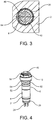
- FIG. 13 is a sectional view taken along a line III-III 'in FIG Fig. 2 of the plug / socket system 1 according to the first embodiment of the invention.
- Fig. 3 particularly shows the varying radial thickness of the supply-side portion 38 of the FIG Fig. 2 projection 34 shown.
- the supply-side section 38 is shaped in such a way that a segment 64-like part 64 is formed.
- the circumferential projection 42 of the connection-side part of the inner housing 8 ( Fig. 2 ) has a suitable form in this area.
- the design of the projections 34 and 42 ensures a proper connection of the plug 4 and the socket 6 accommodated in the inner housing 8 when the plug / socket system 1 is assembled.
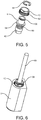
- FIG. 11 shows a perspective view of the plug / socket system 1 according to the first embodiment of the invention without the outer housing 2.
- Fig. 5 shows a perspective exploded view of the inner housing 8, the union nut 10 and the locking ring 58 of the plug / socket system 1 according to the first embodiment of the invention.
- Fig. 6 shows a perspective view of the assembled plug / socket system 1 according to the first embodiment of the invention with the electrical line 49 emerging therefrom.
- Fig. 7 shows a perspective view of a plug / socket system 1 'according to a second embodiment of the present invention for use in a plug connection between two electrical lines.
- An outer housing 2 'of the plug / socket system 1' has three cylindrical housing sections 66, 68 and 70 which follow one another in the longitudinal direction 12 and which decrease in a radial direction towards the connection-side end of the plug / socket system 1 ' Have diameter.
- the housing sections 66, 68 and 70 are connected to one another by ramp-like sections.
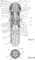
- FIG. 13 shows a plan view and a sectional view along a line IX-IX 'in FIG Fig. 8 of the plug-socket system 1 'according to the second embodiment of the present invention.
- the outer housing 2 'does not have a widening lamp connection area 22 in the connection-side interior section 16 at the connection-side end of the plug / socket system 1', so that the Outer housing 2 ′ has a reduced volume compared to outer housing 2.
- an electrical line 72 which has the electrical conductors 24, is connected to the plug 4 in a line connection area of the connection-side interior section 16.
- FIG. 13 is a sectional view taken along a line XX 'in FIG Fig. 9 of the plug / socket system 1 'according to the second embodiment of the invention with the modified outer housing 2'.
- the plug 4 together with the sealing ring 31 inserted into the groove 30 is first inserted into the outer housing 2, 2' until the circumferential projection 28 with the projection 29 of the outer housing 2, 2 'introduced.
- the union nut 10 is then placed on the shoulder 54 of the inner housing 8 and then secured with the locking ring 58 by sliding the locking ring 58 radially into the groove 56.
- the bush 6 is pushed into the inner housing 8 until it abuts the circumferential projection 42, and the inner housing 8 is then inserted into the outer housing 2 together with the bush 6 and the sealing rings 52 inserted into the grooves 50 until the external thread 62 the union nut 10 meets the internal thread 60 of the outer housing 2.
- the inner housing 8 together with the socket 6 is pushed into the outer housing 2, 2 'in a controlled manner, until the inner housing 8 with the shoulder 54 on the projection 59 of the inner surface of the outer housing 2, 2' in the interior section 20 on the connection side strikes, and the union nut 10 is tightened.
- the union nut 10 thus pushes the electrical contact sockets of the socket 6 longitudinally axially into position and secures the plug 4 and the inner housing 8 against unintentional pulling out.
- the union nut 10 enables a comfortable introduction of force via side surfaces of the same spaced apart by a suitable wrench size and also provides protection, such as protection against mechanical damage or a sealing barrier for the sealing rings 52.
- the locking ring 58 is used for the separation mentioned above mainly to transfer the loosening force of the union nut 10 to the inner housing 8 and securely pull the socket 6 off the plug 4 and pull it out of the outer housing 2, 2 'by preventing the sealing rings 52 from sticking through a controlled loosening movement. Such sticking etc.
- the locking ring 58 also serves to secure the union nut 10 against loss during assembly and disassembly.
- the plug / socket systems 1 and 1 ' have an integrated water stop function, with which the penetration of moisture into the coupling area between plug 4 and socket 6 and into the lamp connection area 22 in Fig. 2 or to the electrical line 72 in Fig. 9 is avoided. Therefore, for example, the lamp connection area 22 is not impaired or opened by pulling the socket 6 out of the outer housing 2, 2 '.
- the plug 4 On a first sealing plane in the first interior section 16, the plug 4 is fastened with the sealing ring 31 in the outer housing 2, 2 '.
- the connection points between the electrical conductors 24 and the electrical contacts (not shown) of the plug 4 are preferably additionally encapsulated with a sealing compound in the connection-side interior section 16, in the first embodiment the lamp connection area 22, which forms an additional water stop.
- the sealing ring 31 then also serves to prevent the sealing compound from entering, for example, the lamp connection area 22 into the central interior section 18.
- connection points of the contact sockets of the socket 6 with the electrical conductors 46 are preferably also encapsulated with a sealing compound, which forms a water stop of the electrical conductors 46 and a strain relief of a line having the electrical conductors 46.
- the two sealing rings 52 form a seal between the outer housing 2 and the inner housing 8. This third sealing level protects the plug / socket connection in the central interior area 18.
- the plug 4, the inner housing 8 and the socket 106 are preferably made of polyphenylene sulfide (PPS).
- the union nut 10 and the locking ring 58 are preferably also made of PPS.
- the locking ring 58 is preferably a locking ring according to DIN 471.
- the outer housing 2 is preferably in one piece, is made by casting and consists of bronze.
- the sealing rings 30 and 52 are preferably made of ethylene-propylene-diene rubber (EPDM).
- EPDM ethylene-propylene-diene rubber
- the sealing compound on the first and the second sealing level preferably consists of 2-component cast resin.
- the first embodiment is preferably used in a luminaire with a degree of protection with high requirements, such as an underwater luminaire, a pond luminaire or a recessed floor luminaire.
- a luminaire with a degree of protection with high requirements such as an underwater luminaire, a pond luminaire or a recessed floor luminaire.
- the lighting means is preferably at least one LED.
- the light source is preferably operated with a direct voltage of 24V for underwater lights or 48V for recessed floor lights or with an alternating voltage of 230V if a voltage conversion takes place in the light.
- the contact pins 32 and the corresponding contact sockets in the socket 6 preferably have a circular cross section in the longitudinal direction 12.
- the outer housing 2, 2 ′ can have a cross-section which is not symmetrical about the longitudinal axis or any other desired shape within the scope of the principles of the invention.
- the inner housing 8 may have any other known and suitable shape.
- the grooves 30 and / or 50 for the sealing rings 31 and / or 52 are in alternative embodiments in the outer housing 2, 2 'or both in the plug 4 and the inner housing 8 and in the outer housing 2, 2' or once in an inner one Element, such as the plug 4 and the inner housing 8, and once formed in the outer housing 2, 2 '.
- the sealing rings 31 and 52 and / or grooves 30 and 50 have a different cross section in alternative embodiments, or the grooves 30 and 50 and the sealing rings 31 and 52 are replaced by a different sealing principle.
- the union nut 10 and / or the locking ring 58 consist of another thermoplastic or another plastic, such as polyoxymethylene (POM), or a Metal, such as stainless steel or bronze.
- the outer housing 2 consists alternatively of stainless steel or aluminum and / or can be constructed from several parts with, for example, different manufacturing methods and from different materials. These parts can be interconnected, e.g. B. by welding.
- the sealing rings 31 and 52 alternatively consist of fluororubber (FKM).
- a locking washer in accordance with DIN 6799 or another standard part is provided instead of the locking ring 56.
- a union nut 10 with a suitable width across flats instead of a union nut 10 with a suitable width across flats, a knurled nut, which enables a comfortable introduction of force, or another suitable and known screw element is provided.
- the plug and the socket instead of four poles have a different number of poles, such as. B. two poles, have round pins made of solid metal pins, such. B. brass pins, and / or the connectors use a cylindrical elastic socket.
- the contact pins 32 and the corresponding contact sockets in the socket 6 have a rectangular or other conventional and suitable cross section in the longitudinal direction 12.
- the invention is used under different electrical operating conditions with different operating voltages and operating currents.
- the invention is used for optical plug connections, such as for light guides, instead of electrical plug connections.
Landscapes
- Engineering & Computer Science (AREA)
- General Engineering & Computer Science (AREA)
- Connector Housings Or Holding Contact Members (AREA)
Priority Applications (2)
| Application Number | Priority Date | Filing Date | Title |
|---|---|---|---|
| EP19211507.9A EP3829009A1 (fr) | 2019-11-26 | 2019-11-26 | Boîtier destiné à recevoir un premier élément de connexion enfichable et un second élément de connexion enfichable |
| CN202010149681.3A CN112952443A (zh) | 2019-11-26 | 2020-03-06 | 用于容纳第一插塞连接元件和第二插塞连接元件的壳体 |
Applications Claiming Priority (1)
| Application Number | Priority Date | Filing Date | Title |
|---|---|---|---|
| EP19211507.9A EP3829009A1 (fr) | 2019-11-26 | 2019-11-26 | Boîtier destiné à recevoir un premier élément de connexion enfichable et un second élément de connexion enfichable |
Publications (1)
| Publication Number | Publication Date |
|---|---|
| EP3829009A1 true EP3829009A1 (fr) | 2021-06-02 |
Family
ID=68696347
Family Applications (1)
| Application Number | Title | Priority Date | Filing Date |
|---|---|---|---|
| EP19211507.9A Withdrawn EP3829009A1 (fr) | 2019-11-26 | 2019-11-26 | Boîtier destiné à recevoir un premier élément de connexion enfichable et un second élément de connexion enfichable |
Country Status (2)
| Country | Link |
|---|---|
| EP (1) | EP3829009A1 (fr) |
| CN (1) | CN112952443A (fr) |
Families Citing this family (1)
| Publication number | Priority date | Publication date | Assignee | Title |
|---|---|---|---|---|
| CN210430179U (zh) * | 2019-08-15 | 2020-04-28 | 东莞富强电子有限公司 | 电动车插座连接器装置 |
Citations (5)
| Publication number | Priority date | Publication date | Assignee | Title |
|---|---|---|---|---|
| DE29509854U1 (de) * | 1995-06-17 | 1995-08-17 | Festo AG & Co, 73734 Esslingen | Elektrische Steckverbindungseinrichtung |
| DE10058265C1 (de) * | 2000-11-23 | 2002-06-13 | Dbt Automation Gmbh Essen | Kabelstecker für elektrische Kabelverbindungen |
| US20040157499A1 (en) * | 2003-02-07 | 2004-08-12 | Hypertronics Corporation | Connecting device |
| US9722350B1 (en) * | 2016-11-14 | 2017-08-01 | Amphenol Corporation | Connector terminal and method of assembling the same |
| US10454207B1 (en) * | 2018-09-17 | 2019-10-22 | Sung Guen Eun | Packing member for waterproof electric connector |
-
2019
- 2019-11-26 EP EP19211507.9A patent/EP3829009A1/fr not_active Withdrawn
-
2020
- 2020-03-06 CN CN202010149681.3A patent/CN112952443A/zh active Pending
Patent Citations (5)
| Publication number | Priority date | Publication date | Assignee | Title |
|---|---|---|---|---|
| DE29509854U1 (de) * | 1995-06-17 | 1995-08-17 | Festo AG & Co, 73734 Esslingen | Elektrische Steckverbindungseinrichtung |
| DE10058265C1 (de) * | 2000-11-23 | 2002-06-13 | Dbt Automation Gmbh Essen | Kabelstecker für elektrische Kabelverbindungen |
| US20040157499A1 (en) * | 2003-02-07 | 2004-08-12 | Hypertronics Corporation | Connecting device |
| US9722350B1 (en) * | 2016-11-14 | 2017-08-01 | Amphenol Corporation | Connector terminal and method of assembling the same |
| US10454207B1 (en) * | 2018-09-17 | 2019-10-22 | Sung Guen Eun | Packing member for waterproof electric connector |
Also Published As
| Publication number | Publication date |
|---|---|
| CN112952443A (zh) | 2021-06-11 |
Similar Documents
| Publication | Publication Date | Title |
|---|---|---|
| DE10332298B4 (de) | Wasserdichter Druckkontakt-Steckverbinder, Kontaktelement für einen wasserdichten Druckkontakt-Steckverbinder und Verfahren zur Herstellung eines Kontaktelements | |
| DE10332325A1 (de) | Druckkontakt-Steckverbinder | |
| DE20302872U1 (de) | Flexible Leuchte mit Magneteinrichtung | |
| DE1465233A1 (de) | Hochspannungssteckverbindungen | |
| DE2215757C3 (de) | Stecker- bzw. Buchsenteil einer Steckvorrichtung für Koaxialkabel | |
| DE4239648A1 (de) | Steckverbindungseinrichtung für Kabel | |
| EP1332313B1 (fr) | Raccord pour conduites flexibles en plastique, comportant un systeme de capteurs | |
| DE112006000446T5 (de) | Umwandlungsadapterring für ein Verbinderelement sowie Verbinderelement | |
| DE10334655A1 (de) | Steckverbindervorrichtung für Kleinservomotoren | |
| DE10258689B3 (de) | Koaxiale Steckverbindung | |
| EP1317021B1 (fr) | Connecteur, conduit pour fluides et installation fluidique | |
| EP3949032A1 (fr) | Système de vissage de fiche | |
| DE202019105182U1 (de) | Steckkupplung für eine Leuchte | |
| DE4224673C2 (de) | Kabelstecker | |
| WO2015085992A1 (fr) | Connecteur à isolation individuelle des conducteurs avec dispositif antitraction | |
| DE20209254U1 (de) | Taschenlampe mit einer Verbindungseinrichtung zum Verbinden von Lampenkontakten einer Lampeneinheit mit einem Gehäuse und einer Batterieeinheit | |
| DE3538193C2 (fr) | ||
| EP0459250B1 (fr) | Garniture d'extrémité de câble | |
| DE29614501U1 (de) | Steckverbindung für elektronische Geräte u.dgl., insbesondere für Geräte im Untertagebergbau | |
| EP1524732A1 (fr) | Connecteur électrique | |
| DE102005048248A1 (de) | Abschlussstecker für Antennenanlagen | |
| WO2020125991A1 (fr) | Connecteur électrique enfichable | |
| EP0236923A2 (fr) | Installation de distribution d'énergie électrique pour des avions | |
| DE102016000384A1 (de) | Mehrpoliger elektrischer Verbinder | |
| DE4135390C1 (en) | Current connecting plug for power supply - has rotatable fixing ring on housing allowing connection to housing of cooperating socket |
Legal Events
| Date | Code | Title | Description |
|---|---|---|---|
| PUAI | Public reference made under article 153(3) epc to a published international application that has entered the european phase |
Free format text: ORIGINAL CODE: 0009012 |
|
| STAA | Information on the status of an ep patent application or granted ep patent |
Free format text: STATUS: REQUEST FOR EXAMINATION WAS MADE |
|
| 17P | Request for examination filed |
Effective date: 20191126 |
|
| AK | Designated contracting states |
Kind code of ref document: A1 Designated state(s): AL AT BE BG CH CY CZ DE DK EE ES FI FR GB GR HR HU IE IS IT LI LT LU LV MC MK MT NL NO PL PT RO RS SE SI SK SM TR |
|
| STAA | Information on the status of an ep patent application or granted ep patent |
Free format text: STATUS: THE APPLICATION IS DEEMED TO BE WITHDRAWN |
|
| 18D | Application deemed to be withdrawn |
Effective date: 20211203 |