EP3829519B1 - Anschlussvorrichtung zum anschluss eines behälters an eine flasche - Google Patents
Anschlussvorrichtung zum anschluss eines behälters an eine flasche Download PDFInfo
- Publication number
- EP3829519B1 EP3829519B1 EP19759648.9A EP19759648A EP3829519B1 EP 3829519 B1 EP3829519 B1 EP 3829519B1 EP 19759648 A EP19759648 A EP 19759648A EP 3829519 B1 EP3829519 B1 EP 3829519B1
- Authority
- EP
- European Patent Office
- Prior art keywords
- connecting device
- perforation
- protective cap
- end piece
- coupling end
- Prior art date
- Legal status (The legal status is an assumption and is not a legal conclusion. Google has not performed a legal analysis and makes no representation as to the accuracy of the status listed.)
- Active
Links
Images


Classifications
-
- A—HUMAN NECESSITIES
- A61—MEDICAL OR VETERINARY SCIENCE; HYGIENE
- A61J—CONTAINERS SPECIALLY ADAPTED FOR MEDICAL OR PHARMACEUTICAL PURPOSES; DEVICES OR METHODS SPECIALLY ADAPTED FOR BRINGING PHARMACEUTICAL PRODUCTS INTO PARTICULAR PHYSICAL OR ADMINISTERING FORMS; DEVICES FOR ADMINISTERING FOOD OR MEDICINES ORALLY; BABY COMFORTERS; DEVICES FOR RECEIVING SPITTLE
- A61J1/00—Containers specially adapted for medical or pharmaceutical purposes
- A61J1/14—Details; Accessories therefor
- A61J1/20—Arrangements for transferring or mixing fluids, e.g. from vial to syringe
- A61J1/2096—Combination of a vial and a syringe for transferring or mixing their contents
-
- A—HUMAN NECESSITIES
- A61—MEDICAL OR VETERINARY SCIENCE; HYGIENE
- A61J—CONTAINERS SPECIALLY ADAPTED FOR MEDICAL OR PHARMACEUTICAL PURPOSES; DEVICES OR METHODS SPECIALLY ADAPTED FOR BRINGING PHARMACEUTICAL PRODUCTS INTO PARTICULAR PHYSICAL OR ADMINISTERING FORMS; DEVICES FOR ADMINISTERING FOOD OR MEDICINES ORALLY; BABY COMFORTERS; DEVICES FOR RECEIVING SPITTLE
- A61J1/00—Containers specially adapted for medical or pharmaceutical purposes
- A61J1/14—Details; Accessories therefor
- A61J1/1412—Containers with closing means, e.g. caps
-
- A—HUMAN NECESSITIES
- A61—MEDICAL OR VETERINARY SCIENCE; HYGIENE
- A61J—CONTAINERS SPECIALLY ADAPTED FOR MEDICAL OR PHARMACEUTICAL PURPOSES; DEVICES OR METHODS SPECIALLY ADAPTED FOR BRINGING PHARMACEUTICAL PRODUCTS INTO PARTICULAR PHYSICAL OR ADMINISTERING FORMS; DEVICES FOR ADMINISTERING FOOD OR MEDICINES ORALLY; BABY COMFORTERS; DEVICES FOR RECEIVING SPITTLE
- A61J1/00—Containers specially adapted for medical or pharmaceutical purposes
- A61J1/14—Details; Accessories therefor
- A61J1/20—Arrangements for transferring or mixing fluids, e.g. from vial to syringe
- A61J1/2003—Accessories used in combination with means for transfer or mixing of fluids, e.g. for activating fluid flow, separating fluids, filtering fluid or venting
- A61J1/2048—Connecting means
-
- A—HUMAN NECESSITIES
- A61—MEDICAL OR VETERINARY SCIENCE; HYGIENE
- A61J—CONTAINERS SPECIALLY ADAPTED FOR MEDICAL OR PHARMACEUTICAL PURPOSES; DEVICES OR METHODS SPECIALLY ADAPTED FOR BRINGING PHARMACEUTICAL PRODUCTS INTO PARTICULAR PHYSICAL OR ADMINISTERING FORMS; DEVICES FOR ADMINISTERING FOOD OR MEDICINES ORALLY; BABY COMFORTERS; DEVICES FOR RECEIVING SPITTLE
- A61J1/00—Containers specially adapted for medical or pharmaceutical purposes
- A61J1/14—Details; Accessories therefor
- A61J1/20—Arrangements for transferring or mixing fluids, e.g. from vial to syringe
- A61J1/2003—Accessories used in combination with means for transfer or mixing of fluids, e.g. for activating fluid flow, separating fluids, filtering fluid or venting
- A61J1/2048—Connecting means
- A61J1/2051—Connecting means having tap means, e.g. tap means activated by sliding
-
- A—HUMAN NECESSITIES
- A61—MEDICAL OR VETERINARY SCIENCE; HYGIENE
- A61J—CONTAINERS SPECIALLY ADAPTED FOR MEDICAL OR PHARMACEUTICAL PURPOSES; DEVICES OR METHODS SPECIALLY ADAPTED FOR BRINGING PHARMACEUTICAL PRODUCTS INTO PARTICULAR PHYSICAL OR ADMINISTERING FORMS; DEVICES FOR ADMINISTERING FOOD OR MEDICINES ORALLY; BABY COMFORTERS; DEVICES FOR RECEIVING SPITTLE
- A61J1/00—Containers specially adapted for medical or pharmaceutical purposes
- A61J1/14—Details; Accessories therefor
- A61J1/20—Arrangements for transferring or mixing fluids, e.g. from vial to syringe
- A61J1/2003—Accessories used in combination with means for transfer or mixing of fluids, e.g. for activating fluid flow, separating fluids, filtering fluid or venting
- A61J1/2079—Filtering means
- A61J1/2082—Filtering means for gas filtration
-
- A—HUMAN NECESSITIES
- A61—MEDICAL OR VETERINARY SCIENCE; HYGIENE
- A61J—CONTAINERS SPECIALLY ADAPTED FOR MEDICAL OR PHARMACEUTICAL PURPOSES; DEVICES OR METHODS SPECIALLY ADAPTED FOR BRINGING PHARMACEUTICAL PRODUCTS INTO PARTICULAR PHYSICAL OR ADMINISTERING FORMS; DEVICES FOR ADMINISTERING FOOD OR MEDICINES ORALLY; BABY COMFORTERS; DEVICES FOR RECEIVING SPITTLE
- A61J1/00—Containers specially adapted for medical or pharmaceutical purposes
- A61J1/14—Details; Accessories therefor
- A61J1/20—Arrangements for transferring or mixing fluids, e.g. from vial to syringe
- A61J1/2003—Accessories used in combination with means for transfer or mixing of fluids, e.g. for activating fluid flow, separating fluids, filtering fluid or venting
- A61J1/2006—Piercing means
- A61J1/201—Piercing means having one piercing end
-
- A—HUMAN NECESSITIES
- A61—MEDICAL OR VETERINARY SCIENCE; HYGIENE
- A61J—CONTAINERS SPECIALLY ADAPTED FOR MEDICAL OR PHARMACEUTICAL PURPOSES; DEVICES OR METHODS SPECIALLY ADAPTED FOR BRINGING PHARMACEUTICAL PRODUCTS INTO PARTICULAR PHYSICAL OR ADMINISTERING FORMS; DEVICES FOR ADMINISTERING FOOD OR MEDICINES ORALLY; BABY COMFORTERS; DEVICES FOR RECEIVING SPITTLE
- A61J1/00—Containers specially adapted for medical or pharmaceutical purposes
- A61J1/14—Details; Accessories therefor
- A61J1/20—Arrangements for transferring or mixing fluids, e.g. from vial to syringe
- A61J1/2003—Accessories used in combination with means for transfer or mixing of fluids, e.g. for activating fluid flow, separating fluids, filtering fluid or venting
- A61J1/2048—Connecting means
- A61J1/2055—Connecting means having gripping means
Definitions
- the present invention relates to a connection device configured to connect a container comprising a male connection tip to a bottle comprising a bottle body equipped with a neck sealed in a sealed manner by a perforable closing element.
- connection device makes it possible to easily connect a container, such as a syringe, to a bottle containing a product to be administered to a patient, and thus to quickly and easily withdraw a predetermined quantity of the contents of the bottle.
- a container such as a syringe
- the request for patent WO 98/32411 A1 describes such a connection device.
- connection device and in particular of the female connection end of the latter, can prove complex, or even impossible, due to the fact that the protective cap is generally fixed in a sealed manner on the part disassembly.
- connection device is generally sterilized after its assembly on the bottle, which further complicates the sterilization step of this assembly.
- connection device it is thus sometimes necessary to carry out the step of assembling the connection device and/or the step of fixing the latter on a bottle in an aseptic manner, which considerably increases the costs of manufacturing a bottle equipped with such a connection device.
- aseptic assembly of the connection device on a bottle is riskier from a quality point of view. microbiological of the product contained in the bottle, which can be harmful to the patient.
- the present invention aims to remedy all or part of these drawbacks.
- connection device which is simple and economical in structure, while allowing optimal sterilization and at lower costs of the connection device.
- connection device makes it possible in particular to expose the female connection tip to a sterilizing gas, such as water vapor or ethylene oxide, and therefore effectively sterilize the connection device.
- a sterilizing gas such as water vapor or ethylene oxide
- Such a configuration of the closing membrane allows the latter not to harm the circulation of a sterilizing gas through the connection device and therefore the sterilization of the connection device using such a gas.
- the connection device according to the present invention can, however, also be effectively sterilized by irradiation with gamma or beta rays.
- the closing membrane prevents the penetration of impurities into the internal chamber via the at least one passage orifice and therefore guarantees the sterility of the female connection tip after the sterilization step of the latter, including when storing and/or handling the connecting device.
- the bottle to which the connection device is intended to be connected, may be a bottle commonly used to contain a product to be administered to a patient and be equipped with a perforable closing element commonly used for close such a bottle, or perhaps a specific bottle equipped with a specific perforable closing element.
- connection device is intended to be fixed in an Add-on manner on a commonly used or specific bottle equipped with a commonly used or specific perforable sealing element.
- connection device may also have one or more of the following characteristics, taken alone or in combination.
- the perforation element is movable between the rest position and the perforation position in a direction of movement substantially parallel to the longitudinal axis of the connection device.
- the closure membrane is impermeable to microorganisms.
- the closure membrane completely covers the at least one passage orifice.
- the closure membrane covers in a tight manner, and preferably in a fluid-tight manner, the at least one passage orifice.
- the closure membrane is impermeable to the fluid, and in particular to gas and/or liquid.
- the closure membrane is located upstream of the at least one passage orifice with respect to a direction of circulation of the sterilization gas through the connection device.
- the closure membrane is made of Tyvek (registered trademark) or of porous paper and permeable to a sterilization gas.
- the at least one passage orifice is provided on the protective cap.
- the closure membrane is fixed on the protective cap, for example by heat sealing.
- the closure membrane is substantially planar.
- the at least one passage orifice opens into the internal chamber facing an annular volume delimited at least partially by the protective cap and the female connection end.
- the protection device comprises a plurality of passage orifices distributed, and for example regularly distributed, around a longitudinal axis of the connection device.
- connection device further comprises a guide part configured to guide, for example in translation, the perforation element during movement of the perforation element from the position of rest towards the perforation position.
- the perforation element extends inside the guide part.
- the perforation element is connected to the guide part by at least one flexible connecting element.
- the connection device comprises locking means configured to lock the perforation element in the rest position.
- the blocking means comprise a first blocking element provided on the perforation element, and a second blocking element provided on the guide part and configured to cooperate with the first blocking element so as to block the perforation element in the rest position.
- the first blocking element can for example be an annular blocking rib and the second blocking element can for example be an annular blocking groove.
- the annular locking rib is provided on an external surface of the perforation element and extends around a longitudinal axis of the perforation element.
- the guide part comprises a guide sleeve having a generally cylindrical shape.
- the female connection tip is provided on a proximal end portion of the perforation element.
- the female connection tip is provided on a proximal end portion of the guide part.
- the female connection tip and the perforation element are configured such that a connection of a male connection element to the female connection element automatically results in a movement of the perforating element from the rest position to the perforating position.
- the protective cap is mounted movable relative to the mounting part between a first protective position in which the protective cap is distant from the mounting part and a second protective position in in which the protective cap is brought closer to the mounting part, the protective cap and the perforation element being configured such that a movement of the protective cap from the first protective position to the second protective position automatically results in a movement of the perforation element from the rest position to the perforation position.
- the mounting part comprises a hooking ring comprising hooking lugs which are distributed angularly around a longitudinal axis of the connection device and which are elastically deformable at least in one direction radial, the hooking lugs being able to cooperate with an annular bead provided on the bottle body so as to fix the connection device to the bottle body.
- the mounting part further comprises a locking ring mounted sliding relative to the hooking ring between a release position in which the hooking tabs are able to be elastically deformed according to a radial and outward direction, and a locking position in which the locking ring extends around the hook tabs and secures the hook tabs in a hook position in which the hook tabs cooperate with the annular bead provided on the body of the bottle.
- the locking ring and the hooking ring are mounted sealed relative to each other.
- the locking ring is coaxial with the hooking ring.
- the guide part is coaxial with the hooking ring.
- connection device comprises retaining means configured to retain the locking ring in the locking position.
- the retaining means comprise a retaining element, such as an annular retaining rib or an annular retaining bead, provided on the locking ring and configured to cooperate, for example by snap-fastening , with the latching ring when the locking ring is in the locking position.
- the retaining element is configured to cooperate with a lower end face of the hooking ring.
- the retaining means comprise an internal thread provided on an internal surface of the locking ring, and an external thread provided on an external surface of the hooking ring and configured to cooperate with the internal thread provided on the locking ring.
- the guide part and the locking ring are in one piece.
- the guide part and the hooking ring are in one piece.
- the protective cap is mounted removably, and preferably fluid-tight, on the mounting part.
- the protective cap can, for example, be removably mounted on the locking ring
- the protective cap is removably mounted on the guide part.
- the protective cap is configured to be screwed onto the mounting part, and for example onto the guide part.
- the protective cap comprises a bottom wall and a side skirt extending from the bottom wall.
- the at least one passage orifice is provided on the protective cap.
- connection device further comprises a tamper-evident ring connected to the protective cap by a plurality of breakable elements.
- the tamper-evident ring is connected to the side skirt by the plurality of breakable elements.
- connection device comprises at least one retaining member, such as a retaining collar, the tamper-evident ring being configured to cooperate with the at least one retaining member during 'removal of the protective cap.
- the at least one retaining member is provided on the mounting part, and for example on the locking ring, or on the guide part.
- the side skirt comprises a first fixing element configured to cooperate, for example by screwing, tightening or snapping, with a second fixing element provided on the mounting part.
- the female connection tip is a female Luer connection tip.
- the container comprising the male connection tip is for example a syringe, such as an empty syringe or a pre-filled syringe, or even a bottle or an administration bag.
- the perforation element extends at least partially into the internal chamber.
- the mounting part is configured to exert pressure on the perforable closing element, and in particular to compress the perforable closing element, so as to produce a watertight assembly, and preferably fluid-tight, of the mounting part on the bottle body.
- the mounting part comprises a support rib configured to bear in a tight manner, and preferably in a fluid-tight manner, on the perforable closing element when the mounting part is mounted on the bottle body.
- the perforation element is mounted in a sealed manner, and preferably in a fluid-tight manner, relative to the guide part.
- connection device is provided with a system (filter, vent) facilitating removal of the contents of the bottle.
- connection device comprises a filtration chamber and the perforation element further comprises a ventilation channel which is configured to fluidly connect the filtration chamber with the internal volume of the bottle body when the perforation element is in the perforation position.
- connection device comprises at least one air filter which is arranged upstream of the ventilation channel.
- the at least one air filter is permeable to air and impermeable to microorganisms.
- the at least one air filter is fixed to the perforation element and is configured to filter the air which comes from outside the connection device and which is intended to flow through the vent channel.
- the protective cap is configured such that removal of the protective cap, for example by unscrewing or loosening or unclipping, automatically causes a movement of the perforation element from the position rest at the perforation position.
- connection device comprises first guide means configured to guide the perforation element relative to the guide part in a helical movement towards the mounting part during a removal of the protective cap, and more particularly when unscrewing the protective cap.
- connection device comprises second guide means configured to guide the perforation element relative to the protective cap in a longitudinal movement towards the mounting part during removal of the protective cap, and more particularly when unscrewing the protective cap.
- the closure membrane is located outside the path of movement of the perforation element from the rest position to the perforation position.
- the perforation element is not configured to perforate the closure membrane.
- the closure membrane is located at a distance from the distal end portion of the perforation element, and for example opposite the distal end portion of the element. perforation, when the perforation element is in the rest position.
- the closure membrane is configured to be located at a distance from the bottle body and the perforable closing element when the connection device is mounted on the bottle body.
- the neck of the bottle body includes an annular bead.
- the bottle body contains a product to be administered to a patient, such as a medicinal solution, a solvent, or any other fluid that can be administered to a patient, or even a gas or a solid, such as a powder and in particular a freeze-dried product.
- a product can for example be a component of a pharmaceutical preparation, such as for example its active ingredient.
- the administration system further comprises a container comprising a male connection tip intended to be connected to the female connection tip of the connection device.
- the container is a pre-filled syringe, an empty syringe, a bottle or an administration bag.
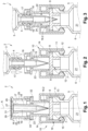
- connection device 2 comprises a mounting part 10 configured to be mounted, in a fluid-tight manner, on the bottle body 6, and more particularly on the neck 7.
- the mounting part 10 is more particularly configured to compress or tighten the perforable closing element 9 so as to achieve a fluid-tight assembly of the mounting part 10 on the bottle body 6.
- the mounting part 10 comprises a hooking ring 11 comprising hooking lugs 12 which are distributed angularly around a longitudinal axis A of the connection device 2 and which are elastically deformable in a radial direction.
- Each hooking tab 12 is more particularly elastically deformable between a deformed position in which said hooking tab 12 is deformed radially outwards so as to allow mounting of the hooking ring 11 on the neck 7 of the bottle, and a hooking position in which said hooking tab 12 is able to cooperate with an annular bead 13 provided on the neck 7 of the bottle 5 so as to fix the connection device 2 to the neck 7.
- the mounting part 10 further comprises a locking ring 14 which is coaxial with the hooking ring 11 and which extends around the hooking ring 11.
- the locking ring 14 is slidably mounted relative to the hooking ring 11, in a sliding direction substantially parallel to the longitudinal axis A, between a release position (not shown in the figures) in which the locking ring 14 is offset axially relative to the hooking tabs 12 and the hooking tabs 12 are capable of being elastically deformed in their deformed positions, and a locking position (visible on the figures 1 to 3 ) in which the locking ring 14 extends around the hooking tabs 12 and immobilizes the latter in their hooking positions.
- connection device 2 comprises retaining means configured to retain the locking ring 14 in the locking position.
- the retaining means may comprise for example an internal thread provided on an internal surface 15 of the locking ring 14, and an external thread provided on an external surface 16 of the hooking ring 11 and configured to cooperate with the internal thread provided on the locking ring 14.
- connection device 2 also includes a female connection tip 17, for example a female Luer connection tip, intended to be connected to the male connection tip 4 of the container 3.
- a female connection tip 17 for example a female Luer connection tip
- connection device 2 further comprises a perforation element 18 which comprises a proximal end portion 18.1, a distal end portion 18.2 opposite the proximal end portion 18.1, and a connecting channel 19 extending over the entire length of the perforation element 18.
- the distal end portion 18.2 is pointed and is configured to perforate the perforable obturation element 9.
- the female connection tip 17 is provided on the proximal end portion 18.2 of the perforation element 18.
- the perforation element 18 is movable, for example in translation and in a direction of movement parallel to the longitudinal axis A of the connection device 2, between a rest position (see the figures 1 and 2 ) in which the distal end portion 18.2 is set back relative to the perforable obturation element 9, and a perforation position (see the Figure 3 ) in which the distal end portion 18.2 is capable of perforating the perforable closing element 9 and the connecting channel 19 is capable of fluidly connecting the female connection tip 17 to an internal volume 21 of the bottle body 6 .
- the connection device 2 further comprises a guide part 22 configured to guide the perforation element 18 during movement of the perforation element 18 from the rest position to the perforation position.
- the guide part 22 more particularly comprises a guide sleeve 23 having a generally cylindrical shape and extending around the perforation element 18.
- the guide sleeve 23 is coaxial with the hooking ring 11.
- the guide part 22 and the locking ring 14 are in one piece, such that the guide part 22 is an integral part of the mounting part 10.
- the connection device 2 advantageously comprises blocking means configured to block the perforation element 18 in the rest position.
- the blocking means can for example comprise an annular blocking rib 24 provided on an external surface of the perforation element 18 and configured to cooperate with a blocking groove (not visible in the figures) provided on an internal surface of the sleeve of guidance 23.
- the annular locking rib 24 advantageously extends around a longitudinal axis of the perforation element 18.
- connection device 2 also includes a protective cap 25 which is removable and which at least partially delimits a chamber internal 26 in which the female connection end 17 and the perforation element 18 extend at least partially.
- the protective cap 25 at least partially covers and at least partially protects the female connection end 17 and the perforation element 18.
- the protective cap 25 comprises a bottom wall 27 and a side skirt 28 extending from the bottom wall 27 and towards the mounting part 10. According to the embodiment shown in the figures 1 to 3 , the protective cap 25 is configured to be screwed onto the guide part 22. The protective cap 25 could, however, also be configured to be tightened or clipped onto the guide part 22.
- connection device 2 further comprises a plurality of passage orifices 29 provided on the bottom wall 27 of the protective cap 25 and regularly distributed around the longitudinal axis A of the connection device 2.
- Each passage orifice 29 opens in the internal chamber 26 and is intended for the passage of a sterilizing gas, such as water vapor or ethylene oxide.
- connection device 2 also comprises a closing membrane 31 which is substantially flat and which is located upstream of the passage orifices 29 with respect to a direction of circulation of the sterilization gas through the connection device 2.
- the closing membrane 31 is porous and permeable to sterilization gas.
- the closure membrane 31 is advantageously impermeable to microorganisms, and is for example made of Tyvek (registered trademark) or porous paper and permeable to sterilization gas.
- the closing membrane 31 covers the bottom wall 27 of the protective cap 25 and in particular the passage orifices 29, and is fixed to the bottom wall 27 for example by heat sealing.
- the connection device 2 further comprises a tamper-proof ring 32 connected to the side skirt 28 of the protective cap 25 by a plurality of breakable elements 33.
- the tamper-evident ring 32 is configured to cooperate with a retaining member (not visible in the figures), such as a retaining collar for example provided on the guide part 22, when removing the protective cap 25, and this in such a way that the tamper-evident ring 32 is held on the connection device 2 when the protective cap 25 is removed.
- THE figures 4 and 5 represent a connection device 2 according to a second embodiment of the invention which differs from the first embodiment shown on the figures 1 to 3 essentially in that the female connection tip 17 is provided on a proximal end portion of the guide part 22 and therefore distinct from the performance element 18, and in that the perforation element 18 is connected to the guide part 22 by at least one flexible connecting element 34.
- the female connection end 17 and the perforation element 18 are configured such that the connection of a male connection element 4 to the female connection element 17 results in automatically a movement of the perforation element 18 from the rest position to the perforation position. Therefore, it is not necessary for a user to exert pressure on the perforation element 18, for example via the container 3, to move it into the perforation position.
- the protective cap 25 is configured to be mounted, and for example screwed, tightened or clipped, on the locking ring 14, and the guide part 22 and the ring hooking 11 are in one piece.
- the retaining means which are configured to retain the locking ring 14 in the locking position, comprise a retaining element 35, such as an annular retaining rib or an annular retaining bead, provided on the locking ring 14 and configured to cooperate, for example by snap-fastening, with the hooking ring 11 when the locking ring 14 is in the locking position.
- the retaining element 35 is configured to cooperate with a lower end face of the hooking ring 11.
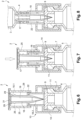
- THE figures 6 to 8 represent a connection device 2 according to a third embodiment of the invention which differs from the first and second embodiments represented on the figures 1 to 5 essentially in that the protective cap 25 is mounted movable relative to the mounting part 10 between a first protective position (see Figure 6 ) in which the protective cap 25 is distant from the mounting part 10 and a second protective position (see Figure 7 ) in which the protective cap 25 is brought closer to the mounting part 10, and in that the protective cap 25 and the perforation element 18 are configured such that a movement of the protective cap 25 from the first protection position to the second protection position automatically causes a movement of the perforation element 18 from the rest position to the perforation position.
- Such a configuration of the protective cap 25 makes it possible to ensure perforation of the perforable closing element 9 without risk of contamination of the female connection end 17.
- connection device 2 advantageously comprises guide means configured to guide the protective cap 25 relative to the mounting part 10 during movement of the protective cap 25 of the first protection position towards the second protection position.
- the guide means are for example configured to guide the protective cap 25 relative to the mounting part 10 in a helical movement or in a longitudinal movement in the direction of the mounting part 10 during movement of the protective cap 25 from the first protection position to the second protection position.
- the guide means are also configured to guide the protective cap 25 relative to the mounting part 10 during a movement of the protective cap 25 from the second protective position towards a position for removing the protective cap. protection 25.
- the guide means are for example configured to guide the protective cap 25 relative to the mounting part 10 in a helical movement opposite to the mounting part 10 during movement of the protective cap 25 from the second protective position towards the withdrawal position, or according to a first rotational movement and according to a second longitudinal movement opposite the mounting part 10 during a movement of the protective cap 25 from the second position of protection towards the removed position.
- the guide means may for example comprise a guide pin provided on the protective cap 25 or the mounting part 10, and a guide groove provided on the mounting part 10 or the protective cap 25, the guide pin being slidably mounted in the guide groove.
- the guide groove may for example comprise a first groove part wound helically, and a second groove part extending in the extension of the first groove part and substantially parallel to the longitudinal axis of the connection device 2.
- connection device 2 comprises a filtration chamber 36 and in that the perforation element 18 further comprises a vent channel 37 which is configured to fluidly connect the filtration chamber 36 with the internal volume 21 of the bottle body when the perforation element 18 is in the perforation position, and in that the connection device 2 comprises at least one air filter 38 which is arranged upstream of the updating channel air 37.
- the or each air filter 38 is permeable to air and impermeable to microorganisms.
- the or each air filter 38 is also impermeable to liquid at atmospheric pressure.
- the or each air filter 38 is more particularly fixed to the perforation element 18 and is configured to filter the air which comes from outside the connection device 2 and which is intended to flow through the channel of vent 37.
- the vent channel 37 opens into the filtration chamber 36, and the or each air filter 38 forms at least partially one of the walls of the filtration chamber 36.
- the protective cap 25 is configured such that removal of the protective cap 25, for example by unscrewing or loosening or unclipping, automatically causes movement of the perforation element 18 from the rest position to the perforation position.
- connection device 2 may for example comprise first guide means configured to guide the perforation element 18 relative to the guide part 22 in a helical movement in the direction of the mounting part 10 during removal of the protective cap 25, and more particularly when unscrewing the protective cap 25.
- the first guide means may for example comprise a guide pin 39 provided on the guide part 22 or on the perforation element 18, and a helical guide groove 41 provided on the perforation element 18 or the guide part 22, the guide pin 39 being slidably mounted in the helical guide groove 41.
- connection device 2 may for example comprise second guide means configured to guide the perforation element 18 relative to the protective cap 25 in a longitudinal movement towards the mounting part 10 during removal of the protective cap. protection 25, and more particularly when unscrewing the protective cap 25.
- the second guide means comprise two guide projections 42 which are provided on the perforation element 18 and which are diametrically opposed, and two longitudinal guide grooves 43 which are provided on the protective cap 25, each guide projection 42 being slidably mounted in a respective longitudinal guide groove 43.
- the perforation element 18 is automatically moved into the perforation position in which the vent channel 37 fluidly connects the internal volume 21 of the bottle body with the chamber of filtration 36.
- the connection channel 19 When taking a quantity of the product contained in the bottle 5 via the connection channel 19, air is sucked in and filtered through the air filter(s) 38 and the filtered air flows through the vent channel 37 to the internal volume 21 of the bottle body.
Landscapes
- Health & Medical Sciences (AREA)
- Pharmacology & Pharmacy (AREA)
- Life Sciences & Earth Sciences (AREA)
- Animal Behavior & Ethology (AREA)
- General Health & Medical Sciences (AREA)
- Public Health (AREA)
- Veterinary Medicine (AREA)
- Physics & Mathematics (AREA)
- Fluid Mechanics (AREA)
- Closures For Containers (AREA)
- Medical Preparation Storing Or Oral Administration Devices (AREA)
- Infusion, Injection, And Reservoir Apparatuses (AREA)
Claims (15)
- Anschlussvorrichtung (2), die ausgelegt ist, um einen Behälter (3), der ein männliches Verbindungsstück (4) aufweist, an eine Flasche (5) anzuschließen, die einen Flaschenkörper (6) aufweist, der mit einem Hals (7) ausgestattet ist, der von einem perforierbaren Verschlusselement (9) dicht verschlossen ist, wobei die Anschlussvorrichtung (2) aufweist:- einen Montageteil (10), der ausgelegt ist, um auf dem Flaschenkörper (6) angebracht zu sein,- ein weibliches Verbindungsstück (17), das zur Verbindung mit dem männlichen Verbindungsstück (4) des Behälters (3) bestimmt ist,- ein Perforationselement (18), das einen Verbindungskanal (19) aufweist und das ausgelegt ist, um das perforierbare Verschlusselement (9) zu perforieren, wobei das Perforationselement (18) zwischen einer Ruhestellung und einer Perforationsstellung, in der, wenn die Anschlussvorrichtung (2) auf dem Flaschenkörper (6) angebracht ist, das Perforationselement (18) imstande ist, das perforierbare Verschlusselement (9) zu perforieren, beweglich ist und der Verbindungskanal (19) imstande ist, das weibliche Verbindungsstück (17) mit einem Innenvolumen (21) des Flaschenkörpers (6) fluidisch zu verbinden,- eine Schutzkappe (25), die lösbar ist und die mindestens zum Teil eine innere Kammer (26) begrenzt, in der sich mindestens zum Teil das weibliche Verbindungsstück (17) erstreckt, wobei die Schutzkappe (25) das weibliche Verbindungsstück (17) mindestens zum Teil bedeckt und mindestens zum Teil schützt,dadurch gekennzeichnet, dass die Anschlussvorrichtung ferner aufweist:- mindestens eine Durchgangsöffnung (29), die in die innere Kammer (26) ausmündet, wobei die mindestens eine Durchgangsöffnung (29) für den Durchgang eines Sterilisationsgases bestimmt ist, und- eine Verschlussmembran (31), die die mindestens eine Durchgangsöffnung (29) mindestens zum Teil bedeckt, wobei Verschlussmembran (31) porös und für das Sterilisationsgas durchlässig ist.
- Anschlussvorrichtung (2) nach Anspruch 1, wobei die Verschlussmembran (31) aus Tyvek oder aus porösem und für ein Sterilisationsgas durchlässigem Papier ist.
- Anschlussvorrichtung (2) nach Anspruch 1 oder 2, wobei die mindestens eine Durchgangsöffnung (29) auf der Schutzkappe (25) vorgesehen ist.
- Anschlussvorrichtung (2) nach einem der Ansprüche 1 bis 3, wobei die Verschlussmembran (31) auf der Schutzkappe (25) befestigt ist.
- Anschlussvorrichtung (2) nach einem der Ansprüche 1 bis 4, die ferner einen Führungsteil (22) aufweist, der ausgelegt ist, um das Perforationselement (18) bei einer Verlagerung des Perforationselements (18) aus der Ruhestellung in die Perforationsstellung zu führen.
- Anschlussvorrichtung (2) nach einem der Ansprüche 1 bis 5, wobei das weibliche Verbindungsstück (17) auf einem proximalen Endabschnitt (18.1) des Perforationselements (18) vorgesehen ist.
- Anschlussvorrichtung (2) nach Anspruch 5, wobei das weibliche Verbindungsstück (17) auf einem proximalen Endabschnitt des Führungsteils (22) vorgesehen ist.
- Anschlussvorrichtung (2) nach einem der Ansprüche 1 bis 7, wobei das weibliche Verbindungsstück (17) und das Perforationselement (18) derart ausgelegt sind, dass eine Verbindung eines männlichen Verbindungselements (4) auf dem weiblichen Verbindungselement (17) eine Verlagerung des Perforationselements (18) aus der Ruhestellung in die Perforationsstellung bewirkt.
- Anschlussvorrichtung (2) nach einem der Ansprüche 1 bis 8, wobei die Schutzkappe (25) im Verhältnis zum Montageteil (10) zwischen einer ersten Schutzstellung, in der die Schutzkappe (25) vom Montageteil (10) entfernt ist, und einer zweiten Schutzstellung, in der die Schutzkappe (25) an den Montageteil (10) angenähert ist, beweglich angebracht ist, wobei die Schutzkappe (25) und das Perforationselement (18) derart ausgelegt sind, dass eine Verlagerung der Schutzkappe (25) aus der ersten Schutzstellung in die zweiten Schutzstellung eine Verlagerung des Perforationselements (18) aus der Ruhestellung in die Perforationsstellung bewirkt.
- Anschlussvorrichtung (2) nach einem der Ansprüche 1 bis 9, wobei der Montageteil (10) einen Verankerungsring (11) aufweist, der Verankerungsfüße (12) umfasst, die winklig um eine Längsachse (A) der Anschlussvorrichtung (2) verteilt sind und die mindestens in einer radialen Richtung elastisch verformbar sind, wobei die Verankerungsfüße (12) imstande sind, mit einer ringförmigen Wulst (13) zusammenzuwirken, die auf dem Flaschenkörper (6) vorgesehen sind, so dass die Anschlussvorrichtung (2) am Flaschenkörper (6) befestigt wird.
- Anschlussvorrichtung (2) nach Anspruch 10, wobei der Montageteil (10) ferner einen Verriegelungsring (14) aufweist, der im Verhältnis zum Verankerungsring (11) zwischen eine Freigabestellung, in der die Verankerungslaschen (12) imstande sind, in einer radialen Richtung und nach außen elastisch verformt zu werden, und einer Verriegelungsstellung, in der sich der Verriegelungsring (14) um die Verankerungslaschen (12) erstreckt und die Verankerungslaschen in einer Verankerungsstellung arretiert, in der die Verankerungslaschen (12) mit der ringförmigen Wulst (13) zusammenwirken, die auf dem Flaschenkörper (6) vorgesehen ist, gleitend angebracht ist.
- Anschlussvorrichtung (2) nach einem der Ansprüche 1 bis 11, die ferner einen Unverletzlichkeitsring (32) aufweist, der mit der Schutzkappe (25) anhand einer Vielzahl zerbrechbarer Elemente (33) verbunden ist.
- Verabreichungssystem, das umfasst:- eine Flasche (5), die einen Flaschenkörper (6) aufweist, der mit einem Hals (7) ausgestattet ist, und ein perforierbares Verschlusselement (9), das den Hals (7) des Flaschenkörpers (6) dicht verschließt, und- eine Anschlussvorrichtung (2) nach einem der vorangehenden Ansprüche, wobei die Anschlussvorrichtung (2) am Flaschenkörper (6) befestigt ist.
- Verabreichungssystem nach Anspruch 13, das ferner einen Behälter (3) aufweist, der ein männliches Verbindungsstück (4) aufweist, das bestimmt ist, mit dem weiblichen Verbindungsstück (17) der Anschlussvorrichtung (2) verbunden zu sein.
- Verabreichungssystem nach Anspruch 14, wobei der Behälter (3) eine vorgefüllte Spritze, eine leere Spritze, eine Flasche oder ein Verabreichungsbeutel ist.
Applications Claiming Priority (2)
| Application Number | Priority Date | Filing Date | Title |
|---|---|---|---|
| FR1857211A FR3084582B1 (fr) | 2018-08-01 | 2018-08-01 | Dispositif de connexion configure pour connecter un recipient a un flacon |
| PCT/FR2019/051839 WO2020025883A1 (fr) | 2018-08-01 | 2019-07-24 | Dispositif de connexion configuré pour connecter un récipient à un flacon |
Publications (3)
| Publication Number | Publication Date |
|---|---|
| EP3829519A1 EP3829519A1 (de) | 2021-06-09 |
| EP3829519B1 true EP3829519B1 (de) | 2023-10-04 |
| EP3829519C0 EP3829519C0 (de) | 2023-10-04 |
Family
ID=63963191
Family Applications (1)
| Application Number | Title | Priority Date | Filing Date |
|---|---|---|---|
| EP19759648.9A Active EP3829519B1 (de) | 2018-08-01 | 2019-07-24 | Anschlussvorrichtung zum anschluss eines behälters an eine flasche |
Country Status (7)
| Country | Link |
|---|---|
| US (1) | US20210315777A1 (de) |
| EP (1) | EP3829519B1 (de) |
| JP (1) | JP2021532858A (de) |
| CN (1) | CN112770710A (de) |
| CA (1) | CA3106293A1 (de) |
| FR (1) | FR3084582B1 (de) |
| WO (1) | WO2020025883A1 (de) |
Families Citing this family (1)
| Publication number | Priority date | Publication date | Assignee | Title |
|---|---|---|---|---|
| CN121754786A (zh) * | 2026-03-03 | 2026-03-31 | 山东百多安医疗器械股份有限公司 | 一种具有过滤、防脱帽和防二次使用的预充式冲管注射器 |
Family Cites Families (17)
| Publication number | Priority date | Publication date | Assignee | Title |
|---|---|---|---|---|
| US3882909A (en) * | 1973-07-05 | 1975-05-13 | Ims Ltd | Trans-a-jet 1 |
| US4834152A (en) * | 1986-02-27 | 1989-05-30 | Intelligent Medicine, Inc. | Storage receptacle sealing and transfer apparatus |
| GB9611562D0 (en) * | 1996-06-03 | 1996-08-07 | Applied Research Systems | Device |
| GB9701413D0 (en) * | 1997-01-24 | 1997-03-12 | Smithkline Beecham Biolog | Novel device |
| IT1291848B1 (it) * | 1997-05-02 | 1999-01-21 | Project S A S Di Menichelli Ma | Otturatore per flaconi con dispositivo per il prelievo di quantitativi dosati del liquido contenuto in detti flaconi |
| US6378714B1 (en) * | 1998-04-20 | 2002-04-30 | Becton Dickinson And Company | Transferset for vials and other medical containers |
| US6022339A (en) * | 1998-09-15 | 2000-02-08 | Baxter International Inc. | Sliding reconstitution device for a diluent container |
| US6343629B1 (en) * | 2000-06-02 | 2002-02-05 | Carmel Pharma Ab | Coupling device for coupling a vial connector to a drug vial |
| US7114635B2 (en) * | 2002-05-10 | 2006-10-03 | Santen Pharmaceutical Co., Ltd. | Contamination preventive cap |
| US9480623B2 (en) * | 2011-10-14 | 2016-11-01 | Novo Nordisk Healthcare Ag | Pre-assembled fluid transfer arrangement |
| EP2782544A1 (de) * | 2011-11-22 | 2014-10-01 | Novo Nordisk Health Care AG | Entfernung eines barriereelements |
| JP6609408B2 (ja) * | 2012-12-10 | 2019-11-20 | ニプロ株式会社 | 連結器具 |
| WO2014106047A1 (en) * | 2012-12-28 | 2014-07-03 | Porex Corporation | Sintered porous polymeric caps and vents for components of medical devices |
| TR201904734T4 (tr) * | 2013-02-07 | 2019-04-22 | Equashield Medical Ltd | Kapalı ilaç aktarım sistemindeki ilerlemeler. |
| CA2931949C (en) * | 2013-12-01 | 2020-01-14 | Becton, Dickinson And Company | Medicament device |
| JP5875617B2 (ja) * | 2014-03-13 | 2016-03-02 | テルモ株式会社 | 医療用具接続具および薬剤投与具 |
| WO2015164385A1 (en) * | 2014-04-21 | 2015-10-29 | Becton Dickinson and Company Limited | System with adapter for closed transfer of fluids |
-
2018
- 2018-08-01 FR FR1857211A patent/FR3084582B1/fr not_active Expired - Fee Related
-
2019
- 2019-07-24 CA CA3106293A patent/CA3106293A1/fr active Pending
- 2019-07-24 CN CN201980063804.7A patent/CN112770710A/zh active Pending
- 2019-07-24 US US17/265,110 patent/US20210315777A1/en not_active Abandoned
- 2019-07-24 WO PCT/FR2019/051839 patent/WO2020025883A1/fr not_active Ceased
- 2019-07-24 JP JP2021504358A patent/JP2021532858A/ja active Pending
- 2019-07-24 EP EP19759648.9A patent/EP3829519B1/de active Active
Also Published As
| Publication number | Publication date |
|---|---|
| CA3106293A1 (fr) | 2020-02-06 |
| JP2021532858A (ja) | 2021-12-02 |
| EP3829519A1 (de) | 2021-06-09 |
| EP3829519C0 (de) | 2023-10-04 |
| CN112770710A (zh) | 2021-05-07 |
| FR3084582B1 (fr) | 2023-10-27 |
| US20210315777A1 (en) | 2021-10-14 |
| WO2020025883A1 (fr) | 2020-02-06 |
| FR3084582A1 (fr) | 2020-02-07 |
Similar Documents
| Publication | Publication Date | Title |
|---|---|---|
| EP0403626B1 (de) | Aufbewahrungs- und umfüllflasche zum aufbewahren von zwei bestandteilen einer heilkräftigen substanz | |
| EP1663102B1 (de) | Vorrichtung zur oralen verabreichung eines medikaments | |
| EP0717611B1 (de) | Spritzenvorrichtung zum mischen von zwei präparaten | |
| EP2717827B1 (de) | Vorrichtung zur Verbindung zwischen einem Empfänger und einem Gehäuse und Verfahren zur Montage und Verwendung einer solchen Vorrichtung | |
| US10426703B2 (en) | Vial adapters | |
| EP1694269B1 (de) | Kappe für die sichere verpackng einer medizinflasche | |
| EP1079789B1 (de) | Ampulle zur aufnahme einer medizinischen flüssigkeit | |
| EP2863968B1 (de) | Einspritzanordnung | |
| US10813837B2 (en) | Pre-filled diluent syringe vial adapter | |
| JP5117850B2 (ja) | 血液採集アセンブリ | |
| EP0792135A1 (de) | Spritzenvorrichtung befestigbar an einem fläschchen | |
| FR2836129A1 (fr) | Dispositif de connexion entre un recipient et un contenant et ensemble pret a l'emploi comprenant un tel dispositif | |
| EP1507565B1 (de) | Vorfüllbare einweg-injektionsvorrichtung | |
| WO1999036029A1 (fr) | Dispositif de confinement etanche, pour la connexion d'un recipient et d'un moyen de delivrance d'une matiere | |
| FR2717086A1 (fr) | Dispositif de seringue pour le mélange de deux composés. | |
| EP3829681A1 (de) | Verabreichungssystem mit einer verabreichungsvorrichtung und schutzvorrichtung mit einer verschlussmembran | |
| EP3829519B1 (de) | Anschlussvorrichtung zum anschluss eines behälters an eine flasche | |
| EP1435893B1 (de) | Sicherheitsverpackung für eine flasche für medizinische anwendungen | |
| EP1005429A1 (de) | Mischflasche zur abgabe einer mischung aus zwei vor der abgabe voneinander getrennten produkten und zur deren injekton mittels einer spritze | |
| EP2779981A1 (de) | Vorrichtung zur schnittstellenbildung zwischen einem flüssigkeitseinspritzinstrument und einer zu punktierenden flasche sowie anwendungsverfahren dafür | |
| FR2746653A3 (fr) | Seringue a usage medical | |
| US20240269394A1 (en) | Device for providing container closure integrity and methods of use thereof | |
| HK1243313B (en) | Connector system comprising at least two outlet ports | |
| FR2715311A1 (fr) | Dispositif de seringue pour le mélange de deux composés. |
Legal Events
| Date | Code | Title | Description |
|---|---|---|---|
| STAA | Information on the status of an ep patent application or granted ep patent |
Free format text: STATUS: UNKNOWN |
|
| STAA | Information on the status of an ep patent application or granted ep patent |
Free format text: STATUS: THE INTERNATIONAL PUBLICATION HAS BEEN MADE |
|
| PUAI | Public reference made under article 153(3) epc to a published international application that has entered the european phase |
Free format text: ORIGINAL CODE: 0009012 |
|
| STAA | Information on the status of an ep patent application or granted ep patent |
Free format text: STATUS: REQUEST FOR EXAMINATION WAS MADE |
|
| 17P | Request for examination filed |
Effective date: 20210202 |
|
| AK | Designated contracting states |
Kind code of ref document: A1 Designated state(s): AL AT BE BG CH CY CZ DE DK EE ES FI FR GB GR HR HU IE IS IT LI LT LU LV MC MK MT NL NO PL PT RO RS SE SI SK SM TR |
|
| DAV | Request for validation of the european patent (deleted) | ||
| DAX | Request for extension of the european patent (deleted) | ||
| GRAP | Despatch of communication of intention to grant a patent |
Free format text: ORIGINAL CODE: EPIDOSNIGR1 |
|
| STAA | Information on the status of an ep patent application or granted ep patent |
Free format text: STATUS: GRANT OF PATENT IS INTENDED |
|
| INTG | Intention to grant announced |
Effective date: 20221201 |
|
| GRAJ | Information related to disapproval of communication of intention to grant by the applicant or resumption of examination proceedings by the epo deleted |
Free format text: ORIGINAL CODE: EPIDOSDIGR1 |
|
| STAA | Information on the status of an ep patent application or granted ep patent |
Free format text: STATUS: REQUEST FOR EXAMINATION WAS MADE |
|
| INTC | Intention to grant announced (deleted) | ||
| GRAP | Despatch of communication of intention to grant a patent |
Free format text: ORIGINAL CODE: EPIDOSNIGR1 |
|
| STAA | Information on the status of an ep patent application or granted ep patent |
Free format text: STATUS: GRANT OF PATENT IS INTENDED |
|
| INTG | Intention to grant announced |
Effective date: 20230504 |
|
| GRAS | Grant fee paid |
Free format text: ORIGINAL CODE: EPIDOSNIGR3 |
|
| GRAA | (expected) grant |
Free format text: ORIGINAL CODE: 0009210 |
|
| STAA | Information on the status of an ep patent application or granted ep patent |
Free format text: STATUS: THE PATENT HAS BEEN GRANTED |
|
| AK | Designated contracting states |
Kind code of ref document: B1 Designated state(s): AL AT BE BG CH CY CZ DE DK EE ES FI FR GB GR HR HU IE IS IT LI LT LU LV MC MK MT NL NO PL PT RO RS SE SI SK SM TR |
|
| REG | Reference to a national code |
Ref country code: GB Ref legal event code: FG4D Free format text: NOT ENGLISH |
|
| REG | Reference to a national code |
Ref country code: CH Ref legal event code: EP |
|
| REG | Reference to a national code |
Ref country code: DE Ref legal event code: R096 Ref document number: 602019038683 Country of ref document: DE |
|
| REG | Reference to a national code |
Ref country code: IE Ref legal event code: FG4D Free format text: LANGUAGE OF EP DOCUMENT: FRENCH |
|
| U01 | Request for unitary effect filed |
Effective date: 20231020 |
|
| U07 | Unitary effect registered |
Designated state(s): AT BE BG DE DK EE FI FR IT LT LU LV MT NL PT SE SI Effective date: 20231027 |
|
| PG25 | Lapsed in a contracting state [announced via postgrant information from national office to epo] |
Ref country code: GR Free format text: LAPSE BECAUSE OF FAILURE TO SUBMIT A TRANSLATION OF THE DESCRIPTION OR TO PAY THE FEE WITHIN THE PRESCRIBED TIME-LIMIT Effective date: 20240105 |
|
| PG25 | Lapsed in a contracting state [announced via postgrant information from national office to epo] |
Ref country code: IS Free format text: LAPSE BECAUSE OF FAILURE TO SUBMIT A TRANSLATION OF THE DESCRIPTION OR TO PAY THE FEE WITHIN THE PRESCRIBED TIME-LIMIT Effective date: 20240204 |
|
| PG25 | Lapsed in a contracting state [announced via postgrant information from national office to epo] |
Ref country code: ES Free format text: LAPSE BECAUSE OF FAILURE TO SUBMIT A TRANSLATION OF THE DESCRIPTION OR TO PAY THE FEE WITHIN THE PRESCRIBED TIME-LIMIT Effective date: 20231004 |
|
| PG25 | Lapsed in a contracting state [announced via postgrant information from national office to epo] |
Ref country code: IS Free format text: LAPSE BECAUSE OF FAILURE TO SUBMIT A TRANSLATION OF THE DESCRIPTION OR TO PAY THE FEE WITHIN THE PRESCRIBED TIME-LIMIT Effective date: 20240204 Ref country code: GR Free format text: LAPSE BECAUSE OF FAILURE TO SUBMIT A TRANSLATION OF THE DESCRIPTION OR TO PAY THE FEE WITHIN THE PRESCRIBED TIME-LIMIT Effective date: 20240105 Ref country code: ES Free format text: LAPSE BECAUSE OF FAILURE TO SUBMIT A TRANSLATION OF THE DESCRIPTION OR TO PAY THE FEE WITHIN THE PRESCRIBED TIME-LIMIT Effective date: 20231004 |
|
| PG25 | Lapsed in a contracting state [announced via postgrant information from national office to epo] |
Ref country code: RS Free format text: LAPSE BECAUSE OF FAILURE TO SUBMIT A TRANSLATION OF THE DESCRIPTION OR TO PAY THE FEE WITHIN THE PRESCRIBED TIME-LIMIT Effective date: 20231004 Ref country code: PL Free format text: LAPSE BECAUSE OF FAILURE TO SUBMIT A TRANSLATION OF THE DESCRIPTION OR TO PAY THE FEE WITHIN THE PRESCRIBED TIME-LIMIT Effective date: 20231004 Ref country code: NO Free format text: LAPSE BECAUSE OF FAILURE TO SUBMIT A TRANSLATION OF THE DESCRIPTION OR TO PAY THE FEE WITHIN THE PRESCRIBED TIME-LIMIT Effective date: 20240104 Ref country code: HR Free format text: LAPSE BECAUSE OF FAILURE TO SUBMIT A TRANSLATION OF THE DESCRIPTION OR TO PAY THE FEE WITHIN THE PRESCRIBED TIME-LIMIT Effective date: 20231004 |
|
| REG | Reference to a national code |
Ref country code: DE Ref legal event code: R097 Ref document number: 602019038683 Country of ref document: DE |
|
| PG25 | Lapsed in a contracting state [announced via postgrant information from national office to epo] |
Ref country code: CZ Free format text: LAPSE BECAUSE OF FAILURE TO SUBMIT A TRANSLATION OF THE DESCRIPTION OR TO PAY THE FEE WITHIN THE PRESCRIBED TIME-LIMIT Effective date: 20231004 |
|
| PG25 | Lapsed in a contracting state [announced via postgrant information from national office to epo] |
Ref country code: SK Free format text: LAPSE BECAUSE OF FAILURE TO SUBMIT A TRANSLATION OF THE DESCRIPTION OR TO PAY THE FEE WITHIN THE PRESCRIBED TIME-LIMIT Effective date: 20231004 |
|
| PG25 | Lapsed in a contracting state [announced via postgrant information from national office to epo] |
Ref country code: SM Free format text: LAPSE BECAUSE OF FAILURE TO SUBMIT A TRANSLATION OF THE DESCRIPTION OR TO PAY THE FEE WITHIN THE PRESCRIBED TIME-LIMIT Effective date: 20231004 Ref country code: SK Free format text: LAPSE BECAUSE OF FAILURE TO SUBMIT A TRANSLATION OF THE DESCRIPTION OR TO PAY THE FEE WITHIN THE PRESCRIBED TIME-LIMIT Effective date: 20231004 Ref country code: RO Free format text: LAPSE BECAUSE OF FAILURE TO SUBMIT A TRANSLATION OF THE DESCRIPTION OR TO PAY THE FEE WITHIN THE PRESCRIBED TIME-LIMIT Effective date: 20231004 Ref country code: CZ Free format text: LAPSE BECAUSE OF FAILURE TO SUBMIT A TRANSLATION OF THE DESCRIPTION OR TO PAY THE FEE WITHIN THE PRESCRIBED TIME-LIMIT Effective date: 20231004 |
|
| PLBE | No opposition filed within time limit |
Free format text: ORIGINAL CODE: 0009261 |
|
| STAA | Information on the status of an ep patent application or granted ep patent |
Free format text: STATUS: NO OPPOSITION FILED WITHIN TIME LIMIT |
|
| 26N | No opposition filed |
Effective date: 20240705 |
|
| PG25 | Lapsed in a contracting state [announced via postgrant information from national office to epo] |
Ref country code: MC Free format text: LAPSE BECAUSE OF FAILURE TO SUBMIT A TRANSLATION OF THE DESCRIPTION OR TO PAY THE FEE WITHIN THE PRESCRIBED TIME-LIMIT Effective date: 20231004 |
|
| REG | Reference to a national code |
Ref country code: CH Ref legal event code: PL |
|
| U90 | Renewal fees not paid: noting of loss of rights |
Free format text: RENEWAL FEE NOT PAID FOR YEAR 06 Effective date: 20250214 |
|
| GBPC | Gb: european patent ceased through non-payment of renewal fee |
Effective date: 20240724 |
|
| PG25 | Lapsed in a contracting state [announced via postgrant information from national office to epo] |
Ref country code: CH Free format text: LAPSE BECAUSE OF NON-PAYMENT OF DUE FEES Effective date: 20240731 |
|
| PG25 | Lapsed in a contracting state [announced via postgrant information from national office to epo] |
Ref country code: GB Free format text: LAPSE BECAUSE OF NON-PAYMENT OF DUE FEES Effective date: 20240724 |
|
| U93 | Unitary patent lapsed |
Free format text: RENEWAL FEE NOT PAID Effective date: 20240731 |
|
| PG25 | Lapsed in a contracting state [announced via postgrant information from national office to epo] |
Ref country code: IE Free format text: LAPSE BECAUSE OF NON-PAYMENT OF DUE FEES Effective date: 20240724 |
|
| PG25 | Lapsed in a contracting state [announced via postgrant information from national office to epo] |
Ref country code: CY Free format text: LAPSE BECAUSE OF FAILURE TO SUBMIT A TRANSLATION OF THE DESCRIPTION OR TO PAY THE FEE WITHIN THE PRESCRIBED TIME-LIMIT; INVALID AB INITIO Effective date: 20190724 |
|
| PG25 | Lapsed in a contracting state [announced via postgrant information from national office to epo] |
Ref country code: HU Free format text: LAPSE BECAUSE OF FAILURE TO SUBMIT A TRANSLATION OF THE DESCRIPTION OR TO PAY THE FEE WITHIN THE PRESCRIBED TIME-LIMIT; INVALID AB INITIO Effective date: 20190724 |