EP3829986B1 - Steige aus karton - Google Patents
Steige aus karton Download PDFInfo
- Publication number
- EP3829986B1 EP3829986B1 EP19724332.2A EP19724332A EP3829986B1 EP 3829986 B1 EP3829986 B1 EP 3829986B1 EP 19724332 A EP19724332 A EP 19724332A EP 3829986 B1 EP3829986 B1 EP 3829986B1
- Authority
- EP
- European Patent Office
- Prior art keywords
- shell
- support web
- crate
- bent
- glued
- Prior art date
- Legal status (The legal status is an assumption and is not a legal conclusion. Google has not performed a legal analysis and makes no representation as to the accuracy of the status listed.)
- Active
Links
Images




Classifications
-
- B—PERFORMING OPERATIONS; TRANSPORTING
- B65—CONVEYING; PACKING; STORING; HANDLING THIN OR FILAMENTARY MATERIAL
- B65D—CONTAINERS FOR STORAGE OR TRANSPORT OF ARTICLES OR MATERIALS, e.g. BAGS, BARRELS, BOTTLES, BOXES, CANS, CARTONS, CRATES, DRUMS, JARS, TANKS, HOPPERS, FORWARDING CONTAINERS; ACCESSORIES, CLOSURES, OR FITTINGS THEREFOR; PACKAGING ELEMENTS; PACKAGES
- B65D5/00—Rigid or semi-rigid containers of polygonal cross-section, e.g. boxes, cartons or trays, formed by folding or erecting one or more blanks made of paper
- B65D5/001—Rigid or semi-rigid containers of polygonal cross-section, e.g. boxes, cartons or trays, formed by folding or erecting one or more blanks made of paper stackable
- B65D5/0015—Rigid or semi-rigid containers of polygonal cross-section, e.g. boxes, cartons or trays, formed by folding or erecting one or more blanks made of paper stackable the container being formed by folding up portions connected to a central panel
- B65D5/003—Rigid or semi-rigid containers of polygonal cross-section, e.g. boxes, cartons or trays, formed by folding or erecting one or more blanks made of paper stackable the container being formed by folding up portions connected to a central panel having ledges formed by extensions of the side walls
- B65D5/0035—Rigid or semi-rigid containers of polygonal cross-section, e.g. boxes, cartons or trays, formed by folding or erecting one or more blanks made of paper stackable the container being formed by folding up portions connected to a central panel having ledges formed by extensions of the side walls the ledges being located between side walls and doubled-over extensions
-
- B—PERFORMING OPERATIONS; TRANSPORTING
- B65—CONVEYING; PACKING; STORING; HANDLING THIN OR FILAMENTARY MATERIAL
- B65D—CONTAINERS FOR STORAGE OR TRANSPORT OF ARTICLES OR MATERIALS, e.g. BAGS, BARRELS, BOTTLES, BOXES, CANS, CARTONS, CRATES, DRUMS, JARS, TANKS, HOPPERS, FORWARDING CONTAINERS; ACCESSORIES, CLOSURES, OR FITTINGS THEREFOR; PACKAGING ELEMENTS; PACKAGES
- B65D5/00—Rigid or semi-rigid containers of polygonal cross-section, e.g. boxes, cartons or trays, formed by folding or erecting one or more blanks made of paper
- B65D5/001—Rigid or semi-rigid containers of polygonal cross-section, e.g. boxes, cartons or trays, formed by folding or erecting one or more blanks made of paper stackable
-
- B—PERFORMING OPERATIONS; TRANSPORTING
- B65—CONVEYING; PACKING; STORING; HANDLING THIN OR FILAMENTARY MATERIAL
- B65D—CONTAINERS FOR STORAGE OR TRANSPORT OF ARTICLES OR MATERIALS, e.g. BAGS, BARRELS, BOTTLES, BOXES, CANS, CARTONS, CRATES, DRUMS, JARS, TANKS, HOPPERS, FORWARDING CONTAINERS; ACCESSORIES, CLOSURES, OR FITTINGS THEREFOR; PACKAGING ELEMENTS; PACKAGES
- B65D5/00—Rigid or semi-rigid containers of polygonal cross-section, e.g. boxes, cartons or trays, formed by folding or erecting one or more blanks made of paper
- B65D5/001—Rigid or semi-rigid containers of polygonal cross-section, e.g. boxes, cartons or trays, formed by folding or erecting one or more blanks made of paper stackable
- B65D5/0015—Rigid or semi-rigid containers of polygonal cross-section, e.g. boxes, cartons or trays, formed by folding or erecting one or more blanks made of paper stackable the container being formed by folding up portions connected to a central panel
-
- B—PERFORMING OPERATIONS; TRANSPORTING
- B65—CONVEYING; PACKING; STORING; HANDLING THIN OR FILAMENTARY MATERIAL
- B65D—CONTAINERS FOR STORAGE OR TRANSPORT OF ARTICLES OR MATERIALS, e.g. BAGS, BARRELS, BOTTLES, BOXES, CANS, CARTONS, CRATES, DRUMS, JARS, TANKS, HOPPERS, FORWARDING CONTAINERS; ACCESSORIES, CLOSURES, OR FITTINGS THEREFOR; PACKAGING ELEMENTS; PACKAGES
- B65D5/00—Rigid or semi-rigid containers of polygonal cross-section, e.g. boxes, cartons or trays, formed by folding or erecting one or more blanks made of paper
- B65D5/001—Rigid or semi-rigid containers of polygonal cross-section, e.g. boxes, cartons or trays, formed by folding or erecting one or more blanks made of paper stackable
- B65D5/0015—Rigid or semi-rigid containers of polygonal cross-section, e.g. boxes, cartons or trays, formed by folding or erecting one or more blanks made of paper stackable the container being formed by folding up portions connected to a central panel
- B65D5/003—Rigid or semi-rigid containers of polygonal cross-section, e.g. boxes, cartons or trays, formed by folding or erecting one or more blanks made of paper stackable the container being formed by folding up portions connected to a central panel having ledges formed by extensions of the side walls
Definitions
- the invention relates to a crate made of cardboard with a jacket which, in the area of the corners of the jacket, forms stacking lugs that protrude in height over the jacket and between the stacking lugs, reinforced, upper longitudinal edge sections in the form of inwardly folded edge flaps, which form a support web parallel to the floor by two Crease lines are bent back against the jacket and glued to the jacket with the bent-back tab section.
- the casing walls between the casing corners with the stacking approaches are reinforced by inwardly folded edge flaps, which are bent back by two score lines to form a base-parallel support web against the casing wall and are glued to the casing wall with the bent-back flap section.
- the invention is therefore based on the object of designing a crate of the type mentioned at the outset in such a way that the supporting webs of the finished crate run parallel to the floor even when the cardboard blank is erected by machine.
- the invention solves the problem with a crate of the type described above in that the score line between the shell and the supporting web has a lower height than the score line between the receiving web and the bent-back tab section glued to the shell.
- the tab section to be glued to the jacket is first folded around the higher score line between the support web and the tab section and only then the support web around the lower score line between the jacket wall and the support web, whereby due to the higher score line the elastic recovery of the tab section relative to the support bar is less than the elastic recovery of the support bar relative to the casing wall.
- This causes the support bar to rise slightly towards the inside of the crate after it has been erected and can therefore be pressed into the exact position by the mechanical erector before the tab section is glued to the casing.
- the tab section of the edge tabs that is to be glued to the sleeve is bent back by at least one crease line against the support web and then glued to the sleeve, the result is a reinforcement of the triangular composite of the sleeve, the support web, the edge tab bent back against the sleeve and in the same way again tab section bent back against the support web.
- an unfavorable elastic recovery for the mechanical erection of the blank of the flap section bent back against the support web can occur in relation to the edge flap bent back around the support web.
- the tab sections can have punched-out portions distributed along the length of the score line, which limit the restoring moment.
- the tray made of cardboard erected from such a blank comprises a base 1 that is rectangular in its basic shape and a jacket 2 that rises up from the base 1 and consists of pairs of opposing jacket walls 3, 4, which are surrounded by score lines 5, 6 be erected relative to the floor 1.
- the casing walls 3 are provided with connecting straps 7 which are glued to the casing walls 4 adjoining them.
- the jacket walls 3 have tabs 8 which are bent inwards by 90° around score lines 9 and form attached adhesive tabs 10 .
- the casing walls 4 overlap the inwardly bent connecting flaps 7 of the casing walls 3. Since the casing walls 4 have recesses 11 on one side of the crate in the area of the adhesive flaps 10, the adhesive flaps 10 can be glued to the outside of the connecting flaps 7 without over the shell walls 4 protrude.
- the casing walls 4 are correspondingly lower, so that the connecting flaps 7 protrude beyond the casing walls 4 in the area of the adhesive flaps 10 . In both cases, the connecting lugs 7 are effective as part of the jacket walls 4.
- protruding latching lugs 12 are formed, which positively engage in corresponding recesses 13 in the base 1 and in the shell walls 3, 4 of identical risers.
- the jacket walls 3 are provided with edge tabs 14 which are bent back towards the jacket wall 4 by two score lines 15, 16 to form a support web 17 parallel to the floor and are glued to the jacket wall 3 with a tab section 18.
- This tab portion 18 extends according to the embodiment of Figures 1 to 3 in the direction of the bottom 1, but can also according to the 4 and 5 be folded back by 180° against the support bar 17.
- the support webs 17 In order that loads from trays stacked on top of one another can be advantageously transferred to the casing walls 3 via the support webs 17 , the support webs 17 must be aligned parallel to the floor, so that the base 1 of a tray that is placed on it rests flat against the support webs 17 . In order to be able to ensure such a ground-parallel alignment of the support webs 17 when the crate is erected by machine from the flat blank, the two creasing lines 15 and 16 delimiting the support webs 17 have unequal heights. Since the score line 16 between the supporting web 17 and the adjoining edge flap 14 is provided with a greater height, i.e.
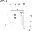
- the edge flap 14 is first folded around the score line 16 and only then around the score line 15 associated with the jacket wall 4 . Due to the fact that the score lines 15 and 16 have different heights, this means that the support bar 17 rises towards the inside of the tray after the edge flap 14 has been bent twice around the score lines 15, 16, as is shown in FIG 3 is indicated by dotted lines. From this initial position, the position of the support web 17 parallel to the floor can then be precisely specified by the erection tool by pressing the support web 17 against the floor 1 .
- the tab section 18 is bent back by two score lines 19 opposite the edge tab 14 against the support web 17 and is glued to the casing wall 3 .
- this bending back by almost 180° causes elastic restoring moments that can impede the erecting process.
- punched-out portions 20 are distributed along the length of the creasing lines 19 and extend at least over the distance between the two creasing lines 19, as is the case 4 can be removed.
Landscapes
- Engineering & Computer Science (AREA)
- Mechanical Engineering (AREA)
- Cartons (AREA)
- Auxiliary Devices For And Details Of Packaging Control (AREA)
- Toys (AREA)
Description
- Die Erfindung bezieht sich auf eine Steige aus Karton mit einem Mantel, der im Bereich der Mantelecken der Höhe nach über den Mantel vorstehende Stapelansätze und zwischen den Stapelansätzen verstärkte, obere Längsrandabschnitte in Form von einwärts gefalzten Randlaschen bildet, die unter Ausbildung eines bodenparallelen Auflagestegs um zwei Rilllinien gegen den Mantel zurückgebogen und mit dem zurückgebogenen Laschenabschnitt am Mantel festgeklebt sind.
- Um für Steigen aus Karton eine hohe Formstabilität und eine an die rauen Betriebsanforderungen angepasste Stapelbarkeit sicherzustellen, ist es bekannt (
AT 516270 A1 - Der Erfindung liegt somit die Aufgabe zugrunde, eine Steige der eingangs genannten Art so auszubilden, dass auch bei einer maschinellen Aufrichtung des Zuschnitts aus Karton die Auflagestege der fertigen Steige parallel zum Boden verlaufen.
- Die Erfindung löst die gestellte Aufgabe bei einer Steige der eingangs geschilderten Art dadurch, dass die Rilllinie zwischen dem Mantel und dem Auflagesteg eine geringere Höhe als die Rilllinie zwischen dem Aufnahmesteg und dem zurückgebogenen, am Mantel festgeklebten Laschenabschnitt aufweist.
- Zufolge dieser Maßnahme wird beim maschinellen Aufrichten der Steige aus dem ebenen Zuschnitt zunächst der am Mantel festzuklebende Laschenabschnitt um die höhere Rilllinie zwischen dem Auflagesteg und dem Laschenabschnitt gefaltet und dann erst der Auflagesteg um die niedrigere Rilllinie zwischen Mantelwand und Auflagesteg, wobei aufgrund der höheren Rilllinie die elastische Rückstellung des Laschenabschnitts gegenüber dem Auflagesteg geringer als die elastische Rückstellung des Auflagestegs gegenüber der Mantelwand ausfällt. Dies bewirkt, dass der Auflagesteg nach dem Aufrichten gegen das Innere der Steige geringfügig ansteigt und daher durch den maschinellen Aufrichter in die genaue Lage gedrückt werden kann, bevor der Laschenabschnitt am Mantel festgeklebt wird.
- Wird der am Mantel festzuklebende Laschenabschnitt der Randlaschen um wenigstens eine Rilllinie wieder gegen den Auflagesteg zurückgebogen und dann mit dem Mantel verklebt, so ergibt sich eine Verstärkung des Dreieckverbunds aus dem Mantel, dem Auflagesteg, der gegen den Mantel zurückgebogenen Randlasche und dem im gleichen Sinn nochmals gegen den Auflagesteg zurückgebogenen Laschenabschnitt. In Abhängigkeit von den Eigenschaften des Kartons kann sich eine für das maschinelle Aufrichten des Zuschnitts ungünstige elastische Rückstellung des gegen den Auflagesteg zurückgebogenen Laschenabschnitts gegenüber der um den Auflagesteg zurückgebogenen Randlasche einstellen. Um diese elastische Rückstellung nach dem Falten zu begrenzen, kann der Laschenabschnitte entlang der Rilllinie über deren Länge verteilte Ausstanzungen aufweisen, die das Rückstellmoment begrenzen. Werden die am Mantel festzuklebenden Laschenabschnitte um zwei Rilllinien gegen den Auflagesteg zurückgebogen, was bei dickeren Kartons erforderlich ist, so empfiehlt es sich, die Ausstanzungen zumindest über den Abstand zwischen den beiden Rilllinien zu erstrecken, um eine entsprechende Verringerung des Rückstellmoments sicherzustellen.
- In der Zeichnung ist der Erfindungsgegenstand beispielsweise dargestellt. Es zeigen
- Fig. 1
- einen Kartonzuschnitt für eine erfindungsgemäße Steige ausschnittweise im Bereich einer Mantelwand.
- Fig. 2
- eine Draufsicht auf einen Eckbereich einer aus dem Zuschnitt nach
Fig. 1 aufgerichteten Steige in einem größeren Maßstab, - Fig. 3
- einen Schnitt nach der Linie III-III der
Fig. 2 , - Fig. 4
- eine der
Fig. 1 entsprechende Darstellung einer Abwandlung eines erfindungsgemäßen Kartonzuschnitts und - Fig. 5
- eine aus einem Zuschnitt nach der
Fig. 4 aufgerichteten Steige im Schnitt entlang der Linie V-V derFig. 4 in einem größeren Maßstab. - Wie sich insbesondere aus den in den
Fig. 1 und2 dargestellten Zuschnitten ergibt, umfasst die aus einem solchen Zuschnitt aufgerichtete Steige aus Karton, üblicherweise aus einem Wellkarton, einen in seiner Grundform rechteckigen Boden 1 und einen vom Boden 1 aufragenden Mantel 2 aus einander paarweise gegenüberliegenden Mantelwänden 3, 4, die um Rilllinien 5, 6 gegenüber dem Boden 1 aufgerichtet werden. Zur Verbindung der Mantelwände 3, 4 im Bereich der Mantelecken sind die Mantelwände 3 mit Verbindungslaschen 7 versehen, die mit den anschießenden Mantelwänden 4 verklebt werden. - Im Bereich der Mantelecken weisen die Mantelwände 3 Ansatzlappen 8 auf, die um Rilllinien 9 um 90° einwärtsgebogen werden und angesetzte Klebelaschen 10 bilden. Beim Aufrichten der Steige übergreifen die Mantelwände 4 die einwärts gebogenen Verbindungslaschen 7 der Mantelwände 3. Da die Mantelwände 4 auf einer Seite der Steige im Bereich der Klebelaschen 10 Aussparungen 11 aufweisen, können die Klebelaschen 10 an der Außenseite der Verbindungslaschen 7 festgeklebt werden, ohne über die Mantelwände 4 vorzustehen. Auf der gegenüberliegenden Steigenseite sind die Mantelwände 4 entsprechend niedriger, sodass die Verbindungslaschen 7 die Mantelwände 4 im Bereich der Klebelaschen 10 überragen. In beiden Fällen werden die Verbindungslaschen 7 als Teil der Mantelwände 4 wirksam.
- Mithilfe der Ansatzlappen 8, die auch in anderer Weise mit den Mantelwänden 4 verklebt werden können, werden somit vorstehende Rastansätze 12 gebildet, die in entsprechende Aussparungen 13 im Boden 1 und in den Mantelwänden 3, 4 aufgesetzter, baugleicher Steigen formschlüssig eingreifen.
- Zwischen den Mantelecken sind die Mantelwände 3 mit Randlaschen 14 versehen, die um zwei Rilllinien 15, 16 unter Ausbildung eines bodenparallelen Auflagestegs 17 gegen die Mantelwand 4 zurückgebogen und mit einem Laschenabschnitt 18 an der Mantelwand 3 festgeklebt sind. Dieser Laschenabschnitt 18 erstreckt sich nach dem Ausführungsbeispiel der
Fig. 1 bis 3 in Richtung des Bodens 1, kann aber auch gemäß denFig. 4 und5 um 180° gegen den Auflagesteg 17 hin zurückgefalzt werden. - Damit über die Auflagestege 17 Auflasten von übereinander gestapelten Steigen auf die Mantelwände 3 vorteilhaft abgetragen werden können, ist eine bodenparallele Ausrichtung der Auflagestege 17 erforderlich, sodass der Boden 1 einer aufgesetzten Steige flächig an den Auflagestegen 17 anliegt. Um eine solche bodenparallele Ausrichtung der Auflagestege 17 bei einer maschinellen Aufrichtung der Steige aus dem ebenen Zuschnitt sicherstellen zu können, weisen die beiden die Auflagestege 17 begrenzenden Rilllinien 15 und 16 ungleiche Höhen auf. Da die Rilllinie 16 zwischen dem Auflagesteg 17 und der anschließenden Randlasche 14 mit einer größeren Höhe versehen ist, also eine größere Tiefe als die Rilllinie 15 zwischen der Mantelwand 3 und dem Auflagesteg 17 besitzt, wird erreicht, dass beim maschinellen Aufrichten der Steige stets die Randlasche 14 zuerst um die Rilllinie 16 und dann erst um die der Mantelwand 4 zugeordnete Rilllinie 15 gefaltet wird. Dies bedingt aufgrund der zufolge der unterschiedlich hohen Rilllinien 15 und 16 unterschiedlichen elastischen Rückstellmomente, dass der Auflagesteg 17 nach dem zweimaligen Umbiegen der Randlasche 14 um die Rilllinien 15, 16 gegen das Innere der Steige hin ansteigt, wie dies in der
Fig. 3 strichpunktiert angedeutet ist. Aus dieser Ausgangslage kann dann durch ein Niederdrücken des Auflagestegs 17 gegen den Boden 1 die bodenparallele Lage des Auflagestegs 17 durch das Aufrichtwerkzeug genau vorgegeben werden. - Zum Unterschied zu dem Ausführungsbeispiel nach den
Fig. 1 bis 3 wird gemäß denFig. 4 und5 der Laschenabschnitt 18 um zwei Rilllinien 19 gegenüber der Randlasche 14 gegen den Auflagesteg 17 zurückgebogen und mit der Mantelwand 3 verklebt. Dieses Zurückbiegen um fast 180° bewirkt beim maschinellen Aufrichten der Steige elastische Rückstellmomente, die den Aufrichtvorgang behindern können. Aus diesem Grund werden entlang der Rilllinien 19 über deren Länge verteilt Ausstanzungen 20 vorgesehen, die sich zumindest über den Abstand zwischen den beiden Rilllinien 19 erstrecken, wie dies derFig. 4 entnommen werden kann. Durch diese Ausstanzungen 20 kann auf die elastischen Rückstellmomente beim zweifachen Biegen des Laschenabschnitts 18 um die Rilllinien 19 Einfluss genommen werden, und zwar insbesondere dann, wenn die Breite dieser Ausstanzungen 19 entweder durch die Rilllinien 19 begrenzt wird oder die Ausstanzungen 20 über diese Rilllinien vorstehen.
Claims (3)
- Steige aus Karton mit einem Mantel (2), der im Bereich der Mantelecken der Höhe nach über den Mantel (2) vorstehende Stapelansätze (12) und zwischen den Stapelansätzen (12) verstärkte, obere Längsrandabschnitte in Form von einwärts gefalzten Randlaschen (14) bildet, die unter Ausbildung eines bodenparallelen Auflagestegs (17) um zwei Rilllinien (15, 16) gegen den Mantel (2) zurückgebogen und mit einem zurückgebogenen Laschenabschnitt (18) am Mantel (2) festgeklebt sind, dadurch gekennzeichnet, dass die Rilllinie (15) zwischen dem Mantel (2) und dem Auflagesteg (17) eine geringere Höhe als die Rilllinie (16) zwischen dem Auflagesteg (17) und dem zurückgebogenen, am Mantel (2) festgeklebten Laschenabschnitt (18) aufweist, die Rilllinie (16) also eine größere Tiefe als die Rilllinie (15) zwischen der Mantelwand (3) und dem Auflagesteg (17) besitzt, wobei aufgrund der höheren Rilllinie (16) die elastische Rückstellung des Laschenabschnitts (18) gegenüber dem Auflagesteg (17) geringer als die elastische Rückstellung des Auflagestegs (17) gegenüber der Mantelwand (3) ausfällt.
- Steige nach Anspruch 1, dadurch gekennzeichnet, dass die am Mantel (2) festgeklebten Laschenabschnitte (18) um wenigstens eine Rilllinie (19) gegen den Auflagestege (17) zurückgebogen sind und entlang der Rilllinie (19) über deren Länge verteilte Ausstanzungen (20) aufweist.
- Steige nach Anspruch 2, dadurch gekennzeichnet, dass die Laschenabschnitte (18) um zwei Rilllinien (19) gegen den Auflagesteg (17) zurückgebogen sind und dass sich die Ausstanzungen (20) zumindest über den Abstand zwischen den beiden Rilllinien (19) erstrecken.
Priority Applications (1)
| Application Number | Priority Date | Filing Date | Title |
|---|---|---|---|
| HRP20230891TT HRP20230891T1 (hr) | 2018-07-30 | 2019-04-26 | Kartonski sanduk |
Applications Claiming Priority (2)
| Application Number | Priority Date | Filing Date | Title |
|---|---|---|---|
| ATA50664/2018A AT520815B1 (de) | 2018-07-30 | 2018-07-30 | Steige aus Karton |
| PCT/AT2019/050014 WO2020023984A1 (de) | 2018-07-30 | 2019-04-26 | Steige aus karton |
Publications (3)
| Publication Number | Publication Date |
|---|---|
| EP3829986A1 EP3829986A1 (de) | 2021-06-09 |
| EP3829986C0 EP3829986C0 (de) | 2023-07-19 |
| EP3829986B1 true EP3829986B1 (de) | 2023-07-19 |
Family
ID=66554073
Family Applications (1)
| Application Number | Title | Priority Date | Filing Date |
|---|---|---|---|
| EP19724332.2A Active EP3829986B1 (de) | 2018-07-30 | 2019-04-26 | Steige aus karton |
Country Status (5)
| Country | Link |
|---|---|
| EP (1) | EP3829986B1 (de) |
| AT (1) | AT520815B1 (de) |
| HR (1) | HRP20230891T1 (de) |
| PL (1) | PL3829986T3 (de) |
| WO (1) | WO2020023984A1 (de) |
Family Cites Families (4)
| Publication number | Priority date | Publication date | Assignee | Title |
|---|---|---|---|---|
| FR1358881A (fr) * | 1963-06-07 | 1964-04-17 | Saves S P A | Caisse démontable en papier, carton ou similaire pour le transport et le stockage de produits potagers ou fruitiers en vrac |
| AT516270B1 (de) | 2014-09-16 | 2016-04-15 | Maier Gottfried | Steige |
| AT516466B1 (de) * | 2014-10-30 | 2016-08-15 | Maier Gottfried | Steige in Form einer laschenverklebten Schachtel aus Karton |
| AT518898B1 (de) * | 2016-10-07 | 2018-02-15 | Gottfried Maier | Steige in Form einer laschenverklebten Schachtel aus Karton |
-
2018
- 2018-07-30 AT ATA50664/2018A patent/AT520815B1/de not_active IP Right Cessation
-
2019
- 2019-04-26 PL PL19724332.2T patent/PL3829986T3/pl unknown
- 2019-04-26 EP EP19724332.2A patent/EP3829986B1/de active Active
- 2019-04-26 HR HRP20230891TT patent/HRP20230891T1/hr unknown
- 2019-04-26 WO PCT/AT2019/050014 patent/WO2020023984A1/de not_active Ceased
Also Published As
| Publication number | Publication date |
|---|---|
| EP3829986C0 (de) | 2023-07-19 |
| WO2020023984A1 (de) | 2020-02-06 |
| HRP20230891T1 (hr) | 2023-11-24 |
| PL3829986T3 (pl) | 2023-11-06 |
| AT520815B1 (de) | 2019-08-15 |
| AT520815A4 (de) | 2019-08-15 |
| EP3829986A1 (de) | 2021-06-09 |
Similar Documents
| Publication | Publication Date | Title |
|---|---|---|
| EP3194281B1 (de) | Steige in form einer laschenverklebten schachtel aus karton | |
| AT516466B1 (de) | Steige in Form einer laschenverklebten Schachtel aus Karton | |
| DE4003104A1 (de) | Verpackungsbehaelter, insbesondere zur aufnahme von schokoladenartikeln, und zuschnitt zur bildung desselben | |
| EP3829986B1 (de) | Steige aus karton | |
| DE102014211820A1 (de) | Stapelbarer Faltkarton | |
| EP3512776B1 (de) | Stapelbare steige aus karton | |
| EP3819225B1 (de) | Steige aus karton | |
| EP3523209B1 (de) | Steige in form einer laschenverklebten schachtel aus karton | |
| EP3642122B1 (de) | Steige aus karton | |
| DE102014017999B3 (de) | Karton mit Automatikboden | |
| AT515908B1 (de) | Steige in Form einer laschenverklebten Schachtel aus Karton | |
| CH591369A5 (en) | Corner reinforced folded cardboard box - has end walls doubled over and inclined inwards to form stacking supports at corners (OE 15.6.77) | |
| DE202016002434U1 (de) | Verpackung | |
| DE202022104095U1 (de) | Deckel und Faltkarton | |
| DE202024102489U1 (de) | Kartonzuschnitt zur Herstellung einer Gebindeverstärkung und Gebindeverstärkung | |
| EP1498356A2 (de) | Quaderförmige Faltschachtel und Zuschnitt hierfür | |
| DE102015222742A1 (de) | Verpackung | |
| DE19748799A1 (de) | Verpackungselement, insbesondere aus Pappe | |
| DE8233873U1 (de) | Zuschnitt fuer einen Faltkarton | |
| DE3630391A1 (de) | Aufrichtbare faltschachtel | |
| DE20112752U1 (de) | Verpackungseinheit mit achteckigem Querschnitt | |
| DE8213694U1 (de) | Steige | |
| DE3541036A1 (de) | Aufrichtbare faltschachtel | |
| DE8427622U1 (de) | Faltbarer Zuschnitt aus Wellpappe Pappe oder aehnlichem Faltbarem Material mit Mitteln zur selbstarretierenden Lagerung von Abschnitten des Zuschnitts beim Aufrichte desselben zu einem raeumlichen Faltkoerper in Form eines Behaeltnisses Trays Moebelteils Display-Staender od dgl | |
| DE10000983A1 (de) | Faltschachtel und Zuschnitt für diese Faltschachtel |
Legal Events
| Date | Code | Title | Description |
|---|---|---|---|
| REG | Reference to a national code |
Ref country code: HR Ref legal event code: TUEP Ref document number: P20230891T Country of ref document: HR |
|
| STAA | Information on the status of an ep patent application or granted ep patent |
Free format text: STATUS: UNKNOWN |
|
| STAA | Information on the status of an ep patent application or granted ep patent |
Free format text: STATUS: THE INTERNATIONAL PUBLICATION HAS BEEN MADE |
|
| PUAI | Public reference made under article 153(3) epc to a published international application that has entered the european phase |
Free format text: ORIGINAL CODE: 0009012 |
|
| STAA | Information on the status of an ep patent application or granted ep patent |
Free format text: STATUS: REQUEST FOR EXAMINATION WAS MADE |
|
| 17P | Request for examination filed |
Effective date: 20200228 |
|
| AK | Designated contracting states |
Kind code of ref document: A1 Designated state(s): AL AT BE BG CH CY CZ DE DK EE ES FI FR GB GR HR HU IE IS IT LI LT LU LV MC MK MT NL NO PL PT RO RS SE SI SK SM TR |
|
| DAV | Request for validation of the european patent (deleted) | ||
| DAX | Request for extension of the european patent (deleted) | ||
| GRAP | Despatch of communication of intention to grant a patent |
Free format text: ORIGINAL CODE: EPIDOSNIGR1 |
|
| STAA | Information on the status of an ep patent application or granted ep patent |
Free format text: STATUS: GRANT OF PATENT IS INTENDED |
|
| INTG | Intention to grant announced |
Effective date: 20230208 |
|
| GRAS | Grant fee paid |
Free format text: ORIGINAL CODE: EPIDOSNIGR3 |
|
| GRAA | (expected) grant |
Free format text: ORIGINAL CODE: 0009210 |
|
| STAA | Information on the status of an ep patent application or granted ep patent |
Free format text: STATUS: THE PATENT HAS BEEN GRANTED |
|
| AK | Designated contracting states |
Kind code of ref document: B1 Designated state(s): AL AT BE BG CH CY CZ DE DK EE ES FI FR GB GR HR HU IE IS IT LI LT LU LV MC MK MT NL NO PL PT RO RS SE SI SK SM TR |
|
| REG | Reference to a national code |
Ref country code: GB Ref legal event code: FG4D Free format text: NOT ENGLISH |
|
| REG | Reference to a national code |
Ref country code: CH Ref legal event code: EP |
|
| REG | Reference to a national code |
Ref country code: DE Ref legal event code: R096 Ref document number: 502019008587 Country of ref document: DE |
|
| REG | Reference to a national code |
Ref country code: IE Ref legal event code: FG4D Free format text: LANGUAGE OF EP DOCUMENT: GERMAN |
|
| U01 | Request for unitary effect filed |
Effective date: 20230803 |
|
| U07 | Unitary effect registered |
Designated state(s): AT BE BG DE DK EE FI FR IT LT LU LV MT NL PT SE SI Effective date: 20230808 |
|
| REG | Reference to a national code |
Ref country code: LT Ref legal event code: MG9D |
|
| REG | Reference to a national code |
Ref country code: HR Ref legal event code: T1PR Ref document number: P20230891 Country of ref document: HR |
|
| REG | Reference to a national code |
Ref country code: SK Ref legal event code: T3 Ref document number: E 42532 Country of ref document: SK |
|
| PG25 | Lapsed in a contracting state [announced via postgrant information from national office to epo] |
Ref country code: GR Free format text: LAPSE BECAUSE OF FAILURE TO SUBMIT A TRANSLATION OF THE DESCRIPTION OR TO PAY THE FEE WITHIN THE PRESCRIBED TIME-LIMIT Effective date: 20231020 |
|
| PG25 | Lapsed in a contracting state [announced via postgrant information from national office to epo] |
Ref country code: IS Free format text: LAPSE BECAUSE OF FAILURE TO SUBMIT A TRANSLATION OF THE DESCRIPTION OR TO PAY THE FEE WITHIN THE PRESCRIBED TIME-LIMIT Effective date: 20231119 |
|
| PG25 | Lapsed in a contracting state [announced via postgrant information from national office to epo] |
Ref country code: RS Free format text: LAPSE BECAUSE OF FAILURE TO SUBMIT A TRANSLATION OF THE DESCRIPTION OR TO PAY THE FEE WITHIN THE PRESCRIBED TIME-LIMIT Effective date: 20230719 Ref country code: NO Free format text: LAPSE BECAUSE OF FAILURE TO SUBMIT A TRANSLATION OF THE DESCRIPTION OR TO PAY THE FEE WITHIN THE PRESCRIBED TIME-LIMIT Effective date: 20231019 Ref country code: IS Free format text: LAPSE BECAUSE OF FAILURE TO SUBMIT A TRANSLATION OF THE DESCRIPTION OR TO PAY THE FEE WITHIN THE PRESCRIBED TIME-LIMIT Effective date: 20231119 Ref country code: GR Free format text: LAPSE BECAUSE OF FAILURE TO SUBMIT A TRANSLATION OF THE DESCRIPTION OR TO PAY THE FEE WITHIN THE PRESCRIBED TIME-LIMIT Effective date: 20231020 |
|
| REG | Reference to a national code |
Ref country code: DE Ref legal event code: R097 Ref document number: 502019008587 Country of ref document: DE |
|
| PG25 | Lapsed in a contracting state [announced via postgrant information from national office to epo] |
Ref country code: ES Free format text: LAPSE BECAUSE OF FAILURE TO SUBMIT A TRANSLATION OF THE DESCRIPTION OR TO PAY THE FEE WITHIN THE PRESCRIBED TIME-LIMIT Effective date: 20230719 |
|
| PG25 | Lapsed in a contracting state [announced via postgrant information from national office to epo] |
Ref country code: SM Free format text: LAPSE BECAUSE OF FAILURE TO SUBMIT A TRANSLATION OF THE DESCRIPTION OR TO PAY THE FEE WITHIN THE PRESCRIBED TIME-LIMIT Effective date: 20230719 Ref country code: RO Free format text: LAPSE BECAUSE OF FAILURE TO SUBMIT A TRANSLATION OF THE DESCRIPTION OR TO PAY THE FEE WITHIN THE PRESCRIBED TIME-LIMIT Effective date: 20230719 Ref country code: ES Free format text: LAPSE BECAUSE OF FAILURE TO SUBMIT A TRANSLATION OF THE DESCRIPTION OR TO PAY THE FEE WITHIN THE PRESCRIBED TIME-LIMIT Effective date: 20230719 |
|
| U20 | Renewal fee for the european patent with unitary effect paid |
Year of fee payment: 6 Effective date: 20240325 |
|
| REG | Reference to a national code |
Ref country code: HR Ref legal event code: ODRP Ref document number: P20230891 Country of ref document: HR Payment date: 20240408 Year of fee payment: 6 |
|
| PLBE | No opposition filed within time limit |
Free format text: ORIGINAL CODE: 0009261 |
|
| STAA | Information on the status of an ep patent application or granted ep patent |
Free format text: STATUS: NO OPPOSITION FILED WITHIN TIME LIMIT |
|
| 26N | No opposition filed |
Effective date: 20240422 |
|
| PG25 | Lapsed in a contracting state [announced via postgrant information from national office to epo] |
Ref country code: MC Free format text: LAPSE BECAUSE OF FAILURE TO SUBMIT A TRANSLATION OF THE DESCRIPTION OR TO PAY THE FEE WITHIN THE PRESCRIBED TIME-LIMIT Effective date: 20230719 |
|
| PG25 | Lapsed in a contracting state [announced via postgrant information from national office to epo] |
Ref country code: MC Free format text: LAPSE BECAUSE OF FAILURE TO SUBMIT A TRANSLATION OF THE DESCRIPTION OR TO PAY THE FEE WITHIN THE PRESCRIBED TIME-LIMIT Effective date: 20230719 |
|
| REG | Reference to a national code |
Ref country code: CH Ref legal event code: PL |
|
| PG25 | Lapsed in a contracting state [announced via postgrant information from national office to epo] |
Ref country code: CH Free format text: LAPSE BECAUSE OF NON-PAYMENT OF DUE FEES Effective date: 20240430 |
|
| PG25 | Lapsed in a contracting state [announced via postgrant information from national office to epo] |
Ref country code: IE Free format text: LAPSE BECAUSE OF NON-PAYMENT OF DUE FEES Effective date: 20240426 |
|
| REG | Reference to a national code |
Ref country code: HR Ref legal event code: ODRP Ref document number: P20230891 Country of ref document: HR Payment date: 20250407 Year of fee payment: 7 |
|
| U20 | Renewal fee for the european patent with unitary effect paid |
Year of fee payment: 7 Effective date: 20250425 |
|
| PGFP | Annual fee paid to national office [announced via postgrant information from national office to epo] |
Ref country code: PL Payment date: 20250404 Year of fee payment: 7 |
|
| PGFP | Annual fee paid to national office [announced via postgrant information from national office to epo] |
Ref country code: HR Payment date: 20250407 Year of fee payment: 7 |
|
| PGFP | Annual fee paid to national office [announced via postgrant information from national office to epo] |
Ref country code: SK Payment date: 20250408 Year of fee payment: 7 |
|
| PGFP | Annual fee paid to national office [announced via postgrant information from national office to epo] |
Ref country code: CZ Payment date: 20250414 Year of fee payment: 7 |
|
| PG25 | Lapsed in a contracting state [announced via postgrant information from national office to epo] |
Ref country code: CY Free format text: LAPSE BECAUSE OF FAILURE TO SUBMIT A TRANSLATION OF THE DESCRIPTION OR TO PAY THE FEE WITHIN THE PRESCRIBED TIME-LIMIT; INVALID AB INITIO Effective date: 20190426 |
|
| PGFP | Annual fee paid to national office [announced via postgrant information from national office to epo] |
Ref country code: GB Payment date: 20260319 Year of fee payment: 8 |