EP3830665B1 - Gasdruckregler, ventilanordnung und verfahren zur montage eines gasdruckreglers - Google Patents
Gasdruckregler, ventilanordnung und verfahren zur montage eines gasdruckreglers Download PDFInfo
- Publication number
- EP3830665B1 EP3830665B1 EP19756003.0A EP19756003A EP3830665B1 EP 3830665 B1 EP3830665 B1 EP 3830665B1 EP 19756003 A EP19756003 A EP 19756003A EP 3830665 B1 EP3830665 B1 EP 3830665B1
- Authority
- EP
- European Patent Office
- Prior art keywords
- valve assembly
- membrane
- gas pressure
- opening
- control shaft
- Prior art date
- Legal status (The legal status is an assumption and is not a legal conclusion. Google has not performed a legal analysis and makes no representation as to the accuracy of the status listed.)
- Active
Links
Images



Classifications
-
- G—PHYSICS
- G05—CONTROLLING; REGULATING
- G05D—SYSTEMS FOR CONTROLLING OR REGULATING NON-ELECTRIC VARIABLES
- G05D16/00—Control of fluid pressure
- G05D16/14—Control of fluid pressure with auxiliary non-electric power
- G05D16/16—Control of fluid pressure with auxiliary non-electric power derived from the controlled fluid
- G05D16/163—Control of fluid pressure with auxiliary non-electric power derived from the controlled fluid using membranes within the main valve
Definitions
- the invention relates to a gas pressure controller comprising a controller housing with an inflow opening and an outflow opening, a membrane, a valve assembly placed between the inflow opening and the outflow opening and comprising a valve seat and a closing mechanism movable relative thereto for adjusting and/or closing an effective throughflow opening from the inflow opening to the outflow opening, and a control shaft which is connected to one of the closing mechanism and the valve seat and which connects the one of the closing mechanism and the valve seat to the membrane, wherein the membrane is configured to further open and/or close the valve via the control shaft subject to the gas pressure on the membrane.
- Such a gas pressure controller is per se known.
- the closing mechanism In order to prevent leakage the closing mechanism must be properly aligned relative to the valve seat.
- the valve seat In the known gas pressure controller the valve seat is formed as a part of the controller housing. The closing mechanism must therefore be precisely positioned relative to the valve seat, and so relative to the controller housing, during assembly of the gas pressure controller. Because of the precision required this is a time-consuming process.
- the invention has for its object to at least partially solve, or at least partially prevent, the above stated problem.
- the invention has for its object to enable simple mounting of the valve assembly.
- valve assembly as a whole is releasably connectable to the controller housing and the membrane.
- valve assembly is releasably connectable as a whole to the controller housing, the closing mechanism and the valve seat can be placed simultaneously in the controller housing. It is hereby possible to have alignment of the closing mechanism and the valve seat take place for instance outside the controller housing, whereby this can take place more quickly, more easily and/or more accurately.
- Such a gas pressure controller can provide the further advantage that the valve assembly can be easily replaced without the controller housing and/or the membrane having to be replaced.
- the valve assembly When the valve assembly is replaced in its entirety, no or fewer precise mounting operations need be carried out than in the case where the valve seat forms part of the controller housing.
- Maintenance of a gas pressure controller hereby becomes quicker and easier. This is particularly important when the maintenance has to take place at a location where the gas pressure controller is mounted, such as a gas extraction plant, since the conditions and/or tools there often usually make accurate placing of the closing mechanism more difficult.
- the valve assembly comprises both the closing mechanism and the valve seat. Together, they thus form part of the same whole.
- a correct operation of the closing mechanism with the valve seat for instance the combination of closing mechanism and valve seat not leaking, can thereby be checked before the valve assembly is placed in the controller housing.
- the correct operation of the closing mechanism and the valve seat is not affected during placing of the valve assembly in the controller housing, precisely because the closing mechanism and the valve seat form an integral part of the valve assembly, which is placed in the controller housing as a whole.
- Valve assemblies with a differing valve diameter can in particular be interchangeable in the same controller housing. This ensures that, following installation, gas pressure controllers can be adapted relatively easily to a higher or lower desired capacity. Because both the valve and the seat form part of the valve assembly, changing the capacity of the controller can be achieved in relatively simple manner by placing a valve assembly with an altered closing mechanism diameter and valve seat diameter. It is thus possible to apply different closing mechanism diameters and valve seat diameters for valve assemblies having the same outer dimensions, whereby valve assemblies with different closing mechanism diameters and valve seat diameters are mutually interchangeable.
- the membrane is also referred to in practice as a 'plane membrane' despite the fact that the membrane need not be completely flat and can move and/or deform out of the plane.
- controller housing and/or the membrane and/or the membrane housing can optionally be suitably embodied for different types of valve assembly which can for instance have a different cross-sectional dimension of the closing mechanism and the valve seat.
- a gas pressure prevails on one side of the membrane which can correspond to the controlled gas pressure at the outflow opening of the controller housing.
- a space around the membrane can for this purpose be connected gas-permeably to the outflow opening.
- a regulating gas pressure prevails on the other side during use.
- valve assembly and particularly both the valve seat and the closing mechanism, can form an integral part of the valve assembly, whereby they are not releasable from each other or other components of the valve assembly.
- valve assembly can be inserted at least partially into the controller housing through an opening intended for the purpose in the controller housing.
- Insertion of the valve assembly into the controller housing through the opening is a relatively simple manner of mounting the valve assembly.
- the controller housing can be provided with a stop against which the valve assembly lies with a flange during use when the valve assembly is correctly positioned relative to the controller housing.
- the valve assembly is attached particularly with threaded ends and/or bolts and/or nuts or similar fastening means to the controller housing.
- the controller housing can for this purpose be provided with a upright threaded ends corresponding to openings arranged in a flange of the valve assembly, onto which threaded ends nuts can be arranged in order to attach the valve assembly via the flange. Similar attachment techniques can also be used, such as blind holes in the controller housing which are provided with screw thread into which bolts can be inserted through a flange of the valve assembly in order to attach the valve assembly to the controller housing.
- the membrane is placed in a membrane housing, and the membrane housing comprises at least one opening for passage of the valve assembly.
- valve assembly can be arranged via the membrane housing in the controller housing.
- opening of the membrane housing is therefore aligned with the opening in the controller housing.
- the membrane and the membrane housing are connectable in at least partially releasable manner to the controller housing in order to leave the opening in the membrane housing clear for passage of the valve assembly.
- valve assembly can be arranged or removed by releasing the membrane housing, at least partially, and the membrane. The same membrane can then be used together with a new valve assembly, even if this valve assembly has a different diameter.
- the membrane housing can particularly consist of two shells between which the membrane extends.
- a first of the two shells of the membrane housing can comprise the opening for passage of the valve assembly.
- This first shell need not be releasably connectable to the controller housing, although this is possible.
- the first shell is particularly provided with through-holes which in use are aligned with the holes in the flange of the valve assembly, so that the first shell can be attached together with the valve assembly to the controller housing by means of the same threaded ends and/or bolts and/or nuts.
- a second shell of the membrane housing and the membrane can be releasably connectable to the first shell. Before placing and/or removal of the valve assembly the second shell and the membrane can be released, after which the valve assembly can be inserted and/or withdrawn through the opening in the controller housing and the opening in the membrane housing.
- control shaft and the other of the closing mechanism and the valve seat are provided with mutually co-acting connecting members which are releasable from each other for releasably connecting the control shaft and the other of the closing mechanism and the valve seat to each other.
- valve seat and the closing mechanism By means of the mutually co-acting connecting members which are releasable from each other the valve seat and the closing mechanism can be temporarily connected to each other via the control shaft. This temporary connection can be used during insertion of the valve assembly into the controller housing and/or the removal of the valve assembly from the controller housing. Because the valve seat and the closing mechanism are connected to each other during these movements of the valve assembly, the valve seat and the closing mechanism are prevented from knocking against each other, whereby they could be damaged.
- the mutually co-acting connecting members are formed by engaging openings in the control shaft and at least one wall which is connected to the other of the closing mechanism and the valve seat and which extends along the control shaft from the other of the closing mechanism and the valve seat; and by a locking shaft which is releasably arrangeable in the engaging openings to connect the control shaft and the other of the closing mechanism and the valve seat releasably to each other.
- One engaging opening can be arranged in the control shaft, and for instance one or two engaging openings in the wall.
- the locking shaft can be arranged relatively easily in the engaging openings and/or removed therefrom.
- the engaging openings are formed by through-holes into which the locking shaft is slidable and/or screwable.
- the locking shaft can be inserted from outside one side through the wall and through the control shaft and be removed in the reverse direction.
- the locking shaft hereby is and remains accessible from outside the wall for release thereof.
- the at least one wall is provided with two engaging openings lying opposite each other relative to the control shaft.
- the locking shaft can pass through the control shaft and engage at two locations on the wall. This results in an exceptionally sturdy connection.
- the controller housing comprises at least one hole through which the locking shaft is at least partially removable in order to release the connecting members when the valve assembly is connected to the controller housing.
- the hole can later be closed or used as connecting point for a gas conduit.
- the locking shaft can be removed after the valve assembly has been arranged and fixed in the desired position or before the valve assembly is removed. This prevents the closing mechanism and the valve seat being able to move relative to each other before the valve assembly has been attached, which could result in misplacing of the closing mechanism relative to the valve seat.
- Two mutually opposite holes can particularly be provided in the controller housing so that a tool can be inserted through one hole in order to push the locking shaft away through the other hole.
- the locking shaft has in its length direction a first segment with a first cross-section and a second segment with a second cross-section, wherein the dimensions of the cross-section of the second segment correspond to the engaging opening in the control shaft and the dimensions of the cross-section of the first segment are smaller than the dimensions of the cross-section of the second segment.
- the control shaft can be clamped without or with little play onto the locking shaft. Because the dimensions of the cross-section of the second segment are smaller, the locking shaft can be moved easily through the opening when the second segment passes through the engaging opening in the control shaft. This prevents the locking shaft having to be inserted along its full length through the engaging opening of the control shaft counter to a friction force of the control shaft. Said friction force occurs instead only when at least a portion of the length of the second segment passes through the engaging opening of the control shaft.
- control shaft is connected to the closing mechanism.
- the valve seat can hereby define an opening which the closing mechanism can close, and the control shaft can pass through the opening. This has the advantage that the control shaft can be given a relatively simple form.
- valve assembly further comprises a piston which is connected to the control shaft and which, when the valve assembly is connected to the controller housing, is situated on the other side of the inflow opening than the closing mechanism.
- the gas pressure at the inflow opening exerts on the piston a force which is roughly equal, though in opposite direction, to that on the closing mechanism.
- the force on the piston and the closing mechanism caused by the gas pressure of the inflow opening thus counteract each other and at least partially cancel each other out.
- the closing mechanism is hereby not opened, or less so, irrespective of the pressure at the inflow opening. Particularly when the surface areas against which the gas exerts pressure on the piston and the closing mechanism are approximately equal, the resultant force on the control shaft is substantially zero.
- the valve assembly hereby does not leak, or less so, because the pressure at the inflow opening cannot press the valve assembly open.
- the piston is connected to the valve seat for movement via a rolling membrane relative to the valve seat.
- the rolling membrane can provide for a movable seal between the piston and the valve seat so as to allow the desired movement of the piston, and so the control shaft and the closing mechanism, relative to the valve seat without counteracting this movement with too great an elastic force.
- the resultant force on the control shaft (due to the gas pressure on the closing mechanism and the piston) is hereby still small or approximately zero.
- the rolling membrane is particularly a tubular deformable element disposed round and coaxially with the control shaft.
- the rolling membrane is configured to roll up or unroll at least partially in its length direction when the piston, control shaft and closing mechanism move in the length direction of the control shaft relative to the valve seat.
- Connection of the valve seat and the closing mechanism prior to arranging of the valve assembly in the controller housing is particularly advantageous when a rolling membrane is used because in this way the closing mechanism and the valve seat cannot move relative to each other, in particular rotate about the length direction of the control shaft, during arranging of the valve assembly. Such movements could damage, deform, fold double or kink the rolling membrane, whereby the rolling membrane would then function less well.
- the valve seat of the gas pressure controller can have a first internal valve diameter and the valve assembly can have an external diameter corresponding to a diameter of the opening in the controller housing.
- a second valve assembly can here further be provided as replacement for the valve assembly, wherein the external diameter of the second valve assembly can also correspond to the diameter of the opening in the controller housing and wherein the second valve assembly can comprise a valve seat with a second internal valve diameter which differs from the first internal valve diameter.
- the capacity of the gas pressure controller can thus be adjusted in simple and rapid manner by replacing a valve assembly with a valve assembly having the same outer diameter but a different inner diameter.
- the invention also relates to a valve assembly suitable and intended for use in a gas pressure controller as specified above.
- valve assembly can for this purpose have all the above stated features and provide all the associated advantages in any random suitable combination.
- the invention also relates to a method for assembling a gas pressure controller, for instance according to any one of the foregoing claims, comprising the steps of:
- valve assembly When the valve assembly is releasably installed as a whole, the closing mechanism and the valve seat can be placed simultaneously in the controller housing. This can provide the advantages as specified above.
- the method can be performed with a gas pressure controller as specified above with any random suitable combination of features and the associated advantages.
- Step b) takes place particularly by inserting the valve assembly at least partially through an opening intended therefor into the controller housing.
- valve assembly is still more particularly inserted into the membrane housing at least partially through an opening for passage of the valve assembly
- the other of the closing mechanism and the valve seat is releasably connected to the control shaft prior to step b), and optionally released after step c).
- valve seat and the closing mechanism are connected to each other outside the controller housing. Alignment of these two can hereby take place accurately, easily and/or quickly. During arranging of the valve assembly the aligned components can no longer move relative to each other because of the connection. By releasing the valve seat and the closing mechanism from each other following arrangement of the valve assembly, the valve assembly can open and close in order to regulate the gas pressure.
- the invention also relates to a method for replacing a valve assembly in a gas pressure controller according to the invention, comprising the steps of:
- valve assembly and/or the gas pressure controller in the above stated methods can provide all the above stated features and all the associated advantages in any random suitable combination.
- valve seat and the closing mechanism is optionally connected to the control shaft prior to step d).
- Figure 1 shows a gas pressure controller 1 with an inflow opening 2 and an outflow opening 3.
- the gas pressure controller has a controller housing 4 on which the flow direction 9 of gas from inflow opening 2 to outflow opening 3 is indicated with an arrow 5 arranged permanently on controller housing 4.
- Gas pressure controller 1 is provided in known manner with a cut-off valve 6 and is connected to a regulating pressure controller 7.
- a membrane housing 8 is also visible in figure 1 .
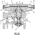
- FIG. 2A In the cross sections of figures 2A and 2B the flow direction through controller housing 4 from inflow opening 2 to outflow opening 3 is indicated with arrows 9.
- the gas pressure controller is shown from a different angle than in figure 1 , whereby the flow direction of gas through gas pressure controller 1 is reversed in the figure.
- a valve assembly 10 is arranged between inflow opening 2 and outflow opening 3. Such a valve assembly 10 is shown in more detail in figures 3A-4B .
- Figures 2A and 2B differ in that the diameter d, d' of valve assemblies 10 differs.
- Gas pressure controllers 1 of figures 2A and 2B are otherwise the same.
- Gas pressure controller 1 of for instance figure 2A can in this way be adapted to a lower desired capacity by integrally replacing valve assembly 10 with valve diameter d by a valve assembly 10 with a smaller valve diameter d' as shown in figure 2B .
- Gas pressure controller 1 of figure 2B can likewise be adapted to a higher desired capacity by arranging a valve assembly 10 with a greater valve diameter d.
- Valve assembly 10 comprises a valve seat 11 and a closing mechanism 12 therefor.
- Valve seat 11 and closing mechanism 12 can move relative to each other in order to enlarge, decrease or close an effective throughflow opening from inflow opening 2 to outflow opening 3.
- the gas pressure at outflow opening 3 can hereby be regulated by enlarging or decreasing the effective throughflow opening.
- Closing mechanism 12 and valve seat 11 are biased toward each other by means of spring 36 (see figure 2 ).
- Valve assembly 10 further comprises a control shaft 13 which is in this case connected to closing mechanism 12. In other embodiments the control shaft could be connected to valve seat 11 instead of to closing mechanism 12. In the embodiment shown in the figures control shaft 13 connects closing mechanism 12 to a membrane 14.
- Membrane 14 separates in known manner a first chamber 15 where a regulating pressure prevails and a second chamber 16 where the outlet pressure to be regulated prevails. Membrane 14 is deformed by differences in the regulating pressure and the outlet pressure, whereby control shaft 13 displaces closing mechanism 12 in the direction of or away from valve seat 11. The effective throughflow opening hereby becomes larger and the outlet pressure changes.
- a piston 18 is mounted on control shaft 13 relative to inflow channel 17 on the other side thereof than closing mechanism 12.
- the gas pressure in inflow channel 17 hereby presses on closing mechanism 12 and, in an opposite direction, on piston 18. Because the surface areas of piston 18 and closing mechanism 12 on which the pressure acts are approximately equal in the figures, the resultant force on control shaft 13 by the gas pressure in inflow channel 17 is roughly zero.
- the piston is connected by a rolling membrane 19 to valve seat 11 for movement relative to valve seat 11 in the length direction of control shaft 13.
- Rolling membrane 19 is substantially tubular and disposed coaxially with control shaft 13.
- Rolling membrane 19 closes second chamber 16 to gas from inflow channel 17. Because rolling membrane 19 can roll up and unroll in its length direction, piston 18 (and so control shaft 13 and closing mechanism 12) can move relative to valve seat 11.
- valve assembly 10 is releasably connectable to controller housing 4 and membrane 14.
- Membrane 14 is in this case received between a first shell 20 and a second shell 21 which together form the membrane housing 8.
- Second shell 21 is releasably connectable to first shell 20, in this example by fastening means formed by bolts 22.
- Second shell 21 is releasably connectable to first shell 20, in this example by fastening means formed by bolts 22.
- membrane 14 can also be released.
- Membrane 14 can optionally be releasably connectable to the control shaft by means of a nut 23.
- valve assembly 10 can be taken out of controller housing 4 by sliding valve assembly through an opening 24 in controller housing 4 and an opening 25 in membrane housing 8.
- valve assembly 10 has a flange 26 which is releasably connectable to controller housing 4 by screwing nuts onto threaded ends 27.
- Valve assembly 10 is hereby thus releasably connectable to both controller housing 4 and membrane housing 8. This has the advantage that valve assembly 10 can be placed in a simple manner in controller housing 4 or removed therefrom without damage being caused to valve seat 11, closing mechanism 12 or other parts of valve assembly 10 or controller housing 4. It is hereby also relatively simple to replace a valve assembly 10 with a first valve diameter by a valve assembly 10 with a second, different valve diameter. Controller housing 4 need not be replaced or modified for this purpose.
- control shaft 13 and closing mechanism 12 are provided in this example with mutually co-acting connecting members which are releasable from each other and which are formed by engaging openings 28, 29 in control shaft 13 and in a wall 30 extending along control shaft 13 from valve seat 11, and by a locking shaft 31.
- control shaft 31 is arranged in engaging openings 28, 29 so as to connect valve seat 11 to control shaft 13 and closing mechanism 12 via wall 30.
- Closing mechanism 12 can hereby not move relative to valve seat 11 when locking shaft 31 has been arranged.
- locking shaft 31 can be arranged so that closing mechanism 12 and valve seat 11 cannot move relative to each other during the insertion or removal, whereby damage can be prevented and the insertion or removal can take place more quickly and more easily.
- Both the opening 28 in control shaft 13 and the opening in wall 30 are in this case through-holes (see figure 5 for detail of the control shaft).
- Locking shaft 31 can hereby be pushed through the openings in order to secure control shaft 31 relative to valve seat 11.
- two openings 29 are arranged opposite each other relative to control shaft 13 so that locking shaft 31 can pass through control shaft 13 and engage at two locations on wall 30.
- Controller housing 4 is provided with at least one hole 32 through which locking shaft 31 is insertable and removable. Hole 32 is for this purpose aligned with openings 28, 29 in control shaft 13 and wall 30 when valve assembly 10 is connected to controller housing 4.
- controller housing 4 has two holes 32 on either side of the housing. Locking shaft 31 can hereby be slid through one of the holes 32 by being pushed through second hole 32 with a tool.
- Locking shaft 31 is shown in more detail in figure 6 .
- Locking shaft 31 has in this example a first segment 33 and a second segment 34 of differing cross-section.
- the cross-section of second segment 34 substantially corresponds to opening 28 in control shaft 13.
- Locking shaft 31 hereby fits clampingly to some extent in opening 28 of control shaft 13.
- Second segment 34 extends from a free end of locking shaft 31 to a point beyond half the length of locking shaft 31.
- First segment 33 extends over the rest of the length of locking shaft 31.
- the cross-section of first segment 33 is smaller than that of second segment 34.
- Locking shaft 31 can hereby be pushed over a relatively great part of its length, i.e. this part of first segment 33, relatively easily and/or with little or no friction through opening 28 of control shaft 13.
- An end zone 37 of the first segment is provided with an external screw thread with which locking shaft 31 can be screwed into an opening 29 in wall 30.
- a first opening 29 in wall 30 therefore has a diameter corresponding to the diameter of end zone 37 of locking shaft 31, and this same opening is provided with an internal screw thread.
- the other opening 28 lying opposite the first opening 29 has a diameter corresponding to that of second segment 34 of locking shaft 31 so that locking shaft 31 can be inserted from this opening 29 through control shaft 13 and then screwed into the opposite wall 30.
- locking shaft 31 provides the advantage that control shaft 13 is secured against rotation about its longitudinal axis relative to wall 30. Such a rotation could occur during the releasable connection of membrane 14 to control shaft 13, for instance by tightening the nut 23.
- the shown gas pressure controller 1 can be assembled according to the invention by first providing controller housing 4.
- Valve assembly 10, in which locking shaft 31 connects control shaft 13 to wall 30, can then be inserted into controller housing 4 and connected releasably thereto by means of flange 26 and threaded ends 27.
- First shell 20 of membrane housing 8 is releasably attached to the controller housing at the same time using flange 26 and threaded ends 27.
- Membrane 14 is subsequently connected releasably to control shaft 13 by means of nut 23.
- Membrane housing 8 is finally closed by connecting second shell 21 to first shell 20 by means of bolts 22.
- As final step locking shaft 31 is pushed out of gas pressure controller 1 through openings 28, 29 in control shaft 13 and wall 30 and holes 32 in controller housing 4.
- Control shaft 13, and so closing mechanism 12, can hereby move relative to valve seat 11, whereby the valve can operate.
- Controller housing 4 optionally has a bottom cover 35 which can be temporarily removed so that spring 36 is left clear before insertion of valve assembly 10 into controller housing 4.
- Valve assembly 10 need not hereby be inserted counter to the spring pressure of spring 36.
- a locking shaft 31 can first be arranged through holes 32 in controller housing 4 in order to secure control shaft 13 relative to valve seat 11. Valve assembly 10 can then be released by at least partially releasing membrane housing 8 and releasing membrane 14. A new or other valve assembly 10 also having a locking shaft 31 therein can then be arranged as specified above.
- Figure 7 shows a flow diagram of a method 100 for assembling a gas pressure controller.
- the method comprises a first step 101a of providing a controller housing 4 having an inflow opening 2 and an outflow opening 3, and a step 101b of providing a valve assembly with the above specified features. These steps are followed by a second step 102 of releasably connecting a valve assembly 10 between inflow and outflow openings 2, 3.
- the method further comprises a step 103 of connecting control shaft 13 releasably to a membrane 14.
- Membrane 14 further opens and/or closes valve assembly 10 as above via control shaft 13. Controller housing 4 is then closed, optionally with membrane housing 8, or made ready for use in any suitable manner.
- step 102 takes place by inserting valve assembly 10 at least partially through an opening in controller housing 4 intended for the purpose, and valve assembly 10 is partially inserted into membrane housing 8 through an opening for passage of valve assembly 10.
- the other of closing mechanism 11 and valve seat 12 is in this case connected releasably to control shaft 13 before step 102, i.e. connection takes place outside controller housing 4.
- the connection of the other of closing mechanism 11 and valve seat 12 to control shaft 13 is optionally released after step 103, i.e. after valve assembly 10 has been placed in controller housing 4.
- Figure 8 shows a flow diagram 105 for replacing a valve assembly 10 in a gas pressure controller.
- a gas pressure controller 1 can first of all be provided for this purpose, after which in step 104 the valve assembly 10 is released from controller housing 4, and for which purpose membrane 14 and at least a part of membrane housing 8 are optionally released from controller housing 4.
- this method can be used by means of the optional step 104 to replace a valve assembly 10, for instance with a smaller valve diameter d', in a gas pressure controller 1 by an assembly with a larger valve diameter d.
Landscapes
- Engineering & Computer Science (AREA)
- Physics & Mathematics (AREA)
- Power Engineering (AREA)
- Fluid Mechanics (AREA)
- General Physics & Mathematics (AREA)
- Automation & Control Theory (AREA)
- Control Of Fluid Pressure (AREA)
- Lift Valve (AREA)
Claims (15)
- Gasdruckregler, aufweisend:- ein Reglergehäuse mit einer Einlassöffnung und einer Auslassöffnung;- eine Membran;- eine zwischen der Einlassöffnung und der Auslassöffnung angeordnete Ventilbaugruppe, welche aufweist:- einen Ventilsitz und einen relativ dazu beweglichen Schließmechanismus zum Einstellen und/oder Schließen einer effektiven Durchflussöffnung zwischen Einlassöffnung und Auslassöffnung;und- einen Regelschaft, der entweder mit dem Schließmechanismus oder dem Ventilsitz verbunden ist, und der entweder den Schließmechanismus oder den Ventilsitz mit der Membran verbindet, wobei die Membran ferner so ausgebildet ist, dass sie das Ventil über den Regelschaft in Abhängigkeit von dem auf die Membran ausgeübten Gasdruck öffnet und/oder schließt,dadurch gekennzeichnet, dass die Ventilbaugruppe als Ganzes mit dem Steuergehäuse und der Membran lösbar verbindbar ist, ohne dass die Komponenten der Ventilbaugruppe voneinander getrennt werden müssen.
- Gasdruckregler nach Anspruch 1, wobei die Ventilbaugruppe über eine dafür vorgesehene Öffnung im Reglergehäuse zumindest teilweise in das Reglergehäuse eingesetzt werden kann.
- Gasdruckregler nach einem der vorherigen Ansprüche, wobei die Membran in einem Membrangehäuse angeordnet ist und das Membrangehäuse mindestens eine Öffnung für die Durchführung der Ventilbaugruppe aufweist,
wobei vorzugsweise die Membran und das Membrangehäuse zumindest teilweise lösbar mit dem Reglergehäuse verbindbar sind, um die Öffnung im Membrangehäuse für die Durchführung der Ventilbaugruppe freizuhalten. - Gasdruckregler nach einem der vorherigen Ansprüche, wobei der Regelschaft und der andere der beiden Mechanismen, Schließmechanismus beziehungsweise Ventilsitz, mit miteinander zusammenwirkenden voneinander lösbaren Verbindungselementen versehen sind, um den Regelschaft und den anderen der beiden Mechanismen, Schließmechanismus und Ventilsitz, lösbar miteinander zu verbinden.
- Gasdruckregler nach Anspruch 4, wobei die miteinander zusammenwirkenden Verbindungselemente durch folgende Elemente gebildet werden:- Eingriffsöffnungen in dem Regelschaft und mindestens eine Wandung, die mit dem anderen der beiden Mechanismen, Schließmechanismus beziehungsweise Ventilsitz, verbunden ist, und die sich entlang dem Regelschaft von dem anderen der beiden Mechanismen, Schließmechanismus beziehungsweise Ventilsitz, aus erstreckt; und- einen Verriegelungsstift, der lösbar in den Eingriffsöffnungen angeordnet werden kann, um den Regelschaft und den anderen der beiden Mechanismen, Schließmechanismus beziehungsweise Ventilsitz, lösbar miteinander zu verbinden, wobei die Eingriffsöffnungen vorzugsweise durch Durchgangslöcher gebildet sind, in die der Verriegelungsstift eingeschoben und/oder eingeschraubt werden kann.
- Gasdruckregler nach Anspruch 5, wobei die mindestens eine Wandung in Bezug auf den Regelschaft mit zwei sich gegenüberliegenden Eingriffsöffnungen versehen ist.
- Gasdruckregler nach Anspruch 5, wobei das Reglergehäuse mindestens ein Loch aufweist, durch das der Verriegelungsstift zumindest teilweise entfernbar ist, um die Verbindungselemente voneinander zu trennen, wenn die Ventilbaugruppe mit dem Reglergehäuse verbunden ist.
- Gasdruckregler nach einem der Ansprüche 5 bis 7, wobei der Verriegelungsstift in seiner Längsrichtung ein erstes Segment mit einem ersten Querschnitt und ein zweites Segment mit einem zweiten Querschnitt aufweist, wobei die Abmessungen des Querschnitts des zweiten Segments der Eingriffsöffnung in dem Regelschaft entsprechen und die Abmessungen des Querschnitts des ersten Segments kleiner sind als die Abmessungen des Querschnitts des zweiten Segments.
- Gasdruckregler nach einem der vorherigen Ansprüche, wobei der Regelschaft mit dem Schließmechanismus verbunden ist,wobei vorzugsweise die Ventilbaugruppe ferner einen mit dem Regelschaft verbundenen Kolben aufweist, der sich bei mit dem Reglergehäuse verbundener Ventilbaugruppe auf der anderen Seite der Einlassöffnung befindet als der Schließmechanismus, und/oderwobei der Kolben mit dem Ventilsitz über eine Rollmembran beweglich verbunden ist.
- Gasdruckregler nach einem der Ansprüche 2 bis 9, wobei der Ventilsitz einen ersten Ventil-Innendurchmesser und die Ventilbaugruppe einen Außendurchmesser aufweist, der einem Durchmesser der Öffnung im Reglergehäuse entspricht, und wobei ferner eine zweite Ventilbaugruppe als Ersatz für die Ventilbaugruppe vorgesehen ist, wobei der Außendurchmesser der zweiten Ventilbaugruppe ebenfalls dem Durchmesser der Öffnung im Reglergehäuse entspricht, und wobei die zweite Ventilbaugruppe einen Ventilsitz mit einem zweiten Ventil-Innendurchmesser aufweist, der sich von dem ersten Ventil-Innendurchmesser unterscheidet.
- Ventilbaugruppe, die für die Verwendung in einem Gasdruckregler nach einem der vorherigen Ansprüche geeignet und bestimmt ist.
- Verfahren zum Zusammenbau eines Gasdruckreglers, beispielsweise nach einem der vorherigen Ansprüche, aufweisend die folgenden Schritte:a) Bereitstellen eines Reglergehäuses mit einer Einlassöffnung und einer Auslassöffnung;b) Einbauen einer Ventilbaugruppe als Ganzes zwischen der Einlassöffnung und der Auslassöffnung ohne die Komponenten der Ventilbaugruppe voneinander zu trennen, wobei die Ventilbaugruppe aufweist:- einen Ventilsitz und einen relativ dazu beweglichen Schließmechanismus zum Einstellen und/oder Schließen einer effektiven Durchflussöffnung zwischen der Einlassöffnung und der Auslassöffnung; und- einen Regelschaft, der entweder mit dem Schließmechanismus oder dem Ventilsitz verbunden ist; sowiec) lösbares Verbinden des Regelschaftes mit einer Membran,wobei die Membran ferner die Ventilbaugruppe über den Regelschaft in Abhängigkeit von dem auf die Membran ausgeübten Gasdruck öffnet und/oder schließt.
- Verfahren nach Anspruch 12, wobei Schritt b) durch zumindest teilweises Einsetzen der Ventilbaugruppe in eine dafür vorgesehene Öffnung des Reglergehäuses erfolgt,
wobei vorzugsweise die Ventilbaugruppe durch eine Öffnung zur Durchführung der Ventilbaugruppe zumindest teilweise in das Membrangehäuse eingesetzt wird. - Verfahren nach einem der Ansprüche 12 bis 13, wobei der andere der beiden Mechanismen, Schließmechanismus beziehungsweise Ventilsitz, vor Schritt b) lösbar mit dem Regelschaft verbunden und optional nach Schritt c) entfernt wird.
- Verfahren zum Auswechseln einer Ventilbaugruppe in einem Gasdruckregler nach Anspruch 10, welches die folgenden Schritte aufweist:d) Entnehmen der Ventilbaugruppe aus dem Reglergehäuse und optional Entfernen der Membran und zumindest eines Teils des Membrangehäuses aus dem Reglergehäuse; unde) Zusammenbauen des Gasdruckreglers mit der zweiten Ventilbaugruppe nach einem der Ansprüche 12 bis 14.
Applications Claiming Priority (3)
| Application Number | Priority Date | Filing Date | Title |
|---|---|---|---|
| NL2021402A NL2021402B1 (nl) | 2018-07-27 | 2018-07-27 | Gasdrukregelaar, klepsamenstel en werkwijze voor het assembleren van een gasdrukregelaar |
| EP18201043.9A EP3441843B1 (de) | 2018-07-27 | 2018-10-17 | Gasdruckregler, ventilanordnung und verfahren zur montage eines gasdruckreglers |
| PCT/NL2019/050497 WO2020022904A1 (en) | 2018-07-27 | 2019-07-26 | Gas pressure controller, valve assembly and method of assembling a gas pressure controller |
Publications (2)
| Publication Number | Publication Date |
|---|---|
| EP3830665A1 EP3830665A1 (de) | 2021-06-09 |
| EP3830665B1 true EP3830665B1 (de) | 2022-07-20 |
Family
ID=64023941
Family Applications (2)
| Application Number | Title | Priority Date | Filing Date |
|---|---|---|---|
| EP18201043.9A Active EP3441843B1 (de) | 2018-07-27 | 2018-10-17 | Gasdruckregler, ventilanordnung und verfahren zur montage eines gasdruckreglers |
| EP19756003.0A Active EP3830665B1 (de) | 2018-07-27 | 2019-07-26 | Gasdruckregler, ventilanordnung und verfahren zur montage eines gasdruckreglers |
Family Applications Before (1)
| Application Number | Title | Priority Date | Filing Date |
|---|---|---|---|
| EP18201043.9A Active EP3441843B1 (de) | 2018-07-27 | 2018-10-17 | Gasdruckregler, ventilanordnung und verfahren zur montage eines gasdruckreglers |
Country Status (4)
| Country | Link |
|---|---|
| EP (2) | EP3441843B1 (de) |
| CN (1) | CN112513769A (de) |
| NL (1) | NL2021402B1 (de) |
| WO (1) | WO2020022904A1 (de) |
Family Cites Families (7)
| Publication number | Priority date | Publication date | Assignee | Title |
|---|---|---|---|---|
| DE1039332B (de) * | 1953-12-28 | 1958-09-18 | Gerdts Gustav F Kg | Mehrstufige Regelduese |
| DE29808322U1 (de) * | 1998-05-12 | 1998-12-17 | Bien, Tanja, 63637 Jossgrund | Absperrorgan für Fluide |
| DE10220789B4 (de) * | 2002-05-10 | 2008-05-29 | Haldex Brake Products Gmbh | Druckluftaufbereitungseinrichtung für Kfz-Druckluftanlagen |
| CN102032370B (zh) * | 2011-01-13 | 2012-10-17 | 天津市益斯达燃气设备有限公司 | 一种超压切断阀 |
| US9086702B2 (en) * | 2011-07-01 | 2015-07-21 | Emerson Process Management Regulator Technologies, Inc. | Pressure-balanced fluid pressure regulators |
| DE102012207265B3 (de) * | 2012-05-02 | 2013-09-19 | Gemü Gebr. Müller Apparatebau Gmbh & Co. Kommanditgesellschaft | Absperrorgan für Fluide sowie Druckstück für ein derartiges Absperrorgan |
| DE102013001979A1 (de) * | 2013-02-05 | 2014-08-07 | Eisenmann Ag | Druckregler |
-
2018
- 2018-07-27 NL NL2021402A patent/NL2021402B1/nl not_active IP Right Cessation
- 2018-10-17 EP EP18201043.9A patent/EP3441843B1/de active Active
-
2019
- 2019-07-26 WO PCT/NL2019/050497 patent/WO2020022904A1/en not_active Ceased
- 2019-07-26 CN CN201980050266.8A patent/CN112513769A/zh active Pending
- 2019-07-26 EP EP19756003.0A patent/EP3830665B1/de active Active
Also Published As
| Publication number | Publication date |
|---|---|
| WO2020022904A1 (en) | 2020-01-30 |
| EP3441843A2 (de) | 2019-02-13 |
| NL2021402B1 (nl) | 2020-01-31 |
| EP3441843B1 (de) | 2021-07-14 |
| EP3830665A1 (de) | 2021-06-09 |
| EP3441843A3 (de) | 2019-05-08 |
| CN112513769A (zh) | 2021-03-16 |
Similar Documents
| Publication | Publication Date | Title |
|---|---|---|
| US8267110B2 (en) | Gas pressure regulator and method for assembling and disassembling the regulator | |
| EP2191181B1 (de) | Vorrichtung und verfahren für die vorrangssteuerung eines linearantriebs | |
| JP5511673B2 (ja) | 流量制御装置および流量制御装置を組み立てるための方法 | |
| DE3153338C2 (en) | Actuating device for a valve | |
| US10228073B2 (en) | Adjustable fail-safe rotary spring operator with a retaining band | |
| CN103697219B (zh) | 具有阀盘制动器组件的紧急切断安全装置 | |
| EP1793299B1 (de) | Doppel-Gasdruckregler für Haushaltsgeräte | |
| US6015134A (en) | Pneumatic actuator assembly | |
| US20080078460A1 (en) | Positioning Device for Pressure Regulator | |
| US10215291B2 (en) | Regulating device | |
| US7472716B2 (en) | Valve packing removal device | |
| EP3809232B1 (de) | Druckregelventil | |
| EP3441843B1 (de) | Gasdruckregler, ventilanordnung und verfahren zur montage eines gasdruckreglers | |
| WO2013177366A1 (en) | Valve actuator system | |
| EP2693287B1 (de) | Ventilanordnung zur Regelung des Durchflusses einer Heiz- oder Kühlflüssigkeit und Werkzeuganordnung zum Auswechseln von mindestens einem Teil einer derartigen Ventilanordnung | |
| EP2481962B1 (de) | Ventilanordnung zur Regelung des Durchflusses einer Heiz- oder Kühlflüssigkeit und Werkzeuganordnung zum Auswechseln von mindestens einem Teil einer derartigen Ventilanordnung | |
| JP2582448Y2 (ja) | 減圧弁 | |
| DE102018128549B4 (de) | Einlassventil, Luftfeder oder Luftfederdämpfer mit einem derartigen Einlassventil sowie Verfahren zur Befestigung eines Einlassventils | |
| DE3235274C2 (de) | Sicherheitsvorrichtung für Stellgeräte, wie z.B. Druckminderer | |
| EP4660497A1 (de) | Druckentlastungsventile für flugzeuge | |
| EP3434947B1 (de) | Anordnung mit einer industrieventileinheit, einem aktuator und einem verbinder, der die ventileinheit lösbar mit dem aktuator verbindet | |
| DE147011C (de) | ||
| WO2025024418A1 (en) | Externally adjustable pressure modulating valve | |
| JP5451489B2 (ja) | 圧力制御装置及びその連結方法 |
Legal Events
| Date | Code | Title | Description |
|---|---|---|---|
| STAA | Information on the status of an ep patent application or granted ep patent |
Free format text: STATUS: UNKNOWN |
|
| STAA | Information on the status of an ep patent application or granted ep patent |
Free format text: STATUS: THE INTERNATIONAL PUBLICATION HAS BEEN MADE |
|
| PUAI | Public reference made under article 153(3) epc to a published international application that has entered the european phase |
Free format text: ORIGINAL CODE: 0009012 |
|
| STAA | Information on the status of an ep patent application or granted ep patent |
Free format text: STATUS: REQUEST FOR EXAMINATION WAS MADE |
|
| 17P | Request for examination filed |
Effective date: 20210224 |
|
| AK | Designated contracting states |
Kind code of ref document: A1 Designated state(s): AL AT BE BG CH CY CZ DE DK EE ES FI FR GB GR HR HU IE IS IT LI LT LU LV MC MK MT NL NO PL PT RO RS SE SI SK SM TR |
|
| DAV | Request for validation of the european patent (deleted) | ||
| DAX | Request for extension of the european patent (deleted) | ||
| REG | Reference to a national code |
Ref country code: DE Ref legal event code: R079 Ref document number: 602019017256 Country of ref document: DE Free format text: PREVIOUS MAIN CLASS: G05D0016180000 Ipc: G05D0016160000 |
|
| GRAP | Despatch of communication of intention to grant a patent |
Free format text: ORIGINAL CODE: EPIDOSNIGR1 |
|
| STAA | Information on the status of an ep patent application or granted ep patent |
Free format text: STATUS: GRANT OF PATENT IS INTENDED |
|
| RIC1 | Information provided on ipc code assigned before grant |
Ipc: G05D 16/16 20060101AFI20220128BHEP |
|
| INTG | Intention to grant announced |
Effective date: 20220302 |
|
| GRAS | Grant fee paid |
Free format text: ORIGINAL CODE: EPIDOSNIGR3 |
|
| GRAA | (expected) grant |
Free format text: ORIGINAL CODE: 0009210 |
|
| STAA | Information on the status of an ep patent application or granted ep patent |
Free format text: STATUS: THE PATENT HAS BEEN GRANTED |
|
| AK | Designated contracting states |
Kind code of ref document: B1 Designated state(s): AL AT BE BG CH CY CZ DE DK EE ES FI FR GB GR HR HU IE IS IT LI LT LU LV MC MK MT NL NO PL PT RO RS SE SI SK SM TR |
|
| REG | Reference to a national code |
Ref country code: CH Ref legal event code: EP |
|
| REG | Reference to a national code |
Ref country code: DE Ref legal event code: R096 Ref document number: 602019017256 Country of ref document: DE |
|
| REG | Reference to a national code |
Ref country code: AT Ref legal event code: REF Ref document number: 1505940 Country of ref document: AT Kind code of ref document: T Effective date: 20220815 |
|
| REG | Reference to a national code |
Ref country code: IE Ref legal event code: FG4D |
|
| REG | Reference to a national code |
Ref country code: NL Ref legal event code: FP |
|
| REG | Reference to a national code |
Ref country code: LT Ref legal event code: MG9D |
|
| PG25 | Lapsed in a contracting state [announced via postgrant information from national office to epo] |
Ref country code: SE Free format text: LAPSE BECAUSE OF FAILURE TO SUBMIT A TRANSLATION OF THE DESCRIPTION OR TO PAY THE FEE WITHIN THE PRESCRIBED TIME-LIMIT Effective date: 20220720 Ref country code: RS Free format text: LAPSE BECAUSE OF FAILURE TO SUBMIT A TRANSLATION OF THE DESCRIPTION OR TO PAY THE FEE WITHIN THE PRESCRIBED TIME-LIMIT Effective date: 20220720 Ref country code: PT Free format text: LAPSE BECAUSE OF FAILURE TO SUBMIT A TRANSLATION OF THE DESCRIPTION OR TO PAY THE FEE WITHIN THE PRESCRIBED TIME-LIMIT Effective date: 20221121 Ref country code: NO Free format text: LAPSE BECAUSE OF FAILURE TO SUBMIT A TRANSLATION OF THE DESCRIPTION OR TO PAY THE FEE WITHIN THE PRESCRIBED TIME-LIMIT Effective date: 20221020 Ref country code: LV Free format text: LAPSE BECAUSE OF FAILURE TO SUBMIT A TRANSLATION OF THE DESCRIPTION OR TO PAY THE FEE WITHIN THE PRESCRIBED TIME-LIMIT Effective date: 20220720 Ref country code: LT Free format text: LAPSE BECAUSE OF FAILURE TO SUBMIT A TRANSLATION OF THE DESCRIPTION OR TO PAY THE FEE WITHIN THE PRESCRIBED TIME-LIMIT Effective date: 20220720 Ref country code: FI Free format text: LAPSE BECAUSE OF FAILURE TO SUBMIT A TRANSLATION OF THE DESCRIPTION OR TO PAY THE FEE WITHIN THE PRESCRIBED TIME-LIMIT Effective date: 20220720 Ref country code: ES Free format text: LAPSE BECAUSE OF FAILURE TO SUBMIT A TRANSLATION OF THE DESCRIPTION OR TO PAY THE FEE WITHIN THE PRESCRIBED TIME-LIMIT Effective date: 20220720 |
|
| REG | Reference to a national code |
Ref country code: AT Ref legal event code: MK05 Ref document number: 1505940 Country of ref document: AT Kind code of ref document: T Effective date: 20220720 |
|
| PG25 | Lapsed in a contracting state [announced via postgrant information from national office to epo] |
Ref country code: PL Free format text: LAPSE BECAUSE OF FAILURE TO SUBMIT A TRANSLATION OF THE DESCRIPTION OR TO PAY THE FEE WITHIN THE PRESCRIBED TIME-LIMIT Effective date: 20220720 Ref country code: IS Free format text: LAPSE BECAUSE OF FAILURE TO SUBMIT A TRANSLATION OF THE DESCRIPTION OR TO PAY THE FEE WITHIN THE PRESCRIBED TIME-LIMIT Effective date: 20221120 Ref country code: HR Free format text: LAPSE BECAUSE OF FAILURE TO SUBMIT A TRANSLATION OF THE DESCRIPTION OR TO PAY THE FEE WITHIN THE PRESCRIBED TIME-LIMIT Effective date: 20220720 Ref country code: GR Free format text: LAPSE BECAUSE OF FAILURE TO SUBMIT A TRANSLATION OF THE DESCRIPTION OR TO PAY THE FEE WITHIN THE PRESCRIBED TIME-LIMIT Effective date: 20221021 |
|
| REG | Reference to a national code |
Ref country code: DE Ref legal event code: R097 Ref document number: 602019017256 Country of ref document: DE |
|
| PG25 | Lapsed in a contracting state [announced via postgrant information from national office to epo] |
Ref country code: SM Free format text: LAPSE BECAUSE OF FAILURE TO SUBMIT A TRANSLATION OF THE DESCRIPTION OR TO PAY THE FEE WITHIN THE PRESCRIBED TIME-LIMIT Effective date: 20220720 Ref country code: RO Free format text: LAPSE BECAUSE OF FAILURE TO SUBMIT A TRANSLATION OF THE DESCRIPTION OR TO PAY THE FEE WITHIN THE PRESCRIBED TIME-LIMIT Effective date: 20220720 Ref country code: MC Free format text: LAPSE BECAUSE OF FAILURE TO SUBMIT A TRANSLATION OF THE DESCRIPTION OR TO PAY THE FEE WITHIN THE PRESCRIBED TIME-LIMIT Effective date: 20220720 Ref country code: LU Free format text: LAPSE BECAUSE OF NON-PAYMENT OF DUE FEES Effective date: 20220726 Ref country code: DK Free format text: LAPSE BECAUSE OF FAILURE TO SUBMIT A TRANSLATION OF THE DESCRIPTION OR TO PAY THE FEE WITHIN THE PRESCRIBED TIME-LIMIT Effective date: 20220720 Ref country code: CZ Free format text: LAPSE BECAUSE OF FAILURE TO SUBMIT A TRANSLATION OF THE DESCRIPTION OR TO PAY THE FEE WITHIN THE PRESCRIBED TIME-LIMIT Effective date: 20220720 Ref country code: AT Free format text: LAPSE BECAUSE OF FAILURE TO SUBMIT A TRANSLATION OF THE DESCRIPTION OR TO PAY THE FEE WITHIN THE PRESCRIBED TIME-LIMIT Effective date: 20220720 |
|
| PLBE | No opposition filed within time limit |
Free format text: ORIGINAL CODE: 0009261 |
|
| STAA | Information on the status of an ep patent application or granted ep patent |
Free format text: STATUS: NO OPPOSITION FILED WITHIN TIME LIMIT |
|
| PG25 | Lapsed in a contracting state [announced via postgrant information from national office to epo] |
Ref country code: SK Free format text: LAPSE BECAUSE OF FAILURE TO SUBMIT A TRANSLATION OF THE DESCRIPTION OR TO PAY THE FEE WITHIN THE PRESCRIBED TIME-LIMIT Effective date: 20220720 Ref country code: EE Free format text: LAPSE BECAUSE OF FAILURE TO SUBMIT A TRANSLATION OF THE DESCRIPTION OR TO PAY THE FEE WITHIN THE PRESCRIBED TIME-LIMIT Effective date: 20220720 |
|
| 26N | No opposition filed |
Effective date: 20230421 |
|
| PG25 | Lapsed in a contracting state [announced via postgrant information from national office to epo] |
Ref country code: AL Free format text: LAPSE BECAUSE OF FAILURE TO SUBMIT A TRANSLATION OF THE DESCRIPTION OR TO PAY THE FEE WITHIN THE PRESCRIBED TIME-LIMIT Effective date: 20220720 |
|
| PG25 | Lapsed in a contracting state [announced via postgrant information from national office to epo] |
Ref country code: IE Free format text: LAPSE BECAUSE OF NON-PAYMENT OF DUE FEES Effective date: 20220726 |
|
| PG25 | Lapsed in a contracting state [announced via postgrant information from national office to epo] |
Ref country code: SI Free format text: LAPSE BECAUSE OF FAILURE TO SUBMIT A TRANSLATION OF THE DESCRIPTION OR TO PAY THE FEE WITHIN THE PRESCRIBED TIME-LIMIT Effective date: 20220720 |
|
| PG25 | Lapsed in a contracting state [announced via postgrant information from national office to epo] |
Ref country code: MK Free format text: LAPSE BECAUSE OF FAILURE TO SUBMIT A TRANSLATION OF THE DESCRIPTION OR TO PAY THE FEE WITHIN THE PRESCRIBED TIME-LIMIT Effective date: 20220720 Ref country code: CY Free format text: LAPSE BECAUSE OF FAILURE TO SUBMIT A TRANSLATION OF THE DESCRIPTION OR TO PAY THE FEE WITHIN THE PRESCRIBED TIME-LIMIT Effective date: 20220720 |
|
| PG25 | Lapsed in a contracting state [announced via postgrant information from national office to epo] |
Ref country code: HU Free format text: LAPSE BECAUSE OF FAILURE TO SUBMIT A TRANSLATION OF THE DESCRIPTION OR TO PAY THE FEE WITHIN THE PRESCRIBED TIME-LIMIT; INVALID AB INITIO Effective date: 20190726 |
|
| PG25 | Lapsed in a contracting state [announced via postgrant information from national office to epo] |
Ref country code: BG Free format text: LAPSE BECAUSE OF FAILURE TO SUBMIT A TRANSLATION OF THE DESCRIPTION OR TO PAY THE FEE WITHIN THE PRESCRIBED TIME-LIMIT Effective date: 20220720 |
|
| PG25 | Lapsed in a contracting state [announced via postgrant information from national office to epo] |
Ref country code: MT Free format text: LAPSE BECAUSE OF FAILURE TO SUBMIT A TRANSLATION OF THE DESCRIPTION OR TO PAY THE FEE WITHIN THE PRESCRIBED TIME-LIMIT Effective date: 20220720 |
|
| PGFP | Annual fee paid to national office [announced via postgrant information from national office to epo] |
Ref country code: GB Payment date: 20240729 Year of fee payment: 6 |
|
| PGFP | Annual fee paid to national office [announced via postgrant information from national office to epo] |
Ref country code: BE Payment date: 20240729 Year of fee payment: 6 |
|
| PGFP | Annual fee paid to national office [announced via postgrant information from national office to epo] |
Ref country code: FR Payment date: 20240725 Year of fee payment: 6 |
|
| PGFP | Annual fee paid to national office [announced via postgrant information from national office to epo] |
Ref country code: CH Payment date: 20240801 Year of fee payment: 6 |
|
| PGFP | Annual fee paid to national office [announced via postgrant information from national office to epo] |
Ref country code: NL Payment date: 20250726 Year of fee payment: 7 |
|
| PGFP | Annual fee paid to national office [announced via postgrant information from national office to epo] |
Ref country code: DE Payment date: 20250729 Year of fee payment: 7 |
|
| PGFP | Annual fee paid to national office [announced via postgrant information from national office to epo] |
Ref country code: IT Payment date: 20250721 Year of fee payment: 7 Ref country code: TR Payment date: 20250711 Year of fee payment: 7 |
|
| REG | Reference to a national code |
Ref country code: CH Ref legal event code: H13 Free format text: ST27 STATUS EVENT CODE: U-0-0-H10-H13 (AS PROVIDED BY THE NATIONAL OFFICE) Effective date: 20260224 |
|
| GBPC | Gb: european patent ceased through non-payment of renewal fee |
Effective date: 20250726 |
|
| REG | Reference to a national code |
Ref country code: BE Ref legal event code: MM Effective date: 20250731 |
|
| PG25 | Lapsed in a contracting state [announced via postgrant information from national office to epo] |
Ref country code: GB Free format text: LAPSE BECAUSE OF NON-PAYMENT OF DUE FEES Effective date: 20250726 |
|
| PG25 | Lapsed in a contracting state [announced via postgrant information from national office to epo] |
Ref country code: BE Free format text: LAPSE BECAUSE OF NON-PAYMENT OF DUE FEES Effective date: 20250731 |
|
| PG25 | Lapsed in a contracting state [announced via postgrant information from national office to epo] |
Ref country code: FR Free format text: LAPSE BECAUSE OF NON-PAYMENT OF DUE FEES Effective date: 20250731 |
|
| PG25 | Lapsed in a contracting state [announced via postgrant information from national office to epo] |
Ref country code: CH Free format text: LAPSE BECAUSE OF NON-PAYMENT OF DUE FEES Effective date: 20250731 |