EP3831114B1 - System und verfahren zur unterstützung von burst-kommunikationen in drahtloskommunikationssystemen - Google Patents
System und verfahren zur unterstützung von burst-kommunikationen in drahtloskommunikationssystemen Download PDFInfo
- Publication number
- EP3831114B1 EP3831114B1 EP19846273.1A EP19846273A EP3831114B1 EP 3831114 B1 EP3831114 B1 EP 3831114B1 EP 19846273 A EP19846273 A EP 19846273A EP 3831114 B1 EP3831114 B1 EP 3831114B1
- Authority
- EP
- European Patent Office
- Prior art keywords
- cot
- slot
- initial
- initial block
- access node
- Prior art date
- Legal status (The legal status is an assumption and is not a legal conclusion. Google has not performed a legal analysis and makes no representation as to the accuracy of the status listed.)
- Active
Links
Images



Classifications
-
- H—ELECTRICITY
- H04—ELECTRIC COMMUNICATION TECHNIQUE
- H04L—TRANSMISSION OF DIGITAL INFORMATION, e.g. TELEGRAPHIC COMMUNICATION
- H04L5/00—Arrangements affording multiple use of the transmission path
- H04L5/003—Arrangements for allocating sub-channels of the transmission path
- H04L5/0048—Allocation of pilot signals, i.e. of signals known to the receiver
- H04L5/0051—Allocation of pilot signals, i.e. of signals known to the receiver of dedicated pilots, i.e. pilots destined for a single user or terminal
-
- H—ELECTRICITY
- H04—ELECTRIC COMMUNICATION TECHNIQUE
- H04W—WIRELESS COMMUNICATION NETWORKS
- H04W74/00—Wireless channel access
- H04W74/08—Non-scheduled access, e.g. ALOHA
- H04W74/0808—Non-scheduled access, e.g. ALOHA using carrier sensing, e.g. carrier sense multiple access [CSMA]
- H04W74/0816—Non-scheduled access, e.g. ALOHA using carrier sensing, e.g. carrier sense multiple access [CSMA] with collision avoidance
-
- H—ELECTRICITY
- H04—ELECTRIC COMMUNICATION TECHNIQUE
- H04L—TRANSMISSION OF DIGITAL INFORMATION, e.g. TELEGRAPHIC COMMUNICATION
- H04L27/00—Modulated-carrier systems
- H04L27/0006—Assessment of spectral gaps suitable for allocating digitally modulated signals, e.g. for carrier allocation in cognitive radio
-
- H—ELECTRICITY
- H04—ELECTRIC COMMUNICATION TECHNIQUE
- H04L—TRANSMISSION OF DIGITAL INFORMATION, e.g. TELEGRAPHIC COMMUNICATION
- H04L5/00—Arrangements affording multiple use of the transmission path
- H04L5/003—Arrangements for allocating sub-channels of the transmission path
- H04L5/0053—Allocation of signalling, i.e. of overhead other than pilot signals
-
- H—ELECTRICITY
- H04—ELECTRIC COMMUNICATION TECHNIQUE
- H04L—TRANSMISSION OF DIGITAL INFORMATION, e.g. TELEGRAPHIC COMMUNICATION
- H04L5/00—Arrangements affording multiple use of the transmission path
- H04L5/0091—Signalling for the administration of the divided path, e.g. signalling of configuration information
-
- H—ELECTRICITY
- H04—ELECTRIC COMMUNICATION TECHNIQUE
- H04W—WIRELESS COMMUNICATION NETWORKS
- H04W72/00—Local resource management
- H04W72/04—Wireless resource allocation
- H04W72/044—Wireless resource allocation based on the type of the allocated resource
- H04W72/0446—Resources in time domain, e.g. slots or frames
-
- H—ELECTRICITY
- H04—ELECTRIC COMMUNICATION TECHNIQUE
- H04W—WIRELESS COMMUNICATION NETWORKS
- H04W72/00—Local resource management
- H04W72/12—Wireless traffic scheduling
-
- H—ELECTRICITY
- H04—ELECTRIC COMMUNICATION TECHNIQUE
- H04W—WIRELESS COMMUNICATION NETWORKS
- H04W74/00—Wireless channel access
- H04W74/002—Transmission of channel access control information
-
- H—ELECTRICITY
- H04—ELECTRIC COMMUNICATION TECHNIQUE
- H04W—WIRELESS COMMUNICATION NETWORKS
- H04W74/00—Wireless channel access
- H04W74/08—Non-scheduled access, e.g. ALOHA
- H04W74/0808—Non-scheduled access, e.g. ALOHA using carrier sensing, e.g. carrier sense multiple access [CSMA]
Definitions
- the present disclosure relates generally to a system and method for wireless communications, and, in particular aspects, to a system and method for supporting bursty communications in wireless communications systems.
- LBT listen before talk
- the transmitting device has to listen to the communications channel (or channels) to ascertain that the communications channel is idle before it can transmit. If the communications channel is not idle, the transmitting device cannot transmit.
- the uncertainty related to the availability of the communications channel may present a problem for communications systems with scheduled communications because the communications generally have to be scheduled and at least partially generated before the transmitting device is able to determine if the communications channel is available. Therefore, if the communications channel is unavailable, at least some of the scheduled communications cannot take place and the communications that has been generated is wasted. Therefore, there is a need for systems and methods for ensuring fair and efficient usage of the unlicensed spectrum.
- Example aspects provide a system and method for supporting bursty communications in wireless communications systems.
- FIG. 1 illustrates an example wireless communications system 100.
- Communications system 100 includes an access node 105 serving a plurality of user equipments (UEs), including UEs 110, 112, 114, and 116.
- Access node 105 establishes downlink and uplink connections with the UEs.
- the downlink connections carry data from access node 105 to the UEs and the uplink connections carry data from the UEs to access node 105.
- Data carried over the downlink or uplink connections may include data communicated between the UEs and services (not shown) by way of a backhaul network.
- Wireless access may be provided in accordance with one or more wireless communications protocols, e.g., the Third Generation Partnership Project (3GPP) Long Term Evolution (LTE), LTE Advanced (LTE-A), Fifth Generation (5G) New Radio (NR), high speed packet access (HSPA), IEEE 802.11, and so on.
- 3GPP Third Generation Partnership Project
- LTE Long Term Evolution
- LTE-A LTE Advanced
- 5G Fifth Generation
- NR High Speed Packet Radio
- HSPA high speed packet access
- IEEE 802.11 IEEE 802.11
- first operating mode communications to and from the plurality of UEs go through access node 105.
- second communications mode direct communication between UEs is possible.
- An example of the second communications mode is the proximity services (ProSe) operating mode standardized in 3GPP.
- Access nodes may also be commonly referred to as Node Bs, evolved Node Bs (eNBs), next generation (NG) Node Bs (gNBs), master eNBs (MeNBs), secondary eNBs (SeNBs), master gNBs (MgNBs), secondary gNBs (SgNBs), network controllers, control nodes, base stations, access points, transmission points (TPs), transmission-reception points (TRPs), cells, carriers, macro cells, femtocells, pico cells, and so on.
- UEs may also be commonly referred to as mobile stations, mobiles, terminals, stations, and the like.
- Access nodes may provide wireless access in accordance with one or more wireless communication protocols, e.g., LTE, LTE-A, 3GPP NR, HSPA, Wi-Fi 802.11a/b/g/n/ac, etc.
- Communications taking place in communications system 100 may occur over licensed spectrum, which is radio spectrum that is purchased from or licensed by a regulatory body, granting the purchaser or licensee exclusive use of the radio spectrum. Communications in communications system 100 may also occur over unlicensed spectrum that is generally freely available for use by approved communications devices. Communications devices operating in unlicensed spectrum typically share one or more communications channels. The communications devices operating in the unlicensed spectrum typically have to be able to tolerate interference from other communications devices while not causing undue interference to other communications devices. Communications system 100 may support communications in both licensed and unlicensed spectrum.
- LBT listen before talk
- the transmitting device has to listen to the communications channel (or communications channels) to determine that the communications channel is idle before it can transmit.
- the process of determining if the communications channel is idle is part of a process commonly referred to as contending for access to the communications channel.
- the transmitting device senses the communications channel for a specified period of time and if the energy detected on the communications channel is below a specified threshold (i.e., an energy detection threshold), the transmitting device will regard the communications channel as idle and the transmitting device continues with the communications channel contention process.
- the transmitting device cannot transmit and the transmitting device may retry the communications channel contention process, potentially at a later time or in a different communications channel.
- LBT operation is widely used to enable co-existence with widely deployed IEEE 802.11 compliant communications systems (commonly referred to as WiFi systems).
- the specified period of time that the transmitting device senses the energy on the communications channel is dependent on the communications system.
- the period of time is a random number of time slots that may differ based on traffic priority.
- a time slot (sometimes known as a "slot") is a duration of time that is specified in a technical standard or by an operator of the communications system, or is determined through collaboration between communicating devices.
- Bursty communications may be characterized by short periods of intense communications traffic occurring within long periods of silence. Bursty communications are considered to be a good candidate for communicating on unlicensed spectrum because the sparseness of the communications decreases the likelihood that the communications channel is busy when a transmitting device has data to transmit.
- Transmission uncertainty presents a problem for communications systems that utilize scheduled communications (such as communications systems that are compliant with the 3GPP LTE family of technical standards) because the communications have to be scheduled in advance of the transmitting device determining communications channel availability or after the transmitting device successfully contended for the communications channel. If a communication is scheduled in advance and the communications channel is available, the transmission may take place as intended. However, if the communications channel is unavailable, the work associated with the scheduling of the transmissions is wasted because the transmitting device is unable to transmit at the intended times and frequencies. If the communication is scheduled after successful contention for access to the communications channel, the time involved with scheduling the communication adds to the communication latency. Additionally, if the time required for scheduling the communication is too long, another communicating device may have begun accessing the communications channel during that time, resulting in the communications channel no longer being available.
- scheduled communications such as communications systems that are compliant with the 3GPP LTE family of technical standards
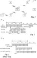
- FIG. 2 illustrates a first timing diagram 200 highlighting a pipeline for scheduling and transmitting of a burst transmission in a communications system.
- a transmitting device such as a gNB, schedules a channel occupancy time (COT) 205 comprising two downlink (DL) transmission time intervals (TTIs) (shown as DL#1 210 and DL#2 212) and two uplink (UL) TTIs (shown as UL#1 214 and UL#2 216).
- a COT is defined as a time period during which a device can have access to a given channel without re-evaluating the availability of that channel.
- a maximum COT (MCOT) is a maximum amount of time a device is allowed to occupy the channel after obtaining access to the channel. In general, a COT is less than or equal to MCOT.
- a transmission prepared for DL#1 210 is scheduled for transmission in slot n+1, and is prepared for transmission in the previous time slot n.
- a slot is a duration of time and is one of a variety of time domain resources of a communications system.
- a slot is 0.5 ms in duration and comprises six or seven orthogonal frequency division multiplexing (OFDM) symbols.
- OFDM orthogonal frequency division multiplexing
- two slots make up a subframe, 10 subframes form a frame, and a TTI is a subframe.
- a slot contains 14 OFDM symbols.
- a TTI can be any combination of slots, mini-slots, etc., that are used for scheduling. Other communications systems have other slot configurations. Other TTIs are similarly prepared for transmission prior to their scheduled transmissions.
- UL#1 214 is specified by information included in DL#1 210
- UL#2 216 is specified by information included in DL#2 212.
- COT 205 comprises four slots. However, a COT, in general, can include an arbitrary number of slots (unless restricted by technical standard or deployment setting).
- the transmitting device discards the transmission that was prepared for DL#1 210.
- the transmission cannot be reused in a later slot because the signals generated for slot n+1 are time dependent. Furthermore, remaining time is not sufficient for generating signals for DL#1 in slot n+1.
- the transmission prepared for DL#1 210 is delayed for a time period because it is rescheduled by a media access control (MAC) layer entity and regenerated by a physical (PHY) layer entity (shown as DL#1* 222).
- MAC media access control
- PHY physical
- a time independent initial block (or initial blocks) is included in a COT.
- the initial block is used for burst identification or slot identification.
- the initial block may also be referred to as an identification signal or identification block.
- the initial block is independent of an absolute time, such as a system time, absolute slot index, absolute mini-slot index, etc.
- an initial block is independent of a slot index, subframe index, or symbol index that is itself, relative to a cell specific synchronization signal. Nevertheless, when multiple initial blocks are transmitted in the time domain within a COT, they are still dependent on their relative slot indices with respect to the reference slot, subframe, or symbol of that COT.
- the inclusion of the time independent initial block in the COT addresses issues, such as the interruption of a COT transmission due to LBT failure and the discarding of transmissions prepared for TTIs, the large packet delay due to HARQ rescheduling, the waste of computational and processing resources, the high hardware requirement associated with processing delays, and the degraded interference whitening performance.
- the initial block includes a predefined signal or sequence to help ensure reliable detection by receiving devices.
- the predefined signal or sequence is referred to as an initial sequence.
- the initial sequence may be defined by a technical standard, operator of the communications system, or agreed upon by the communicating devices through collaboration.
- the transmit DL portions (e.g., DL TTIs) of the COT are scrambled using scrambling sequences that are based on a slot index that is relative to the start of the COT.
- the receive UL portions (e.g., UL TTIs) of the COT are scrambled using scrambling sequences that are based on a slot index that is relative to the start of the COT. The use of scrambling sequences that are based on the slot index that is relative to the start of the COT also eliminates the need to regenerate the signals for the transmit DL portions and the receive UL portions should the COT be rescheduled.
- Figure 4 illustrates a flow diagram of example operations 400 occurring in an access node.
- Operations 400 may be indicative of operations occurring in an access node as the access node participates in communications with a UE.
- the access node is participating in communications (e.g., bursty communications) with the UE.
- the bursty communications includes downlink transmissions only or both downlink and uplink transmissions.
- the communications occurs in licensed or unlicensed spectrum.
- Operations 400 begin with the access node contending for access to a communications channel (block 405).
- the access node may contend for access to the communications channel by measuring energy on the communications channel for a specified amount of time and if the measured energy is below a threshold, the access node determines that the communications channel is idle and obtains access to the communications channel. If the measured energy is above the threshold, the access node determines that the communications channel is not idle and not available for access.
- the access node performs a check to determine if access to the communications channel was obtained (block 407). If access to the communications channel was not obtained, the access node returns to block 405 to continue contending for access to the communications channel. The access node may wait for a period of time before it repeats the contention for access to the communications channel.
- the access node If the access node was able to obtain access to the communications channel, the access node generates an initial block (block 409).
- the initial block is independent of the absolute slot index determined during downlink synchronization. In other words, the initial block is not based on an absolute slot index of a slot where the access node intends to transmit the initial block.
- the initial block includes a predefined signal or a sequence (referred to as an initial sequence) that is known to the UE.
- the initial block may also include downlink control information included in a downlink control field.
- the downlink control information includes configuration information for a following COT.
- the configuration information includes at least the remaining duration of the COT (e.g., a number of slots or mini-slots or symbols), and the composition of the COT (e.g., downlink transmission, uplink transmission, or unknown transmission for each slot or mini-slot of the COT).
- the initial block is generated by the access node prior to or during the access node contending for the communications channel.
- the access node transmits the initial block (block 411).
- the access node transmits downlink transmission portions of COT with scrambling based on a slot index relative to the slot where the initial block was transmitted (block 413). In other words, the downlink transmissions made by the access node are scrambled based on a slot index relative to the start of the COT.
- the access node receives uplink transmissions of COT with scrambling based on a slot index relative to the slot where the initial block was transmitted (block 415). In other words, the uplink transmissions received by the access node are scrambled based on a slot index relative to the start of the COT.
- the access node may continue to transmit downlink bursts within the COT with the relative slot indices relative to the slot where the single initial block was transmitted.
- the access node may continue to transmit downlink bursts within the COT with the relative slot indices relative to the slot wherein the most recent initial block was transmitted.
- the transmission of a plurality of initial blocks allows the access node to change the structure of the COT as well as send indications of the changed COT structure, in the downlink control field, for example.
- FIG. 5 illustrates a flow diagram of operations 500 occurring in a UE.
- Operations 500 may be indicative of operations occurring in a UE as the UE participates in communications with an access node.
- the UE is participating in communications (e.g., bursty communications) with the access node.
- the bursty communications includes downlink transmissions only or both downlink and uplink transmissions.
- the communications occurs in licensed or unlicensed spectrum.
- Operations 500 begin with the UE receiving and detecting an initial block (block 505). Because the initial block includes a predefined signal or a sequence that is known to the UE, the UE is able to readily detect the initial block. In general, the UE attempts to receive and detect the initial block at every possible start point of a COT until the UE detects the initial block. The UE determines a start of the COT (block 507). The UE regards a slot where it was able to detect the initial block as the start of the COT, for example. As an illustrative example, if the initial block is detected in slot #n, then slot #n will be considered as a reference slot and the signals and sequences used in the transmissions and receptions will be relative to the reference slot.
- the transmissions and receptions are scrambled with a sequence generated relative to a slot index relative to the slot where the initial block was detected.
- the UE receives downlink portions of the COT with scrambling based on a slot index relative to the slot where the initial block was detected (block 509).
- the UE transmits uplink portions of the COT with scrambling based on a slot index relative to the slot where the initial block was detected (block 511).
- the UE may contend for access to the communications channel.
- the UE If the UE received the initial block but was not able to successfully decode the control information field therein, the UE still has knowledge of a downlink transmission portion of the COT and can continue to monitor the shared communications channel for an additional initial block with associated control information field. The UE can continue the monitoring until it is able to receive and decode the initial block with associated control information field or until a maximum time (as defined by an MCOT, for example) has elapsed.
- a maximum time as defined by an MCOT, for example
- FIG. 6 illustrates a third timing diagram 600 illustrating a technique for pipelining the scheduling and transmitting of a burst transmission utilizing an initial block to help reduce power consumption and processing complexity in situations with LBT failure.
- Timing diagram 600 displays a COT 605 including two DL TTIs (shown as DL#1 610 and DL#2 612) and two UL TTIs (shown as UL#1 614, and UL#2 616).
- COT 605 also includes an initial block 620 that is transmitted at the beginning or near the beginning of COT 605. As shown in Figure 6 , initial block 620 and DL#1 610 are transmitted in slot n+1625, DL#2 612 is transmitted in slot n+2 630, and so on.
- a UE receiving and detecting initial block 620 regards slot n+1 625 as a reference slot and assigns a relative slot index zero to the slot 625.
- Slot n+2 630 is one slot after the reference slot and therefore is assigned relative slot index one.
- Remaining slots of COT 605 are similarly numbered, all relative to the reference slot. In a situation where a downlink portion starts within a slot duration with a mini-slot, the slot that includes the mini-slot is considered to be the reference slot.
- the initial sequence of the initial block is independent of slot index.
- the content of the downlink control field, as well as the scrambling of the downlink control field and a demodulation reference signal (DMRS) of the downlink control field (if not used as the initial sequence) is dependent on the relative slot index.
- the initial sequence is generated a priori.
- a secondary synchronization signal (SSS) as defined in 3GPP LTE and 3GPP New Radio (NR) is used for the initial sequence.
- the SSS is independent of slot index and can be generated a priori.
- a UE can reuse existing SSS detection hardware and algorithm, which helps simplify implementation.
- sequences that are independent of slot index include SSS, primary synchronization signal (PSS), DMRS defined for a physical broadcast channel (PBCH), PDCCH DMRS, DMRS with a predefined slot index (e.g., slot index zero but other values are possible), short training and long training sequences as specified in IEEE 802.11 technical standards, and so on.
- PSS primary synchronization signal
- DMRS defined for a physical broadcast channel (PBCH)
- PBCH physical broadcast channel
- PDCCH DMRS DMRS with a predefined slot index (e.g., slot index zero but other values are possible)
- short training and long training sequences as specified in IEEE 802.11 technical standards, and so on.
- SSS sequence for an initial sequence offers a variety of benefits, including: reliable detection performance; independence of absolute slot index; sufficient number of unique sequences to differentiate from neighbor cells; will not increase synchronization signal block (SSB) false detection for initial access UEs; and reuses existing detection hardware.
- the design of the control information field allows for independence of slot index and sufficient capacity to accommodate information bits.
- Figure 7 illustrates an example slot structure of a COT 700, highlighting a SSS as an initial sequence.
- the initial block is transmitted in sixth and seventh OFDM symbols 707 after an access node successfully contends for access to a 20 MHz communications channel (shown as occurring during first five OFDM symbols 710 of slot n 705).
- the initial block being transmitted in sixth and seventh OFDM symbols 707 is for illustrative purposes only.
- the duration of the initial block is dependent upon the content of the initial block. Hence, the illustration of the two symbol long initial block should not be construed as being limiting to the scope of the example embodiments.
- the SSS i.e., the initial sequence
- the SSS i.e., the initial sequence
- PRBs physical resource blocks
- Discussion of the initial block being transmitted in sixth and seventh OFDM symbols 707, and the length 127 initial sequence occupying 14 PRBs around the center frequency of the OFDM symbol are for illustrative purposes only; the initial block may be transmitted in a different OFDM symbol, and the initial sequence may be of different length and occupy a different number of PRBs.
- the channel contention may occur prior to slot n 705.
- the downlink control field carries the configuration of COT 705 and may be multiplexed with the initial sequence in a frequency division multiplexed (FDM) manner or a time division multiplexed (TDM) manner (such as PRBs 720 and 722).
- a DMRS defined for a PBCH in 3GPP TS 38.211 may be used in each PRB of the control information field.
- a DMRS is carried in a tone, such as subcarrier 724.
- a DMRS defined for a PDCCH may be used in each PRB of the control information field with the slot index set to a predefined value, e.g., zero.
- PRBs 720 and 721 may be used to carry the control information field of the initial block (e.g., PRBs 720 and 721).
- PRBs 720 and 7231 Within each PRB, such as PRB 730, three subcarriers (e.g., subcarrier 724) are used for DMRS.
- the initial blocks may also have additional OFDM symbols for the control information field (e.g., PRB 722). If other subcarrier spacings or bandwidths are adopted, the number of PRBs used by the initial sequence and control information fields may be different from what is shown in Figure 7 .
- the initial sequence (SSS in PRBs 715) is located at the center of the communications channel by default.
- the access node can also configure the position of the initial sequence in system information, e.g., a PBCH, remaining system information (RMSI), or other system information (OSI), or through UE specific radio resource control (RRC) signaling.
- system information e.g., a PBCH, remaining system information (RMSI), or other system information (OSI), or through UE specific radio resource control (RRC) signaling.
- RRC radio resource control
- other parameters of the initial block may be configured, including: a number of OFDM symbols in the time domain, a number of physical resource blocks (PRBs) in the frequency domain, sub-carrier spacing, and so on, for example.
- the configuration of the initial block may be included with the configuration of bandwidth parts (BWPs).
- the initial block also includes a parameter for a relative slot index of a current slot.
- the information, along with other downlink control information, may be encoded together as a single physical layer control channel (such as a PBCH) or encoded as an individual DCI with the resource mapping of a PDCCH in a common search space.
- a physical layer control channel such as a PBCH
- a wideband control resource set is configured at the first or several slots or mini-slots of a COT.
- the DMRS of each PRB within the CORESET are configured in a similar manner as the DMRS of PBCH or DMRS of PDCCH with predefined slot index from a resource mapping and scrambling perspective, as defined in 3GPP TS 38.211, which are independent of slot index.
- the DMRS sequence in the CORESET of the first slot or mini-slot of the COT serves as the initial sequence.
- Some of the PDCCH candidates in the CORESET may be used to carry the downlink control information, as described previously.
- the remainder of the CORESET in the COT that is not carrying the initial block follows the CORESET configuration for CORESETs as specified in 3GPP NR and uses the PDCCH DMRS.
- the remainder of the CORESET within the COT does not necessarily have to be wideband.
- the CORESET carrying initial block(s) and not carrying initial block may have different configuration.
- the UE will assume that the DMRS of the CORESET appears in each PRB even if some PDCCH candidates in the CORESET are not used.
- a CORESET to carry the initial block offers a variety of benefits, including: saving individual OFDM symbols for initial sequences and the DMRS sequences in the CORESET be shared with PDCCH search spaces for data channel scheduling; the initial block is independent of slot index; a PDCCH detection procedure is used (i.e., no specific initial block detection procedure is needed); a sufficient number of sequences are available to differentiate from neighbor cells; and does not increase SSB false detection for initial access UEs.
- the CORESET does not include a SSS to be used as an initial sequence.
- the DMRS sequence is used as an initial sequence.
- the remainder of the PRBs in the signal may be used to convey control information, in accordance with the PBCH structure.
- the initial sequence and the control information may be coded together.
- the initial sequence of the initial block is a separate sequence that is independent of slot index, such as SSS, PSS, short training and long training sequences as specified in IEEE 802.11 technical standards, and so on.
- the initial sequence of the initial block is a DMRS, such as a PBCH DMRS, a PDCCH DMRS, a DMRS with a predefined slot index (e.g., slot index zero but other values are possible), and so on.
- the downlink control field follows the structure of a PDCCH. In an embodiment, the downlink control field follows the structure of a PBCH.
- Figure 8 illustrates an example slot structure of a COT 800, highlighting a CORESET used to carry an initial sequence.
- PBCH DMRS such as PBCH DMRS 807
- PRBs (such as PRBs 820 and 822) are used to carry downlink control information for COT 800.
- a CORESET carried in OFDM symbol 830 of slot n+1 835 may be a regular CORESET conforming to PDCCH DMRS mapping rules.
- a CORESET carrying the initial blocks, such as CORESET 810 may be configured by system information, which may be signaled by PBCH, RMSI, OSI, or RRC signaling.
- the configuration of the CORESET carrying the initial blocks may also be signaled along with BWP configuration.
- the UE Prior to a UE detecting a PDCCH with the assumption of a regular CORESET configuration, the UE may assume a CORESET configuration that includes the CORESET carrying an initial block.
- one initial block of a plurality of initial blocks is transmitted on each subband where a LBT process succeeds.
- an access node is configured for wideband transmission, such as through carrier aggregation (CA) or single wideband component carrier (CC)
- CA carrier aggregation
- CC single wideband component carrier
- a UE may obtain the actual transmission bandwidth of the COT by detecting the existence of initial blocks on each subband. If CA is used, the initial block on each CC will be different because each CC has its own cell identifier. If single wideband CC is used, the initial block is duplicated on each subband assuming the same cell identifier is used.
- the reliability of detection of the initial block is increased by transmitting multiple initial blocks or sequences in the frequency domain, the time domain, or both the frequency and time domains.
- the simplified initial block reduces communications overhead in a situation when multiple initial blocks are transmitted.
- FIG 9A illustrates a wideband COT 900 in a deployment utilizing CA.
- COT 900 comprises four CCs, such as CC 905 and CC 907. Each of the four CCs carries a different initial block, such as initial blocks 910 and 912, because each CC has its own cell identifier.
- Figure 9B illustrates a wideband COT 930 in a deployment utilizing a single wideband CC.
- COT 930 comprises four bonded channels. Each of the four channels carries a copy of an initial block, such as initial blocks 935 and 937.
- each channel in a subset of the plurality of bonded channels will carry a copy of the initial block. In other words, some of the bonded channels will carry a copy of the initial block.
- the UE receiving the wideband COT when the UE detects the initial block on any one of the channels, the UE will be able to obtain full knowledge of the wideband COT. In this deployment, the UE is not required to detect the initial block on each channel, therefore, the computational requirements on the UE is reduced. Reduced computational requirements may enable the use of a lower complexity UE.
- FIG. 9C illustrates a wideband COT 960 in a deployment utilizing a single wideband CC, highlighting a failed LBT process in one of the channels.
- COT 960 comprises four bonded channels, however, channel 965 is determined to be unavailable during a LBT process and is not used in COT 960.
- COT 960 comprises the three bonded channels that are available.
- Each of the three channels carries a copy of an initial block, such as initial blocks 970 and 972. Because channel 965 is unavailable, the initial block is not transmitted in resources 974 of channel 965.
- the access node may transmit an initial block from a plurality of initial blocks at the beginning of several or all slots or mini-slots.
- the presence of the plurality of initial blocks provides additional reliability if some UEs miss early initial blocks or are not configured to monitor initial blocks at every possible start point.
- the relative slot index and the COT structure in the initial blocks may be updated by the access node according to the slot where the initial blocks are transmitted. If a UE detects multiple initial blocks, the UE will update based on a most recently received version of the initial block.
- the simplified initial blocks include only a portion of the downlink control information included in the full initial blocks, for example.
- the simplified initial blocks include only a relative slot index of the current slot in the control information field, along with the initial sequence.
- a simplified version of the initial block includes only the initial sequence.
- the access node may transmit the simplified initial block in one or more slots after the one or more slots carrying the full initial blocks within the COT.
- the initial sequence in the full initial block and the simplified initial block may be different in order to allow the UE to recognize the different initial blocks.
- the different initial block formats may also be distinguished by different scrambling sequences or radio network temporary identifier (RNTI) on the cyclic redundancy check (CRC) of the downlink control information following the initial sequence.
- RNTI radio network temporary identifier
- CRC cyclic redundancy check
- FIG. 10 illustrates an example slot structure of a COT 1000, highlighting full and simplified initial blocks.
- COT 1000 comprises six slots, slots n through n+5.
- full initial blocks 1020 are transmitted in slots n 1005 and n+1 1007
- simplified initial blocks 1025 are transmitted in slots n+2 1009, n+3 1011, n+4 1013, and n+5 1015.
- the simplified initial blocks may include a reduced version of the downlink control information included in the full initial blocks.
- COT 1000 is shown to include two instances of the full initial blocks and four instances of the simplified initial blocks, there are no limitations on the number of full initial blocks and simplified initial blocks in any particular COT.
- every slot of COT 1000 is shown to include an initial block.
- every slot in a COT include an initial block, either full initial block or simplified initial block.
- a first subset of the CCs may convey full initial blocks and a second subset of the CCs may convey simplified initial blocks.
- the CCs of the first subset and the second subset can change for different slots or mini-slots.
- FIG. 11 illustrates an example slot structure of a COT 1100, highlighting multiple initial sequences in an initial block.
- OFDM symbol 1110 of slot n 1105 of COT 1100 conveys an initial block.
- the initial block includes at least two instances of an initial sequence, SSS 1120 and 1122.
- Each instance of the initial sequence may have smaller bandwidth than a single initial sequence.
- the initial sequence instances may be spread apart within the frequency domain to increase frequency diversity, for example.
- the initial sequence of the COT is independent of the absolute slot index, while any remaining sequences of the COT is based on a relative slot index, relative to the start of the COT.
- the remaining sequences e.g., the DMRS of the PDCCH, PDSCH, or CSI-RS, are based on the relative slot index of the slot or mini-slot where the initial sequence is transmitted.
- the relative slot index is relative to the start of the COT.
- the signals are independent of the absolute index obtained from downlink synchronization.
- the generated signals may be buffered when a LBT failure occurs and reused at a later slot, instead of being discarded. Hence, computation resources of the transmitting device are saved.
- the initial number (or seed) used for initializing the pseudo-random number generator of the scrambling sequences are expressible as:
- the access node descrambles the DMRS of a physical uplink control channel (PUCCH) format 2 and DMRS or PTRS of PUSCH in a target slot or mini-slot using its relative slot index.
- PUCCH physical uplink control channel
- PTRS PTRS of PUSCH
- group and sequence hopping for PUCCH format 0, 1, 3, and 4 are as follows:
- SR spatial reuse
- different relative slot indices are used for SR transmissions to improve inter-cell interference whitening at UEs in different cells of the SR access nodes.
- the access nodes of the same operator network jointly access the unlicensed channel. Therefore, the transmissions of the SR access nodes overlap in the unlicensed time-frequency resources with either aligned or unaligned transmission start.
- the overlap of the unlicensed time-frequency resources can be realized by alignment of the transmission start point or by delayed joint channel access.
- the network or access node may need to generate the concurrent SR transmissions using different relative slot indices to improve the inter-cell interference whitening at the UEs in the different cells of the SR access nodes.
- NR-U 3GPP NR Unlicensed
- networks have the flexibility to change relative slot indices used for the generation of the downlink only or shared COT with respect to the UE side configuration by signaling a slot index offset so that the UE can apply the offset to the relative slot index and thus properly descramble or decode respective down link bursts, or generate uplink bursts.
- scrambling or hopping performance similar to that of 3GPP NR frequency reuse may be achieved in concurrent slots across inter-cell SR access nodes, which are likely to be in close proximity to each other.
- the access node or network may be allowed to generate intra-cell SR transmissions of unaligned start points using the same relative slot indices over concurrent slots so that the same scrambling or hopping sequences are used in the concurrent slots of the intra-cell SR transmissions.
- Figure 12A illustrates example COTs transmitted by SR access nodes, highlighting the use of different relative slot indices to improve inter-cell interference whitening in a synchronous system.
- a first COT 1205 is transmitted by a first SR access node and a second COT 1207 is transmitted by a second SR access node.
- First COT 1205 and second COT 1207 are transmitted concurrently in the same slots starting from the same reference slot. If relative slot indices are used, same relative slot indices are going to be used across concurrent slots of the two COTs, and thus inter-cell interference whitening would be degraded.
- first SR access node sets the reference slot index to zero for transmissions of the first SR access node, and the reference slot index for transmissions of the second SR access node is set to m, where m is not equal to 0.
- the downlink control field of an initial block may include a Slot Index Offset that the UEs apply to the relative slot indices for descrambling and decoding. If after applying the Slot Index Offset to the relative slot indices, any of the new relative slot indices exceed the maximum number of slots in a radio frame, a cyclic shift (or a modulo operation) may be applied to the new relative slot indices. As shown in Figure 12 , UEs receiving the COTs apply respective relative slot indices for proper descrambling and decoding. As an alternative to the Slot Index Offset, the relative slot index may also be carried in the downlink control field. If the relative slot index is not equal to zero, then the Slot Index Offset is included in the downlink control field, for example.
- the UE may also assume that Slot#6 is the fourth slot of COT 1257 wherein the first three slots were missed including the reference slot with slot index 3. Indicating a slot index offset equal to 5 confirms the latter case.
- Figure 13 illustrates example COTs transmitted by SR access nodes, highlighting the use of different slot index offsets to facilitate intra-cell SR transmissions to the same UE with unaligned transmission start.
- SR transmissions are not aligned at the start point, they do not share the same reference slot. Therefore, different relative slot indices would be normally used to generate the concurrent transmissions across the different cells of the SR access nodes.
- a UE may be served by more than one access node utilizing SR in the unlicensed channel.
- a first COT 1305 is transmitted by a first SR access node (AN1) and a second COT 1307 is transmitted by a second SR access node (AN2).
- the first access node and the second access node are of a single cell and are serving a UE.
- the access nodes in such case may need to generate concurrent SR transmissions using the same relative slot indices so that the same scrambling or hopping sequences are used in the concurrent slots of the COTs.
- the slot index offset for second COT 1307 is one (instead of zero) to match the relative slot index of the same slot of first COT 1305.
- the network can use the downlink control field of the initial block to include a Slot Index Offset that the UEs apply to the relative slot indices for descrambling and decoding of intra-cell SR transmissions.
- the downlink control field of the initial blocks of second SR access node includes a Slot Index Offset value of one.
- control overhead savings may be achieved if the access node does not need to dynamically signal the Slot Index Offsets to the respective UEs. Instead, the UEs can be pre-configured with the respective Slot Index Offsets (in a semi-static manner) for example, using higher-layer signaling, such as radio resource control (RRC) signaling.
- RRC radio resource control
- the initial blocks may include information of the MCOT so that the transmission can end at the end point of the shared MCOT.
- initial blocks in order to enable inter-cell detection of COTs, initial blocks also include a PSS.
- PSS a PSS
- the initial blocks without the PSS may enable only intra-cell detection (i.e., detection by UEs or access nodes of the same cell).
- the inclusion of the PSS in the initial blocks allows UEs or access nodes of other cells to attain full time synchronization.
- the design of the initial block should be unified, at least within the same network.
- SSB synchronization signal block
- PSS allows for inter-cell time synchronization, allows NR-U to benefit from improved intra- or inter-operator coexistence and spatial reuse, and avoids performance degradation and failure or latency of initial access by avoiding false detection of the initial blocks as SSBs by UEs performing initial access.
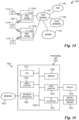
- Figure 14 illustrates an example communication system 1400.
- the system 1400 enables multiple wireless or wired users to transmit and receive data and other content.
- the system 1400 may implement one or more channel access methods, such as code division multiple access (CDMA), time division multiple access (TDMA), frequency division multiple access (FDMA), orthogonal FDMA (OFDMA), single-carrier FDMA (SC-FDMA), or non-orthogonal multiple access (NoMA).
- CDMA code division multiple access
- TDMA time division multiple access
- FDMA frequency division multiple access
- OFDMA orthogonal FDMA
- SC-FDMA single-carrier FDMA
- NoMA non-orthogonal multiple access
- the communication system 1400 includes electronic devices (ED) 1410a-1410c, radio access networks (RANs) 1420a-1420b, a core network 1430, a public switched telephone network (PSTN) 1440, the Internet 1450, and other networks 1460.
- ED electronic devices
- RANs radio access networks
- PSTN public switched telephone network
- the EDs 1410a-1410c are configured to operate or communicate in the system 1400.
- the EDs 1410a-1410c are configured to transmit or receive via wireless or wired communication channels.
- Each ED 1410a-1410c represents any suitable end user device and may include such devices (or may be referred to) as a user equipment or device (UE), wireless transmit or receive unit (WTRU), mobile station, fixed or mobile subscriber unit, cellular telephone, personal digital assistant (PDA), smartphone, laptop, computer, touchpad computer or device, wireless sensor, or consumer electronics device.
- UE user equipment or device
- WTRU wireless transmit or receive unit
- PDA personal digital assistant
- smartphone laptop, computer, touchpad computer or device, wireless sensor, or consumer electronics device.
- the RANs 1420a-1420b here include base stations 1470a-1470b, respectively.
- Each base station 1470a-1470b is configured to wirelessly interface with one or more of the EDs 1410a-1410c to enable access to the core network 1430, the PSTN 1440, the Internet 1450, or the other networks 1460.
- the base stations 1470a-1470b may include (or be) one or more of several well-known devices, such as a base transceiver station (BTS), a Node-B (NodeB), an evolved NodeB (eNodeB), a Next Generation (NG) NodeB (gNB), a Home NodeB, a Home eNodeB, a site controller, an access point (AP), or a wireless router.
- the EDs 1410a-1410c are configured to interface and communicate with the Internet 1450 and may access the core network 1430, the PSTN 1440, or the other networks 1460.
- the base station 1470a forms part of the RAN 1420a, which may include other base stations, elements, or devices.
- the base station 1470b forms part of the RAN 1420b, which may include other base stations, elements, or devices.
- Each base station 1470a-1470b operates to transmit or receive wireless signals within a particular geographic region or area, sometimes referred to as a "cell.”
- MIMO multiple-input multiple-output
- the base stations 1470a-1470b communicate with one or more of the EDs 1410a-1410c over one or more air interfaces 1490 using wireless communication links.
- the air interfaces 1490 may utilize any suitable radio access technology.
- the system 1400 may use multiple channel access functionality, including such schemes as described above.
- the base stations and EDs implement 5G New Radio (NR), LTE, LTE-A, or LTE-B.
- NR 5G New Radio
- LTE Long Term Evolution
- LTE-A Long Term Evolution
- LTE-B Long Term Evolution-B
- the RANs 1420a-1420b are in communication with the core network 1430 to provide the EDs 1410a-1410c with voice, data, application, Voice over Internet Protocol (VoIP), or other services. Understandably, the RANs 1420a-1420b or the core network 1430 may be in direct or indirect communication with one or more other RANs (not shown).
- the core network 1430 may also serve as a gateway access for other networks (such as the PSTN 1440, the Internet 1450, and the other networks 1460).
- some or all of the EDs 1410a-1410c may include functionality for communicating with different wireless networks over different wireless links using different wireless technologies or protocols. Instead of wireless communication (or in addition thereto), the EDs may communicate via wired communication channels to a service provider or switch (not shown), and to the Internet 1450.
- Figure 14 illustrates one example of a communication system
- the communication system 1400 could include any number of EDs, base stations, networks, or other components in any suitable configuration.
- Figures 15A and 15B illustrate example devices that may implement the methods and teachings according to this disclosure.
- Figure 15A illustrates an example ED 1510
- Figure 15B illustrates an example base station 1570. These components could be used in the system 1400 or in any other suitable system.
- the ED 1510 includes at least one processing unit 1500.
- the processing unit 1500 implements various processing operations of the ED 1510.
- the processing unit 1500 could perform signal coding, data processing, power control, input/output processing, or any other functionality enabling the ED 1510 to operate in the system 1400.
- the processing unit 1500 also supports the methods and teachings described in more detail above.
- Each processing unit 1500 includes any suitable processing or computing device configured to perform one or more operations.
- Each processing unit 1500 could, for example, include a microprocessor, microcontroller, digital signal processor, field programmable gate array, or application specific integrated circuit.
- the ED 1510 also includes at least one transceiver 1502.
- the transceiver 1502 is configured to modulate data or other content for transmission by at least one antenna or NIC (Network Interface Controller) 1504.
- the transceiver 1502 is also configured to demodulate data or other content received by the at least one antenna 1504.
- Each transceiver 1502 includes any suitable structure for generating signals for wireless or wired transmission or processing signals received wirelessly or by wire.
- Each antenna 1504 includes any suitable structure for transmitting or receiving wireless or wired signals.
- One or multiple transceivers 1502 could be used in the ED 1510, and one or multiple antennas 1504 could be used in the ED 1510.
- a transceiver 1502 could also be implemented using at least one transmitter and at least one separate receiver.
- the ED 1510 further includes one or more input/output devices 1506 or interfaces (such as a wired interface to the Internet 1450).
- the input/output devices 1506 facilitate interaction with a user or other devices (network communications) in the network.
- Each input/output device 1506 includes any suitable structure for providing information to or receiving information from a user, such as a speaker, microphone, keypad, keyboard, display, or touch screen, including network interface communications.
- the ED 1510 includes at least one memory 1508.
- the memory 1508 stores instructions and data used, generated, or collected by the ED 1510.
- the memory 1508 could store software or firmware instructions executed by the processing unit(s) 1500 and data used to reduce or eliminate interference in incoming signals.
- Each memory 1508 includes any suitable volatile or non-volatile storage and retrieval device(s). Any suitable type of memory may be used, such as random access memory (RAM), read only memory (ROM), hard disk, optical disc, subscriber identity module (SIM) card, memory stick, secure digital (SD) memory card, and the like.
- the base station 1570 includes at least one processing unit 1550, at least one transceiver 1552, which includes functionality for a transmitter and a receiver, one or more antennas 1556, at least one memory 1558, and one or more input/output devices or interfaces 1566.
- a scheduler which would be understood by one skilled in the art, is coupled to the processing unit 1550. The scheduler could be included within or operated separately from the base station 1570.
- the processing unit 1550 implements various processing operations of the base station 1570, such as signal coding, data processing, power control, input/output processing, or any other functionality.
- the processing unit 1550 can also support the methods and teachings described in more detail above.
- Each processing unit 1550 includes any suitable processing or computing device configured to perform one or more operations.
- Each processing unit 1550 could, for example, include a microprocessor, microcontroller, digital signal processor, field programmable gate array, or application specific integrated circuit.
- Each transceiver 1552 includes any suitable structure for generating signals for wireless or wired transmission to one or more EDs or other devices. Each transceiver 1552 further includes any suitable structure for processing signals received wirelessly or by wire from one or more EDs or other devices. Although shown combined as a transceiver 1552, a transmitter and a receiver could be separate components. Each antenna 1556 includes any suitable structure for transmitting or receiving wireless or wired signals. Although a common antenna 1556 is shown here as being coupled to the transceiver 1552, one or more antennas 1556 could be coupled to the transceiver(s) 1552, allowing separate antennas 1556 to be coupled to the transmitter and the receiver if equipped as separate components.
- Each memory 1558 includes any suitable volatile or non-volatile storage and retrieval device(s).
- Each input/output device 1566 facilitates interaction with a user or other devices (network communications) in the network.
- Each input/output device 1566 includes any suitable structure for providing information to or receiving/providing information from a user, including network interface communications.
- FIG. 16 is a block diagram of a computing system 1600 that may be used for implementing the devices and methods disclosed herein.
- the computing system can be any entity of UE, access network (AN), mobility management (MM), session management (SM), user plane gateway (UPGW), or access stratum (AS).
- Specific devices may utilize all of the components shown or only a subset of the components, and levels of integration may vary from device to device.
- a device may contain multiple instances of a component, such as multiple processing units, processors, memories, transmitters, receivers, etc.
- the computing system 1600 includes a processing unit 1602.
- the processing unit includes a central processing unit (CPU) 1614, memory 1608, and may further include a mass storage device 1604, a video adapter 1610, and an I/O interface 1612 connected to a bus 1620.
- the bus 1620 may be one or more of any type of several bus architectures including a memory bus or memory controller, a peripheral bus, or a video bus.
- the CPU 1614 may comprise any type of electronic data processor.
- the memory 1608 may comprise any type of non-transitory system memory such as static random access memory (SRAM), dynamic random access memory (DRAM), synchronous DRAM (SDRAM), read-only memory (ROM), or a combination thereof.
- SRAM static random access memory
- DRAM dynamic random access memory
- SDRAM synchronous DRAM
- ROM read-only memory
- the memory 1608 may include ROM for use at boot-up, and DRAM for program and data storage for use while executing programs.
- the mass storage 1604 may comprise any type of non-transitory storage device configured to store data, programs, and other information and to make the data, programs, and other information accessible via the bus 1620.
- the mass storage 1604 may comprise, for example, one or more of a solid state drive, hard disk drive, a magnetic disk drive, or an optical disk drive.
- the video adapter 1610 and the I/O interface 1612 provide interfaces to couple external input and output devices to the processing unit 1602.
- input and output devices include a display 1618 coupled to the video adapter 1610 and a mouse, keyboard, or printer 1616 coupled to the I/O interface 1612.
- Other devices may be coupled to the processing unit 1602, and additional or fewer interface cards may be utilized.
- a serial interface such as Universal Serial Bus (USB) (not shown) may be used to provide an interface for an external device.
- USB Universal Serial Bus
- the processing unit 1602 also includes one or more network interfaces 1606, which may comprise wired links, such as an Ethernet cable, or wireless links to access nodes or different networks.
- the network interfaces 1606 allow the processing unit 1602 to communicate with remote units via the networks.
- the network interfaces 1606 may provide wireless communication via one or more transmitters/transmit antennas and one or more receivers/receive antennas.
- the processing unit 1602 is coupled to a local-area network 1622 or a wide-area network for data processing and communications with remote devices, such as other processing units, the Internet, or remote storage facilities.
- Figure 17 illustrates a flow diagram of example operations 1700 occurring in an access node performing a transmission that involves a LBT failure.
- Operations 1700 may be indicative of operations occurring in an access node as the access node performs a transmission that involves a LBT failure.
- Operations 1700 begin with the access node generating an initial block (block 1705).
- the initial block includes a time-independent initial sequence.
- the access node performs a LBT procedure and determines that the shared communications channel is unavailable during a first slot (block 1707).
- the access node waits and tries the LBT procedure again during a second slot and determines that the shared communications channel is available during a second slot and transmits the initial block (block 1709).
- the access node did not have to regenerate the initial block due to the initial block including the time-independent initial sequence.
- a signal may be transmitted by a transmitting unit or a transmitting module.
- a signal may be received by a receiving unit or a receiving module.
- a signal may be processed by a processing unit or a processing module.
- Other steps may be performed by a generating unit or module, or an adjusting unit or module.
- the respective units or modules may be hardware, software, or a combination thereof.
- one or more of the units or modules may be an integrated circuit, such as field programmable gate arrays (FPGAs) or application-specific integrated circuits (ASICs).
- FPGAs field programmable gate arrays
- ASICs application-specific integrated circuits
Landscapes
- Engineering & Computer Science (AREA)
- Signal Processing (AREA)
- Computer Networks & Wireless Communication (AREA)
- Physics & Mathematics (AREA)
- Health & Medical Sciences (AREA)
- General Health & Medical Sciences (AREA)
- Spectroscopy & Molecular Physics (AREA)
- Mobile Radio Communication Systems (AREA)
Claims (15)
- Computerimplementiertes Verfahren (400) zum Betreiben eines Zugangsknotens, wobei das Verfahren Folgendes umfasst:Erzeugen (409) eines Anfangsblocks und eines zeitabhängigen Signals durch den Zugangsknoten zur Übertragung in einer Kanalbelegungszeit, COT, eines gemeinsam genutzten Kommunikationskanals, wobei der Anfangsblock eine zeitunabhängige Anfangssequenz umfasst, die die Übertragung des Anfangsblocks über jeden beliebigen Slot in der COT ermöglicht, wobei das zeitabhängige Signal nach dem Anfangsblock übertragen wird; undSenden (411) des Anfangsblocks und des zeitabhängigen Signals durch den Zugriffsknoten in einem ersten Slot der COT.
- Verfahren nach Anspruch 1, wobei die zeitunabhängige Anfangssequenz ein Demodulationsreferenzsignal DMRS für Steuerinformationen umfasst.
- Verfahren nach Anspruch 2, wobei das DMRS für Steuerinformationen über einen physischen Broadcast-Kanal, PBCH, oder einen physischen Downlink-Steuerkanal, PDCCH, übertragen wird, der die Struktur eines Steuerressourcensatzes, CORESET, aufweist.
- Verfahren nach Anspruch 3, wobei das DMRS für Steuerinformationen ein DMRS für einen oder mehrere physische Downlink-Steuerkanäle, PDCCHs, im CORESET zu Beginn der COT ist.
- Verfahren nach Anspruch 4, wobei es sich bei den einem oder mehreren PDCCHs um gruppengemeinsame GC-PDCCHs in einem gemeinsamen Suchraum zu Beginn der COT handelt.
- Verfahren gemäß Anspruch 5, wobei der GC-PDCCH eine COT-Strukturanzeige in einem oder mehreren der folgenden Bereiche trägt: einem Zeitbereich und einem Frequenzbereich.
- Verfahren nach einem der Ansprüche 1 bis 6, wobei der Anfangsblock zu Beginn jedes einer Vielzahl von Downlink, DL, - Bursts innerhalb der COT übertragen wird.
- Verfahren nach einem der Ansprüche 1 bis 7, wobei der Anfangsblock den Slot identifiziert, innerhalb dessen er als Referenz-Slot übertragen wird.
- Verfahren nach Anspruch 8, wobei das zeitabhängige Signal relativ zu einer Zeit des Referenz-Slots zeitabhängig ist.
- Verfahren nach einem der Ansprüche 1 bis 9, wobei der Anfangsblock außerdem Steuerinformationen zum Konfigurieren der COT umfasst.
- Verfahren nach Anspruch 10, wobei die Steuerinformationen mindestens einen Indikator für eine Dauer der COT oder einen Indikator für eine Zusammensetzung der COT umfassen.
- Verfahren nach Anspruch 11, wobei der Indikator der Zusammensetzung der COT einen Übertragungstyp für jeden Slot der COT umfasst.
- Verfahren nach Anspruch 10, wobei ein relativer Slot-Index des Slots, in dem sich der Anfangsblock befindet, in einem Steuerinformationsfeld des Anfangsblocks enthalten ist.
- Zugangsknoten (1590) zur Verwendung in einem Drahtlosnetzwerk, umfassend:einen Sender (1552);einen Prozessor (1550); undein nicht flüchtiges computerlesbares Medium (1558), das Anweisungen enthält, die, wenn sie vom Prozessor ausgeführt werden, bewirken, dass der Zugangsknoten das Verfahren nach Anspruch 1 ausführt.
- Zugangsknoten (1590) gemäß Anspruch 14, wobei das nicht flüchtige computerlesbare Medium (1558) außerdem Anweisungen enthält, die, wenn sie vom Prozessor ausgeführt werden, bewirken, dass der Zugangsknoten das Verfahren gemäß einem der Ansprüche 2 bis 13 ausführt.
Applications Claiming Priority (3)
| Application Number | Priority Date | Filing Date | Title |
|---|---|---|---|
| US201862716869P | 2018-08-09 | 2018-08-09 | |
| US16/534,931 US11102817B2 (en) | 2018-08-09 | 2019-08-07 | System and method for supporting bursty communications in wireless communications systems |
| PCT/CN2019/099742 WO2020030036A1 (en) | 2018-08-09 | 2019-08-08 | System and method for supporting bursty communications in wireless communications systems |
Publications (3)
| Publication Number | Publication Date |
|---|---|
| EP3831114A1 EP3831114A1 (de) | 2021-06-09 |
| EP3831114A4 EP3831114A4 (de) | 2021-08-18 |
| EP3831114B1 true EP3831114B1 (de) | 2025-04-23 |
Family
ID=69407170
Family Applications (1)
| Application Number | Title | Priority Date | Filing Date |
|---|---|---|---|
| EP19846273.1A Active EP3831114B1 (de) | 2018-08-09 | 2019-08-08 | System und verfahren zur unterstützung von burst-kommunikationen in drahtloskommunikationssystemen |
Country Status (4)
| Country | Link |
|---|---|
| US (1) | US11102817B2 (de) |
| EP (1) | EP3831114B1 (de) |
| CN (1) | CN112534854B (de) |
| WO (1) | WO2020030036A1 (de) |
Families Citing this family (15)
| Publication number | Priority date | Publication date | Assignee | Title |
|---|---|---|---|---|
| EP4224967A1 (de) | 2017-03-24 | 2023-08-09 | Telefonaktiebolaget LM Ericsson (publ) | Mehrere start- und endpositionen für geplante oder autonome uplink-übertragung in einem unlizenzierten spektrum |
| EP3616450B1 (de) * | 2017-04-28 | 2022-01-26 | Telefonaktiebolaget LM Ericsson (publ) | Mehrfachstartpositionen für uplink-übertragung auf unlizenzierten spektren |
| CN110166189A (zh) * | 2018-02-11 | 2019-08-23 | 索尼公司 | 电子设备、无线通信方法和计算机可读存储介质 |
| CN110932829B (zh) | 2018-09-20 | 2022-04-01 | 维沃移动通信有限公司 | 非授权频段的传输时间指示方法、网络设备和终端 |
| CN111263450B (zh) * | 2019-01-11 | 2022-09-30 | 维沃移动通信有限公司 | Pdcch监测方法、装置、终端、基站和存储介质 |
| US11516842B2 (en) * | 2019-03-27 | 2022-11-29 | Qualcomm Incorporated | Channel occupancy time (COT) structure indication |
| US11291025B2 (en) * | 2019-07-16 | 2022-03-29 | Qualcomm Incorporated | Remaining channel occupancy time indications |
| US11129179B2 (en) * | 2019-07-25 | 2021-09-21 | Landis+Gyr Innovations, Inc. | Initiating or postponing radio transmissions in compliance with dwell time limitations |
| US11849481B2 (en) * | 2019-08-08 | 2023-12-19 | Qualcomm Incorporated | Techniques for configuring multiple-SCS and multi-beam direction communications |
| US12057980B2 (en) * | 2019-10-31 | 2024-08-06 | Qualcomm Incorporated | Cyclic prefix distribution |
| US11563533B2 (en) * | 2019-11-25 | 2023-01-24 | Qualcomm Incorporated | Uplink frequency hopping in unlicensed frequency band |
| PH12022551824A1 (en) | 2020-02-28 | 2024-02-12 | Qualcomm Inc | Listen before talk techniques for wireless communications systems |
| CN114009120B (zh) * | 2020-05-28 | 2025-06-24 | 北京小米移动软件有限公司 | 信息传输方法、装置及通信设备 |
| WO2021253435A1 (en) * | 2020-06-19 | 2021-12-23 | Lenovo (Beijing) Limited | Method and apparatus for sequence determination in wireless transmission |
| US11729637B2 (en) * | 2020-06-30 | 2023-08-15 | Mediatek Inc. | Enhancement to expedite secondary cell (SCell) or primary SCell (PSCell) addition or activation |
Family Cites Families (10)
| Publication number | Priority date | Publication date | Assignee | Title |
|---|---|---|---|---|
| CN110035551B (zh) | 2014-11-05 | 2022-05-31 | 上海朗帛通信技术有限公司 | 一种laa调度方法和装置 |
| US10277366B2 (en) | 2015-01-30 | 2019-04-30 | Electronics And Telecommunications Research Institute | Method and apparatus for transmitting signal using unlicensed band in cellular system |
| US20160302230A1 (en) * | 2015-04-10 | 2016-10-13 | Samsung Electronics Co., Ltd | Methods and apparatus for rrm measurement on unlicensed spectrum |
| US10314063B2 (en) | 2015-05-12 | 2019-06-04 | Electronics And Telecommunications Research Institute | Method and apparatus for transmitting adaptive partial subframe in unlicensed frequency band, method and apparatus for identifying a frame structure, and method and apparatus for transmitting signal |
| US10455433B2 (en) * | 2015-06-16 | 2019-10-22 | Lg Electronics Inc. | Method and apparatus for transmitting or receiving downlink signal in unlicensed band of wireless communication system |
| CN107889114B (zh) | 2016-09-30 | 2023-11-17 | 华为技术有限公司 | 一种非授权频谱信道占用的方法及设备 |
| KR102366007B1 (ko) * | 2017-07-14 | 2022-02-22 | 삼성전자 주식회사 | 무선 통신 시스템에서 하향링크 제어 채널 수신 시간 설정 방법 및 장치 |
| EP3738378B1 (de) * | 2018-01-12 | 2023-07-19 | Nokia Technologies Oy | Uplink-kanalplanung zur erhaltung der kanalbelegung für unlizenziertes drahtloses spektrum |
| US20190349815A1 (en) * | 2018-05-11 | 2019-11-14 | Nokia Technologies Oy | Uplink bandwidth part switching |
| CN110784926B (zh) * | 2018-07-31 | 2023-06-20 | 华硕电脑股份有限公司 | 无线通信系统中指示未授权小区的时隙格式的方法和设备 |
-
2019
- 2019-08-07 US US16/534,931 patent/US11102817B2/en active Active
- 2019-08-08 CN CN201980052053.9A patent/CN112534854B/zh active Active
- 2019-08-08 WO PCT/CN2019/099742 patent/WO2020030036A1/en not_active Ceased
- 2019-08-08 EP EP19846273.1A patent/EP3831114B1/de active Active
Also Published As
| Publication number | Publication date |
|---|---|
| EP3831114A1 (de) | 2021-06-09 |
| CN112534854B (zh) | 2024-04-09 |
| CN112534854A (zh) | 2021-03-19 |
| US20200053782A1 (en) | 2020-02-13 |
| EP3831114A4 (de) | 2021-08-18 |
| WO2020030036A1 (en) | 2020-02-13 |
| US11102817B2 (en) | 2021-08-24 |
Similar Documents
| Publication | Publication Date | Title |
|---|---|---|
| US11102817B2 (en) | System and method for supporting bursty communications in wireless communications systems | |
| US20230389070A1 (en) | Category-2 listen-before-talk (lbt) options for new radio-unlicensed (nr-u) | |
| CN110784926B (zh) | 无线通信系统中指示未授权小区的时隙格式的方法和设备 | |
| KR102249567B1 (ko) | 무선 통신 시스템에 있어서 비면허 스펙트럼 내의 셀에 대한 슬롯 포맷 지시 적용 방법 및 장치 | |
| US11304229B2 (en) | Constraints on no listen-before-talk (LBT) transmission during uplink/downlink (UL/DL) switches | |
| CN108886807B (zh) | 发送上行信息的方法和装置及接收上行信息的方法和装置 | |
| US8675605B2 (en) | Frequency hopping in license-exempt/shared bands | |
| US20260059443A1 (en) | Method and apparatus for power saving in sidelink communication | |
| JP6434043B2 (ja) | 無線通信システムにおいて信号を送受信する方法及びそのための装置 | |
| CN107926048B (zh) | 共享通信介质上的基于争用的共存 | |
| EP3275269B1 (de) | Uplink-übertragungssteuerung mit bewertung eines freien kanals in einer sekundären trägerkomponente | |
| US12137479B2 (en) | Method and apparatus for coverage enhancement of terminal in communication system | |
| CN112492613B (zh) | 在支持未授权带的无线接入系统中执行cca的方法及其装置 | |
| US20120307869A1 (en) | Frequency Hopping in License-Exempt/Shared Bands | |
| US12127166B2 (en) | Method and apparatus for coordinating and allocating sidelink resource | |
| EP3858059A1 (de) | Lizenzierter zusätzlicher uplink als fallback mit unlizenziertem uplink und downlink | |
| US20160165622A1 (en) | Nested system operation | |
| CN110447287A (zh) | 非授权频谱中的调度或自主上行链路传输的多个起始和结束位置 | |
| JP2018509028A (ja) | 上りリンク信号を送信する方法及び使用者器機、並びに上りリンク信号を受信する方法及び基地局 | |
| WO2012164531A1 (en) | Frequency hopping in license-exempt/shared bands | |
| CN108352958A (zh) | 用于在非授权带中传输信号的方法、装置、和系统 | |
| CN116830499A (zh) | 资源调度的方法和通信设备 | |
| CN118612881A (zh) | 在未授权频带中执行传输的信道接入方法及使用其的设备 | |
| KR20180022221A (ko) | 비면허대역에서 다중 캐리어 채널엑세스 방법, 장치 및 시스템 | |
| KR20180108351A (ko) | 비면허대역 통신을 위한 다양한 dl전송 구조하에서의 데이터/제어채널의 할당 및 수신 방법, 장치 및 시스템 |
Legal Events
| Date | Code | Title | Description |
|---|---|---|---|
| STAA | Information on the status of an ep patent application or granted ep patent |
Free format text: STATUS: THE INTERNATIONAL PUBLICATION HAS BEEN MADE |
|
| PUAI | Public reference made under article 153(3) epc to a published international application that has entered the european phase |
Free format text: ORIGINAL CODE: 0009012 |
|
| STAA | Information on the status of an ep patent application or granted ep patent |
Free format text: STATUS: REQUEST FOR EXAMINATION WAS MADE |
|
| 17P | Request for examination filed |
Effective date: 20210305 |
|
| AK | Designated contracting states |
Kind code of ref document: A1 Designated state(s): AL AT BE BG CH CY CZ DE DK EE ES FI FR GB GR HR HU IE IS IT LI LT LU LV MC MK MT NL NO PL PT RO RS SE SI SK SM TR |
|
| A4 | Supplementary search report drawn up and despatched |
Effective date: 20210716 |
|
| RIC1 | Information provided on ipc code assigned before grant |
Ipc: H04W 16/14 20090101AFI20210712BHEP Ipc: H04W 72/04 20090101ALI20210712BHEP Ipc: H04L 5/00 20060101ALI20210712BHEP Ipc: H04L 27/00 20060101ALI20210712BHEP Ipc: H04W 74/08 20090101ALN20210712BHEP |
|
| DAV | Request for validation of the european patent (deleted) | ||
| DAX | Request for extension of the european patent (deleted) | ||
| STAA | Information on the status of an ep patent application or granted ep patent |
Free format text: STATUS: EXAMINATION IS IN PROGRESS |
|
| 17Q | First examination report despatched |
Effective date: 20230316 |
|
| REG | Reference to a national code |
Ref country code: DE Ref legal event code: R079 Free format text: PREVIOUS MAIN CLASS: H04W0016140000 Ipc: H04L0005000000 Ref country code: DE Ref legal event code: R079 Ref document number: 602019069106 Country of ref document: DE Free format text: PREVIOUS MAIN CLASS: H04W0016140000 Ipc: H04L0005000000 |
|
| GRAP | Despatch of communication of intention to grant a patent |
Free format text: ORIGINAL CODE: EPIDOSNIGR1 |
|
| STAA | Information on the status of an ep patent application or granted ep patent |
Free format text: STATUS: GRANT OF PATENT IS INTENDED |
|
| RIC1 | Information provided on ipc code assigned before grant |
Ipc: H04W 74/08 20090101ALN20241113BHEP Ipc: H04L 27/00 20060101ALI20241113BHEP Ipc: H04L 5/00 20060101AFI20241113BHEP |
|
| INTG | Intention to grant announced |
Effective date: 20241125 |
|
| GRAS | Grant fee paid |
Free format text: ORIGINAL CODE: EPIDOSNIGR3 |
|
| GRAA | (expected) grant |
Free format text: ORIGINAL CODE: 0009210 |
|
| STAA | Information on the status of an ep patent application or granted ep patent |
Free format text: STATUS: THE PATENT HAS BEEN GRANTED |
|
| AK | Designated contracting states |
Kind code of ref document: B1 Designated state(s): AL AT BE BG CH CY CZ DE DK EE ES FI FR GB GR HR HU IE IS IT LI LT LU LV MC MK MT NL NO PL PT RO RS SE SI SK SM TR |
|
| REG | Reference to a national code |
Ref country code: GB Ref legal event code: FG4D |
|
| REG | Reference to a national code |
Ref country code: CH Ref legal event code: EP |
|
| REG | Reference to a national code |
Ref country code: DE Ref legal event code: R096 Ref document number: 602019069106 Country of ref document: DE |
|
| REG | Reference to a national code |
Ref country code: IE Ref legal event code: FG4D |
|
| REG | Reference to a national code |
Ref country code: NL Ref legal event code: MP Effective date: 20250423 |
|
| PG25 | Lapsed in a contracting state [announced via postgrant information from national office to epo] |
Ref country code: NL Free format text: LAPSE BECAUSE OF FAILURE TO SUBMIT A TRANSLATION OF THE DESCRIPTION OR TO PAY THE FEE WITHIN THE PRESCRIBED TIME-LIMIT Effective date: 20250423 |
|
| REG | Reference to a national code |
Ref country code: AT Ref legal event code: MK05 Ref document number: 1788860 Country of ref document: AT Kind code of ref document: T Effective date: 20250423 |
|
| PG25 | Lapsed in a contracting state [announced via postgrant information from national office to epo] |
Ref country code: PT Free format text: LAPSE BECAUSE OF FAILURE TO SUBMIT A TRANSLATION OF THE DESCRIPTION OR TO PAY THE FEE WITHIN THE PRESCRIBED TIME-LIMIT Effective date: 20250825 Ref country code: FI Free format text: LAPSE BECAUSE OF FAILURE TO SUBMIT A TRANSLATION OF THE DESCRIPTION OR TO PAY THE FEE WITHIN THE PRESCRIBED TIME-LIMIT Effective date: 20250423 Ref country code: ES Free format text: LAPSE BECAUSE OF FAILURE TO SUBMIT A TRANSLATION OF THE DESCRIPTION OR TO PAY THE FEE WITHIN THE PRESCRIBED TIME-LIMIT Effective date: 20250423 |
|
| REG | Reference to a national code |
Ref country code: LT Ref legal event code: MG9D |
|
| PG25 | Lapsed in a contracting state [announced via postgrant information from national office to epo] |
Ref country code: GR Free format text: LAPSE BECAUSE OF FAILURE TO SUBMIT A TRANSLATION OF THE DESCRIPTION OR TO PAY THE FEE WITHIN THE PRESCRIBED TIME-LIMIT Effective date: 20250724 Ref country code: NO Free format text: LAPSE BECAUSE OF FAILURE TO SUBMIT A TRANSLATION OF THE DESCRIPTION OR TO PAY THE FEE WITHIN THE PRESCRIBED TIME-LIMIT Effective date: 20250723 |
|
| PG25 | Lapsed in a contracting state [announced via postgrant information from national office to epo] |
Ref country code: PL Free format text: LAPSE BECAUSE OF FAILURE TO SUBMIT A TRANSLATION OF THE DESCRIPTION OR TO PAY THE FEE WITHIN THE PRESCRIBED TIME-LIMIT Effective date: 20250423 |
|
| PG25 | Lapsed in a contracting state [announced via postgrant information from national office to epo] |
Ref country code: BG Free format text: LAPSE BECAUSE OF FAILURE TO SUBMIT A TRANSLATION OF THE DESCRIPTION OR TO PAY THE FEE WITHIN THE PRESCRIBED TIME-LIMIT Effective date: 20250423 |
|
| PGFP | Annual fee paid to national office [announced via postgrant information from national office to epo] |
Ref country code: GB Payment date: 20250703 Year of fee payment: 7 |
|
| PG25 | Lapsed in a contracting state [announced via postgrant information from national office to epo] |
Ref country code: HR Free format text: LAPSE BECAUSE OF FAILURE TO SUBMIT A TRANSLATION OF THE DESCRIPTION OR TO PAY THE FEE WITHIN THE PRESCRIBED TIME-LIMIT Effective date: 20250423 |
|
| PG25 | Lapsed in a contracting state [announced via postgrant information from national office to epo] |
Ref country code: AT Free format text: LAPSE BECAUSE OF FAILURE TO SUBMIT A TRANSLATION OF THE DESCRIPTION OR TO PAY THE FEE WITHIN THE PRESCRIBED TIME-LIMIT Effective date: 20250423 |
|
| PG25 | Lapsed in a contracting state [announced via postgrant information from national office to epo] |
Ref country code: RS Free format text: LAPSE BECAUSE OF FAILURE TO SUBMIT A TRANSLATION OF THE DESCRIPTION OR TO PAY THE FEE WITHIN THE PRESCRIBED TIME-LIMIT Effective date: 20250723 |
|
| PG25 | Lapsed in a contracting state [announced via postgrant information from national office to epo] |
Ref country code: IS Free format text: LAPSE BECAUSE OF FAILURE TO SUBMIT A TRANSLATION OF THE DESCRIPTION OR TO PAY THE FEE WITHIN THE PRESCRIBED TIME-LIMIT Effective date: 20250823 |
|
| PG25 | Lapsed in a contracting state [announced via postgrant information from national office to epo] |
Ref country code: LV Free format text: LAPSE BECAUSE OF FAILURE TO SUBMIT A TRANSLATION OF THE DESCRIPTION OR TO PAY THE FEE WITHIN THE PRESCRIBED TIME-LIMIT Effective date: 20250423 |
|
| PG25 | Lapsed in a contracting state [announced via postgrant information from national office to epo] |
Ref country code: SM Free format text: LAPSE BECAUSE OF FAILURE TO SUBMIT A TRANSLATION OF THE DESCRIPTION OR TO PAY THE FEE WITHIN THE PRESCRIBED TIME-LIMIT Effective date: 20250423 Ref country code: DK Free format text: LAPSE BECAUSE OF FAILURE TO SUBMIT A TRANSLATION OF THE DESCRIPTION OR TO PAY THE FEE WITHIN THE PRESCRIBED TIME-LIMIT Effective date: 20250423 |
|
| PG25 | Lapsed in a contracting state [announced via postgrant information from national office to epo] |
Ref country code: CZ Free format text: LAPSE BECAUSE OF FAILURE TO SUBMIT A TRANSLATION OF THE DESCRIPTION OR TO PAY THE FEE WITHIN THE PRESCRIBED TIME-LIMIT Effective date: 20250423 |
|
| PG25 | Lapsed in a contracting state [announced via postgrant information from national office to epo] |
Ref country code: EE Free format text: LAPSE BECAUSE OF FAILURE TO SUBMIT A TRANSLATION OF THE DESCRIPTION OR TO PAY THE FEE WITHIN THE PRESCRIBED TIME-LIMIT Effective date: 20250423 |
|
| REG | Reference to a national code |
Ref country code: DE Ref legal event code: R097 Ref document number: 602019069106 Country of ref document: DE |
|
| PG25 | Lapsed in a contracting state [announced via postgrant information from national office to epo] |
Ref country code: RO Free format text: LAPSE BECAUSE OF FAILURE TO SUBMIT A TRANSLATION OF THE DESCRIPTION OR TO PAY THE FEE WITHIN THE PRESCRIBED TIME-LIMIT Effective date: 20250423 Ref country code: SK Free format text: LAPSE BECAUSE OF FAILURE TO SUBMIT A TRANSLATION OF THE DESCRIPTION OR TO PAY THE FEE WITHIN THE PRESCRIBED TIME-LIMIT Effective date: 20250423 |
|
| PG25 | Lapsed in a contracting state [announced via postgrant information from national office to epo] |
Ref country code: IT Free format text: LAPSE BECAUSE OF FAILURE TO SUBMIT A TRANSLATION OF THE DESCRIPTION OR TO PAY THE FEE WITHIN THE PRESCRIBED TIME-LIMIT Effective date: 20250423 |
|
| PLBE | No opposition filed within time limit |
Free format text: ORIGINAL CODE: 0009261 |
|
| STAA | Information on the status of an ep patent application or granted ep patent |
Free format text: STATUS: NO OPPOSITION FILED WITHIN TIME LIMIT |
|
| REG | Reference to a national code |
Ref country code: DE Ref legal event code: R119 Ref document number: 602019069106 Country of ref document: DE |
|
| REG | Reference to a national code |
Ref country code: CH Ref legal event code: L10 Free format text: ST27 STATUS EVENT CODE: U-0-0-L10-L00 (AS PROVIDED BY THE NATIONAL OFFICE) Effective date: 20260304 |
|
| REG | Reference to a national code |
Ref country code: CH Ref legal event code: H13 Free format text: ST27 STATUS EVENT CODE: U-0-0-H10-H13 (AS PROVIDED BY THE NATIONAL OFFICE) Effective date: 20260324 |
|
| PG25 | Lapsed in a contracting state [announced via postgrant information from national office to epo] |
Ref country code: MC Free format text: LAPSE BECAUSE OF FAILURE TO SUBMIT A TRANSLATION OF THE DESCRIPTION OR TO PAY THE FEE WITHIN THE PRESCRIBED TIME-LIMIT Effective date: 20250423 |
|
| 26N | No opposition filed |
Effective date: 20260126 |
|
| PG25 | Lapsed in a contracting state [announced via postgrant information from national office to epo] |
Ref country code: LU Free format text: LAPSE BECAUSE OF NON-PAYMENT OF DUE FEES Effective date: 20250808 |
|
| PG25 | Lapsed in a contracting state [announced via postgrant information from national office to epo] |
Ref country code: CH Free format text: LAPSE BECAUSE OF NON-PAYMENT OF DUE FEES Effective date: 20250831 |