EP3831494A1 - Broyeur à découper destiné au broyage par découpage des échantillons - Google Patents
Broyeur à découper destiné au broyage par découpage des échantillons Download PDFInfo
- Publication number
- EP3831494A1 EP3831494A1 EP20209556.8A EP20209556A EP3831494A1 EP 3831494 A1 EP3831494 A1 EP 3831494A1 EP 20209556 A EP20209556 A EP 20209556A EP 3831494 A1 EP3831494 A1 EP 3831494A1
- Authority
- EP
- European Patent Office
- Prior art keywords
- grinding chamber
- cutting
- closure cover
- support bearing
- bearing element
- Prior art date
- Legal status (The legal status is an assumption and is not a legal conclusion. Google has not performed a legal analysis and makes no representation as to the accuracy of the status listed.)
- Granted
Links
Images



Classifications
-
- B—PERFORMING OPERATIONS; TRANSPORTING
- B02—CRUSHING, PULVERISING, OR DISINTEGRATING; PREPARATORY TREATMENT OF GRAIN FOR MILLING
- B02C—CRUSHING, PULVERISING, OR DISINTEGRATING IN GENERAL; MILLING GRAIN
- B02C18/00—Disintegrating by knives or other cutting or tearing members which chop material into fragments
- B02C18/06—Disintegrating by knives or other cutting or tearing members which chop material into fragments with rotating knives
- B02C18/14—Disintegrating by knives or other cutting or tearing members which chop material into fragments with rotating knives within horizontal containers
- B02C18/144—Disintegrating by knives or other cutting or tearing members which chop material into fragments with rotating knives within horizontal containers with axially elongated knives
-
- B—PERFORMING OPERATIONS; TRANSPORTING
- B02—CRUSHING, PULVERISING, OR DISINTEGRATING; PREPARATORY TREATMENT OF GRAIN FOR MILLING
- B02C—CRUSHING, PULVERISING, OR DISINTEGRATING IN GENERAL; MILLING GRAIN
- B02C18/00—Disintegrating by knives or other cutting or tearing members which chop material into fragments
- B02C18/06—Disintegrating by knives or other cutting or tearing members which chop material into fragments with rotating knives
- B02C18/16—Details
-
- B—PERFORMING OPERATIONS; TRANSPORTING
- B02—CRUSHING, PULVERISING, OR DISINTEGRATING; PREPARATORY TREATMENT OF GRAIN FOR MILLING
- B02C—CRUSHING, PULVERISING, OR DISINTEGRATING IN GENERAL; MILLING GRAIN
- B02C18/00—Disintegrating by knives or other cutting or tearing members which chop material into fragments
- B02C18/06—Disintegrating by knives or other cutting or tearing members which chop material into fragments with rotating knives
- B02C18/16—Details
- B02C2018/162—Shape or inner surface of shredder-housings
Definitions
- the invention relates to a cutting mill for the cutting comminution of samples, in particular on a laboratory scale with a cutting rotor rotating about a horizontally extending axis.
- Cutting mills comminute the samples by means of a scissors-like cutting effect, typically between a rotating cutting rotor with one or more essentially axially extending cutting edges and one or more essentially axially extending stationary counter-cutting edges.
- Such laboratory cutting mills are particularly suitable for the comminution of tough or fibrous samples, for example biological samples such as straw but also, for example, plastic films, to name just a few examples.
- Examples of such laboratory cutting mills are, for example, the Pulverisette® 19 and the Pulverisette® 25 from the applicant, the basic construction of which is hereby referred to. Corresponding product descriptions of the Pulverisette® 19 and the Pulverisette® 25 can be found, for example, at www.fritsch.de.
- the cutting rotor can have different geometries, for example so-called V-cutting edges, which have a twist and thus a good cutting effect, especially for the comminution of tough-elastic materials and foils.
- V-cutting edges which have a twist and thus a good cutting effect, especially for the comminution of tough-elastic materials and foils.
- a sieve for example a sieve cassette, through which the sample material that has already been sufficiently crushed, can trickle through to be collected in a collecting vessel underneath.
- the grinding chamber is typically closed axially at the front (front) with a pivotably mounted closure cover.
- the felt rings or lip seals used on the sealing cover may not have been easy to replace.
- the seal by means of the felt rings or lip seals has basically proven itself, which is why these seals have been used in laboratory cutting mills for decades, depending on the sample, waxes, oils or resins could possibly get on the seal and contaminate the seal or the sealing effect possibly affect.
- Another aspect of the object of the invention is to provide a cutting mill which has little heat development in the area of the closure cover and nevertheless has a good sealing effect.
- the invention relates to a cutting mill for the cutting comminution of samples with a cutting rotor.
- the cutting mill is, in particular, a laboratory-scale cutting mill that cuts sample material between the sheaths and the opposing sheaths.
- Such cutting mills for cutting samples work on the scissors principle.
- the cutting edges of the cutting rotor and the counter cutting edges run essentially axially and radially offset to the axis of rotation of the cutting rotor.
- the grinding chamber thus preferably has axially offset and essentially axially extending counter knives on the circumferential side, which interact with the cutting knives of the cutting rotor so that the samples are cut between the cutting knives of the cutting rotor and the counter knives according to the scissors principle when the cutting rotor blades and the stationary ones Cutting edges slide past each other.
- the cutting mill comprises a device housing which, for example, houses a grinding chamber with a cutting rotor, a drive motor and / or an electronic control for the cutting mill.
- the drive motor drives the cutting rotor in a rotating manner, the blades of the cutting rotor running past the stationary counter-blades that surround the cutting rotor according to the scissors principle and thereby cutting the sample material between the blades and counter-blades according to the scissors principle.
- the cutting edges and counter cutting edges run essentially axially.
- cutting edges can in particular also run at an angle, for example along a helical line, or have a twist.
- cutting rotors with so-called V-cutting edges can be used in which the cutting edges, although axially offset to the axis of rotation and essentially axially, but at an angle, run along a helical line, so that the cutting edges have a twist.
- Laboratory cutting mills of this type are known in principle to the person skilled in the art, see, for example, www.fritsch.de.
- the cutting rotor which is driven to rotate by the drive shaft, rotates around an axis of rotation within the grinding chamber.
- the grinding chamber is axially limited on the motor side, i.e. axially in relation to the axis of rotation or on the front side of the motor, by a grinding chamber rear wall.
- the cutting rotor is preferably by and large cylindrical and the motor-side end face of the cylindrical cutting rotor preferably runs parallel to the grinding chamber rear wall.
- the grinding chamber rear wall preferably has a shaft passage opening through which the cutting rotor can be driven by a drive shaft.
- the drive shaft extends through the shaft opening in order to drive the cutting rotor in rotation in the grinding chamber.
- the drive shaft and / or the axis of rotation of the cutting rotor preferably run horizontally and / or the grinding chamber rear wall runs vertically.
- the device housing On the side of the cutting rotor axially opposite the rear wall of the grinding chamber, the device housing has an axially end-face closure cover by means of which the grinding chamber can be closed and opened again.
- the closure cover can therefore be opened in order to open the grinding chamber, namely in order to remove the cutting rotor, among other things.
- the cutting rotor can preferably be withdrawn axially from the drive shaft when the closure cover is open.
- the cover forms a door to the grinding chamber.
- the cover is e.g. hinged on the device housing. This makes it easy to clean the cutting rotor or replace it with another cutting rotor.
- the sieve cassette for example, can also be cleaned or replaced.
- the closure cover also has a rotatably mounted support bearing element for the cutting rotor, with which the cutting rotor on the grinding chamber rear wall or the Drive motor opposite axial end face of the grinding chamber is rotatably mounted on the closure cover when the axially end face closure cover is closed.
- a first labyrinth seal is arranged on the closure cover, by means of which the mounting of the cutting rotor and the support bearing element on the closure cover is sealed against the grinding chamber.
- the first labyrinth seal serves as a seal for the grinding chamber on the end face of the grinding chamber opposite the rear wall of the grinding chamber or the drive motor, between rotating parts of the cutting mill and areas of the closure cover that are to be kept clean, such as the bearing on the closure cover side.
- Labyrinth seals are sometimes referred to as gap seals because they are a non-contact shaft seal.
- the sealing effect is based on the extension of the flow path through the sealing gap, which increases the flow resistance. This lengthening of the path can be achieved, for example, by interlocking the shaped labyrinth elements of the rotor and stator, the so-called intermeshing.
- the speed of the cutting rotor in the cutting mill can be, for example, in the range from 20 rpm to 5000 rpm, preferably between 50 and 3000 rpm. It has been found that in some cutting mills the radius or circumference of the seals on the closure cover is relatively large due to the design, which results in a relatively high circumferential speed on the seal.
- the use of a labyrinth seal on the closure cover is advantageous, among other things, because it can significantly reduce this heat build-up on the closure cover due to the special structural conditions in a cutting mill.
- Another advantage of using a labyrinth seal on the closure cover is that the cutting mill is easy to maintain and, in particular, cleaning in the area of the support bearing can be simplified and improved. This can be particularly helpful with a cutting mill, e.g. when grinding oily or resinous samples, since with conventional cutting mills this could lead to oil- and / or resin-containing residues could diffuse into the area of the seal in the closure lid.
- Another advantage of using a labyrinth seal in the cover of the cutting mill is its durability and ease of maintenance. Furthermore, the first labyrinth seal can be easily installed and removed, e.g. to clean, check and / or replace it.
- the cutting mill designed as a laboratory cutting mill, preferably comprises the drive shaft protruding into the grinding chamber on the motor side, the cutting rotor being able to be pushed onto and removed from the drive shaft coaxially by hand when the grinding chamber or the closure cover is open.
- This has the advantage that the user only needs to open the cover and then pull off the cutting rotor by hand without tools, e.g. to clean the cutting rotor and the grinding chamber or to be able to replace the cutting rotor with another cutting rotor.
- the rear wall of the grinding chamber preferably has a shaft opening through which the drive shaft extends in order to drive the cutting rotor.
- the support bearing element acts on the cutting rotor, preferably axially in the direction of the grinding chamber rear wall, with a force or pretension in order to avoid undesired play between the cutting rotor and the static elements of the cutting mill.
- the device housing preferably comprises an axially effective spring, in particular in the closure cover, which acts on the support bearing element directly or indirectly axially in the direction of the grinding chamber rear wall when the closure cover is closed.
- an axially effective spring in particular in the closure cover, which acts on the support bearing element directly or indirectly axially in the direction of the grinding chamber rear wall when the closure cover is closed.
- the axial spring force on the support bearing element and / or the axial force of the support bearing element on the cutting rotor is preferably greater than 100 N, preferably greater than 200 N, preferably greater than 500 N, according to an exemplary embodiment, for example, approximately 1000 N.
- the support bearing element is designed as a shaft piece which is rotatably mounted on the closure cover by means of a bearing, for example a ball bearing.
- the closure cover has an axial stop, against which the bearing is pretensioned axially in the direction of the grinding chamber by means of the spring when the closure cover is opened.
- the axial stop also serves to secure the bearing in the closure cover axially in the direction of the grinding chamber.
- the support bearing element also preferably has a stop against which the bearing is also axially pretensioned in the direction of the grinding chamber by means of the spring.
- the cutting rotor when the closure cover is closed, can move the support bearing element axially against the tension of the spring in the direction away from the grinding chamber and thereby further tension the spring.
- the support bearing element when the closure cover is closed, the support bearing element also moves the bearing axially against the tension of the spring in the direction away from the grinding chamber and thereby releases the bearing axially from the stop in the closure cover, so that the bearing, e.g. ball bearing, is in operation of the cutting mill is not strained excessively.
- the support bearing element preferably has a bearing fit, for example a bearing cone, which engages in a corresponding fit receptacle, for example a cone receptacle, of the cutting rotor when the closure cover is closed, such that the support bearing element is rotated along by the cutting rotor during operation.
- the support bearing element designed as a shaft piece thus forms a shaft continuation of the drive shaft or of the cutting rotor, which is rotatably mounted in the closure cover by means of the bearing.
- the support bearing element is also preferably mounted axially displaceably on the closure cover, e.g. in order to be able to compensate for axial length tolerances and / or to enable the longitudinal displacement of the support bearing element resulting from the application of force by means of the spring.
- the first labyrinth seal has an axial play that is sufficiently large to allow axial displacement of the support bearing element while maintaining the sealing effect of the first labyrinth seal, in particular to compensate for the axial displacement of the support bearing element when the spring is tensioned when the closure cover is closed.
- the first labyrinth seal has a smaller axial gap when the closure cover is closed than when the closure cover is open. In other words, the axial gap dimension is reduced when the closure cover is closed.
- the axial play of the first labyrinth seal is preferably selected to be so large that the first labyrinth seal has a smaller radial gap than the axial gap when the closure cover is open and when it is closed.
- the sealing effect of the first labyrinth seal therefore preferably takes place mainly on the annular, axially extending gaps (radial gap dimension) and less on the annular, radially extending (frontal) gaps (axial gap dimension).
- the radial gap dimension of the circumferentially axially extending gap of the first labyrinth seal is preferably between 0.05 mm and 1 mm, more preferably between 0.1 mm and 0.5 mm, preferably in the range of 0.2 mm.
- the axial gap dimension of the circumferentially radially extending (end face) gap of the first labyrinth seal is preferably between 5 mm and 0.5 mm, more preferably between 3 mm and 1 mm, preferably in the range of 1.8 mm +/- 0, when the cover is open , 5 mm. These dimensions are "interlocked" with the tolerances to be considered.
- the compression of the axial gap dimension when closing the closure cover is preferably between 3 mm and 0.2 mm, preferably between 1.5 mm and 0.4 mm, preferably in the range of 0.8 mm +/- 0.4 mm.
- the axial gap is preferably between 3 mm and 0.1 mm, preferably between 2 mm and 0.3 mm, preferably in the range of 1 mm +/- 0.5 mm.
- the axial gap is preferably between 3 mm and 0.1 mm, preferably between 2 mm and 0.3 mm, preferably in the range of 1 mm +/- 0.5 mm.
- the first labyrinth seal is preferably intermeshed exclusively in the axial direction. This has the advantage that the first and second labyrinth rings, which form the two halves of the first labyrinth seal, can easily be pulled axially from one another, e.g. in order to be able to clean the first labyrinth seal.
- the first labyrinth seal in addition to the axial intermeshing, it can also have at least one, but preferably several, for example three, radially circumferential, the fluid path lengthening groove or grooves, which is or are not intermeshed with it the parts can be withdrawn axially from one another.
- the groove or grooves form radial labyrinth-shaped elements and can, for example, be arranged on the outer circumference of the support bearing element.
- Such an arrangement of grooves that are not intermeshed on the circumferential side is sometimes also referred to as a circumferential "open labyrinth" or what is known as a see-through labyrinth.
- the first labyrinth seal preferably has a first and second labyrinth ring which are intermeshed with one another exclusively in the axial direction, i.e. can be axially separated from one another, the first or inner labyrinth ring being preferably attached to the support bearing element, which offers structural advantages.
- the intermeshing of the first labyrinth seal is designed in such a way that, while maintaining the sealing effect of the first labyrinth seal, an axial displacement between the first and second labyrinth rings is made possible within a predefined distance, in particular in order to enable an axial displacement of the support bearing element while maintaining the sealing effect of the first labyrinth seal to be able to compensate.
- first labyrinth seal while maintaining its sealing effect an axial displaceability between the first and second labyrinth ring of at least 0.2 mm, preferably at least 0.4 mm, preferably at least 0.8 mm and / or preferably at most 20 mm, preferably at most 10 mm, preferably at most 5 mm.
- the second labyrinth ring is preferably arranged in a stationary manner on the closure cover.
- the first labyrinth ring is preferably arranged, in particular fastened, on the support bearing element and rotates, together with the support bearing element, in meshing engagement in the second stationary labyrinth ring on the closure cover.
- the labyrinth seal rotates horizontally and the first and second labyrinth rings are in horizontal meshing engagement with one another.
- the first labyrinth ring is preferably arranged or fixed on the circumferential cylinder wall of the support bearing element.
- the support bearing element On its axial side facing the grinding chamber, can have a grinding chamber-side section with a larger diameter than on a closure-cover-side section on the axial side facing away from the grinding chamber, and the first labyrinth ring is preferably arranged or attached to the grinding chamber-side section with the larger diameter.
- the gap in the first labyrinth seal preferably connects the grinding chamber to the rotary bearing of the support bearing element.
- the rotating first labyrinth ring arranged on the support bearing element is preferably arranged on the side of the first labyrinth seal facing the grinding chamber and the stationary second labyrinth ring arranged on the closure cover is arranged on the side of the first labyrinth seal facing away from the grinding chamber.
- the rear side of the first labyrinth ring axially opposite the labyrinth comb is preferably facing the grinding chamber and is preferably axially adjacent to the cutting rotor or the cutting rotor core.
- the first labyrinth ring is inseparably attached to the support bearing element for the user, for example shrunk (press fit). This has the advantage that the first labyrinth ring is held securely in the desired position.
- the second labyrinth ring is preferably provided on the closure cover, which also offers structural advantages.
- the second labyrinth ring can be molded integrally into the closure cover, e.g., screwed in by means of turning.
- the meandering rings of the second labyrinth ring can be milled directly into the closure cover, which saves an additional component for the second labyrinth ring.
- the support bearing element is frictionally mounted on the closure cover, in particular in the bearing or ball bearing, in order to ensure axial displaceability on the one hand and to prevent the support bearing element from falling out of the closure cover by itself when the closure cover is opened.
- This frictional bearing can be achieved, for example, by means of an O-ring in a circumferential groove in an extension of the support bearing element, in which the extension is held axially clamped by means of the O-ring in the bearing, but axially displaceable when the clamping force is overcome.
- the support bearing element can preferably be pushed out of the closure cover while overcoming the frictional force of the frictional connection or the clamping force of the O-ring. This has the advantage that the support bearing element can easily be removed from the cover, in particular without loosening a screw connection, e.g. for cleaning.
- the closure cover preferably has an opening, for example a central opening, through which the support bearing element can be pushed out of the closure cover, for example by inserting a pin or screwdriver into the opening and pushing the support bearing element axially out of the bearing by overcoming the frictional connection.
- the support bearing element is only inserted into the closure cover and is not screwed tightly in the closure cover during operation, which makes handling easier when cleaning.
- the cutting mill preferably has a second labyrinth seal, by means of which the shaft passage opening in the rear wall of the grinding chamber is sealed, so that the grinding chamber with the cutting rotor is sealed axially on both sides by means of the first and second labyrinth seal, whereby the heat development can be further reduced, especially at high speeds.
- the grinding chamber of the cutting mill has at least in some areas, preferably at least at the bottom, a circumferential sieve wall which separates the grinding chamber from a collecting container in such a way that the sieve wall contains sample particles that have been comminuted below a particle size predefined by the sieve openings directly during the cutting comminution of the samples through the sieve openings into the collecting container.
- the sieve wall is preferably designed as part of a sieve cassette, the sieve cassette being insertable into the grinding chamber as a unit below the cutting rotor.
- the cutting rotor can preferably be pushed onto and removed from the drive shaft coaxially or concentrically by hand when the closure cover or the grinding chamber is open.
- the closure cover is opened, the connection between the support bearing and the cutting rotor is opened and the cutting rotor can then be pulled off the drive shaft by hand.
- the cutting rotor is simply attached to the drive axle, for example.
- the torque is preferably transmitted by a positive coupling from the drive shaft to the cutting rotor when the grinding chamber is closed.
- driver elements are included, for example, which positively engage the cutting rotor when the cutting rotor is placed on the drive shaft in order to transmit the torque to the cutting rotor by means of the driver elements.
- the drive shaft is constructed in several parts and comprises at least one primary shaft, which can for example be directly the motor shaft, and an intermediate piece placed coaxially on the primary shaft, the so-called rotor receiving element.
- the rotor receiving element is then slipped coaxially onto the primary shaft and coupling means are included between the primary shaft and the rotor receiving element, which transmit the torque from the primary shaft effect the rotor receiving element, for example a feather key.
- the cutting rotor is plugged onto the rotor receiving element and can be removed by hand from the rotor receiving element easily and without tools with the grinding chamber open.
- the rotor receiving element can also be removed from the primary shaft, whereby a removal tool may be required, e.g. a central screw for pressing the rotor receiving element from the primary shaft, with parts of the second labyrinth seal being automatically removed from the grinding chamber rear wall.
- a driver flange is preferably included, which extends around the drive shaft and has a significantly larger diameter than the motor shaft.
- the driver elements e.g. driver pins, engage on the one hand in the driver flange and on the other hand in the cutting rotor in order to effect the transmission of torque from the drive shaft to the cutting rotor at the largest possible radius.
- the driver elements are preferably designed as axially extending driver pins, their radially outer limit being at least 10 mm, preferably at least 15 mm, preferably at least 20 mm or preferably at least 25 mm, e.g. 31.5 mm radially from the axis of rotation, whereby a high Torque can be transmitted.
- the driver flange is preferably designed as a part of the rotor receiving element and the rotor receiving element can be plugged onto the primary shaft as a unit with the driver flange. This has proven to be useful for transmitting the required torques in the cutting mill.
- the driver flange is arranged at least partially within the shaft passage opening. This has proven to be advantageous in terms of size. A relatively large shaft passage opening is required for this, but this is easy to handle with the second labyrinth seal.
- the second labyrinth seal comprises an inner labyrinth ring rotating with the drive shaft and a grinding chamber-side labyrinth ring cover, one grinding chamber side axial end face of the inner labyrinth ring of the second labyrinth seal is meshed with an axial end face of the grinding chamber side labyrinth ring cover of the second labyrinth seal.
- the second labyrinth seal preferably comprises the inner labyrinth ring rotating with the drive shaft and a motor-side labyrinth ring cover, an engine-side axial end face of the inner labyrinth ring meshing with an axial end face of the motor-side labyrinth ring cover.
- the grinding chamber rear wall preferably has an annular recess on the grinding chamber side, in which the grinding chamber side labyrinth ring cover of the second labyrinth seal is fixed. It is particularly advantageous if the end face of the grinding chamber-side labyrinth ring cover of the second labyrinth seal on the grinding chamber side is flush with the grinding chamber rear wall.
- the grinding chamber-side labyrinth ring cover of the second labyrinth seal is preferably clamped in the grinding chamber-side annular recess so that the second labyrinth seal remains assembled when the cutting rotor is pulled off the drive shaft or the rotor receiving element.
- the inner labyrinth ring of the second labyrinth seal in the direction from the motor to the grinding chamber can basically be removed if the clamping of the grinding chamber-side labyrinth ring cover of the second labyrinth seal in the grinding chamber-side annular recess is overcome and the grinding chamber-side labyrinth ring cover of the second labyrinth seal with the inner labyrinth seal is overcome by the inner labyrinth seal Drive shaft is pulled off.
- the rotor receiving element is preferably withdrawn from the primary shaft by overcoming a certain clamping force, with the inner labyrinth ring of the second labyrinth seal and the grinding chamber-side labyrinth ring cover of the second labyrinth seal being pulled off the drive shaft, e.g. supported on the motor side by the driver flange.
- the grinding chamber-side labyrinth ring cover of the second labyrinth seal can be clamped by means of an O-ring, preferably inserted in a form-fitting manner, in the grinding chamber rear wall or in the grinding chamber-side annular recess of the grinding chamber rear wall and removed while overcoming the clamping force caused by this.
- the inner labyrinth ring of the second labyrinth seal is preferably arranged radially outside on the rotor receiving element, in particular radially outside on the driver flange.
- an air flow generating device is included, which generates an air flow through the gap in the second labyrinth seal, preferably from the motor in the direction of the grinding chamber.
- the inner labyrinth ring of the second labyrinth seal can have fan blades which, when the inner labyrinth ring of the second labyrinth seal rotates, generate an air flow through the gap of the second labyrinth seal.
- the large radius of the seal which initially appears to be disadvantageous for the seal as such, proves to be advantageous, since the associated high circumferential speed can have a positive effect on the generation of an air flow.
- the fan blades are expediently arranged on the radially outer circumferential wall of the inner labyrinth ring of the second labyrinth seal.
- An air-supplying ventilation duct is preferably provided between the grinding chamber rear wall and the drive motor, for example in the motor side of the grinding chamber rear wall, through which the air flow is guided in the direction of the grinding chamber through the second labyrinth seal.
- a circumferential "open labyrinth" or what is known as a viewing labyrinth can also be provided.
- the second labyrinth seal in turn comprises an inner labyrinth ring rotating with the drive shaft and the shaft passage opening has an inner radial ring wall within which the inner labyrinth ring of the second labyrinth seal is arranged so that the inner radial ring wall surrounds the inner labyrinth ring of the second labyrinth seal in an annular manner.
- the open labyrinth or see-through labyrinth is characterized in that either the inner radial ring wall or the outer radial ring wall of the inner labyrinth ring define a meandering shape in the axial cross-section, but the inner radial ring wall and the outer radial ring wall of the inner labyrinth ring are not meshed with one another, so that the inner labyrinth ring of the second labyrinth seal can nevertheless be pulled axially out of the shaft opening.
- the meandering shape of the open labyrinth or view labyrinth is preferably designed to taper radially in the axial cross-section, e.g. triangular in the axial cross-section, possibly tapering to a triangular point.
- the cutting mill 10 has a device housing 12, from which the parts of the cutting mill are accommodated.
- the device housing 12 of the cutting mill on a laboratory scale can, for example, be placed on a stand 8 ( Fig. 1 ).
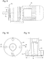
- a commercially available electric drive motor 14 (cf. Fig. 9 ).
- the in Fig. 9 illustrated drive motor 14 to a gear motor for a cutting mill 10 with a Speed range from 50 to 700 rpm.
- Another embodiment of the cutting mill 10 operates with a drive motor 14 without a gearbox for a speed range from 300 to 3000 rpm (not shown).
- the grinding chamber 16 In the front part 12b of the device housing 12 there is the grinding chamber 16, in which the samples to be comminuted or the ground material can be filled in during operation via a filling funnel 18 through a filling opening 19.
- the grinding chamber 16 can be opened from the side by opening the grinding chamber closure cover 20. Furthermore, the grinding chamber 16 can be opened even further by opening a grinding chamber side wall and an upper housing part, sometimes also referred to together as the upper grinding chamber part 21, to which the filling funnel 18 is attached. It should be noted that terms such as “front”, “rear” or “side” relate to the point of view and are therefore not to be understood absolutely.
- the drive motor 14 is flanged to the motor side 24a of the grinding chamber rear wall 24 with a motor flange 22 and threaded bolt 23.
- the motor shaft 26 as the primary shaft runs horizontally and extends through a passage opening 28 in the grinding chamber rear wall 24 and extends into the grinding chamber 16.
- a shaft intermediate piece, which forms the rotor receiving element 30, is placed on the motor shaft 26.
- the torque transmission between the motor shaft 26 and the rotor receiving element 30 is brought about by a form fit, for example by means of a feather key 32.
- the torque is accordingly transmitted from the motor shaft 26 directly to the rotor receiving element 30 by means of the feather key 32.
- the rotor receiving element 30 has a driver flange 34 on the motor side, the diameter of which is considerably larger than the diameter of the motor shaft 26.
- eccentrically arranged driver pins 36 are fastened in the driver flange 34, by means of which the torque is transmitted to the cutting rotor 38. Due to the relatively large distance between the driver pins 36 and the axis of rotation A, a large torque can be transmitted to the cutting rotor 38.
- the cutting rotor 38 has corresponding receiving bores 40 for the positive engagement of the driver pins 36 in the cutting rotor 38.
- the rotor receiving element 30 and the In this example, the motor shaft 26 (which can also be referred to as the primary shaft) together form the drive shaft 42 for the cutting rotor 38.
- the driver flange 34 of the rotor receiving element 30 or the drive shaft 42 runs at least partially within the grinding chamber rear wall 24 or within the passage opening 28. Therefore, in this example, the diameter of the passage opening 28 is also relatively large, which in turn results in a relatively large diameter of the seal of the passage opening 28 requires.
- the grinding chamber rear wall 24 is designed in two parts and consists of a body part 44 made of aluminum and a plate 46 made of stainless steel on or inserted on the grinding chamber side.
- the cutting rotor 38 has a cutting rotor core 48 which is pushed onto the drive shaft 42 and has rotor blades 50 extending axially on the circumferential side of the cutting rotor core 48 ( Fig. 4 ).
- the rotor blades 50 are integrally formed.
- the rotor cutters 50 can, however, also be produced as separate cutting bars, possibly from a different material than the cutting rotor core 48, and connected to the cutting rotor core 48.
- the cutting rotor core 48 can also be designed in two or more parts (not shown).
- the cutting rotor 38 can also be designed as a disk rotor, if necessary with indexable inserts (not shown).
- the cutting rotor 38 rotates horizontally, that is to say about a horizontal axis A. On the motor side, the cutting rotor 38 is mounted on the drive shaft 42.
- the cutting rotor 38 is supported by a support bearing element 54 in the form of a conical bearing element, which in turn is rotatably supported in a ball bearing 56 in the grinding chamber closure cover 20.
- the cutting rotor 38 comprises a support bearing element receptacle 55, which is designed here as a conical bearing element receptacle.
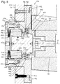
- the grinding chamber 16 is sealed to the grinding chamber closure cover 20 by means of a first labyrinth seal 160.
- the cutting mill comminutes the ground material or the sample by cutting action between the essentially axially extending cutting edges 50 of the cutting rotor 38 and the also essentially axially extending stationary counter-cutting edges 52.
- the cutting mill 10 thus works according to the scissors principle, in which the sample is placed between a pair of cutting edges 50, 52 is cut.
- "essentially axially extending" cutting edge or "axially extending" cutting edge does not necessarily mean that the cutting edges 50, 52 must run exactly parallel to the axis of rotation A, the cutting edges 50, 52 can also run axially obliquely (with twist), as in the case of the in the Fig. 2 and 4th illustrated example of a cutting rotor 38.
- the example shown shows a cutting rotor 38 with so-called V-shaped cutting edges 50.
- these cutting edges 50 also run obliquely (with a twist) but still axially or essentially axially, ie at least not transversely or perpendicular to the axis of rotation A.
- the V-shaped cutting edges 50 of the cutting rotor 38 extend in principle along an acute-angled helical line, which, however, by and large can still be defined as an axial or essentially axial course.
- Below the cutting rotor 38 there is a sieve cassette 92 through which the ground material, which has been sufficiently finely comminuted, can trickle out into the collecting container 94.
- the grinding chamber closure cover 20 can be opened, which means that the grinding chamber 16 is accessible at the front for removing the cutting rotor 38 when the grinding chamber closure cover 20 is open. Folding away the upper part 21 of the grinding chamber also improves the accessibility of the open grinding chamber 16.
- the cutting rotor 38 can be manually pulled horizontally off the drive shaft 42. For this purpose, the cutting rotor 38 is only pushed axially onto the drive shaft 42 and is axially tensioned against the drive shaft 42 by the support bearing element 54 when the grinding chamber closure cover 20 is closed.
- the cutting rotor 38 is merely rotationally coupled to the drive shaft 42 in a form-fitting manner via the driver pins 36 and can be pulled off the drive shaft 42 without a tool after the grinding chamber closure cover 20 has been opened.
- the cutting rotor 38 is thus pressed in the direction of the rotor receiving element 30 and there sits on the likewise conical counterpart 29 of the conical support bearing element 54.
- the small conical section 29 of the rotor receiving element 30 is, for example, in Fig. 6 and 11 shown. The cutting rotor 38 is thus clamped between the two cones 29 and 54.
- the torque transmission by means of the driving pins 36 is relatively far outside, which means that sealing is carried out on a very large diameter.
- the diameter of the circular ring on which the driving pins 36 are arranged is 56.5 mm in this example, and therefore with a driving pin diameter of 8 mm the outer outside diameter is 64.5 mm.
- the radially outer limit of the driver pins 36 is 32.25 mm radially away from the axis of rotation A.
- a large diameter for the seal disadvantageously means a relatively high circumferential speed of the seal compared to a seal that would hypothetically be closer to the axis of rotation A.
- the rotor mount could only be removed with great effort, and typically not for regular cleaning.
- the seal was made with felt rings, for example, which were cumbersome to replace. With these felt rings it could happen that they could lead to a sticking, e.g. due to waxes, oils or resins, which can be separated from the ground material.
- the cutting mill 10 now also has a second labyrinth seal 60 which can be easily removed by the user, for example for cleaning.
- the second labyrinth seal 60 has an inner labyrinth ring 62 which, in this example, is placed as a separate part on the drive shaft 42, more precisely on the driver flange 34.
- the inner labyrinth ring 62 of the second labyrinth seal 60 extends circumferentially completely around the drive shaft 42 or the driver flange 34, has labyrinth-shaped elements 60b in the form of a meander shape 64b on its grinding chamber-side front 62b and rotates with the drive shaft 42.
- the inner labyrinth ring 62 lies there radially outside of the torque-transmitting driver pins 36.
- the rotor receiving element 30 or the driver flange 34 directly with corresponding labyrinth shapes on the grinding chamber side and / or on the motor side or to form meanderings, ie to produce the rotor receiving element 30 and the inner labyrinth ring 62 in one piece.
- a grinding chamber-side labyrinth ring cover 66 is embedded in a corresponding recess 68 as a labyrinth receptacle in the grinding chamber rear wall 24 or the stainless steel attachment plate 46.
- the labyrinth ring cover 66 on the grinding chamber side and the grinding chamber rear wall 24 or the stainless steel plate 46 run flush in order to jointly form an essentially flat inner side 24b of the grinding chamber rear wall in the region of the cutting rotor 38.
- the rotor receiving element 30 is fastened to the motor shaft 26 by means of a central screw 31, although this is not absolutely necessary depending on the embodiment.
- the rotor receiving element 30 sits with a typical transition fit, i.e. tightly clamped, on the motor shaft or primary shaft 26, but can nevertheless be withdrawn from the primary shaft 26 axially in the direction of the open grinding chamber closure cover 20, while overcoming the clamping force of the primary shaft 26, if the possibly existing screw has been loosened.
- the rotor receiving element 30 has a central bore 33 for the central fastening screw 31.
- the bore 33 can be designed as a threaded bore with a larger thread diameter. Then, for example, a corresponding threaded screw in the threaded hole 33 can be used for pulling off (not shown).
- the inner labyrinth ring 62 and with it on the labyrinth ring cover 66 on the grinding chamber side is also pulled off, so that afterwards the passage opening 28 in the grinding chamber rear wall 24 is relatively easily accessible in a ring around the primary shaft 26, e.g. to clean it.
- the rotor receiving element 30 automatically takes the second labyrinth seal 60 with it when it is pulled off the primary shaft 26.
- the rotor receiving element 30, the inner labyrinth ring 62 and / or the grinding chamber-side labyrinth ring cover 66 can be separated and cleaned, for example in an ultrasonic bath.
- the labyrinth receptacle 68 for the second After pulling off the rotor receiving element 30 with the inner labyrinth ring 62 and the labyrinth ring cover 66 on the grinding chamber side, the labyrinth seal 60 is easily accessible from the opened grinding chamber 16 and can also be cleaned.
- the second labyrinth seal 60 designed in this way is therefore advantageously maintenance-friendly, since it is easy to clean on the one hand and is very durable on the other hand, since the mutually rotating parts of the second labyrinth seal 60, i.e. the inner labyrinth ring 62 rotating with the cutting rotor on the one hand and the stationary grinding chamber side Labyrinth ring cover 66 on the other hand, as in the case of the first labyrinth seal 160 described in more detail below, do not touch, but work according to the principle of the gap seal, ie there is an air gap between the intermingled labyrinth shaped elements 60a, 60b.
- the heat development at the second labyrinth seal 60 is low despite the relatively large seal diameter at this point, since the second labyrinth seal 60 is a non-contacting gap seal and, as long as the gap remains clean, no increased friction is generated here.
- the seal on the rotor receiving element 30 or the driver flange 34 as in previous seals, can run far outwards, so that compatibility with older cutting rotors can be maintained.
- the parts of the grinding chamber rear wall 24 directly facing the grinding chamber 16, i.e. at least the plate 46 and the labyrinth ring cover 66 embedded therein can be made of stainless steel, so that, for example, FDA compatibility is possible.
- the second labyrinth seal 60 has additional radial labyrinth-shaped elements 82 in the form of radially circumferential grooves.
- the inner labyrinth ring 62 used for this has on its radially outer circumference 62c accordingly meander-shaped formations formed by the grooves 82.
- the meandering formations are formed by two rings 84, 86 which are triangular in axial cross section.
- the radially circumferential outer surface 62c of the inner labyrinth ring 62 is accordingly provided with sharp-edged tips.
- this geometry can form eddies which can cause air cushions and thus the passage of Particles from the grinding chamber 16 in the direction of the area surrounding the motor 14 can be difficult or prevented.
- One advantage of this inner labyrinth ring 62 is that it can be manufactured as a pure turned part and does not need to be milled.
- the labyrinth receptacle 68 has no counter-labyrinth rings engaging in the grooves 82 or spaces between the projections 84, 86, so that one can speak of an open labyrinth on the circumferential side or a viewing labyrinth.
- the radially outwardly extending annular projections 84, 86 are not interlocked with corresponding counter-labyrinth elements.
- the inner labyrinth ring 62 can thus be pulled axially out of the passage opening 28 or the labyrinth receptacle 68.
- the grinding chamber-side labyrinth ring cover 66 is inserted in a form-fitting manner with an O-ring 88 in a clamping manner into the recess 68 or into the plate 46.
- the elastic O-ring 88 ensures, on the one hand, that the labyrinth ring cover 66 is clamped in the grinding chamber rear wall 24, but also allows the rotor receiving element 30 to be pulled out axially together with the inner labyrinth ring 62 and the labyrinth ring cover 66 on the grinding chamber side, overcoming the forces caused by the O-ring 88 Clamping force too.
- the user can therefore pull the parts 30, 62 and 66 out of the passage opening 28 with appropriate axial force to overcome the clamping force of the clamping, so that the passage opening 28 and the labyrinth receptacle 68 are accessible for cleaning at the front.
- the second labyrinth seal 60 can be pulled apart axially relatively easily, in particular by hand, in order to be cleaned.
- the grinding chamber 16 has a further labyrinth seal on the side of the grinding chamber closure cover 20, which is referred to here as the first labyrinth seal 160.
- the first labyrinth seal 160 on the grinding chamber closure lid 20 seals the grinding chamber 16 against the area of the grinding chamber closure lid 20 in which the mounting of the cutting rotor 38 on the closure lid side is located, which in the present example is accomplished by the ball bearing 56.
- the grinding chamber closure cover 20 is constructed in several parts and has an outer cover part 122 with a central opening, as well as an inner cover part 124 inserted therein.
- the outer cover part 122 forms the main part of the Grinding chamber closure cover 20, in the form of an aluminum door.
- the inner annular cover part 124 has an annular projection 126 which is directed axially away from the grinding chamber 16 and which engages from the inside into a central opening 128 of the outer cover part 122.
- the inner cover part 124 is closed from the outside by means of a central attachment cover 130.
- the central top cover 130 is fastened from the outside, in this example by means of screws 132, on the grinding chamber closure cover 20, more precisely on the inner cover part 124, so that it can be loosened and removed from the outside.
- the painting chamber closure cover 20 or the inner cover part 124 and the central closure cover 130 accommodate the ball bearing 56 and enable it to be installed and removed from the outside.
- the ball bearing 56 is designed as a double-row angular contact ball bearing. "Inclined" because of the better absorption of axial force. Twice so that the angular play is significantly reduced compared to a simple deep groove ball bearing.
- the ball bearing 56 is axially acted upon by force in the direction of the grinding chamber 16 by a spring 140, which in the present example is designed as a spring assembly made up of two oppositely layered cup springs.
- the spring 140 is supported on the central attachment cover 130, that is to say, viewed generally, on an inner side of the grinding chamber closure cover 20.
- the support bearing element 54 which in the present example has a bearing fit in the form of a cone 156 on the grinding chamber side and a bearing extension 158 pointing away from the grinding chamber 16, is rotatably mounted on the grinding chamber closure cover 20 by means of the ball bearing 56.
- the support bearing element 54 is by and large mushroom-shaped and the bearing extension 158 is mounted in the ball bearing 56.
- the cone 156 on the grinding chamber side matured to fit into the conical support bearing element receptacle 55 of the cutting rotor 38, in order to clamp the cutting rotor 38 on the closure cover side and to form the counter bearing for the motor shaft 26.
- an O-ring 152 is inserted in a circumferential annular groove 150, with which the support bearing element 54 is held in a clamping manner in the ball bearing 56 so that it does not fall out when the grinding chamber closure cover 20 is opened. Nevertheless, the support bearing element 54 can through a central bore 154 in the grinding chamber closure cover 20, more precisely in the central cover attachment 130, for example by means of a bolt or screwdriver while overcoming the clamping or frictional force caused by the O-ring 152, when the grinding chamber closure cover 20 is opened.
- a grinding chamber-side or inner labyrinth ring 162 of the first labyrinth seal 160 is supported axially on an annular stop 172 of the support bearing element 54. When the support bearing element 54 is pushed out, the labyrinth ring 162 on the grinding chamber side is also pushed out as a result.
- the inner labyrinth ring 162 engages with its axial labyrinth shape elements 182 in the form of two annular axial projections 182a, 182b in corresponding axial labyrinth shape elements 184 in the form of axial grooves 184a, 184b of the outer labyrinth ring 164.
- the axial shaped labyrinth elements 182 of the inner labyrinth ring 162 are axially meshed with the axial labyrinth shaped elements 184 of the outer labyrinth ring 164.
- the axial gap 204 of the labyrinth seal 160 is considerably larger than the radial gap 205.
- the first labyrinth seal 160 has sufficient axial play to allow the bearing on the closure cover to spring in when the grinding chamber is closed.
- the support bearing element 54 presses against the support bearing element receptacle 55 in order to axially brace the cutting rotor 38.
- the support bearing element 54 tensions the spring 140 via the ball bearing 56.
- the spring tension of the spring 140 ensures that the ball bearing 56 is moved in the direction of the cutting rotor 38 until it stops a stop 190 of the grinding chamber closure cover 20, more precisely of the inner cover part 124, strikes.
- the ball bearing 56 detaches axially from the stop 190 when the support bearing element 54 with the ball bearing 56 compresses against the spring 140 away from the cutting rotor 38, so that the ball bearing 56 is not excessively stressed during operation during rotation.
- the outer labyrinth ring 164 is not designed as a separate part, but is screwed integrally into the grinding chamber closure cover 20, more precisely into the inner cover part 124, whereby a separate component can be saved.
- Both the inner cover part 124 and the inner labyrinth ring 162, and thus the second labyrinth seal 160 are preferably made of stainless steel and / or manufactured as turned parts, which offers advantages in terms of administrative approvals and, on the other hand, is inexpensive to manufacture.
- the grinding chamber closure cover 20 seals against the end face of the housing part 12b surrounding the grinding chamber 16 by means of an O-ring 192.
- the support bearing element 54 has further labyrinth-shaped elements 194 on its radial outer side 54a.
- the radially circumferential labyrinth shaped elements 194 are formed in the present example by grooves 196, between which radially circumferential projections 198 are formed in relation to the grooves 196.
- the radially circumferential projections 198 have a triangular cross section and are pointed radially on the outside in order to generate flow vortices, if necessary, which can improve the sealing effect.
- the receiving opening 202 for the support bearing element 54 in the grinding chamber closure cover 20, more precisely in the inner cover part 124, on the other hand, does not have any labyrinth shaped elements interlocked with the labyrinth shaped elements 194 of the support bearing element 54.
- the penetration opening 202 is smooth on its inside, so that the radial labyrinth shape elements 194 of the support bearing element 54 together with the opening 202 form an open (radially non-interlocked) labyrinth or a viewing labyrinth.
- the support bearing element 54 can be pushed axially inward out of the grinding chamber closure cover 20 without complex dismantling.
- the support bearing element 54 takes the inner labyrinth ring 162 with it via the stop 172. Subsequently, both the labyrinth sealing surfaces and at least some of the ball bearing 56 are exposed, so that cleaning is simplified.
- the support bearing element 54 and the inner labyrinth ring 162 can after removal in one Be cleaned in the ultrasonic bath.
- a reverse geometry of the radial view labyrinth is also possible, in that the radial labyrinth shaped elements 194 are arranged radially on the inside in the opening 202 instead of radially on the outside on the support bearing element 54.
- a radially uncombed or see-through labyrinth is formed by radial shaped elements 194 either on the radial outer circumference of the support bearing element 54 or on a radial inner circumference of the grinding chamber closure cover 20.
- the Fig. 12 shows the open state of the grinding chamber closure cover 20, in which the spring 140 tensions the ball bearing 56 against the axial stop 190. In this state, the spring 140 is the least tensioned and the first labyrinth seal 160 has the maximum axial gap dimension 204.
- Fig. 13 the closed state of the grinding chamber closure cover 20 is shown, in which the support bearing element 54 tensions the ball bearing 56 against the spring 140 by means of an axial stop 206 resting on the ball bearing 56 and is correspondingly compressed.
- the support bearing element 54 tensions this with its axial annular stop 206 against the inner end face of the ball bearing 56 in order to tension it against the spring 140 and thus forms an axial counter-bearing for the spring 140.
- the axial gap dimension 204 of the first labyrinth seal 160 is smaller than in the open state according to Fig. 12 .
- the first labyrinth seal 160 thus has an axial displaceability of the intermeshed labyrinth shaped elements 182, 184, whereby the compression of the support bearing element 54, which occurs when the cutting rotor 38 is clamped or the grinding chamber closure cover 20 is closed, can be compensated for.
- the Fig. 14 shows a maximum extreme state in which the maximum deflection of the support bearing element 54 and the ball bearing 56 is shown, so that the axial play of the first labyrinth seal 160 in the form of the axial gap 204 is completely consumed. This State in which the first labyrinth seal 160 would rub should not be reached during operation.
- the first labyrinth seal 160 has labyrinth-shaped elements 182, 184 intermeshed with one another axially for a relatively long time, on the one hand to achieve a good labyrinth sealing effect and on the other hand to allow sufficient axial play or sufficient axial spring travel to be able to compensate, for example, axial tolerances of the cutting rotor 38 .
- the aspect ratio of the axially intermingled labyrinth shaped elements 182, 184 is greater than 1, preferably greater than 2, in the present example approximately between 3 and 4.
- the support bearing element 54 or so-called cone support bearing that has to absorb the length tolerances that occur between itself and the motor output shaft.
- the cutting rotor 38 is pushed in the direction of the drive motor 14 with a force of, for example, 1000 N. This force should also be applied reliably and, due to the spring travel of the spring 140 that is necessary for this, causes further axial length tolerances.
- the plug-in solution described for the support bearing element 54 instead of a screw connection also offers the advantage that the support bearing element 54, which carries one of the two labyrinth rings, can be pushed out of its receptacle in the direction of the grinding chamber 16 without for example having to loosen a screw connection.
- the clamping element between the support bearing element 54 in the grinding chamber closure cover 20 in the form of the additional O-ring 152 ensures that the support bearing element 54 is held in its position in the mounting without having to provide a form fit.
- the support bearing element 54 which is designed as a cone support bearing in the present example, is pushed back in and does not need to be locked further because it is clamped or frictionally engaged in the grinding chamber by the O-ring 152 -Closure cover 20, more precisely in the ball bearing 56 is held.
- the cutting rotor 38 or the axial clamping force also ensures that the support bearing element 54 is clamped axially between the ball bearing 56 and the cutting rotor 38.
- the sealing concept presented here has a number of advantages, e.g. compared to the felt seals previously used.
- the sealing concept is easy to maintain and, on the other hand, hardly requires any maintenance. Nevertheless, the sealing concept keeps dust well in the grinding chamber and allows only a little dust or other contamination to get through the first labyrinth seal to the ball bearing 56 and, if also present, possibly also through the second labyrinth seal in the area of the drive motor 14.
- the sealing concept has a low level of heat development.
- Another advantage is the avoidance of material abrasion (with clean labyrinth seals 60, 160) and the possibility of administrative approvals (e.g. FDA approval), especially if, for example, the parts of the first and / or second labyrinth seal are made of stainless steel.
- the manufacture of such labyrinth seals has proven to be technologically feasible and has surprising advantages. In some regions of the world, for example, efforts are currently being made to increasingly approve cannabis products for various uses. This has led to increased demand for granulators in cannabis processing.
- the first labyrinth seal proposed here in the grinding chamber closure lid 20 can effectively avoid oiling or gumming of the seal, or at least the cleaning options of the Storage on the grinding chamber closure cover 20 is significantly improved.
Landscapes
- Engineering & Computer Science (AREA)
- Food Science & Technology (AREA)
- Crushing And Grinding (AREA)
- Crushing And Pulverization Processes (AREA)
Applications Claiming Priority (1)
| Application Number | Priority Date | Filing Date | Title |
|---|---|---|---|
| DE102019133437.3A DE102019133437A1 (de) | 2019-12-06 | 2019-12-06 | Schneidmühle zum schneidenden Zerkleinern von Proben |
Publications (2)
| Publication Number | Publication Date |
|---|---|
| EP3831494A1 true EP3831494A1 (fr) | 2021-06-09 |
| EP3831494B1 EP3831494B1 (fr) | 2022-08-17 |
Family
ID=73597802
Family Applications (1)
| Application Number | Title | Priority Date | Filing Date |
|---|---|---|---|
| EP20209556.8A Active EP3831494B1 (fr) | 2019-12-06 | 2020-11-24 | Broyeur à découper destiné au broyage par découpage des échantillons |
Country Status (2)
| Country | Link |
|---|---|
| EP (1) | EP3831494B1 (fr) |
| DE (1) | DE102019133437A1 (fr) |
Cited By (2)
| Publication number | Priority date | Publication date | Assignee | Title |
|---|---|---|---|---|
| CN119486815A (zh) * | 2022-06-20 | 2025-02-18 | 飞瑞讯有限公司 | 实验室碾磨机 |
| WO2025088197A1 (fr) * | 2023-10-25 | 2025-05-01 | Retsch Gmbh | Broyeur de laboratoire |
Families Citing this family (2)
| Publication number | Priority date | Publication date | Assignee | Title |
|---|---|---|---|---|
| DE102022115334B4 (de) | 2022-06-20 | 2025-08-14 | Fritsch Gmbh | Labormühle |
| DE102024113618B4 (de) * | 2024-05-15 | 2026-03-12 | Fritsch Gmbh | Labormühle und Mahlguteinfüllstempel für eine Labormühle |
Citations (1)
| Publication number | Priority date | Publication date | Assignee | Title |
|---|---|---|---|---|
| DE29713097U1 (de) * | 1997-07-23 | 1998-11-26 | Fritsch GmbH Laborgerätebau, 55743 Idar-Oberstein | Labormühle mit Befestigungseinrichtung für eine Gutauffangvorrichtung |
Family Cites Families (2)
| Publication number | Priority date | Publication date | Assignee | Title |
|---|---|---|---|---|
| DE19706425C1 (de) * | 1997-02-19 | 1998-04-09 | Fritsch Gmbh Laborgeraetebau | Zerlegbare Laborschneidmühle |
| DE202016005405U1 (de) * | 2016-05-18 | 2017-08-21 | Retsch Gmbh | Mahlbecher und Labormühle mit einem Mahlbecher |
-
2019
- 2019-12-06 DE DE102019133437.3A patent/DE102019133437A1/de not_active Ceased
-
2020
- 2020-11-24 EP EP20209556.8A patent/EP3831494B1/fr active Active
Patent Citations (1)
| Publication number | Priority date | Publication date | Assignee | Title |
|---|---|---|---|---|
| DE29713097U1 (de) * | 1997-07-23 | 1998-11-26 | Fritsch GmbH Laborgerätebau, 55743 Idar-Oberstein | Labormühle mit Befestigungseinrichtung für eine Gutauffangvorrichtung |
Cited By (3)
| Publication number | Priority date | Publication date | Assignee | Title |
|---|---|---|---|---|
| CN119486815A (zh) * | 2022-06-20 | 2025-02-18 | 飞瑞讯有限公司 | 实验室碾磨机 |
| CN119486815B (zh) * | 2022-06-20 | 2026-02-03 | 飞瑞讯有限公司 | 实验室碾磨机 |
| WO2025088197A1 (fr) * | 2023-10-25 | 2025-05-01 | Retsch Gmbh | Broyeur de laboratoire |
Also Published As
| Publication number | Publication date |
|---|---|
| DE102019133437A1 (de) | 2021-06-10 |
| EP3831494B1 (fr) | 2022-08-17 |
Similar Documents
| Publication | Publication Date | Title |
|---|---|---|
| EP3831494B1 (fr) | Broyeur à découper destiné au broyage par découpage des échantillons | |
| EP3584011A1 (fr) | Broyeur à découper destiné au broyage par découpage des échantillons | |
| DE4408049C2 (de) | Zerkleinerungsvorrichtung | |
| EP0329662B1 (fr) | Dispositif de traitement de matieres plastiques | |
| EP3538278B1 (fr) | Broyeur à deux arbres avec jeu de lames de coupe interchangeables et extrémités d'arbre détachables | |
| WO2020200759A1 (fr) | Broyeur à couteaux de laboratoire pour le broyage par découpage d'échantillons | |
| EP2411152A1 (fr) | Dispositif de coupe | |
| DE202020105051U1 (de) | Fleischwolf | |
| EP3711862B1 (fr) | Dispositif de coupe, séparateur, procédé de séparation des ingrédients alimentaires au moyen d'un séparateur | |
| EP3964295A1 (fr) | Hachoir à viande | |
| EP2877069B1 (fr) | Râpe circulaire | |
| EP2371460A2 (fr) | Dispositif de traitement de produits de jardin, de la terrassement ou analogues | |
| EP3079827B1 (fr) | Dispositif de broyage avec plaquette d`usure | |
| DE102008039258A1 (de) | Zerkleinerungsmaschine | |
| DE19508093A1 (de) | Fleischwolf | |
| DE3406285C2 (fr) | ||
| DE202010003036U1 (de) | Feinstzerkleinerer | |
| DE10026825C2 (de) | Zerkleinerungsvorrichtung | |
| EP3515602B1 (fr) | Broyeur fin | |
| DE102018106878B4 (de) | Zerkleinerer mit wenigstens einer Lochscheibe und mit wenigstens einem der Lochscheibe zugeordneten Messer | |
| DE102007025899B4 (de) | Vorrichtung zum Zerkleinern eines Zerkleinerungsgutes | |
| DE10312605B4 (de) | Einrichtung zum Trennen und Abfördern von Rohstoffen | |
| WO2018050809A1 (fr) | Rotor de hachage pour un dispositif de broyage, en particulier hachoir | |
| EP2156772A1 (fr) | Broyeur destiné à broyer des aliments, en particulier du café | |
| CH415334A (de) | Zerkleinerungsmaschine für Fleisch oder andere zerkleinerungsfähige Nahrungsmittel und Genussmittel |
Legal Events
| Date | Code | Title | Description |
|---|---|---|---|
| PUAI | Public reference made under article 153(3) epc to a published international application that has entered the european phase |
Free format text: ORIGINAL CODE: 0009012 |
|
| STAA | Information on the status of an ep patent application or granted ep patent |
Free format text: STATUS: THE APPLICATION HAS BEEN PUBLISHED |
|
| AK | Designated contracting states |
Kind code of ref document: A1 Designated state(s): AL AT BE BG CH CY CZ DE DK EE ES FI FR GB GR HR HU IE IS IT LI LT LU LV MC MK MT NL NO PL PT RO RS SE SI SK SM TR |
|
| STAA | Information on the status of an ep patent application or granted ep patent |
Free format text: STATUS: REQUEST FOR EXAMINATION WAS MADE |
|
| 17P | Request for examination filed |
Effective date: 20211203 |
|
| RBV | Designated contracting states (corrected) |
Designated state(s): AL AT BE BG CH CY CZ DE DK EE ES FI FR GB GR HR HU IE IS IT LI LT LU LV MC MK MT NL NO PL PT RO RS SE SI SK SM TR |
|
| GRAP | Despatch of communication of intention to grant a patent |
Free format text: ORIGINAL CODE: EPIDOSNIGR1 |
|
| STAA | Information on the status of an ep patent application or granted ep patent |
Free format text: STATUS: GRANT OF PATENT IS INTENDED |
|
| RIC1 | Information provided on ipc code assigned before grant |
Ipc: B02C 18/16 20060101ALI20220405BHEP Ipc: B02C 18/14 20060101AFI20220405BHEP |
|
| INTG | Intention to grant announced |
Effective date: 20220509 |
|
| GRAS | Grant fee paid |
Free format text: ORIGINAL CODE: EPIDOSNIGR3 |
|
| GRAA | (expected) grant |
Free format text: ORIGINAL CODE: 0009210 |
|
| STAA | Information on the status of an ep patent application or granted ep patent |
Free format text: STATUS: THE PATENT HAS BEEN GRANTED |
|
| AK | Designated contracting states |
Kind code of ref document: B1 Designated state(s): AL AT BE BG CH CY CZ DE DK EE ES FI FR GB GR HR HU IE IS IT LI LT LU LV MC MK MT NL NO PL PT RO RS SE SI SK SM TR |
|
| REG | Reference to a national code |
Ref country code: CH Ref legal event code: EP |
|
| REG | Reference to a national code |
Ref country code: DE Ref legal event code: R096 Ref document number: 502020001545 Country of ref document: DE |
|
| REG | Reference to a national code |
Ref country code: IE Ref legal event code: FG4D Free format text: LANGUAGE OF EP DOCUMENT: GERMAN |
|
| REG | Reference to a national code |
Ref country code: AT Ref legal event code: REF Ref document number: 1511808 Country of ref document: AT Kind code of ref document: T Effective date: 20220915 |
|
| REG | Reference to a national code |
Ref country code: NL Ref legal event code: MP Effective date: 20220817 |
|
| REG | Reference to a national code |
Ref country code: LT Ref legal event code: MG9D |
|
| PG25 | Lapsed in a contracting state [announced via postgrant information from national office to epo] |
Ref country code: SE Free format text: LAPSE BECAUSE OF FAILURE TO SUBMIT A TRANSLATION OF THE DESCRIPTION OR TO PAY THE FEE WITHIN THE PRESCRIBED TIME-LIMIT Effective date: 20220817 Ref country code: RS Free format text: LAPSE BECAUSE OF FAILURE TO SUBMIT A TRANSLATION OF THE DESCRIPTION OR TO PAY THE FEE WITHIN THE PRESCRIBED TIME-LIMIT Effective date: 20220817 Ref country code: PT Free format text: LAPSE BECAUSE OF FAILURE TO SUBMIT A TRANSLATION OF THE DESCRIPTION OR TO PAY THE FEE WITHIN THE PRESCRIBED TIME-LIMIT Effective date: 20221219 Ref country code: NO Free format text: LAPSE BECAUSE OF FAILURE TO SUBMIT A TRANSLATION OF THE DESCRIPTION OR TO PAY THE FEE WITHIN THE PRESCRIBED TIME-LIMIT Effective date: 20221117 Ref country code: NL Free format text: LAPSE BECAUSE OF FAILURE TO SUBMIT A TRANSLATION OF THE DESCRIPTION OR TO PAY THE FEE WITHIN THE PRESCRIBED TIME-LIMIT Effective date: 20220817 Ref country code: LV Free format text: LAPSE BECAUSE OF FAILURE TO SUBMIT A TRANSLATION OF THE DESCRIPTION OR TO PAY THE FEE WITHIN THE PRESCRIBED TIME-LIMIT Effective date: 20220817 Ref country code: LT Free format text: LAPSE BECAUSE OF FAILURE TO SUBMIT A TRANSLATION OF THE DESCRIPTION OR TO PAY THE FEE WITHIN THE PRESCRIBED TIME-LIMIT Effective date: 20220817 Ref country code: FI Free format text: LAPSE BECAUSE OF FAILURE TO SUBMIT A TRANSLATION OF THE DESCRIPTION OR TO PAY THE FEE WITHIN THE PRESCRIBED TIME-LIMIT Effective date: 20220817 |
|
| PG25 | Lapsed in a contracting state [announced via postgrant information from national office to epo] |
Ref country code: PL Free format text: LAPSE BECAUSE OF FAILURE TO SUBMIT A TRANSLATION OF THE DESCRIPTION OR TO PAY THE FEE WITHIN THE PRESCRIBED TIME-LIMIT Effective date: 20220817 Ref country code: IS Free format text: LAPSE BECAUSE OF FAILURE TO SUBMIT A TRANSLATION OF THE DESCRIPTION OR TO PAY THE FEE WITHIN THE PRESCRIBED TIME-LIMIT Effective date: 20221217 Ref country code: HR Free format text: LAPSE BECAUSE OF FAILURE TO SUBMIT A TRANSLATION OF THE DESCRIPTION OR TO PAY THE FEE WITHIN THE PRESCRIBED TIME-LIMIT Effective date: 20220817 Ref country code: GR Free format text: LAPSE BECAUSE OF FAILURE TO SUBMIT A TRANSLATION OF THE DESCRIPTION OR TO PAY THE FEE WITHIN THE PRESCRIBED TIME-LIMIT Effective date: 20221118 |
|
| PG25 | Lapsed in a contracting state [announced via postgrant information from national office to epo] |
Ref country code: SM Free format text: LAPSE BECAUSE OF FAILURE TO SUBMIT A TRANSLATION OF THE DESCRIPTION OR TO PAY THE FEE WITHIN THE PRESCRIBED TIME-LIMIT Effective date: 20220817 Ref country code: RO Free format text: LAPSE BECAUSE OF FAILURE TO SUBMIT A TRANSLATION OF THE DESCRIPTION OR TO PAY THE FEE WITHIN THE PRESCRIBED TIME-LIMIT Effective date: 20220817 Ref country code: ES Free format text: LAPSE BECAUSE OF FAILURE TO SUBMIT A TRANSLATION OF THE DESCRIPTION OR TO PAY THE FEE WITHIN THE PRESCRIBED TIME-LIMIT Effective date: 20220817 Ref country code: DK Free format text: LAPSE BECAUSE OF FAILURE TO SUBMIT A TRANSLATION OF THE DESCRIPTION OR TO PAY THE FEE WITHIN THE PRESCRIBED TIME-LIMIT Effective date: 20220817 Ref country code: CZ Free format text: LAPSE BECAUSE OF FAILURE TO SUBMIT A TRANSLATION OF THE DESCRIPTION OR TO PAY THE FEE WITHIN THE PRESCRIBED TIME-LIMIT Effective date: 20220817 |
|
| REG | Reference to a national code |
Ref country code: DE Ref legal event code: R097 Ref document number: 502020001545 Country of ref document: DE |
|
| PG25 | Lapsed in a contracting state [announced via postgrant information from national office to epo] |
Ref country code: SK Free format text: LAPSE BECAUSE OF FAILURE TO SUBMIT A TRANSLATION OF THE DESCRIPTION OR TO PAY THE FEE WITHIN THE PRESCRIBED TIME-LIMIT Effective date: 20220817 Ref country code: EE Free format text: LAPSE BECAUSE OF FAILURE TO SUBMIT A TRANSLATION OF THE DESCRIPTION OR TO PAY THE FEE WITHIN THE PRESCRIBED TIME-LIMIT Effective date: 20220817 |
|
| PLBE | No opposition filed within time limit |
Free format text: ORIGINAL CODE: 0009261 |
|
| STAA | Information on the status of an ep patent application or granted ep patent |
Free format text: STATUS: NO OPPOSITION FILED WITHIN TIME LIMIT |
|
| PG25 | Lapsed in a contracting state [announced via postgrant information from national office to epo] |
Ref country code: MC Free format text: LAPSE BECAUSE OF FAILURE TO SUBMIT A TRANSLATION OF THE DESCRIPTION OR TO PAY THE FEE WITHIN THE PRESCRIBED TIME-LIMIT Effective date: 20220817 Ref country code: AL Free format text: LAPSE BECAUSE OF FAILURE TO SUBMIT A TRANSLATION OF THE DESCRIPTION OR TO PAY THE FEE WITHIN THE PRESCRIBED TIME-LIMIT Effective date: 20220817 |
|
| 26N | No opposition filed |
Effective date: 20230519 |
|
| REG | Reference to a national code |
Ref country code: BE Ref legal event code: MM Effective date: 20221130 |
|
| PG25 | Lapsed in a contracting state [announced via postgrant information from national office to epo] |
Ref country code: SI Free format text: LAPSE BECAUSE OF FAILURE TO SUBMIT A TRANSLATION OF THE DESCRIPTION OR TO PAY THE FEE WITHIN THE PRESCRIBED TIME-LIMIT Effective date: 20220817 Ref country code: LU Free format text: LAPSE BECAUSE OF NON-PAYMENT OF DUE FEES Effective date: 20221124 |
|
| PG25 | Lapsed in a contracting state [announced via postgrant information from national office to epo] |
Ref country code: IE Free format text: LAPSE BECAUSE OF NON-PAYMENT OF DUE FEES Effective date: 20221124 |
|
| PG25 | Lapsed in a contracting state [announced via postgrant information from national office to epo] |
Ref country code: BE Free format text: LAPSE BECAUSE OF NON-PAYMENT OF DUE FEES Effective date: 20221130 |
|
| PG25 | Lapsed in a contracting state [announced via postgrant information from national office to epo] |
Ref country code: CY Free format text: LAPSE BECAUSE OF FAILURE TO SUBMIT A TRANSLATION OF THE DESCRIPTION OR TO PAY THE FEE WITHIN THE PRESCRIBED TIME-LIMIT Effective date: 20220817 |
|
| PG25 | Lapsed in a contracting state [announced via postgrant information from national office to epo] |
Ref country code: MK Free format text: LAPSE BECAUSE OF FAILURE TO SUBMIT A TRANSLATION OF THE DESCRIPTION OR TO PAY THE FEE WITHIN THE PRESCRIBED TIME-LIMIT Effective date: 20220817 Ref country code: IT Free format text: LAPSE BECAUSE OF FAILURE TO SUBMIT A TRANSLATION OF THE DESCRIPTION OR TO PAY THE FEE WITHIN THE PRESCRIBED TIME-LIMIT Effective date: 20220817 |
|
| PG25 | Lapsed in a contracting state [announced via postgrant information from national office to epo] |
Ref country code: TR Free format text: LAPSE BECAUSE OF FAILURE TO SUBMIT A TRANSLATION OF THE DESCRIPTION OR TO PAY THE FEE WITHIN THE PRESCRIBED TIME-LIMIT Effective date: 20220817 |
|
| REG | Reference to a national code |
Ref country code: CH Ref legal event code: PL |
|
| PG25 | Lapsed in a contracting state [announced via postgrant information from national office to epo] |
Ref country code: CH Free format text: LAPSE BECAUSE OF NON-PAYMENT OF DUE FEES Effective date: 20231130 |
|
| PG25 | Lapsed in a contracting state [announced via postgrant information from national office to epo] |
Ref country code: CH Free format text: LAPSE BECAUSE OF NON-PAYMENT OF DUE FEES Effective date: 20231130 Ref country code: BG Free format text: LAPSE BECAUSE OF FAILURE TO SUBMIT A TRANSLATION OF THE DESCRIPTION OR TO PAY THE FEE WITHIN THE PRESCRIBED TIME-LIMIT Effective date: 20220817 |
|
| PG25 | Lapsed in a contracting state [announced via postgrant information from national office to epo] |
Ref country code: MT Free format text: LAPSE BECAUSE OF FAILURE TO SUBMIT A TRANSLATION OF THE DESCRIPTION OR TO PAY THE FEE WITHIN THE PRESCRIBED TIME-LIMIT Effective date: 20220817 |
|
| PG25 | Lapsed in a contracting state [announced via postgrant information from national office to epo] |
Ref country code: HU Free format text: LAPSE BECAUSE OF FAILURE TO SUBMIT A TRANSLATION OF THE DESCRIPTION OR TO PAY THE FEE WITHIN THE PRESCRIBED TIME-LIMIT; INVALID AB INITIO Effective date: 20201124 |
|
| PGFP | Annual fee paid to national office [announced via postgrant information from national office to epo] |
Ref country code: DE Payment date: 20251125 Year of fee payment: 6 |
|
| PGFP | Annual fee paid to national office [announced via postgrant information from national office to epo] |
Ref country code: GB Payment date: 20251120 Year of fee payment: 6 |
|
| PGFP | Annual fee paid to national office [announced via postgrant information from national office to epo] |
Ref country code: AT Payment date: 20260113 Year of fee payment: 5 |
|
| PGFP | Annual fee paid to national office [announced via postgrant information from national office to epo] |
Ref country code: FR Payment date: 20251120 Year of fee payment: 6 |