EP3831719A1 - Rückwärtige verkleidung einer motorsäule eines luftfahrzeugs mit mehrschichtigem wärmeschutzschild - Google Patents
Rückwärtige verkleidung einer motorsäule eines luftfahrzeugs mit mehrschichtigem wärmeschutzschild Download PDFInfo
- Publication number
- EP3831719A1 EP3831719A1 EP20210751.2A EP20210751A EP3831719A1 EP 3831719 A1 EP3831719 A1 EP 3831719A1 EP 20210751 A EP20210751 A EP 20210751A EP 3831719 A1 EP3831719 A1 EP 3831719A1
- Authority
- EP
- European Patent Office
- Prior art keywords
- heat shield
- engine
- shield
- apf
- skin
- Prior art date
- Legal status (The legal status is an assumption and is not a legal conclusion. Google has not performed a legal analysis and makes no representation as to the accuracy of the status listed.)
- Granted
Links
Images





Classifications
-
- B—PERFORMING OPERATIONS; TRANSPORTING
- B32—LAYERED PRODUCTS
- B32B—LAYERED PRODUCTS, i.e. PRODUCTS BUILT-UP OF STRATA OF FLAT OR NON-FLAT, e.g. CELLULAR OR HONEYCOMB, FORM
- B32B3/00—Layered products comprising a layer with external or internal discontinuities or unevennesses, or a layer of non-planar shape; Layered products comprising a layer having particular features of form
- B32B3/10—Layered products comprising a layer with external or internal discontinuities or unevennesses, or a layer of non-planar shape; Layered products comprising a layer having particular features of form characterised by a discontinuous layer, i.e. formed of separate pieces of material
- B32B3/12—Layered products comprising a layer with external or internal discontinuities or unevennesses, or a layer of non-planar shape; Layered products comprising a layer having particular features of form characterised by a discontinuous layer, i.e. formed of separate pieces of material characterised by a layer of regularly- arranged cells, e.g. a honeycomb structure
-
- B—PERFORMING OPERATIONS; TRANSPORTING
- B32—LAYERED PRODUCTS
- B32B—LAYERED PRODUCTS, i.e. PRODUCTS BUILT-UP OF STRATA OF FLAT OR NON-FLAT, e.g. CELLULAR OR HONEYCOMB, FORM
- B32B15/00—Layered products comprising a layer of metal
- B32B15/04—Layered products comprising a layer of metal comprising metal as the main or only constituent of a layer, which is next to another layer of the same or of a different material
- B32B15/046—Layered products comprising a layer of metal comprising metal as the main or only constituent of a layer, which is next to another layer of the same or of a different material of foam
-
- B—PERFORMING OPERATIONS; TRANSPORTING
- B32—LAYERED PRODUCTS
- B32B—LAYERED PRODUCTS, i.e. PRODUCTS BUILT-UP OF STRATA OF FLAT OR NON-FLAT, e.g. CELLULAR OR HONEYCOMB, FORM
- B32B5/00—Layered products characterised by the non- homogeneity or physical structure, i.e. comprising a fibrous, filamentary, particulate or foam layer; Layered products characterised by having a layer differing constitutionally or physically in different parts
- B32B5/18—Layered products characterised by the non- homogeneity or physical structure, i.e. comprising a fibrous, filamentary, particulate or foam layer; Layered products characterised by having a layer differing constitutionally or physically in different parts characterised by features of a layer of foamed material
-
- B—PERFORMING OPERATIONS; TRANSPORTING
- B32—LAYERED PRODUCTS
- B32B—LAYERED PRODUCTS, i.e. PRODUCTS BUILT-UP OF STRATA OF FLAT OR NON-FLAT, e.g. CELLULAR OR HONEYCOMB, FORM
- B32B5/00—Layered products characterised by the non- homogeneity or physical structure, i.e. comprising a fibrous, filamentary, particulate or foam layer; Layered products characterised by having a layer differing constitutionally or physically in different parts
- B32B5/22—Layered products characterised by the non- homogeneity or physical structure, i.e. comprising a fibrous, filamentary, particulate or foam layer; Layered products characterised by having a layer differing constitutionally or physically in different parts characterised by the presence of two or more layers which are next to each other and are fibrous, filamentary, formed of particles or foamed
- B32B5/24—Layered products characterised by the non- homogeneity or physical structure, i.e. comprising a fibrous, filamentary, particulate or foam layer; Layered products characterised by having a layer differing constitutionally or physically in different parts characterised by the presence of two or more layers which are next to each other and are fibrous, filamentary, formed of particles or foamed one layer being a fibrous or filamentary layer
- B32B5/245—Layered products characterised by the non- homogeneity or physical structure, i.e. comprising a fibrous, filamentary, particulate or foam layer; Layered products characterised by having a layer differing constitutionally or physically in different parts characterised by the presence of two or more layers which are next to each other and are fibrous, filamentary, formed of particles or foamed one layer being a fibrous or filamentary layer another layer next to it being a foam layer
-
- B—PERFORMING OPERATIONS; TRANSPORTING
- B32—LAYERED PRODUCTS
- B32B—LAYERED PRODUCTS, i.e. PRODUCTS BUILT-UP OF STRATA OF FLAT OR NON-FLAT, e.g. CELLULAR OR HONEYCOMB, FORM
- B32B9/00—Layered products comprising a layer of a particular substance not covered by groups B32B11/00 - B32B29/00
- B32B9/005—Layered products comprising a layer of a particular substance not covered by groups B32B11/00 - B32B29/00 comprising one layer of ceramic material, e.g. porcelain, ceramic tile
-
- B—PERFORMING OPERATIONS; TRANSPORTING
- B32—LAYERED PRODUCTS
- B32B—LAYERED PRODUCTS, i.e. PRODUCTS BUILT-UP OF STRATA OF FLAT OR NON-FLAT, e.g. CELLULAR OR HONEYCOMB, FORM
- B32B2262/00—Composition or structural features of fibres which form a fibrous or filamentary layer or are present as additives
- B32B2262/10—Inorganic fibres
- B32B2262/106—Carbon fibres, e.g. graphite fibres
-
- B—PERFORMING OPERATIONS; TRANSPORTING
- B64—AIRCRAFT; AVIATION; COSMONAUTICS
- B64D—EQUIPMENT FOR FITTING IN OR TO AIRCRAFT; FLIGHT SUITS; PARACHUTES; ARRANGEMENT OR MOUNTING OF POWER PLANTS OR PROPULSION TRANSMISSIONS IN AIRCRAFT
- B64D29/00—Power-plant nacelles, fairings or cowlings
- B64D29/02—Power-plant nacelles, fairings or cowlings associated with wings
-
- B—PERFORMING OPERATIONS; TRANSPORTING
- B64—AIRCRAFT; AVIATION; COSMONAUTICS
- B64D—EQUIPMENT FOR FITTING IN OR TO AIRCRAFT; FLIGHT SUITS; PARACHUTES; ARRANGEMENT OR MOUNTING OF POWER PLANTS OR PROPULSION TRANSMISSIONS IN AIRCRAFT
- B64D33/00—Arrangement in aircraft of power plant parts or auxiliaries not otherwise provided for
- B64D33/04—Arrangement in aircraft of power plant parts or auxiliaries not otherwise provided for of exhaust outlets or jet pipes
- B64D33/06—Silencing exhaust or propulsion jets
Definitions
- the present invention relates to the field of aircraft engine mounting masts (also called pylons), hereinafter referred to more succinctly as an engine mast; it relates more specifically to a rear fairing of such an engine pylon.
- aircraft engine mounting masts also called pylons
- a nacelle, an engine or an engine pylon (whether it is a device of the prior art or a device according to the invention) is observed as arranged in an aircraft.
- the central axis of a nacelle (which coincides with the axis of revolution of the engine it contains), as well as the main axis of an engine mast, being parallel to the X axis of roll of the aircraft when the nacelle or the mast is mounted in the aircraft
- the terms “ longitudinal direction of a nacelle or mast or fairing element ” denote a direction parallel to the roll axis X of the aircraft
- the terms “ transverse direction of a nacelle or mast or fairing element ” denote a direction parallel to the pitch axis Y of the aircraft (which corresponds to the axis of the airfoil of the aircraft)
- a longitudinal dimension of a nacelle or mast or fairing element is a dimension of this element along the X axis
- An engine mast makes it possible to suspend an engine below the airfoil of the aircraft, to mount an engine above this same airfoil, or again to bring this engine back to the rear part of the fuselage of the aircraft.
- the invention can be used on any type of aircraft equipped with turbojets or turboprop engines or any other type of engine.
- the engine mast is designed to constitute the connection interface between an engine (turbine engine, turbojet, turboprop, etc.) and part of the airframe of the aircraft (in particular the airfoil). It transmits the forces generated by the engine to the primary structure of the aircraft, and also allows the flow of fuel, electrical, hydraulic and aeraulic systems between the engine and the airframe of the aircraft.
- the engine mast has a rigid primary structure.
- a mast is provided with a plurality of secondary structures ensuring the segregation and the maintenance of the systems while supporting the aerodynamic fairing elements, the latter generally taking the form of assemblies of panels attached to these secondary structures.
- the secondary structures differ from the primary structure of the mast by the fact that they are not intended to ensure the transfer of the forces originating from the engine and having to be transmitted to the wing of the aircraft. aircraft.
- the fairing of an aircraft engine pylon has a front aerodynamic structure, a rear aerodynamic structure known as RSS (acronym for “ Rear Secondary Structure ”), an aerodynamic structure for connecting the front and rear aerodynamic structures, known as the " karman ", and a lower or upper rear aerodynamic fairing, also referred to as "APF” (acronym for " Aft Pylon Fairing ”) .
- the APF provides a number of functions, including the formation of aerodynamic continuity between the output of the engine and the attachment pylon and the formation of a thermal or fire barrier serving to protect the pylon and the wing of the aircraft. heat released by the primary flow of the engine.
- the mast fairing adopts a lower position when the engine is intended to be placed under the wing, and that it adopts a higher position when the engine is intended to be placed above the wing.
- the APF is a lower rear aerodynamic fairing; in the case of an engine placed above the airfoil, the APF is an upper rear aerodynamic fairing.
- the APF of this fairing comprises a box structure formed of two side panels assembled together by internal transverse stiffening ribs spaced from each other in the longitudinal direction, as well as a thermal protection floor hereinafter referred to as a heat shield. .
- the side panels of the APF box structure are licked on the outside by a flow of cold air, such as the secondary flow of the engine when the latter is a bypass turbojet.
- the heat shield has an external face (lower or upper depending on the location of the engine vis-à-vis the wing) which is licked by a hot flow of combustion gas (or gas). exhaust) from the engine, reaching temperatures of around 550 ° C.
- the APF heat shield aims to protect the primary structure of the engine mast and the systems housed therein from the high temperature of the exhaust gases.
- the heat shields provided in known lower rear aerodynamic fairings all have a monolithic structure. They are formed from a plate of a metallic material such as titanium or a nickel-chromium-based steel (for example an inconel®), chosen not only for its thermal resistance but also for its rigidity.
- CMC ceramic matrix composite material
- the new generation engines and nacelles are shorter in the longitudinal direction and larger in the radial directions, which results in a shortening of the acoustically treated longitudinal dimension.
- the noise pollution from these engines is not sufficiently attenuated by the nacelles of known structure.
- the invention aims to provide a new rear fairing for an aircraft engine pylon offering better thermal insulation and helping to attenuate engine noise pollution.
- the invention provides a rear engine pylon fairing, called APF, comprising on the one hand a frame including side panels and transverse reinforcing ribs, and on the other hand a heat shield connected to the frame.
- APF rear engine pylon fairing
- the heat shield has a multilayer structure comprising an insulating core configured both to constitute a thermal barrier and to damp acoustic waves, an outer skin and an inner skin, the outer skin being configured to guide the aerodynamic flow and participate in the acoustic damping, the internal skin being configured to ensure the mechanical strength of the heat shield.
- Providing a multi-layered structure to form the heat shield has two main advantages.
- the invention proposes to involve the rear fairing of the engine pylon in the attenuation of engine noise pollution.
- the provision of a multi-layered structure to form the thermal shield also makes it possible to improve the thermal insulation conferred by the APF shield since it becomes possible to use, in the insulating core of shield, materials having better thermal resistance (than the monolithic metal plates forming the shields of the earlier APFs) but low mechanical rigidity, the mechanical strength being essentially ensured by the internal skin of the multilayer structure of the shield.
- the outer skin is a perforated resistive skin.
- the outer skin can be provided, over at least part of its surface, with sound absorption holes having diameters of between 0.1 mm and 2.5 mm.
- the insulating core of the multilayer structure of the heat shield contains at least one thickness with a honeycomb structure.
- the outer skin of the heat shield is perforated with sound absorption holes, in particular if the core contains a cell thickness with open cells (for example a honeycomb) .
- the insulating core of the multilayer structure of the heat shield contains at least one thickness of a material chosen from porous insulating materials including thermally insulating foams, including metallic foams, alveolar structures including honeycombs, composite materials with a ceramic, organic or metallic matrix, including silicon carbide, carbon and aluminum oxides.
- the insulating core of the multilayer structure of the heat shield contains several superimposed thicknesses (according to the direction of the thickness of the shield, that is to say according to the radial directions , or substantially in the Z direction) made from materials of different natures and / or of different structures and / or of different compositions and / or of different densities.
- the insulating core of the multilayer structure of the heat shield contains several blocks of different materials which follow one another in an orbital direction around the central axis of the engine.
- the insulating core of the shield thermal can comprise a first central block in a first material, for example a honeycomb structure such as a honeycomb, and two side blocks on either side of this central block, the side blocks being in a second suitable material to increase the rigidity of the heat shield.
- the internal skin of the heat shield is a monolithic plate made of a material chosen from metals or metal alloys, including titanium and nickel-chromium based steels (alloys). known under the name inconel®, composite materials including materials based on carbon fiber, ceramic materials including silicon carbide, carbon and aluminum oxides.
- the internal skin and the external skin of the shield extend laterally beyond the insulating core and meet along the longitudinal edges of the shield to enclose the insulating core in forming two longitudinal edges (rigid).
- the internal skin of the shield is provided, on each side of the shield, with a lateral fixing flange which extends parallel to the adjacent side panel; each fixing flange is then fixed to the side panel by screws or rivets or by gluing, co-firing or welding. Provision may be made for the mounting flange to extend entirely under the ribs of the frame or to fit between the adjacent side panel and a lower portion of the ribs.
- the internal skin of the heat shield is fixed to the ribs, for example to a lower face or to a transverse face of the ribs.
- the invention extends to an engine pylon, a propulsion assembly and an aircraft equipped with a rear engine pylon fairing according to the invention.
- the invention also extends to a rear fairing of an engine pylon characterized in combination by all or some of the characteristics mentioned above and below.
- all the possible combinations from the characteristics described in the present patent application are in accordance with the invention since there is no incompatibility between the combined characteristics.
- the figure 1 represents an aircraft.
- the aircraft comprises two propulsion assemblies (each including an engine, not visible, and a nacelle 2) arranged under the wings 4 of the aircraft, and connected to said wings by means of engine masts 6.
- connection between an engine and a wing 4 (in dotted lines).
- This connection comprises an engine mast 6 having a primary structure to which the fan housing 8 of the engine is fixed by front fasteners 10 and to which the central turbine housing 12 is fixed by central fasteners 14.
- the connection between the engine and the wing further comprises a fairing including a front aerodynamic structure 16, a rear aerodynamic structure or RSS 20, an intermediate aerodynamic structure or karman 18, and a lower rear fairing or APF 22.
- the APF 22 comprises a framework and a heat shield 28.
- the framework of the APF comprises reinforcing ribs 24, which extend essentially in transverse planes (YZ planes, orthogonal to the roll axis X) and are spaced in the longitudinal direction, as well as side panels 26 which form an aerodynamic structure ensuring continuity between the engine and the RSS 20 then the wing 4.
- the side panels 26 may be formed of flat plates, including one or more flat plates which extend approximately in the longitudinal direction over an anterior portion of the APF, then one or more flat plates which extend in a direction forming an angle with the longitudinal direction on a posterior portion of the APF so that the two side panels approach each other towards the rear of the APF.
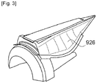
- the side panels are curved along their entire length, similar to panels 926 shown on figure 3 .
- the heat shield 28 of the APF forms a firewall between the engine and the engine pylon 6 then the wing 4. It is licked by the hot exhaust gases (primary flow) 30 which come out of the engine, while the side panels 26 of the APF are licked by a cooler secondary stream 32.
- FIGS. 3 to 6 show a prior art APF.
- a curved side panel 926 can be seen at the figure 3
- the figure 4 shows the parts of the APF framework which are normally hidden by the side panels, in particular the transverse reinforcing ribs 924.
- An APF according to the invention may have an identical or similar framework to that of known APFs, in particular ribs 924 such as those illustrated on the figures 3 and 4 .
- the panels of an APF according to the invention can be panels composed of flat plates or panels with a curved face such as panel 926 illustrated in figure 3 .
- the known APFs all have a monolithic metal heat shield 928, such as the one illustrated in figure 5 , while an APF according to the invention has a heat shield 28 with a multilayer structure.
- This multilayer heat shield can be flat or curved, single or double curved.
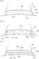
- the figures 6 to 12 show in more detail heat shields 28, 128, 228, 328, 428 and 528 with a multilayer structure according to the invention and the attachment thereof to the framework of the APF.
- the heat shield 28 of the APF (see fig. 6 ) comprises an insulating core 34, an outer skin 36 and an inner skin 38.
- the outer skin 36 and the inner skin 38 extend laterally beyond the insulating core 34, where they meet and are attached to each other. the other to form two longitudinal edges 40 which enclose the insulating core 34.
- These edges integrate a thermo-aerodynamic function having for objective to limit the rise of hot air coming from the primary flow and to improve the transition of the air flows between the hot air of the primary flow and the fresh air of the secondary flow.
- the core 34 of the heat shields shown on the figures 6 to 8 consists of a honeycomb honeycomb structure; another honeycomb structure, of any cross section in shape and surface, is of course possible.
- the figures 9 to 12 show other embodiments of the core of a heat shield with a multilayer structure according to the invention.
- Soul 234 of the shield of the figure 9 is made from a porous insulating material, such as a foam, chosen both for its thermal and acoustic properties, but also for its mechanical properties.
- a porous insulating material such as a foam
- the size of the porosities as well as the rate of porosity can take various values and in particular be adapted according to the acoustic, thermal and structural needs.
- the stiffness desired for the shield can determine the foam density chosen, depending on the stiffness of the inner skin 238 of the shield.
- the size and rate of porosities within the material may vary but will preferably be distributed evenly.
- foam will generically denote any porous material thus suitable for the invention.
- the insulating core 334 of the shield of the figure 10 comprises a central cellular block 334a of the alveolar structure type (eg honeycomb), the function of which is essentially to damp sound waves.
- the expression “honeycomb” will denote generically any acoustic cellular material suitable for the invention.
- the outer skin 336 of the shield is perforated with sound absorption holes facing said block 334a to allow sound waves to flow. enter the honeycomb.
- the sound absorption holes can vary from 0.1mm to 2.5mm in diameter. However, the holes will be as small as possible in order to limit their impact on the drag.
- these holes have a diameter of less than 0.8 mm, preferably less than 0.6 mm, or even less than 0.3 mm, for example of the order of 0.1 mm.
- the holes can have a cross section of any shape, for example circular, oblong, square, polygonal, teardrop-shaped, etc.
- the “diameter” of the holes then designates the largest transverse dimension of said holes.
- the Open Area Rate ratio between the total surface area of the holes over the total surface area of the skin facing the honeycomb
- the TSO may be between 3% and 25% depending on the need for acoustic attenuation and the required structural resistance.
- the insulating core 334 further comprises two lateral foam blocks 334b which participate in the thermal insulation (but little or no sound insulation) conferred by the shield and which also and above all have the function of stiffening the shield and of d '' reinforce its mechanical resistance.
- the insulating core 434 of the heat shield 428 of the figure 11 comprises a first cellular insulating layer 434a of the honeycomb structure type which forms, with the outer skin 436, quarter-wave resonators for damping the sound waves produced by the motor, and a second insulating layer 434b made of foam which contributes to the thermal insulation (the insulating core forming a thermal insulating blanket between the engine and the engine mast) and which also stiffens the shield.
- the foam of the 434b block may have or lack acoustic properties.
- the insulating thicknesses 434a and 434b extend over the entire width (or circumference) of the shield, with the exception of two longitudinal edges 440 (which enclose the insulating core); said insulating thicknesses are superimposed in a radial direction, that is to say in the direction of the thickness of the shield.
- the figure 12 shows another example of a heat shield 534 according to the invention combining two blocks of different cellular materials including a block 534a in honeycomb and a block 534b in foam.
- the acoustic function is essentially provided by the block 534a which is associated with a perforated resistive outer skin 536.
- the foam used for the block 534b can also exhibit acoustic properties and contribute to the attenuation of engine noise pollution, although its functions are mainly to improve the performance. mechanical resistance of the shield while contributing to thermal insulation.
- the two blocks 534a and 534b form two insulating layers superimposed in radial directions over a large majority of the width of the shield.
- the foam block 534b On each side of the shield, the foam block 534b further has a flange 535 which forms a lateral reinforcing strip between the honeycomb block 534a and a longitudinal edge 540 of the shield.
- the outer skin 536 is perforated only opposite the honeycomb block 534a and is solid opposite the lateral reinforcing bands 535 (in particular if the foam of the block 534b is not an "acoustic foam").
- the insulating cores illustrated are only non-limiting examples. All the combinations, superimpositions and assemblies of blocks of different insulating materials are possible according to the mechanical needs and according to the thermal and acoustic needs, according in particular to the geometry and the dimensions of the shield as well as the acoustic surface necessary to overcome an acoustic treatment. insufficient engine nacelle. It is also possible to provide an insulating core whose composition or properties vary in the longitudinal direction; for example, the insulating core contains a block of foam whose density varies in the longitudinal direction or it contains several blocks of different materials which follow one another in the longitudinal direction.
- the shields 128, 228, 328, 428 and 528 include longitudinal edges 140, 240, 340, 440, 540.
- the shield 28 of figures 6 and 7 further comprises two side mounting flanges 42 which each extend parallel to adjacent side panel 26 from inner skin 38 of the shield. These side flanges are used to assemble the shield and the APF frame. They can in fact be fixed to the side panels 26, against which they are pressed, by brazing, co-firing, welding or gluing or even using rivets or screws. Similarly, shields 228, 328, 428, 528 of figures 9 to 12 are fitted with side fixing brackets 242, 342, 442, 542.
- each rib 24 has, on each side of the APF, a lateral face which runs along the adjacent side panel 26.
- a shoulder is provided in the side face of the rib so that a space is created between the rib 24 and the side panel 26 on a lower portion of the rib.
- An upper portion of the shield mounting flange 42 fits into this space between the rib and the side panel.
- the figure 8 illustrates a variant in which the shield 128 is devoid of lateral fixing flanges.
- the internal skin 138 of the shield is pressed against a lower face of the ribs 124 of the framework and the internal skin 138 is fixed to said lower face of the ribs 124, for example by gluing or welding (the side panels 26 of the framework are in this case fixed to the ribs 124 after fixing the shield 128 to said ribs);
- the inner skin 138 is provided with fixing tabs (such as can be seen on the anterior monolithic shield of the figure 5 and each tab is fixed to a transverse face of a rib 124 using screws or by gluing or welding.
Landscapes
- Engineering & Computer Science (AREA)
- Chemical & Material Sciences (AREA)
- Combustion & Propulsion (AREA)
- Mechanical Engineering (AREA)
- Aviation & Aerospace Engineering (AREA)
- Ceramic Engineering (AREA)
- Laminated Bodies (AREA)
- General Engineering & Computer Science (AREA)
Applications Claiming Priority (1)
| Application Number | Priority Date | Filing Date | Title |
|---|---|---|---|
| FR1913646A FR3103787A1 (fr) | 2019-12-03 | 2019-12-03 | Carénage arrière de mât de moteur d’aéronef à bouclier thermique multicouche. |
Publications (2)
| Publication Number | Publication Date |
|---|---|
| EP3831719A1 true EP3831719A1 (de) | 2021-06-09 |
| EP3831719B1 EP3831719B1 (de) | 2022-02-16 |
Family
ID=69811138
Family Applications (1)
| Application Number | Title | Priority Date | Filing Date |
|---|---|---|---|
| EP20210751.2A Active EP3831719B1 (de) | 2019-12-03 | 2020-11-30 | Rückwärtige verkleidung einer motorsäule eines luftfahrzeugs mit mehrschichtigem wärmeschutzschild |
Country Status (3)
| Country | Link |
|---|---|
| US (1) | US20210163143A1 (de) |
| EP (1) | EP3831719B1 (de) |
| FR (1) | FR3103787A1 (de) |
Families Citing this family (2)
| Publication number | Priority date | Publication date | Assignee | Title |
|---|---|---|---|---|
| US12476509B2 (en) * | 2021-05-12 | 2025-11-18 | Vestas Wind Systems A/S | Preformed coil for an electric machine having a perforated insulating body and method of making same |
| US11970978B2 (en) * | 2021-06-25 | 2024-04-30 | Rohr, Inc. | Acoustic panel and method of forming same |
Citations (6)
| Publication number | Priority date | Publication date | Assignee | Title |
|---|---|---|---|---|
| EP2583900A2 (de) * | 2011-10-19 | 2013-04-24 | Airbus Operations (Société par actions simplifiée) | Aerodynamische Heckverkleidung für eine Triebwerksaufhängung, welche ein Hitzeschild umfasst, das sich frei ausdehnen kann |
| EP2644505A1 (de) | 2012-03-27 | 2013-10-02 | Airbus Operations (Société par actions simplifiée) | Aerodynamische Heckverkleidung mit verbesserter Temperaturresistenz für Ausleger einer Antriebseinheit eines Luftfahrzeugs |
| US20160368616A1 (en) * | 2015-06-22 | 2016-12-22 | Rohr, Inc. | Pylon with noise attenuating fairing |
| EP3219600A1 (de) * | 2016-03-14 | 2017-09-20 | The Boeing Company | Hitzeschildanordnung und -verfahren |
| FR3059300A1 (fr) * | 2016-11-30 | 2018-06-01 | Safran Nacelles | Carenage arriere de pylone de suspension du turboreacteur |
| FR3063068A1 (fr) * | 2017-02-23 | 2018-08-24 | Safran Nacelles | Carenage arriere de pylone en composite a matrice ceramique |
Family Cites Families (7)
| Publication number | Priority date | Publication date | Assignee | Title |
|---|---|---|---|---|
| US6983912B2 (en) * | 2002-04-30 | 2006-01-10 | The Boeing Company | Hybrid exhaust heat shield for pylon mounted gas turbine engines |
| FR2921342B1 (fr) * | 2007-09-20 | 2010-03-12 | Airbus France | Carenage aerodynamique arriere inferieur pour dispositif d'accrochage d'un moteur d'aeronef |
| US7943227B2 (en) * | 2007-10-11 | 2011-05-17 | The Boeing Company | Ceramic heat shield |
| FR2957894B1 (fr) * | 2010-03-23 | 2013-06-14 | Snecma | Pylone de support d'un turbomoteur recouvert d'un materiau poreux, ensemble d'un turbomoteur et d'un pylone |
| FR3072908B1 (fr) * | 2017-10-26 | 2021-02-26 | Safran Nacelles | Ensemble propulsif pour aeronef |
| US11359577B2 (en) * | 2018-08-22 | 2022-06-14 | Rohr, Inc. | Multi-degree of freedom acoustic panel |
| US11427298B2 (en) * | 2019-09-18 | 2022-08-30 | The Boeing Company | Advanced plume suppressing segmented heat shield |
-
2019
- 2019-12-03 FR FR1913646A patent/FR3103787A1/fr not_active Ceased
-
2020
- 2020-11-30 EP EP20210751.2A patent/EP3831719B1/de active Active
- 2020-12-01 US US17/109,021 patent/US20210163143A1/en not_active Abandoned
Patent Citations (6)
| Publication number | Priority date | Publication date | Assignee | Title |
|---|---|---|---|---|
| EP2583900A2 (de) * | 2011-10-19 | 2013-04-24 | Airbus Operations (Société par actions simplifiée) | Aerodynamische Heckverkleidung für eine Triebwerksaufhängung, welche ein Hitzeschild umfasst, das sich frei ausdehnen kann |
| EP2644505A1 (de) | 2012-03-27 | 2013-10-02 | Airbus Operations (Société par actions simplifiée) | Aerodynamische Heckverkleidung mit verbesserter Temperaturresistenz für Ausleger einer Antriebseinheit eines Luftfahrzeugs |
| US20160368616A1 (en) * | 2015-06-22 | 2016-12-22 | Rohr, Inc. | Pylon with noise attenuating fairing |
| EP3219600A1 (de) * | 2016-03-14 | 2017-09-20 | The Boeing Company | Hitzeschildanordnung und -verfahren |
| FR3059300A1 (fr) * | 2016-11-30 | 2018-06-01 | Safran Nacelles | Carenage arriere de pylone de suspension du turboreacteur |
| FR3063068A1 (fr) * | 2017-02-23 | 2018-08-24 | Safran Nacelles | Carenage arriere de pylone en composite a matrice ceramique |
Also Published As
| Publication number | Publication date |
|---|---|
| US20210163143A1 (en) | 2021-06-03 |
| FR3103787A1 (fr) | 2021-06-04 |
| EP3831719B1 (de) | 2022-02-16 |
Similar Documents
| Publication | Publication Date | Title |
|---|---|---|
| EP2321510B1 (de) | Lufteinlassstruktur einer Turboluftstrahltriebwerksgondel mit pneumatischem Frostschutzsystem | |
| EP2291840B1 (de) | Akustische platte für eine ausströmdüse | |
| CA2770257A1 (fr) | Ensemble structurant pour une tuyere d'ejection | |
| EP2318683A2 (de) | Schalldämpfungsplatte für luftfahrzeugmotorgondel | |
| CA2696204C (fr) | Fixation d'une structure d'une nacelle de turboreacteur par bride couteau/gorge renforcee | |
| WO2017021628A1 (fr) | Structure d'atténuation acoustique à multiples degrés d'atténuation pour ensemble propulsif d'aéronef | |
| WO2008113737A1 (fr) | Carenage aerodynamique arriere inferieur pour dispositif d' accrochage d' un moteur d' aeronef | |
| WO2009037267A1 (fr) | Carenage aerodynamique arriere inferieur pour dispositif d'accrochage d'un moteur d'aeronef | |
| WO2013024218A1 (fr) | Cône d'éjection pour turboréacteur d'aéronef | |
| EP3831719B1 (de) | Rückwärtige verkleidung einer motorsäule eines luftfahrzeugs mit mehrschichtigem wärmeschutzschild | |
| EP2454154B1 (de) | Nasenkantenstruktur, insbesondere für den lufteintritt einer flugzeugtriebwerksgondel | |
| EP3735378B1 (de) | Akustische behandlungsstruktur für die gondel eines triebwerks eines flugzeugs | |
| EP2599078A2 (de) | Akustikplatte für eine tl-triebwerksgondel mit integrierten befestigungselemente | |
| FR2956875A1 (fr) | Aube allegee pour turbomachine, carter comportant une pluralite d'une telle aube et turbomachine comportant au moins un tel carter | |
| WO2022117968A1 (fr) | Panneau multicellulaire d'attenuation acoustique a hauteur variable | |
| EP3483396A1 (de) | Leitschaufelring eines turboreaktors, der eine schalldämmstruktur umfasst | |
| EP4544166B1 (de) | Blockertür für eine schubumkehrvorrichtung eines flugzeugs | |
| FR2940360A1 (fr) | Panneau d'attenuation acoustique pour nacelle de moteur d'aeronef,structure d'entree d'air et structure interne fixe incorporant ledit panneau | |
| FR2940377A1 (fr) | Ensemble de pieces reliees entre elles par un dispositif permettant de conserver l'integrite de la surface de l'une des pieces | |
| FR3106334A1 (fr) | Panneau isolant multicouche à renforts de fixation intégrés et procédé de fabrication d’un tel panneau | |
| EP3853465B1 (de) | Akustisches management an einer turbomaschine oder einer gondel | |
| FR2960519A1 (fr) | Carenage aerodynamique de mat d'accrochage de moteur d'aeronef comprenant des raidisseurs ameliores | |
| WO2015001258A1 (fr) | Procédé de réparation d'un panneau par application d'un doubleur | |
| EP4562286A1 (de) | Flugzeugantriebsanordnung mit einer verbesserten verkleidungsplatte | |
| EP4413244A1 (de) | Akustisch behandelte luftdüse für eine gondel |
Legal Events
| Date | Code | Title | Description |
|---|---|---|---|
| PUAI | Public reference made under article 153(3) epc to a published international application that has entered the european phase |
Free format text: ORIGINAL CODE: 0009012 |
|
| STAA | Information on the status of an ep patent application or granted ep patent |
Free format text: STATUS: EXAMINATION IS IN PROGRESS |
|
| 17P | Request for examination filed |
Effective date: 20201130 |
|
| AK | Designated contracting states |
Kind code of ref document: A1 Designated state(s): AL AT BE BG CH CY CZ DE DK EE ES FI FR GB GR HR HU IE IS IT LI LT LU LV MC MK MT NL NO PL PT RO RS SE SI SK SM TR |
|
| GRAP | Despatch of communication of intention to grant a patent |
Free format text: ORIGINAL CODE: EPIDOSNIGR1 |
|
| STAA | Information on the status of an ep patent application or granted ep patent |
Free format text: STATUS: GRANT OF PATENT IS INTENDED |
|
| RIC1 | Information provided on ipc code assigned before grant |
Ipc: F02K 1/34 20060101ALI20210930BHEP Ipc: B64D 29/02 20060101AFI20210930BHEP |
|
| INTG | Intention to grant announced |
Effective date: 20211025 |
|
| GRAS | Grant fee paid |
Free format text: ORIGINAL CODE: EPIDOSNIGR3 |
|
| GRAA | (expected) grant |
Free format text: ORIGINAL CODE: 0009210 |
|
| STAA | Information on the status of an ep patent application or granted ep patent |
Free format text: STATUS: THE PATENT HAS BEEN GRANTED |
|
| RBV | Designated contracting states (corrected) |
Designated state(s): AL AT BE BG CH CY CZ DE DK EE ES FI FR GB GR HR HU IE IS IT LI LT LU LV MC MK MT NL NO PL PT RO RS SE SI SK SM TR |
|
| AK | Designated contracting states |
Kind code of ref document: B1 Designated state(s): AL AT BE BG CH CY CZ DE DK EE ES FI FR GB GR HR HU IE IS IT LI LT LU LV MC MK MT NL NO PL PT RO RS SE SI SK SM TR |
|
| REG | Reference to a national code |
Ref country code: GB Ref legal event code: FG4D Free format text: NOT ENGLISH |
|
| REG | Reference to a national code |
Ref country code: CH Ref legal event code: EP |
|
| REG | Reference to a national code |
Ref country code: DE Ref legal event code: R096 Ref document number: 602020001898 Country of ref document: DE |
|
| REG | Reference to a national code |
Ref country code: AT Ref legal event code: REF Ref document number: 1468733 Country of ref document: AT Kind code of ref document: T Effective date: 20220315 |
|
| REG | Reference to a national code |
Ref country code: IE Ref legal event code: FG4D Free format text: LANGUAGE OF EP DOCUMENT: FRENCH |
|
| REG | Reference to a national code |
Ref country code: LT Ref legal event code: MG9D |
|
| REG | Reference to a national code |
Ref country code: NL Ref legal event code: MP Effective date: 20220216 |
|
| REG | Reference to a national code |
Ref country code: AT Ref legal event code: MK05 Ref document number: 1468733 Country of ref document: AT Kind code of ref document: T Effective date: 20220216 |
|
| PG25 | Lapsed in a contracting state [announced via postgrant information from national office to epo] |
Ref country code: SE Free format text: LAPSE BECAUSE OF FAILURE TO SUBMIT A TRANSLATION OF THE DESCRIPTION OR TO PAY THE FEE WITHIN THE PRESCRIBED TIME-LIMIT Effective date: 20220216 Ref country code: RS Free format text: LAPSE BECAUSE OF FAILURE TO SUBMIT A TRANSLATION OF THE DESCRIPTION OR TO PAY THE FEE WITHIN THE PRESCRIBED TIME-LIMIT Effective date: 20220216 Ref country code: PT Free format text: LAPSE BECAUSE OF FAILURE TO SUBMIT A TRANSLATION OF THE DESCRIPTION OR TO PAY THE FEE WITHIN THE PRESCRIBED TIME-LIMIT Effective date: 20220616 Ref country code: NO Free format text: LAPSE BECAUSE OF FAILURE TO SUBMIT A TRANSLATION OF THE DESCRIPTION OR TO PAY THE FEE WITHIN THE PRESCRIBED TIME-LIMIT Effective date: 20220516 Ref country code: NL Free format text: LAPSE BECAUSE OF FAILURE TO SUBMIT A TRANSLATION OF THE DESCRIPTION OR TO PAY THE FEE WITHIN THE PRESCRIBED TIME-LIMIT Effective date: 20220216 Ref country code: LT Free format text: LAPSE BECAUSE OF FAILURE TO SUBMIT A TRANSLATION OF THE DESCRIPTION OR TO PAY THE FEE WITHIN THE PRESCRIBED TIME-LIMIT Effective date: 20220216 Ref country code: HR Free format text: LAPSE BECAUSE OF FAILURE TO SUBMIT A TRANSLATION OF THE DESCRIPTION OR TO PAY THE FEE WITHIN THE PRESCRIBED TIME-LIMIT Effective date: 20220216 Ref country code: ES Free format text: LAPSE BECAUSE OF FAILURE TO SUBMIT A TRANSLATION OF THE DESCRIPTION OR TO PAY THE FEE WITHIN THE PRESCRIBED TIME-LIMIT Effective date: 20220216 Ref country code: BG Free format text: LAPSE BECAUSE OF FAILURE TO SUBMIT A TRANSLATION OF THE DESCRIPTION OR TO PAY THE FEE WITHIN THE PRESCRIBED TIME-LIMIT Effective date: 20220516 |
|
| PG25 | Lapsed in a contracting state [announced via postgrant information from national office to epo] |
Ref country code: PL Free format text: LAPSE BECAUSE OF FAILURE TO SUBMIT A TRANSLATION OF THE DESCRIPTION OR TO PAY THE FEE WITHIN THE PRESCRIBED TIME-LIMIT Effective date: 20220216 Ref country code: LV Free format text: LAPSE BECAUSE OF FAILURE TO SUBMIT A TRANSLATION OF THE DESCRIPTION OR TO PAY THE FEE WITHIN THE PRESCRIBED TIME-LIMIT Effective date: 20220216 Ref country code: GR Free format text: LAPSE BECAUSE OF FAILURE TO SUBMIT A TRANSLATION OF THE DESCRIPTION OR TO PAY THE FEE WITHIN THE PRESCRIBED TIME-LIMIT Effective date: 20220517 Ref country code: FI Free format text: LAPSE BECAUSE OF FAILURE TO SUBMIT A TRANSLATION OF THE DESCRIPTION OR TO PAY THE FEE WITHIN THE PRESCRIBED TIME-LIMIT Effective date: 20220216 Ref country code: AT Free format text: LAPSE BECAUSE OF FAILURE TO SUBMIT A TRANSLATION OF THE DESCRIPTION OR TO PAY THE FEE WITHIN THE PRESCRIBED TIME-LIMIT Effective date: 20220216 |
|
| PG25 | Lapsed in a contracting state [announced via postgrant information from national office to epo] |
Ref country code: IS Free format text: LAPSE BECAUSE OF FAILURE TO SUBMIT A TRANSLATION OF THE DESCRIPTION OR TO PAY THE FEE WITHIN THE PRESCRIBED TIME-LIMIT Effective date: 20220617 |
|
| PG25 | Lapsed in a contracting state [announced via postgrant information from national office to epo] |
Ref country code: SM Free format text: LAPSE BECAUSE OF FAILURE TO SUBMIT A TRANSLATION OF THE DESCRIPTION OR TO PAY THE FEE WITHIN THE PRESCRIBED TIME-LIMIT Effective date: 20220216 Ref country code: SK Free format text: LAPSE BECAUSE OF FAILURE TO SUBMIT A TRANSLATION OF THE DESCRIPTION OR TO PAY THE FEE WITHIN THE PRESCRIBED TIME-LIMIT Effective date: 20220216 Ref country code: RO Free format text: LAPSE BECAUSE OF FAILURE TO SUBMIT A TRANSLATION OF THE DESCRIPTION OR TO PAY THE FEE WITHIN THE PRESCRIBED TIME-LIMIT Effective date: 20220216 Ref country code: EE Free format text: LAPSE BECAUSE OF FAILURE TO SUBMIT A TRANSLATION OF THE DESCRIPTION OR TO PAY THE FEE WITHIN THE PRESCRIBED TIME-LIMIT Effective date: 20220216 Ref country code: DK Free format text: LAPSE BECAUSE OF FAILURE TO SUBMIT A TRANSLATION OF THE DESCRIPTION OR TO PAY THE FEE WITHIN THE PRESCRIBED TIME-LIMIT Effective date: 20220216 Ref country code: CZ Free format text: LAPSE BECAUSE OF FAILURE TO SUBMIT A TRANSLATION OF THE DESCRIPTION OR TO PAY THE FEE WITHIN THE PRESCRIBED TIME-LIMIT Effective date: 20220216 |
|
| REG | Reference to a national code |
Ref country code: DE Ref legal event code: R097 Ref document number: 602020001898 Country of ref document: DE |
|
| PG25 | Lapsed in a contracting state [announced via postgrant information from national office to epo] |
Ref country code: AL Free format text: LAPSE BECAUSE OF FAILURE TO SUBMIT A TRANSLATION OF THE DESCRIPTION OR TO PAY THE FEE WITHIN THE PRESCRIBED TIME-LIMIT Effective date: 20220216 |
|
| PLBE | No opposition filed within time limit |
Free format text: ORIGINAL CODE: 0009261 |
|
| STAA | Information on the status of an ep patent application or granted ep patent |
Free format text: STATUS: NO OPPOSITION FILED WITHIN TIME LIMIT |
|
| 26N | No opposition filed |
Effective date: 20221117 |
|
| PG25 | Lapsed in a contracting state [announced via postgrant information from national office to epo] |
Ref country code: MC Free format text: LAPSE BECAUSE OF FAILURE TO SUBMIT A TRANSLATION OF THE DESCRIPTION OR TO PAY THE FEE WITHIN THE PRESCRIBED TIME-LIMIT Effective date: 20220216 |
|
| REG | Reference to a national code |
Ref country code: BE Ref legal event code: MM Effective date: 20221130 |
|
| PG25 | Lapsed in a contracting state [announced via postgrant information from national office to epo] |
Ref country code: IT Free format text: LAPSE BECAUSE OF FAILURE TO SUBMIT A TRANSLATION OF THE DESCRIPTION OR TO PAY THE FEE WITHIN THE PRESCRIBED TIME-LIMIT Effective date: 20220216 |
|
| PG25 | Lapsed in a contracting state [announced via postgrant information from national office to epo] |
Ref country code: LU Free format text: LAPSE BECAUSE OF NON-PAYMENT OF DUE FEES Effective date: 20221130 |
|
| PG25 | Lapsed in a contracting state [announced via postgrant information from national office to epo] |
Ref country code: IE Free format text: LAPSE BECAUSE OF NON-PAYMENT OF DUE FEES Effective date: 20221130 |
|
| PG25 | Lapsed in a contracting state [announced via postgrant information from national office to epo] |
Ref country code: BE Free format text: LAPSE BECAUSE OF NON-PAYMENT OF DUE FEES Effective date: 20221130 |
|
| PG25 | Lapsed in a contracting state [announced via postgrant information from national office to epo] |
Ref country code: CY Free format text: LAPSE BECAUSE OF FAILURE TO SUBMIT A TRANSLATION OF THE DESCRIPTION OR TO PAY THE FEE WITHIN THE PRESCRIBED TIME-LIMIT Effective date: 20220216 |
|
| PG25 | Lapsed in a contracting state [announced via postgrant information from national office to epo] |
Ref country code: MK Free format text: LAPSE BECAUSE OF FAILURE TO SUBMIT A TRANSLATION OF THE DESCRIPTION OR TO PAY THE FEE WITHIN THE PRESCRIBED TIME-LIMIT Effective date: 20220216 |
|
| REG | Reference to a national code |
Ref country code: CH Ref legal event code: PL |
|
| PG25 | Lapsed in a contracting state [announced via postgrant information from national office to epo] |
Ref country code: CH Free format text: LAPSE BECAUSE OF NON-PAYMENT OF DUE FEES Effective date: 20231130 |
|
| PG25 | Lapsed in a contracting state [announced via postgrant information from national office to epo] |
Ref country code: CH Free format text: LAPSE BECAUSE OF NON-PAYMENT OF DUE FEES Effective date: 20231130 |
|
| PG25 | Lapsed in a contracting state [announced via postgrant information from national office to epo] |
Ref country code: MT Free format text: LAPSE BECAUSE OF FAILURE TO SUBMIT A TRANSLATION OF THE DESCRIPTION OR TO PAY THE FEE WITHIN THE PRESCRIBED TIME-LIMIT Effective date: 20220216 |
|
| PG25 | Lapsed in a contracting state [announced via postgrant information from national office to epo] |
Ref country code: HU Free format text: LAPSE BECAUSE OF FAILURE TO SUBMIT A TRANSLATION OF THE DESCRIPTION OR TO PAY THE FEE WITHIN THE PRESCRIBED TIME-LIMIT; INVALID AB INITIO Effective date: 20201130 |
|
| PG25 | Lapsed in a contracting state [announced via postgrant information from national office to epo] |
Ref country code: TR Free format text: LAPSE BECAUSE OF FAILURE TO SUBMIT A TRANSLATION OF THE DESCRIPTION OR TO PAY THE FEE WITHIN THE PRESCRIBED TIME-LIMIT Effective date: 20220216 |
|
| PGFP | Annual fee paid to national office [announced via postgrant information from national office to epo] |
Ref country code: DE Payment date: 20251119 Year of fee payment: 6 |
|
| PGFP | Annual fee paid to national office [announced via postgrant information from national office to epo] |
Ref country code: GB Payment date: 20251121 Year of fee payment: 6 |
|
| PGFP | Annual fee paid to national office [announced via postgrant information from national office to epo] |
Ref country code: FR Payment date: 20251126 Year of fee payment: 6 |
|
| PG25 | Lapsed in a contracting state [announced via postgrant information from national office to epo] |
Ref country code: SI Free format text: LAPSE BECAUSE OF FAILURE TO SUBMIT A TRANSLATION OF THE DESCRIPTION OR TO PAY THE FEE WITHIN THE PRESCRIBED TIME-LIMIT Effective date: 20220216 |