EP3831723A2 - Ensemble de transport panplanétaire et procédé pour mettre des charges utiles en orbite circulaire - Google Patents
Ensemble de transport panplanétaire et procédé pour mettre des charges utiles en orbite circulaire Download PDFInfo
- Publication number
- EP3831723A2 EP3831723A2 EP19843080.3A EP19843080A EP3831723A2 EP 3831723 A2 EP3831723 A2 EP 3831723A2 EP 19843080 A EP19843080 A EP 19843080A EP 3831723 A2 EP3831723 A2 EP 3831723A2
- Authority
- EP
- European Patent Office
- Prior art keywords
- linear
- planet
- general planetary
- launch
- bearing structure
- Prior art date
- Legal status (The legal status is an assumption and is not a legal conclusion. Google has not performed a legal analysis and makes no representation as to the accuracy of the status listed.)
- Granted
Links
Images









Classifications
-
- B—PERFORMING OPERATIONS; TRANSPORTING
- B64—AIRCRAFT; AVIATION; COSMONAUTICS
- B64G—COSMONAUTICS; VEHICLES OR EQUIPMENT THEREFOR
- B64G99/00—Subject matter not provided for in other groups of this subclass
-
- B—PERFORMING OPERATIONS; TRANSPORTING
- B64—AIRCRAFT; AVIATION; COSMONAUTICS
- B64G—COSMONAUTICS; VEHICLES OR EQUIPMENT THEREFOR
- B64G1/00—Cosmonautic vehicles
- B64G1/002—Launch systems
-
- B—PERFORMING OPERATIONS; TRANSPORTING
- B64—AIRCRAFT; AVIATION; COSMONAUTICS
- B64G—COSMONAUTICS; VEHICLES OR EQUIPMENT THEREFOR
- B64G1/00—Cosmonautic vehicles
- B64G1/10—Artificial satellites; Systems of such satellites; Interplanetary vehicles
-
- B—PERFORMING OPERATIONS; TRANSPORTING
- B64—AIRCRAFT; AVIATION; COSMONAUTICS
- B64G—COSMONAUTICS; VEHICLES OR EQUIPMENT THEREFOR
- B64G1/00—Cosmonautic vehicles
- B64G1/10—Artificial satellites; Systems of such satellites; Interplanetary vehicles
- B64G1/1085—Swarms and constellations
-
- B—PERFORMING OPERATIONS; TRANSPORTING
- B64—AIRCRAFT; AVIATION; COSMONAUTICS
- B64G—COSMONAUTICS; VEHICLES OR EQUIPMENT THEREFOR
- B64G1/00—Cosmonautic vehicles
- B64G1/14—Space shuttles
-
- B—PERFORMING OPERATIONS; TRANSPORTING
- B64—AIRCRAFT; AVIATION; COSMONAUTICS
- B64G—COSMONAUTICS; VEHICLES OR EQUIPMENT THEREFOR
- B64G1/00—Cosmonautic vehicles
- B64G1/22—Parts of, or equipment specially adapted for fitting in or to, cosmonautic vehicles
- B64G1/40—Arrangements or adaptations of propulsion systems
- B64G1/411—Electric propulsion
- B64G1/417—Electromagnetic fields or flux without mass expulsion
-
- B—PERFORMING OPERATIONS; TRANSPORTING
- B64—AIRCRAFT; AVIATION; COSMONAUTICS
- B64G—COSMONAUTICS; VEHICLES OR EQUIPMENT THEREFOR
- B64G1/00—Cosmonautic vehicles
- B64G1/22—Parts of, or equipment specially adapted for fitting in or to, cosmonautic vehicles
- B64G1/42—Arrangements or adaptations of power supply systems
- B64G1/425—Power storage
- B64G1/426—Flywheels
-
- B—PERFORMING OPERATIONS; TRANSPORTING
- B64—AIRCRAFT; AVIATION; COSMONAUTICS
- B64G—COSMONAUTICS; VEHICLES OR EQUIPMENT THEREFOR
- B64G5/00—Ground equipment for vehicles, e.g. starting towers, fuelling arrangements
-
- B—PERFORMING OPERATIONS; TRANSPORTING
- B64—AIRCRAFT; AVIATION; COSMONAUTICS
- B64G—COSMONAUTICS; VEHICLES OR EQUIPMENT THEREFOR
- B64G1/00—Cosmonautic vehicles
- B64G1/10—Artificial satellites; Systems of such satellites; Interplanetary vehicles
- B64G1/12—Artificial satellites; Systems of such satellites; Interplanetary vehicles manned
Definitions
- the invention relates to the area of space science and space transportation, in particular, to the area of commercial exploitation of outer space, and, namely - to the structure of multiple-mission geospatial transportation complex and method of operation thereof, based on the principle of non-rocket planet surface to the planned circular orbit payload insertion.
- Its intended purpose of use is to solve the set of geospatial problems in industrial-scale volumes, for instance, for the purpose of relocation of ecologically harmful portion of earth-based manufacturing into near space and non-rocket space industrialization, as well as - stabilization of global climate and carrying out of R&D, special-purpose, touristic and other types of works and services in outer space.
- K.E. Tsiolkovsky the pioneer of cosmonautics
- K.E. Tsiolkovsky who was first to lay theoretical foundation for manned spaceflight, elaborated and justified rocket reaction principle. He highlighted the need to search for and create alternative methods and equipment to launch humans into space and set up extraterrestrial orbital space stations, as intermediate (support) bases in development of interplanetary communications and colonization in the form of human settlements in space.
- K.E. Tsiolkovsky presents a profound assessment of the number of systems of possible transportation space structures developed by him, including Space Elevator, Equatorial Tower and Equatorial Circular Train [1].
- the structure has been also known as proposed by Yu. Artsutanov' cosmic (space) elevator as method for delivery of cargos to geostationary orbit [2].
- space space
- cosmic elevator with the overall viability of such approach to the issue of replacement of jet rocket thrust during payload insertion into circumplanetary orbit, has a sufficiently high unit cost of its delivery, with the required extremely high strength of materials of the self-bearing elevator cable, length around 40 thousand km, which are capable to withstand dead load and load due to massive counterweight.
- Space Fountain The system of such space vehicle, named Space Fountain, is known: a structure for delivering cargos to orbit.
- Space Fountain is an alternative to space elevator, and as compared to the design thereof, Space Fountain is an extremely tall hollow tower with its cavity filled with special granular substance. This substance, after transferring kinetic energy to it, moves rapidly up from the base of the tower and transfers this energy to the top thereof, after which it falls back to the base of the tower under the influence of gravity.
- Cargos along the Space Fountain can be lifted in two ways: with the assistance of special systems like elevator in buildings, or with the stream of granules (pellets) [3].
- Space Fountain can be built near the planet's surface.
- the tower will be capable of lifting all the payload needed for its own construction.
- Space Fountain can be built and will function successfully even on celestial bodies with very low gravity, such as the Moon, Mercury.
- Space Fountain is active-use structure and therefore requires constant consumption of significant amount of energy to maintain its existence and can only lift cargo via assigned altitude rather than put payload into circular orbit at the first cosmic velocity.
- Slingatron of Tidman [4] is known.
- Slingatron - space slingshot - features the same principle working as in a traditional slingshot.
- Slingatron is based on a large spiral tube, inside which acceleration of a small capsule with microsatellite happens.
- the spiral tube is fixed on system of rotating levers with counterweights that drive powerful electric motors.
- a space vehicle such as Space Gun is also known, a method of launching an object into outer space with a huge gun, of a shooting or electromagnetic type, is also known. It refers to rocket-free methods of placing objects into orbit [5].
- Lofstrom loop There is a less well-known project to bring an object into outer space, which functions in the same way as space elevator, but does not need materials ahead of the modern state of the art. It's called Lofstrom loop. The construction of this loop is based on a conductive cord closed in a ring and drawn to a huge length inside a vacuum tube. To prevent contact of cord with tube walls, it is suspended therein by means of magnetic levitation [6].
- the cargo In order to launch the cargo into space, it is lifted to altitude of about 80 km and installed at one of ends of a multi-kilometer portion of the loop running parallel to Earth. Magnetic fields created by the acceleration unit interact with the magnetic field in the conductor and, due to the occurring eddy currents, accelerate the cargo until it has gained the required orbital velocity. After that, with the help of a small rocket engine, the cargo is separated from Lofstrom loop and enters the required orbit.
- the Space Bridge is also known for its design of rocket-free space transportation systems.
- SB is the design of astroengineering installation for non-rocket method of inserting cargo into planetary orbit with the use of ring which becomes weightless by rotation around the planet's equator.
- SB represents a huge trestle (overpass) made in the form of an annular body with an endless flywheel belt placed therein with the feasibility of moving at space velocities, shrouding the Earth along the equator.
- Part of the trestle lies on the surface of the planet, and the other part extends into space. Along the trestle the cargo is taken into and back from space.
- Earth-Moon Complex [8] is known, which comprises Earth-space lift and Earth-Moon module.
- Earth-space lift is made in form of retractable cylindrical sections having screws with hoops (collars) stabilizing vertical lift and mounted vertically in ground in reinforced concrete housing.
- the housing also has tanks filled with liquefied natural gas with high-pressure chambers supplying high pressure of gases and steam to the lower part of lifting cylinders.
- Earth-Moon module has cylindrical shape and is equipped with technical compartments, cargo elevator with lifting shock-absorbing pillar and movable supports.
- a disadvantage of such a method of putting payloads into Earth orbit is the unacceptable threat of destruction of the planet's protective ozone layer and the unpredictability of the results of the electric discharge interaction of the plasma whirl with the Earth's ionosphere.
- a model of orbital station [10] comprising mockup of annular orbital station, which encircles the planet and is made in the form of an extensible toroid-shape shell, with which solenoids are fastened to, electrically connected to power source and interacting with a toroidal movable core of variable perimeter.
- a general planetary vehicle by Yunitski [11] which represents a circular toroid-shape bearing structure, ringing around the planet and its center of mass, and comprising a vacuum sealed hollow body with axisymmetrically located inside thereof, at least two flywheels in the form of endless belts, and with electromagnetic suspension systems contactlessly mounted thereon on; equipped with electromagnetic drives connected through control system and a communication system of electric energy with power supply source; whereby the hollow body of flywheels is arranged inside the shell aligned therewith, also coaxially positioned within the female outer casing, the casing being assembled into a continuous chain of rigid units, performed with feasibility of mutual longitudinal movement, whereas space free of rigid units is used to form transportation compartments, whereby that said casing is furnished with locks to be secured- detached on launch overpass supports arranged along planet perimeter along the equator.
- Yunitski which comprises general planetary vehicle encircling the planet along the line of the planet surface cross-section by the plane parallel to plane of the equator, fastened, according to the first variant (embodiment) of the claimed invention, on launch overpass of altitude h, m, defined by the ratio: 10 ⁇ 7 ⁇ h / R ⁇ 10 ⁇ 4 , where R, m, - radius of planet in plane of arranging launch overpass, and representing a linear bearing structure encircling the planet and having length L 0 , m, comprising pressure hull with at least two vacuum channels, ringing around the planet, in the first one of which the first endless planet-encircling linear flywheel is located, and in the second one - the second endless planet-encircling linear flywheel is located, whereas the first linear flywheel and the second linear flywheel are contactlessly positioned in relation to the walls of the corresponding vacuum channels and equipped
- the specified result is achieved also thanks to the general planetary geospatial transportation complex by Yunitski, which includes general planetary vehicle encircling the planet along the line of the planet surface cross-section by the plane parallel to plane of the equator, fastened, according to the second variant (embodiment) of the claimed invention, in liquid ocean at launch depth h v , m, defined by the ratio: 10 ⁇ 7 ⁇ h v / R v ⁇ 10 ⁇ 4 , where R v , m, - radius of planet in plane of arranging general planetary vehicle in liquid ocean, and representing a linear bearing structure encircling the planet and having length L 0 , m, comprising pressure hull with at least two vacuum channels, ringing around the planet, in the first one of which the first endless planet-encircling linear flywheel is located, and in the second one - the second endless planet-encircling linear flywheel is located, whereas the first linear flywheel and the second linear flywheel are contactlessly positioned in relation to
- transportation compartments may be embodied both inside the body of linear bearing structure, or fastened outside thereupon.
- General planetary geospatial transportation complex by Yunitski may be embodied in such way that linear bearing structure of general planetary vehicle is made from elastically deformable material with modulus of elasticity E, Pa, within the following range: 10 8 ⁇ E ⁇ 5 ⁇ 10 11
- General planetary geospatial transportation complex by Yunitski may be embodied in such way that linear bearing structure is embodied as telescopically interconnected units.
- General planetary geospatial transportation complex by Yunitski may be embodied in such way that linear bearing structure is embodied as units interconnected by bellows.
- General planetary geospatial transportation complex by Yunitski may be embodied in such way that launch density ⁇ 1v , kg/m 3 , of general planetary vehicle is secured by pontoon means, responsible for fastening linear bearing structure in liquid of ocean at depth h v , m.
- General planetary geospatial transportation complex by Yunitski may be embodied in such way that launch density ⁇ 1l , kg/m 3 , of general planetary vehicle is secured by balloons, responsible for fastening linear bearing structure in gaseous environment at altitude h l , m.
- the general planetary geospatial transportation complex by Yunitski is equipped by fixing locks of linear bearing structure at launch altitude h, m, or h v , m, or h l , m, respectively in elevated structure (overpass), in liquid of ocean or in gaseous environment of planet, along the entire length L 0 , m, thereof.
- linear force N 1 , N/m, of acceleration and/or deceleration of linear flywheels is applied uniformly along entire length thereof via linear electromagnetic drives.
- linear force N 1 , N/m of their acceleration and/or deceleration, is regulated with regard to the rated value of that linear force N 0 , N/m, within the range determined by the ratio: 0,9 ⁇ N 1 / N 0 ⁇ 1,1
- Attaining the given task is secured by the fact that, as part of payload, in the amount of 0,1-10% of its mass m 3 , kg, liquid and/or gaseous ballast uniformly loaded along the entire length L 0 , m, of linear bearing structure, is used.
- ballast ecologically friendly to planet Earth substances and materials are used: water and/or compressed, and/or liquid air and/or oxygen, and/or nitrogen.
- Additional subject of the present invention is use of ballast during lifting (ascent) of general planetary vehicle, according to technical solution according to any of claims 11, 12 and 13, onto circular orbit of altitude H, m, to restore the ozone hole, improve weather and stabilize climate on Earth as a result of its spraying in planetary atmosphere.
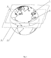
- the claimed general planetary geospatial transportation complex by Yunitski comprises general planetary vehicle 5 encircling the planet 1 along the line 2 of the planet 1 surface cross-section by the plane 3 parallel to plane 4 of the equator 4.1, fastened, according to the first variant (embodiment) of the claimed invention, on launch overpass 6 of altitude h, m, defined by the ratio: 10 ⁇ 7 ⁇ h / R ⁇ 10 ⁇ 4 , where R, m, - radius of planet 1 in plane 3 of arranging launch overpass 6.
- specific launch overpass 6 can be constructed according to any existing technologies of building overpasses, for example, manufactured according to SkyWay technology, which is based on use, as bearing structure, of continuous prestressed track structure, positioned along the equator 4.1.
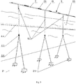
- Altitude of launch overpass 6 depending on relief varies from several meters to several hundred meters and may include (see Fig.7 ) columns - supports 6.1, connected to each other by span structures 6.2 with network passages 6.3 located therein, made, for example, in the form of transport vacuum channels.
- launch overpass 6 may represent an annular (circular) support bearing structure, also comprising columns - supports 6.1 fixed at certain depth with use of floating support 6.4, embodied, e.g., as vacuum tube, and equipped, for example, with counterweights 6.5 of columns - supports 6.1, with tension cables 6.6.
- Optimal altitude h, m, of launch overpass 6 is the value determined by the ratio (1). Under these conditions, the costs of manufacturing, maintenance and operation of general planetary vehicle 5 are minimized.
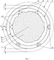
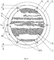
- general planetary vehicle 5 represents a linear bearing structure 7 of length L 0 , m, encircling planet 1, comprising pressure hull 8 with at least two vacuum channels 9, respectively, 9.1 and 9.2, also encircling planet 1, with encircling planet 1 endless linear flywheels 10, respectively, 10.1 and 10.2, positioned therein.
- first linear flywheel 10.1 is arranged in first vacuum channel 9.1
- second linear flywheel 10.2 is arranged in second vacuum channel 9.2.
- linear flywheel 10 is meant a seizing planet 1 giant annular closed rim in the form of open torus rotatably mounted around the joint with planet 1 center of mass.
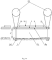
- Linear flywheel 10 may be realized in various technical embodiments, for instance, as closed multilayer endless belt 10.3, which represents a kind of rotor of linear electromagnetic motor with linear electromagnetic drive (see Fig. 18 ). Thereby, its separate belts, jointly shaping up closed multilayer endless belt 10.3, will be configured for possibility of elastic elongation under stretching force or corresponding displacement of the layers of endless belt 10.3 with respect to each other.
- Both linear flywheels 10.1 and 10.2 are contactlessly positioned in relation to walls of the relevant vacuum channel 9.1 or 9.2, and equipped with the systems of magnetic and/or electromagnetic suspension 11, respectively 11.1 and 11.2, and linear electromagnetic drives 12, accordingly, 12.1 and 12.2.
- systems of magnetic and/or electromagnetic suspension 11 and linear electromagnetic drives 12 are configured to accelerate linear flywheels 10 up to velocity V 0 , m/sec, determined by the ratio: 1,1 ⁇ V 0 / V eh ⁇ 5 , where V eh , m/sec, - first cosmic velocity at altitude h, m.
- Acceleration of at least one of linear flywheels 10 up to velocity V 0 , m/sec, determined from ratio (2), makes it possible to achieve, at minimum required energy consumption, balancing of attraction force from planet towards general planetary vehicle 5 and its subsequent launch into space with lifting to planned circular orbit 13 of altitude H, m, and reaching of first cosmic (circumferential around planet 1) velocity V 1H , m/sec, by pressure hull 8 of linear bearing structure 7 of general planetary vehicle 5 at planned circular orbit 13 of altitude H, m.
- the optimum velocity V 0 , m/sec, of acceleration of at least one of linear flywheels 10 to provide accumulation of kinetic energy and the launch amount (angular momentum) of motion sufficient to launch general planetary vehicle 5 and ensure it enters space into planned circular orbit 13 with payload 14 (see Fig.6 ) reaching first cosmic velocity V 1H , m/sec, is a value determined by the ratio (2). Under the specified limits, energy costs necessary to ensure the operability of general planetary vehicle 5 are minimized.
- Linear bearing structure 7 is equipped with transportation compartments 15, both built-in - 15.1, and detachable (mounted) - 15.2 (see Figs.5 - 8 ) and embodied with possibility of extension without loss of continuity, defined by the ratio: 1,01 ⁇ L H / L 0 ⁇ 1,25 , where L H , m, - length of linear bearing structure 7 on planned circular orbit 13 of altitude H, m.
- the range of elastic extension of linear bearing structure 7 without loss of continuity indicated in the ratio (3) is due to the range of change in length L 0 , m of linear bearing structure 7 in launch state and length L H , m, of this linear bearing structure 7 on planned circular orbit 13 of altitude H, M .
- linear flywheels 10 respectively, 10.1 and 10.2 have corresponding masses m 1 and m 2 , kg, defined from the ratio: 0,1 ⁇ m 1 / m 2 ⁇ 10 ,
- Embodiment of linear flywheels 10.1 and 10.2 with corresponding masses m 1 m 2 , kg, specified in the ratio (4), is conditioned by the modes of realization of processes of launch into space and return landing on planet 1 of general planetary vehicle 5 with use of launch kinetic energy accumulated therein and launch amount (angular momentum) of motion.
- Embodiment of linear flywheels 10.1 and 10.2 with masses m 1 and m 2 , kg, ratio of which is less than 0.1 or more than 10, leads either to reduction in efficiency of general-planet vehicle 5 as a whole, or to significant and impractical increase of velocity (rotation) of at least one of linear flywheels at the moment of launch of general planetary vehicle 5 from planet 1, which causes considerable complication and increase of cost of realization of the entire project on transportation complex. In addition, this will lead to additional losses of significant portion of energy when it is switched from one flywheel, which is slowed, with its drive is operating in generator mode, to another flywheel, which at this time accelerates in counter-direction.
- Systems 11 of magnetic and/or electromagnetic suspension and drives 12 of linear flywheels 10 along their entire length L 0 are connected to linear power supply source 16, embodied, for example, in the form of linear (running along linear bearing structure 7) power supply system, capable of including a variety of possible combinations of generating power systems available on planet 1, through control system 17 and power communication system 18 (see Fig. 15 ).
- General planetary vehicle 5 is also equipped with fixing locks 19 for fastening linear bearing structure 7 to the launch overpass 6 along the entire length L 0 , m, which automatically operate and release linear bearing structure 7 at the moment of its launch from planet 1 and fix the position of linear bearing structure 7 of general planetary vehicle 5 in the initial position when it returns to planet 1 (see Figs.7 - 9 ).
- the claimed general planetary geospatial transportation complex by Yunitski includes general planetary vehicle 5 encircling the planet 1 along the line 2 of the planet 1 surface cross-section by the plane 3 parallel to plane 4 of the equator 4.1, fastened, according to the second variant (embodiment) of the claimed invention, (See Figs.3 and 10 ), by fixing locks 19 located in liquid 20 of ocean of planet 1 at launch depth h v , m, defined by the ratio: 10 ⁇ 7 ⁇ h v / R v ⁇ 10 ⁇ 4 , where R v , m, - radius of planet 1 in plane 3 of arranging general planetary vehicle 5 in liquid 20 of ocean of planet 1.
- Optimal value of launch depth h v , m, of immersion of general planetary vehicle 5 into liquid 20 of planet 1 ocean is the value determined by the ratio (5). Under these conditions, the manufacturing, maintenance and operation costs of general planetary vehicle 5 are minimized and buoyancy of liquid 20 is maximized.
- general planetary vehicle 5 is, in this case, represents a linear bearing structure 7 of length L 0 , m, encircling the planet 1, comprising pressure hull 8 with at least two vacuum channels 9, respectively, 9.1 and 9.2, also encircling planet 1, with endless linear flywheels 10 fastened therein.
- first linear flywheel 10.1 is arranged in first vacuum channel 9.1
- second linear flywheel 10.2 is arranged in second vacuum channel 9.2.
- linear flywheel 10 as in the first embodiment of the invention, is meant a seizing planet 1 giant annular closed rim in the form of open torus rotatably mounted around the joint with planet 1 center of mass.
- Both linear flywheels 10.1 and 10.2 are contactlessly positioned in relation to walls of the relevant vacuum channel 9.1 or 9.2, and equipped with the systems of magnetic and/or electromagnetic suspension 11, respectively 11.1 and 11.2, and linear electromagnetic drives 12, accordingly, 12.1 and 12.2, of first and second linear flywheels 10.1 and 10.2, respectively (see Fig.5 and Fig.6 ).
- systems of magnetic and/or electromagnetic suspension 11 and linear electromagnetic drives 12 are configured to accelerate linear flywheels 10 up to velocity V 0 , m/sec, determined by the ratio: 1,1 ⁇ V 0 / V vh ⁇ 5 , where V vh , m/sec, - first cosmic velocity at launch depth h v , m.
- the optimum velocity V 0 , m/sec, of acceleration of at least one of linear flywheels 10 to provide accumulation of kinetic energy and the launch amount (angular momentum) of motion sufficient to launch general planetary vehicle 5 and ensure it enters space into planned circular orbit 13 from thickness of liquid 20 of ocean of planet 1, is a value determined by the ratio (6). Under the specified limits, energy costs necessary to ensure the operability of general planetary vehicle 5 are minimized.
- Linear bearing structure 7 similar to the first embodiment of the invention, is also provided (see Fig.5 , Fig.6 and Fig. 10 ) with transportation compartments 15 and configured to be extended without losing its continuity as determined from the ratio (3): 1,01 ⁇ L H / L 0 ⁇ 1,25 .
- Substantiation of the range of elastic extension of linear bearing structure 7 without loss of continuity indicated in the ratio (3) is similar to the justification of this range given as such for the first embodiment and due to the range of change of length L 0 , m, of linear bearing structure 7 in launch state at launch depth h v , m, and length L H , m, of this linear bearing structure 7 on planned circular orbit 13 of altitude H, M .
- linear flywheels 10 respectively, 10.1 and 10.2, by analogy with justification of the choice of value of their masses m 1 and m 2 , kg, specified in the first variant of embodiment of general planetary vehicle 5, have the corresponding masses m 1 and m 2 , kg, defined by the ratio (4): 0,1 ⁇ m 1 / m 2 ⁇ 10
- Embodiment of linear flywheels 10.1 and 10.2 with masses m 1 and m 2 , kg, ratio of which is less than 0.1 or more than 10, leads either to reduction of efficiency of general planetary vehicle 5, or to significant and impractical increase of velocity (rotation) of at least one of linear flywheels at the moment of launch of general planetary vehicle 5 from planet 1, which leads to considerable complication and increase of cost of realization of the entire project on transportation complex.
- general planetary vehicle 5 is embodied with launch density ⁇ 1v , kg/m 3 , defined by the ratio: 0,5 ⁇ ⁇ 2 / ⁇ 1 v ⁇ 2 , where ⁇ 2 , kg/m 3 , - density of liquid 20 of ocean of planet 1 at launch depth h v , m.
- launch density ⁇ 1v , kg/m 3 , of general planetary vehicle 5 should be understood to mean the mass of the structure in unit volume of general planetary vehicle 5 in its prelaunch state at launch depth h v , m, in liquid 20 of ocean of planet 1.
- Embodiment of general planetary vehicle 5 with launch density ⁇ 1v , kg/m 3 , indicated in the ratio (7), is due to optimization of technology for construction and maintenance of general planetary vehicle 5 while ensuring its location in liquid 20 at assigned launch depth h v , m, in global ocean.
- Optimum launch density ⁇ 1v , kg/m 3 , for the second embodiment of general planetary vehicle 5 is the value determined by the ratio (7). Under these conditions, the costs of manufacturing, maintenance and operation of general planetary vehicle are minimized 5.
- drives 12 of linear flywheels 10 are also connected to power supply source 16 through control system 17 and power communication system 18 (see Fig. 15 ) and organized in a manner similar to that described in the first embodiment of the invention for operation and realization of the respective systems of general planetary geospatial transportation complex.
- general planetary geospatial transportation complex by Yunitski is also equipped with fixing locks 19 (see Fig. 10 ) for fastening of linear bearing structure 7 in liquid 20 of ocean, for example, to floating supports 6.4, and/or to anchors 21.1, arranged at bed 21 of ocean along their entire length L 0 , m.
- Anchors 21.2 mounted on hard surface of planet 1 may be also used to secure linear bearing structure 7 in liquid 20 of ocean, such as in channels and/or along straits.
- tension cables 6.6, connecting anchors 21.2 with locks 19, extend from anchors 21.2 from surface of planet 1 under surface of liquid 20 of ocean.
- Locks 19 automatically operate and release linear bearing structure 7 at the moment of its launch from planet 1 and fix position of linear bearing structure 7 of general planetary vehicle 5 in initial position at its return to planet 1. Thanks to presence of locks 19 for fastening of linear bearing structure 7, it is possible, due to acceleration to velocity of V 0 , m/sec, of at least one of linear flywheels 11, to accumulate energy necessary and sufficient for lifting of general planetary vehicle 5 to planned circular orbit 13 of altitude H, m.
- launch density ⁇ 1v , kg/m 3 , of general planetary vehicle 5 was secured with pontoon means 22 connected with fixing locks 19 of linear bearing structure 7 installed all over its length L 0 , m, and which are fastened in liquid 20 of ocean and/or at its bed 21 by anchors 21.1 (see Figures 3 and 10 ) and responsible for prelaunch arrangement of general planetary vehicle 5 in liquid 20 of ocean at launch depth h v , m.
- pontoon means 22 to compensate launch density ⁇ 1v , kg/m 3 , of general planetary vehicle 5 up to design limits indicated in the ratio (7) makes it possible to simplify its design and increase its technological effectiveness and efficiency (see Fig.3 and Fig.10 ).
- the proposed general planetary geospatial transportation complex of Yunitski includes general planetary vehicle 5, covering planet 1 along the line 2 of surface section of planet 1 by the plane 3 parallel to the plane 4 of the equator 4.1, fixed, according to the third variant of the invention (see Figs.4 and 11 ), in gaseous environment 23 of atmosphere of planet 1 at launch altitude h l , m, determined by the ratio: 10 ⁇ 7 ⁇ h l / R l ⁇ 10 ⁇ 2 , where R l , m, - radius of planet 1 in plane 3 of arranging general planetary vehicle 5 in gaseous environment 23 of atmosphere of planet 1.
- Positioning of general planetary vehicle 5 in gaseous environment 23 of atmosphere of planet 1 at launch altitude h l , m indicated in the ratio (8), is due to optimization of technology of construction and maintenance of general planetary vehicle 5 at its "atmospheric" launch.
- Optimal value of launch altitude h l , m, of lifting general planetary vehicle 5 above surface of planet 1 is the value determined by the ratio (8). Under these conditions, the costs of manufacturing, maintenance and operation of general planetary vehicle 5 are minimized.
- general planetary vehicle 5 is, in this case, represents a linear bearing structure 7 of length L 0 , m, encircling the planet 1, comprising pressure hull 8 with at least two vacuum channels 9, respectively, 9.1 and 9.2, also encircling planet 1, with endless linear flywheels 10 placed therein.
- first linear flywheel 10.1 is arranged in first vacuum channel 9.1
- second linear flywheel 10.2 is arranged in second vacuum channel 9.2.
- linear flywheel 10 as in the first two embodiments of the invention, is meant a seizing planet 1 giant annular closed rim in the form of open torus rotatably mounted around the center of mass of planet 1.
- Both linear flywheels 10.1 and 10.2 are contactlessly positioned in relation to walls of the relevant vacuum channel 9.1 or 9.2, and equipped with the systems of magnetic and/or electromagnetic suspension 11, respectively 11.1 and 11.2, and linear electromagnetic drives 12, accordingly, 12.1 and 12.2, of first and second linear flywheels 10.1 and 10.2, respectively (see Fig.5 and Fig.6 ).
- systems of magnetic and/or electromagnetic suspension 11 and linear electromagnetic drives 12 are configured to accelerate linear flywheels 10 up to velocity V 0 , m/sec, determined by the ratio: 1,1 ⁇ V 0 / V lh ⁇ 5 , where V lh , m/sec, - first cosmic velocity at launch altitude h l , m.
- the optimum velocity V 0 , m/sec, of acceleration of at least one of linear flywheels 10 to provide accumulation of kinetic energy and the amount (angular momentum) of motion sufficient to launch general planetary vehicle 5 and ensure it enters space into planned circular orbit 13 from gaseous environment 23 of atmosphere of planet 1, is a value determined by the ratio (9). Under the specified limits, energy costs necessary to ensure the operability of general planetary vehicle 5 are minimized.
- linear bearing structure 7 similar to the first two embodiments of the invention, is provided with transportation compartments 15 (see Fig.7 and 8 ) and can be extended without losing its continuity as determined from the ratio (3): 1,01 ⁇ L H / L 0 ⁇ 1,25
- Substantiation of the range of elastic extension of linear bearing structure 7 without loss of continuity indicated in the ratio (3) is similar to the justification of this range given as such for the first two embodiments of the installation and due to the range of change of length L 0 , m, of linear bearing structure 7 in launch state (see Fig.4 ) at launch altitude h l , m, and length L H , m, of this linear bearing structure 7 on planned circular orbit 13 of altitude H, M.
- linear flywheels 10 respectively, 10.1 and 10.2, by analogy with justification of the choice of value of their masses m 1 and m 2 , kg, specified in the first two variants of embodiment of general planetary vehicle 5, have the corresponding masses m 1 and m 2 , kg, defined by the ratio (4): 0,1 ⁇ m 1 / m 2 ⁇ 10
- Embodiment of linear flywheels 10.1 and 10.2 with masses m 1 and m 2 , kg, ratio of which is less than 0.1 or more than 10, leads either to reduction of efficiency of general planetary vehicle 5, or to significant and impractical increase of velocity (rotation) of at least one of linear flywheels at the moment of launch of general planetary vehicle 5 from planet 1, which leads to considerable complication and increase of cost of realization of the entire project on transportation complex.
- general planetary vehicle 5 is embodied with launch density ⁇ 1l , kg/m 3 , determined by the ratio: 0,1 ⁇ ⁇ 3 / ⁇ 1 l ⁇ 2 , where ⁇ 3 , kg/m 3 , - density of gaseous environment 23 of atmosphere of planet 1 at launch altitude h l , M .
- density ⁇ 3 , kg/m 3 , of atmosphere of any planet 1, containing the atmosphere as on the Earth, will drop as the launch altitude increases h l , m, and under launch density ⁇ 1l , kg/m 3 , of general planetary vehicle 5, in this case, should be understood the mass of structure in unit volume of general planetary vehicle 5, at its prelaunch state at launch altitude h l , m, in gaseous environment 23 of atmosphere of planet 1.
- the optimum launch density ⁇ 1l , kg/m 3 , for the third embodiment of general planetary vehicle 5, is value determined by the ratio (10). Under these conditions, the costs of manufacturing, maintenance and operation of general planetary vehicle 5 are minimized.
- drives 12 of linear flywheels 10 are also connected to power supply source 16 through control system 17 and power communication system 18 (see Fig. 15 ) and organized in a manner similar to that described in these embodiments of the invention for operation and realization of the respective systems of general planetary geospatial transportation complex.
- general planetary geospatial transportation complex by Yunitski Similar to the first two variants of the invention, general planetary geospatial transportation complex by Yunitski according to third variant, also equipped by fixing locks 19 (see Fig. 11 ) for fastening linear bearing structure 7 along the entire length L 0 , m, in liquid 20 of ocean to special floating supports 6.4, or to anchors 21.1 placed on ocean bed 21 and/or to hard surface of planet 1 on anchors 21.2 placed thereupon. Locks 19 automatically operate and release linear bearing structure 7 at the moment of its launch from planet 1 and/or fix position of linear bearing structure 7 of general planetary vehicle 5 in initial position at its return to planet 1.
- launch density, ⁇ 1v , kg/m 3 , of general planetary vehicle 5 was secured, for example, with balloons 24, connected to fixing locks 19 of linear bearing structure 7 and fixed, for example, in gaseous environment 23 of atmosphere of planet 1, and/or in liquid 20 of ocean, and/or on hard surface of planet 1, respectively, on balloons 24, floating supports 6.4 and/or anchors 21.1, and/or anchors 21.2 along its entire length L 0 , m, of linear bearing structure 7 and performing pre-launch positioning of general planetary vehicle 5 in gaseous environment 23 of atmosphere of planet 1 at launch altitude h l , M.
- balloons 24 to compensate launch density ⁇ 1l , kg/m 3 , of general planetary vehicle 5 to design limitations, specified in the ratio (10) will simplify its design and increase its technological efficiency and efficiency (see Fig.11 ).
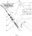
- transportation compartments 15 may be placed both inside pressure hull 8 of linear bearing structure 7, or fastened outside thereupon, correspondingly, those are built-in transportation compartments 15.1 and detachable transportation compartments 15.2 (see Fig.5 - 8 , Fig.10 , 11 and 14 ).
- outside detachable transportation compartments 15.2 will allow to increase efficiency and lower costs of their maintenance on stages of loading and unloading of general planetary vehicle 5.
- linear ballast system 25 As structure of linear ballast system 25, a portion of interconnected along the entire length L 0 , m, transportation compartments 15 of linear bearing structure 7 of general planetary vehicle 5, can be used.
- Equipping of general planetary vehicle 5 with linear ballast system 25, covering the planet 1 and uniformly loaded along its entire length with liquid and/or gaseous ballast 26, provides balancing of the whole structure and excludes its vibrations at operation during motion of general planetary vehicle 5 from launch moment to rise to planned circular orbit 13 of altitude H, m.
- linear bearing structure 7 of general planetary vehicle 5 is made elastically of elastically deformable material with modulus of elasticity E, Pa, within the following range: 10 8 ⁇ E ⁇ 5 ⁇ 10 11
- the range of the modulus of elasticity E, Pa is selected on the basis of strength conditions stipulated by design assignment and the possibility of providing elastic deformation of pressure hull 8 of linear bearing structure 7 without loss of continuity within the range of change of length L 0 , m, of linear bearing structure 7 from launch state up to its length L H , m, on planned circular orbit 13 of altitude H, M.
- Embodiment of linear bearing structure 7 and, accordingly, of general planetary vehicle 5 as a whole, from materials with values of modulus of elasticity E, Pa, less than 10 8 does not allow to ensure their required strength and rigidity.
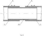
- general planetary geospatial transportation complex by Yunitski can be realized in such a way that pressure hull 8 of linear bearing structure 7 of general planetary vehicle 5 is embodied in the form of units 27 joined to each other by telescopic connections 28 (see Fig. 19 ).
- Embodiment of pressure hull 8 of linear bearing structure 7 of general planetary vehicle 5 in the form of units 27 integrated with each other along the length of telescopic connections 28 allows to reduce power consumption required to provide elastic deformation in longitudinal direction of structural members of general planetary vehicle 5 and expand the range of materials used for manufacture thereof.
- general planetary geospatial transportation complex by Yunitski can be realized in such a way that pressure hull 8 of linear bearing structure 7 of general planetary vehicle 5 is embodied in the form of units 27 interconnected with each other by bellows 29 (see Fig.20 ).
- bellows 29 as structural members for interconnecting units 27 of general planetary vehicle 5 also leads to reduction in power consumption, required to ensure linear elastic deformation of structure of pressure hull 8 of general planetary vehicle 5 during its lifting to planned circular orbit 13 of altitude H, m, and increases reliability and durability of the structure as a whole while simplifying it.
- General planetary vehicle 5 is a self-supporting aircraft made in the form of a torus with cross section of up to a few meters, encircling the planet 1 in a plane 3 parallel to the plane of the equator 4. It can exit into space, overcoming the attraction of planet 1, using only the internal forces of the system, without any energetic, mechanical, chemical and other types of environmentally harmful interaction with the environment, that is, it will be extremely environmentally friendly.
- each linear member of general planetary vehicle 5 must have first cosmic velocity V 1H , m/sec, on planned circular orbit 13 at altitude H, m.
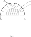
- linear flywheels 10.1 and/or 10.2 Prior to launch of general planetary vehicle 5, linear flywheels 10.1 and/or 10.2 should have sufficient initial kinetic energy and launch amount (kinetic momentum) of motion to provide (see Fig. 16 ) a centrifugal force P , N, capable of lifting general planetary vehicle 5 of mass m 0 , kg, to planned circular orbit 13, taking into account all energy losses occurring in this case:
- the kinetic energy K, J, of at least one of linear flywheels 10 required to lift general planetary vehicle 5 to planned circular orbit 13 of altitude H, m is determined by the dependence: where , kg, - weight of at least one of linear flywheels 10; r p , m, - current orbit radius of at least one of linear flywheels 10; ⁇ , rps, - angular velocity of at least one of linear flywheels 10; m 0 , kg, - mass of general planetary vehicle 5; ⁇ p , m/sec, - radial velocity of general planetary vehicle 5; and it must be greater than the attractive force to the center of planet 1, the elastic force acting on the members of linear bearing structure 7 during lifting of general planetary vehicle 5 and the resistance force of gaseous environment 23 of atmosphere of planet 1 (see Fig.
- Q k f ⁇ 0 r ⁇ p 2 exp ⁇ ⁇ n r p / R e ⁇ 1
- G, H - attractive force of planet 1 (e.g., Earth); g, m/sec 2 , - gravitational acceleration at the equator; R e , m, - radius of the equator of the planet 1;
- general planetary vehicle 5 is held along its entire length L 0 , m, on launch overpass 6 of altitude h, m, and/or in liquid 20 of ocean at launch depth h v , m, and/or in gaseous environment 23 of planetary 1 atmosphere at launch altitude h l , m, by means of fixing locks 19 of linear bearing structure 7 in the corresponding initial launch position (see Fig.8 , Fig. 10 and Fig.11 );
- Third - payload 14 of total mass m 3 , kg, including ballast 26, is placed uniformly along the entire length L 0 , m, of linear bearing structure 7 in transportation compartments 15;
- Ballast 26 performs several important functions for operation of general planetary vehicle 5.
- At least one linear flywheel 10 is accelerated in the co-rotational direction regarding the planet 1 to velocity V 0 , m/sec, exceeding first cosmic velocity V eh , m/sec, at altitude h, m, of launch overpass 6, and/or V vh , m/sec, - first cosmic velocity in liquid of ocean at launch depth h v , m, and/or V lh , m/sec, - first cosmic velocity in gaseous environment of planetary atmosphere at launch altitude h l , m, by at least 10%.
- At least one of linear flywheels 10 is accelerated along the corresponding vacuum channel 9, wherein that linear flywheel 10 does not experience motion resistance and is rotated around the planet 1 with an axis of rotation passing through the center of mass of planet 1.
- at least one of linear flywheels 10 accumulates the required amount of kinetic energy K, J, the pulse (angular momentum) which is necessary for general planetary vehicle 5 to reach planned circular orbit 13 at a given orbital velocity V 1H , m/sec.
- the charging time of general planetary vehicle 5 is not limited to the necessary energy even under the condition of low power of linear electromagnetic drive 12.
- Efficiency of linear electromagnetic drives 12 of general planetary vehicle 5 is not less than 95%, that is, it will be about one hundred times higher than that of rocket (missile) (taking into account pre-launch and launch costs and energy losses, including for obtaining rocket fuel), energy efficiency of modern rocket carriers is less than 1%. Therefore, with the same drive capacity as heavy launch vehicle (about 100 million kilowatts), it will be possible to take into space not just tens of tons, but millions of tons of payload 14 per flight.
- linear bearing structure 7 of general planetary vehicle 5 is guaranteed to attain circumferential velocity around planet 1 in co-rotational direction re planet 1, equal to first cosmic velocity V 1H , m/sec, on planned circular orbit of altitude H, M, above planet surface, by decelerating the first linear flywheel 10.1 and transmitting, respectively, according to law of conservation of angular momentum in closed system, the motion pulse from linear flywheel 10 of linear bearing structure 7 of general planetary vehicle 5, whereas energy generated during deceleration of the first linear flywheel 10.1 - for acceleration in counter-direction of the second linear flywheel 10.2;
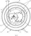
- linear electromagnetic drives 12 of both linear flywheels 10 are turned off in planned circular orbit 13 of altitude H, m, above surface of planet 1, and general planetary vehicle 5 is unloaded, for example, into orbital circular (seizing the planet) complex 30 (see Fig.14 );
- launch of classic interplanar rocket-type satellite (not shown in the figures), fixed on the outer part of pressure hull 8 of linear bearing structure 7 similar to transportation compartments 15.2, can be carried out from general planetary vehicle 5 inserted on planned circular orbit 13 of altitude H, m, above the surface of planet 1.
- general planetary vehicle 5 is returned to the initial launch position by lowering the altitude of linear bearing structure 7 of general planetary vehicle 5 from planned circular orbit 13 of altitude H, m, above the surface of planet 1 to h, m, or h v , m, or h l , m, respectively, on launch overpass 6, in liquid 20 of ocean or in gaseous environment 23 of planetary 1 atmosphere, by decelerating one of linear flywheels 10 and accelerating the other linear flywheel 10 in opposite direction until linear bearing structure 7 has a zero circumferential velocity relative to planet 1.
- Modes of smooth acceleration and/or deceleration of linear flywheels 10 are secured thanks to action of adjustable linear force N 0 , N/m, thereon, coming from all uniformly distributed over the entire length L 0 , m, of linear bearing structure 7 of general planetary vehicle 5 of subsystems of the system of linear electromagnetic drives 12, as well as by maintaining the standard operation of subsystems of the system of magnetic and/or electromagnetic suspension 11, respectively, together with the system of linear electromagnetic drives 12.
- Operation of linear electromagnetic drives 12, in turn, is controlled and coordinated by control system 17 connected with them by means of communication system 18 equipped with feedback and technical parameters monitoring subsystems (see Fig. 15 ).
- Control of motion of linear flywheels 10 and coordination of value of linear force N 1 , N/m, acting on each individual section thereof, are performed so that all members of linear bearing structure 7 of general planetary vehicle 5 move uniformly, excluding occurrence of longitudinal vibrations and other possible disturbances in motion of members of its structure.
- linear force N 1 , N/m their acceleration and/or deceleration are adjusted relative to the nominal value of that linear force N 0 , N/m, within the boundaries, determined from the ratio: 0,9 ⁇ N 1 / N 0 ⁇ 1,1
- Range of ratio of linear force N 1 , N/m, of acceleration and/or deceleration of linear flywheels 10 to nominal value of that linear force N 0 , N/m, is selected on the basis of conditions of operation reliability of general planetary vehicle 5, stipulated by the design assignment, and possibility of achieving of the required velocity, including launch velocity, of linear flywheels 10 without possible disturbances in motion of members of general planetary vehicle 5.
- the payload 14 (passengers and cargoes), at least one of linear flywheels 10 of general planetary vehicle 5, - which has operational weight, e.g., 40 million tons (and, accordingly, specific weight - approximately 1000 kg/m), - should accumulate kinetic energy in the amount of 1,25 ⁇ 10 18 J (around 3,5 ⁇ 10 11 kW ⁇ h).
- the initial energy reserves should be at least by 10% more, that is, will be around 1,4 ⁇ 10 18 J (3,9 ⁇ 10 11 kW ⁇ h).
- each of its linear meters begins to move from the center of rotation of linear flywheels 10, that is, to rise vertically upwards in plane of the equator passing through the center of mass of the Earth.
- the ring (circle) of general planetary vehicle 5 will increase in diameter symmetrically in all directions relative to the center, and its body - elongate, stretch, without any displacement of the center of mass of this giant ring, which, according to law of conservation, will always coincide, in this case, with the center of mass of the planet Earth.
- the acceleration of climbing into space depends on excessive centrifugal forces. For example, if lifting force acting on each linear meter of general planetary vehicle 5 is bigger than the weight of each linear meter thereof by 5%, general planetary vehicle 5 will start to climb up with a comfortable acceleration of 0.5 m/sec 2 , or equal to 5% of gravitational acceleration. When moving with this acceleration, general planetary vehicle 5 will rise (expand in plane of the Earth's equator) to altitude of 100 km in 5 minutes 16 seconds and will have a vertical lift velocity at this altitude of 570 km/h.
- the hull of general planetary vehicle 5 should extend by 1.57%. Accordingly, the diameter of pressure hull 8 of general planetary vehicle 5 will also increase by 1.57%, which is easily achievable by structural and technological solutions such as telescopic connections 28 along the length of the rigid units 27 of linear bearing structure 7 of general planetary vehicle 5, or by uniting them with each other by means of bellows 29 (spring tabs) and other proven techniques known from the art.
- structural and technological solutions such as telescopic connections 28 along the length of the rigid units 27 of linear bearing structure 7 of general planetary vehicle 5, or by uniting them with each other by means of bellows 29 (spring tabs) and other proven techniques known from the art.
- the braking (generator) mode is activated on linear electromagnetic drive 12.1 of the first linear flywheel 10.1, accelerated at the surface of the Earth to cosmic velocity V 0 , m/sec, in co-rotational direction of planet 1.
- the generated power is transmitted by means of control system 17 and communication system 18 to acceleration of the second linear flywheel 10.2 in the counter-direction in relation to the first linear flywheel 10.1.
- general planetary vehicle 5 receives a double pulse and begins to rotate towards the rotation of the Earth.
- acceleration of rotation is the same comfortable 0.5 m/sec 2 , general planetary vehicle 5, and the entire payload 14 located therein (or thereon), will gain an estimated orbital, i.e. circular, velocity, for example, of 7671 m/sec (for an altitude of 400 km) after 4 hours.
- an estimated orbital i.e. circular, velocity, for example, of 7671 m/sec (for an altitude of 400 km) after 4 hours.
- the climbing and orbital velocity modes are selected so that general planetary vehicle 5 at a given altitude has an appropriate orbital velocity and is in equilibrium and its vertical (radial) velocity is zero.
- a special ballast system 25 is used in the process of entering space, if necessary.
- liquid and/or gaseous ballast 26 is used, uniformly arranged along the whole length L 0 , m, of linear bearing structure 7.
- ballast 26 reserve of less than 0.1% of mass of payload 14 a significant increase in the velocity of rotation of linear flywheels 10 at launch is required in order to improve stabilization of general planetary vehicle 5 when it is lifted into space (to use the gyroscopic effect), resulting in unduly high energy costs and additional structural difficulties.
- ballast 26 reserve exceeding 10% of payload 14' mass, the share of payload 14 placed by linear bearing structure 7 of general planetary vehicle 5 into circular orbit 13 of altitude H, m, above the surface of planet 1, is significantly reduced, which leads to penalized efficiency of operation of the whole complex.
- ballast 26 during lifting will be about 10-100 kilograms per linear meter of general planetary vehicle 5 (for the above cited input data).
- ballast 26 ecologically friendly to Planet Earth substances and materials are used: water and/or compressed, and/or liquid air and/or oxygen, and/or nitrogen.
- ballast 26 is sprayed in a predetermined amount in the ozone layer of planet 1 and above (altitudes from 10 to 60 km), it will be possible to regulate the oxygen and ozone content in the upper atmosphere and to "heal" the ozone holes, as well as ecologically safely manage the weather and climate on planet Earth.
- ballast 26 when lifting general planetary vehicle 5 into planned circular orbit 13 of altitude H, m to restore the ozone layer, improve weather and stabilize the climate on Earth by spraying the it in the atmosphere of planet 1, which is also a new essential feature corresponding to the inventive step.
- the payload 14 is unloaded, for example, into the orbital circular (seizing the planet) complex 30 (see Fig.19 ).
- the load-carrying capacity of the described variant of general planetary vehicle 5 is 250 kg/m under Earth conditions, or 10 million tons of payload 14.
- the cost of geospatial transportation by general planetary vehicle 5 along the routes Earth-Orbit and Orbit-Earth consists of three main components:
- linear flywheels 10 can rotate inside vacuum channels 9 for years, as the magnetic cushion of the magnetic and/or electromagnetic suspension system 11, like the vacuum of vacuum channels 9, will not create resistance when they travel at space velocities.
- the length of the equatorial complex of launch overpass 6 of general planetary vehicle 5 will be 40,076 km, of which about 20% will be for land sections and 80% for sea sections.
- Launch overpass 6 of general planetary vehicle 5, located along the equator 4.1, will represent transport and infrastructure communicator. Power transmission lines and communication lines will also be integrated into launch overpass 6 (not shown).
- the cost of the support and communication part based on launch overpass 6 located along the equator 4.1 can be estimated at 1.320 billion USD, provided that, on average, it will cost 25 million USD/km on land sections and 35 million USD/km - on sea sections.
- depreciation charges per 1 ton of cargo from capital investments in transport and communication part at the equatorial basing of launch overpass 6 will amount to:
- stages Development of general planetary geospatial transportation complex in conditions of planet Earth includes the following basic directions (stages):
- the launch overpass 6 may be an annular (circular) support bearing structure, also comprising columns - supports 6.1 with locks 19 fixed at a certain depth in liquid 20 of ocean with use of floating support 6.4, fastened by anchors 21.1 on ocean bed 21, connected to counterweights 6.5 of columns - supports 6.1, for example, by means of tension cables 6.6.
- the launch process of general planetary vehicle 5 proceeds as follows.
- a traveling magnetic field is generated.
- vacuum channel 9 located in pressure hull 8 of general planetary vehicle 5, there is a linear flywheel 10 having a magnetic and/or electromagnetic suspension 11 and being a kind of rotor of linear electromagnetic motor.
- a current is induced that will interact with the magnetic field which generated it, and linear flywheel 10, which does not experience any resistance (it is placed in vacuum), will come into motion (see Fig.8 ). More precisely, in rotation around the Earth.
- linear flywheel 10 will become weightless.
- centrifugal force, through magnetic and/or electromagnetic suspension 11 will exert ever-increasing effect on pressure hull 8 of general planetary vehicle 5, that is vertical lifting force, until each of its linear meters is counterweighted.
- the payload 14 (loads and passengers) is placed into general planetary vehicle 5 being held on launch overpass 6, with the first linear flywheel 10.1 having specific weight of 2 tons per meter, pre-rotated to velocity of 16 km/s, and exactly the same, but quiescent, the second linear flywheel 10.2.
- the payload 14 is preferably placed on general planetary vehicle 5 prior to the start of linear flywheel 10.
- the payload 14 is placed both inside and outside pressure hull 8 of general planetary vehicle 5, but so that the load as a whole is evenly distributed along the length of the L 0 , m, of linear bearing structure 7. After release of the locks 19 (see Figs.
- ballast 26 ecologically friendly to Planet Earth substances and materials are used: water or pre-liquefied air, oxygen or nitrogen.
- the tension of pressure hull 8 of general planetary vehicle 5, as its diameter increases, will be relatively small: its length under Earth conditions will increase by 1.57% per each 100 kilometers of lifting. Elongation of pressure hull 8 is compensated by moving its rigid units 27 relative to each other, the ends of which, for example, telescopically fit into each other and are interconnected, for example, by hydraulic cylinders (not shown on figures).
- Linear flywheel 10, for example, in the form of a closed multilayer endless belt, which represents a kind of rotor of linear electromagnetic motor, will be extended by elastic stretching or slight displacement of the layers of the forming belt with respect to each other (see Fig. 18 ).
- the lifting velocity of general planetary vehicle 5 at any section of the track can be set within wide limits, from pedestrian speed to aircraft velocity.
- General planetary vehicle 5 passes through atmospheric section at minimum possible radial velocities.
- linear electromagnetic drive 12.1 of the first linear flywheel 10.1 After leaving the dense atmosphere, the reversible mode of linear electromagnetic drive 12.1 of the first linear flywheel 10.1 is switched on to generator mode. Linear flywheel 10.1 will start to brake and linear electromagnetic drive 12.1 will generate electric current. This energy is transmitted through control system 17 and communication system 18 to linear electromagnetic drive 12.2 of the second linear flywheel 10.2, which is accelerated in counter direction to the movement of the first linear flywheel 10.1 (see Fig. 7 and 15 ).
- the second linear flywheel 10.2 having, for example, same mass as the first linear flywheel 10.1, previously stationary with respect to pressure hull 8 of linear bearing structure 7 of general planetary vehicle 5, starts to rotate in reverse direction relative to the first linear flywheel 10.1.
- This ensures the law of energy conservation, in the process of insertion of payload 14 from surface of planet 1 into planned circular orbit 13 and stability of kinetic energy of members of general planetary vehicle 5 rotating around planet 1.
- Pressure hull 8 of general planetary vehicle 5 and everything inside therein, and all that is attached to it from the outside - linear electromagnetic drives 12 with linear flywheels 10, as well as detachable transportation compartments 15.2 with payload 14 and the like - subject to law of conservation of angular momentum of the system, will come into rotation. It will start rotating in the same direction as the first linear flywheel 10.1 until it reaches a circumferential velocity equal to the first cosmic velocity. Radial velocity of general planetary vehicle 5 will fall to zero.
- the payload 14 (cargo and passengers), delivered to destination, is unloaded, for example, into orbital circular (seizing the planet) complex 30 located at altitude H, m, of planned circular orbit 13 of planet 1 (see Fig. 13 and 14 ).
- Landing of general planetary vehicle 5 on Earth is performed in reverse order.
- General planetary vehicle 5 will consume the initial kinetic energy reserve, which from the first linear flywheel 10.1, during launch of general planetary vehicle 5, will be redistributed to its pressure hull 8, and upon return to the planet 1, will be redistributed again between linear flywheels 10.1 and 10.2, for example, partially transmitted to at least the second linear flywheel 10.2.
- space cargo energy will be added, - payload 14, delivered from space to Earth. For example, delivering a ton of cargo from the Moon will produce the same amount of energy as a ton of oil (the lunar cargo with respect to Earth has kinetic and potential energy which are utilized by general planetary vehicle 5 and converted into electrical form).
- general planetary vehicle 5 On the way to space and back, general planetary vehicle 5 will receive such amount of cheap energy that will satisfy both its own needs and a large part of the energy needs of civilization as a whole.
- energy sources suitable for use by the proposed general planetary geospatial transportation complex: solar energy obtained, for example, through solar panels, which can be fixed on the pressure hull 8; ionosphere currents and the Earth's rotational energy around its axis (not shown).
- the energy thus obtained by general planetary vehicle 5 will be either accumulated in its linear flywheels 10 or transferred to planet Earth.
- the method and variants of embodiment of the invention are optimized and ensure the industrialization of near space in the foreseeable future with the aim of taking the environmentally dirty earth-based manufacturing industry outside the biosphere.
Landscapes
- Engineering & Computer Science (AREA)
- Remote Sensing (AREA)
- Aviation & Aerospace Engineering (AREA)
- Combustion & Propulsion (AREA)
- Physics & Mathematics (AREA)
- Chemical & Material Sciences (AREA)
- Astronomy & Astrophysics (AREA)
- General Physics & Mathematics (AREA)
- Electromagnetism (AREA)
- Magnetic Bearings And Hydrostatic Bearings (AREA)
- Non-Mechanical Conveyors (AREA)
- Other Liquid Machine Or Engine Such As Wave Power Use (AREA)
- Connection Of Motors, Electrical Generators, Mechanical Devices, And The Like (AREA)
- Fittings On The Vehicle Exterior For Carrying Loads, And Devices For Holding Or Mounting Articles (AREA)
- Radar, Positioning & Navigation (AREA)
Applications Claiming Priority (2)
| Application Number | Priority Date | Filing Date | Title |
|---|---|---|---|
| EA201800525A EA201800525A1 (ru) | 2018-08-01 | 2018-08-01 | Общепланетарный геокосмический транспортный комплекс юницкого (варианты) и способ выведения полезной нагрузки с поверхности планеты на круговую орбиту |
| PCT/BY2019/000014 WO2020024035A2 (fr) | 2018-08-01 | 2019-09-27 | Ensemble de transport géocosmique panplanétaire (et variantes) et procédé pour mettre des charges utiles en orbite circulaire depuis la surface d'une planète |
Publications (4)
| Publication Number | Publication Date |
|---|---|
| EP3831723A2 true EP3831723A2 (fr) | 2021-06-09 |
| EP3831723A4 EP3831723A4 (fr) | 2022-03-16 |
| EP3831723B1 EP3831723B1 (fr) | 2023-09-27 |
| EP3831723C0 EP3831723C0 (fr) | 2023-09-27 |
Family
ID=69230918
Family Applications (1)
| Application Number | Title | Priority Date | Filing Date |
|---|---|---|---|
| EP19843080.3A Active EP3831723B1 (fr) | 2018-08-01 | 2019-09-27 | Ensemble de transport panplanétaire et procédé pour mettre des charges utiles en orbite circulaire |
Country Status (5)
| Country | Link |
|---|---|
| US (1) | US20220055778A1 (fr) |
| EP (1) | EP3831723B1 (fr) |
| CN (1) | CN113195362B (fr) |
| EA (1) | EA201800525A1 (fr) |
| WO (1) | WO2020024035A2 (fr) |
Families Citing this family (4)
| Publication number | Priority date | Publication date | Assignee | Title |
|---|---|---|---|---|
| CN111477065B (zh) * | 2020-04-08 | 2022-11-04 | 杭州幻行科技有限公司 | 基于磁悬浮的加速度的动感模拟器 |
| EA202000304A1 (ru) * | 2020-08-11 | 2022-02-28 | Анатолий Эдуардович Юницкий | Искусственный орбитальный кольцевой комплекс юницкого и способ его реализации |
| CN113844681A (zh) * | 2021-09-01 | 2021-12-28 | 中国化学工程第三建设有限公司 | 一种磁悬浮真空管道运载系统 |
| CN118514872B (zh) * | 2024-07-19 | 2024-10-11 | 沈阳微控飞轮技术股份有限公司 | 卫星发射装置 |
Family Cites Families (30)
| Publication number | Priority date | Publication date | Assignee | Title |
|---|---|---|---|---|
| US4075948A (en) * | 1974-01-31 | 1978-02-28 | Minovitch Michael Andrew | Rapid transit system |
| US4318517A (en) * | 1977-07-20 | 1982-03-09 | Salkeld Robert J | Closed space structures |
| SU1165417A1 (ru) * | 1980-12-26 | 1985-07-07 | Taran Valentin M | Модель космической станции |
| US4795113A (en) * | 1984-02-06 | 1989-01-03 | Minovitch Michael Andrew | Electromagnetic transportation system for manned space travel |
| US4730797A (en) * | 1985-08-12 | 1988-03-15 | Minovitch Michael Andrew | Inflatable core orbital construction method and space station |
| US4881446A (en) * | 1988-07-28 | 1989-11-21 | Marks Alvin M | Space train |
| JPH0632297A (ja) * | 1992-06-23 | 1994-02-08 | Ishikawajima Harima Heavy Ind Co Ltd | コイル式電磁ランチャーの真空ガイドパイプ |
| US5950543A (en) * | 1997-10-10 | 1999-09-14 | Et3.Com Inc. | Evacuated tube transport |
| WO1999051495A2 (fr) * | 1998-04-06 | 1999-10-14 | Stephen Heppe | Systeme et procede de transport spatial utilisant des objets artificiels ou modifies places sur des orbites individualisees |
| NZ514076A (en) * | 1999-04-28 | 2003-02-28 | Anthony I | Airship/spacecraft with gas for propulsion stored in chamber(s) that can change shape |
| US6311926B1 (en) * | 1999-05-04 | 2001-11-06 | James R. Powell | Space tram |
| RU2215673C2 (ru) * | 2001-10-03 | 2003-11-10 | Шуликов Константин Владимирович | Авиационно-космический стартовый комплекс "марс" |
| FR2837893B1 (fr) * | 2002-03-29 | 2004-05-28 | Agence Spatiale Europeenne | Dispositif de verrouillage temporaire d'un rotor, notamment d'un rotor a suspension magnetique d'un volant d'inertie pour applications spatiales |
| DE10259638B4 (de) * | 2002-12-18 | 2004-12-09 | Intersecure Logic Limited | Servicefahrzeug zur Ausführung von Handlungen an einem Ziel-Raumfahrzeug, Wartungssystem und Verfahren zur Nutzung eines Servicefahrzeugs |
| WO2006088584A2 (fr) * | 2005-01-18 | 2006-08-24 | Orlo James Fiske | Suspension magnetique supraconductrice et accelerateur de lancement electromagnetique |
| US7728229B2 (en) * | 2007-03-29 | 2010-06-01 | Luvata Espoo Oy | Multi-stabilized NbTi composite superconducting wire |
| RU2398717C1 (ru) * | 2009-01-13 | 2010-09-10 | Александр Олегович Майборода | Способ доставки грузов в космос и система его осуществления |
| RU2480384C2 (ru) * | 2010-10-19 | 2013-04-27 | Федеральное государственное унитарное предприятие "Центральный научно-исследовательский институт машиностроения" (ФГУП ЦНИИмаш) | Способ размещения космического аппарата на геостационарной орбите и устройство для его реализации |
| RU2618831C2 (ru) * | 2012-07-31 | 2017-05-11 | Олег Александрович Александров | Способ и летательный аппарат для перемещения в атмосфере планет со скоростями выше первой космической и высокоинтегрированный гиперзвуковой летательный аппарат (варианты) для осуществления способа |
| US10486835B2 (en) * | 2013-03-12 | 2019-11-26 | William R. Crowe | Centrifugal force amplification method and system for generating vehicle lift |
| RU2630946C2 (ru) * | 2014-10-29 | 2017-09-14 | Илья Владимирович Саенко | Стратосферная платформа для запуска объектов в космос |
| RU2614466C2 (ru) * | 2015-07-20 | 2017-03-28 | Открытое акционерное общество "Ракетно-космическая корпорация "Энергия" имени С.П. Королева" | Способ управления транспортной космической системой |
| US11014692B2 (en) * | 2015-08-21 | 2021-05-25 | Philip L Swan | Elevated load-bearing platform |
| EA031956B1 (ru) * | 2016-06-20 | 2019-03-29 | Анатолий Эдуардович Юницкий | Система коммуникаций юницкого (варианты) |
| KR20180042801A (ko) * | 2016-10-18 | 2018-04-26 | 오일광 | 우주선 가속방법과 운동에너지 증폭장치 |
| US11155281B2 (en) * | 2016-12-29 | 2021-10-26 | Hyperloop Technologies, Inc. | Vehicle guidance system |
| WO2018236938A1 (fr) * | 2017-06-19 | 2018-12-27 | EnergeticX.net, L.L.C. | Systèmes et techniques de lancement de charge utile |
| WO2019074317A2 (fr) * | 2017-10-13 | 2019-04-18 | 오일광 | Procédé d'accélération de vaisseau spatial et dispositif d'amplification d'énergie cinétique |
| DE102018211292B4 (de) * | 2018-07-09 | 2025-04-10 | Deutsches Zentrum für Luft- und Raumfahrt e.V. | Lageregelungsvorrichtung für einen Satelliten und Verfahren zum Lageregeln eines Satelliten |
| JP2022058853A (ja) * | 2022-02-02 | 2022-04-12 | 克弥 西沢 | 空中構造物 |
-
2018
- 2018-08-01 EA EA201800525A patent/EA201800525A1/ru unknown
-
2019
- 2019-09-27 US US17/265,137 patent/US20220055778A1/en active Pending
- 2019-09-27 WO PCT/BY2019/000014 patent/WO2020024035A2/fr not_active Ceased
- 2019-09-27 CN CN201980063355.6A patent/CN113195362B/zh active Active
- 2019-09-27 EP EP19843080.3A patent/EP3831723B1/fr active Active
Also Published As
| Publication number | Publication date |
|---|---|
| CN113195362A (zh) | 2021-07-30 |
| US20220055778A1 (en) | 2022-02-24 |
| WO2020024035A2 (fr) | 2020-02-06 |
| EA201800525A1 (ru) | 2020-02-28 |
| EP3831723B1 (fr) | 2023-09-27 |
| EP3831723A4 (fr) | 2022-03-16 |
| EP3831723C0 (fr) | 2023-09-27 |
| WO2020024035A3 (fr) | 2020-03-12 |
| CN113195362B (zh) | 2024-04-16 |
Similar Documents
| Publication | Publication Date | Title |
|---|---|---|
| Aslanov et al. | Dynamics of tethered satellite systems | |
| EP3831723B1 (fr) | Ensemble de transport panplanétaire et procédé pour mettre des charges utiles en orbite circulaire | |
| KR101505444B1 (ko) | 로켓 탑승자용 우주복 | |
| Bolonkin | Non-rocket space launch and flight | |
| CA2677942C (fr) | Ascenseur spatial | |
| Van Pelt | Space elevators | |
| US11014692B2 (en) | Elevated load-bearing platform | |
| US20110114792A1 (en) | Sky station | |
| CN109398758A (zh) | 一种用于服务空间站的太空浮岛 | |
| US12037144B1 (en) | Space railway | |
| Quine et al. | A free-standing space elevator structure: a practical alternative to the space tether | |
| Bolonkin | Kinetic anti-gravitator | |
| Ishikawa | Space Elevator for Space-Resource Mining | |
| Nizhnik | A Low‐Cost Launch Assistance System for Orbital Launch Vehicles | |
| US9403607B2 (en) | Space elevator car mounting method | |
| Prado | From the Earth to the Moon by Gondola | |
| Griffin | Transportation Study of Release from a Space Elevator to Cislunar Space | |
| JP2019156341A (ja) | 月面基地供給方法及び着陸補助装置 | |
| Kanpman | Dynamically supported launch infrastructure | |
| Pearson et al. | Lunar Space Elevators for Cis-Lunar Transportation | |
| Podvysotsky | Space Arch | |
| Barcelo et al. | Space tethers: Applications and implementations | |
| Bolonkin | Space Towers | |
| RU2665107C2 (ru) | Космическая лифтовая система Луна - Земля | |
| CN118145018A (zh) | 一种改变空间物体绕星体轨道高度的方法和系统 |
Legal Events
| Date | Code | Title | Description |
|---|---|---|---|
| STAA | Information on the status of an ep patent application or granted ep patent |
Free format text: STATUS: THE INTERNATIONAL PUBLICATION HAS BEEN MADE |
|
| PUAI | Public reference made under article 153(3) epc to a published international application that has entered the european phase |
Free format text: ORIGINAL CODE: 0009012 |
|
| STAA | Information on the status of an ep patent application or granted ep patent |
Free format text: STATUS: REQUEST FOR EXAMINATION WAS MADE |
|
| 17P | Request for examination filed |
Effective date: 20210301 |
|
| AK | Designated contracting states |
Kind code of ref document: A2 Designated state(s): AL AT BE BG CH CY CZ DE DK EE ES FI FR GB GR HR HU IE IS IT LI LT LU LV MC MK MT NL NO PL PT RO RS SE SI SK SM TR |
|
| REG | Reference to a national code |
Ref country code: DE Free format text: PREVIOUS MAIN CLASS: B64G0001140000 Ipc: B64G0001000000 Ref country code: DE Ref legal event code: R079 Ref document number: 602019038370 Country of ref document: DE Free format text: PREVIOUS MAIN CLASS: B64G0001140000 Ipc: B64G0001000000 |
|
| A4 | Supplementary search report drawn up and despatched |
Effective date: 20220216 |
|
| RIC1 | Information provided on ipc code assigned before grant |
Ipc: B64G 1/12 20060101ALI20220210BHEP Ipc: B64G 5/00 20060101ALI20220210BHEP Ipc: B64G 1/00 20060101AFI20220210BHEP |
|
| DAV | Request for validation of the european patent (deleted) | ||
| DAX | Request for extension of the european patent (deleted) | ||
| GRAP | Despatch of communication of intention to grant a patent |
Free format text: ORIGINAL CODE: EPIDOSNIGR1 |
|
| STAA | Information on the status of an ep patent application or granted ep patent |
Free format text: STATUS: GRANT OF PATENT IS INTENDED |
|
| INTG | Intention to grant announced |
Effective date: 20230714 |
|
| GRAS | Grant fee paid |
Free format text: ORIGINAL CODE: EPIDOSNIGR3 |
|
| GRAA | (expected) grant |
Free format text: ORIGINAL CODE: 0009210 |
|
| STAA | Information on the status of an ep patent application or granted ep patent |
Free format text: STATUS: THE PATENT HAS BEEN GRANTED |
|
| AK | Designated contracting states |
Kind code of ref document: B1 Designated state(s): AL AT BE BG CH CY CZ DE DK EE ES FI FR GB GR HR HU IE IS IT LI LT LU LV MC MK MT NL NO PL PT RO RS SE SI SK SM TR |
|
| REG | Reference to a national code |
Ref country code: GB Ref legal event code: FG4D |
|
| REG | Reference to a national code |
Ref country code: CH Ref legal event code: EP |
|
| REG | Reference to a national code |
Ref country code: DE Ref legal event code: R096 Ref document number: 602019038370 Country of ref document: DE |
|
| REG | Reference to a national code |
Ref country code: IE Ref legal event code: FG4D |
|
| REG | Reference to a national code |
Ref country code: CH Ref legal event code: PK Free format text: BERICHTIGUNGEN |
|
| RAP4 | Party data changed (patent owner data changed or rights of a patent transferred) |
Owner name: UNITSKY, ANATOLI EDUARDOVICH |
|
| RIN2 | Information on inventor provided after grant (corrected) |
Inventor name: UNITSKY, ANATOLI EDUARDOVICH |
|
| U01 | Request for unitary effect filed |
Effective date: 20231027 |
|
| U07 | Unitary effect registered |
Designated state(s): AT BE BG DE DK EE FI FR IT LT LU LV MT NL PT SE SI Effective date: 20231102 |
|
| U20 | Renewal fee for the european patent with unitary effect paid |
Year of fee payment: 5 Effective date: 20231103 |
|
| PG25 | Lapsed in a contracting state [announced via postgrant information from national office to epo] |
Ref country code: GR Free format text: LAPSE BECAUSE OF FAILURE TO SUBMIT A TRANSLATION OF THE DESCRIPTION OR TO PAY THE FEE WITHIN THE PRESCRIBED TIME-LIMIT Effective date: 20231228 |
|
| PG25 | Lapsed in a contracting state [announced via postgrant information from national office to epo] |
Ref country code: RS Free format text: LAPSE BECAUSE OF FAILURE TO SUBMIT A TRANSLATION OF THE DESCRIPTION OR TO PAY THE FEE WITHIN THE PRESCRIBED TIME-LIMIT Effective date: 20230927 Ref country code: NO Free format text: LAPSE BECAUSE OF FAILURE TO SUBMIT A TRANSLATION OF THE DESCRIPTION OR TO PAY THE FEE WITHIN THE PRESCRIBED TIME-LIMIT Effective date: 20231227 Ref country code: HR Free format text: LAPSE BECAUSE OF FAILURE TO SUBMIT A TRANSLATION OF THE DESCRIPTION OR TO PAY THE FEE WITHIN THE PRESCRIBED TIME-LIMIT Effective date: 20230927 Ref country code: GR Free format text: LAPSE BECAUSE OF FAILURE TO SUBMIT A TRANSLATION OF THE DESCRIPTION OR TO PAY THE FEE WITHIN THE PRESCRIBED TIME-LIMIT Effective date: 20231228 |
|
| PG25 | Lapsed in a contracting state [announced via postgrant information from national office to epo] |
Ref country code: IS Free format text: LAPSE BECAUSE OF FAILURE TO SUBMIT A TRANSLATION OF THE DESCRIPTION OR TO PAY THE FEE WITHIN THE PRESCRIBED TIME-LIMIT Effective date: 20240127 |
|
| PG25 | Lapsed in a contracting state [announced via postgrant information from national office to epo] |
Ref country code: ES Free format text: LAPSE BECAUSE OF FAILURE TO SUBMIT A TRANSLATION OF THE DESCRIPTION OR TO PAY THE FEE WITHIN THE PRESCRIBED TIME-LIMIT Effective date: 20230927 |
|
| PG25 | Lapsed in a contracting state [announced via postgrant information from national office to epo] |
Ref country code: SM Free format text: LAPSE BECAUSE OF FAILURE TO SUBMIT A TRANSLATION OF THE DESCRIPTION OR TO PAY THE FEE WITHIN THE PRESCRIBED TIME-LIMIT Effective date: 20230927 Ref country code: RO Free format text: LAPSE BECAUSE OF FAILURE TO SUBMIT A TRANSLATION OF THE DESCRIPTION OR TO PAY THE FEE WITHIN THE PRESCRIBED TIME-LIMIT Effective date: 20230927 Ref country code: IS Free format text: LAPSE BECAUSE OF FAILURE TO SUBMIT A TRANSLATION OF THE DESCRIPTION OR TO PAY THE FEE WITHIN THE PRESCRIBED TIME-LIMIT Effective date: 20240127 Ref country code: ES Free format text: LAPSE BECAUSE OF FAILURE TO SUBMIT A TRANSLATION OF THE DESCRIPTION OR TO PAY THE FEE WITHIN THE PRESCRIBED TIME-LIMIT Effective date: 20230927 Ref country code: CZ Free format text: LAPSE BECAUSE OF FAILURE TO SUBMIT A TRANSLATION OF THE DESCRIPTION OR TO PAY THE FEE WITHIN THE PRESCRIBED TIME-LIMIT Effective date: 20230927 Ref country code: SK Free format text: LAPSE BECAUSE OF FAILURE TO SUBMIT A TRANSLATION OF THE DESCRIPTION OR TO PAY THE FEE WITHIN THE PRESCRIBED TIME-LIMIT Effective date: 20230927 |
|
| REG | Reference to a national code |
Ref country code: CH Ref legal event code: PL |
|
| PG25 | Lapsed in a contracting state [announced via postgrant information from national office to epo] |
Ref country code: PL Free format text: LAPSE BECAUSE OF FAILURE TO SUBMIT A TRANSLATION OF THE DESCRIPTION OR TO PAY THE FEE WITHIN THE PRESCRIBED TIME-LIMIT Effective date: 20230927 |
|
| REG | Reference to a national code |
Ref country code: DE Ref legal event code: R097 Ref document number: 602019038370 Country of ref document: DE |
|
| PG25 | Lapsed in a contracting state [announced via postgrant information from national office to epo] |
Ref country code: MC Free format text: LAPSE BECAUSE OF FAILURE TO SUBMIT A TRANSLATION OF THE DESCRIPTION OR TO PAY THE FEE WITHIN THE PRESCRIBED TIME-LIMIT Effective date: 20230927 |
|
| REG | Reference to a national code |
Ref country code: IE Ref legal event code: MM4A |
|
| PG25 | Lapsed in a contracting state [announced via postgrant information from national office to epo] |
Ref country code: IE Free format text: LAPSE BECAUSE OF NON-PAYMENT OF DUE FEES Effective date: 20230927 |
|
| PG25 | Lapsed in a contracting state [announced via postgrant information from national office to epo] |
Ref country code: CH Free format text: LAPSE BECAUSE OF NON-PAYMENT OF DUE FEES Effective date: 20230930 |
|
| PG25 | Lapsed in a contracting state [announced via postgrant information from national office to epo] |
Ref country code: MC Free format text: LAPSE BECAUSE OF FAILURE TO SUBMIT A TRANSLATION OF THE DESCRIPTION OR TO PAY THE FEE WITHIN THE PRESCRIBED TIME-LIMIT Effective date: 20230927 Ref country code: IE Free format text: LAPSE BECAUSE OF NON-PAYMENT OF DUE FEES Effective date: 20230927 Ref country code: CH Free format text: LAPSE BECAUSE OF NON-PAYMENT OF DUE FEES Effective date: 20230930 |
|
| PLBE | No opposition filed within time limit |
Free format text: ORIGINAL CODE: 0009261 |
|
| STAA | Information on the status of an ep patent application or granted ep patent |
Free format text: STATUS: NO OPPOSITION FILED WITHIN TIME LIMIT |
|
| GBPC | Gb: european patent ceased through non-payment of renewal fee |
Effective date: 20231227 |
|
| 26N | No opposition filed |
Effective date: 20240628 |
|
| U20 | Renewal fee for the european patent with unitary effect paid |
Year of fee payment: 6 Effective date: 20240828 |
|
| PG25 | Lapsed in a contracting state [announced via postgrant information from national office to epo] |
Ref country code: GB Free format text: LAPSE BECAUSE OF NON-PAYMENT OF DUE FEES Effective date: 20231227 |
|
| PG25 | Lapsed in a contracting state [announced via postgrant information from national office to epo] |
Ref country code: GB Free format text: LAPSE BECAUSE OF NON-PAYMENT OF DUE FEES Effective date: 20231227 |
|
| PG25 | Lapsed in a contracting state [announced via postgrant information from national office to epo] |
Ref country code: CY Free format text: LAPSE BECAUSE OF FAILURE TO SUBMIT A TRANSLATION OF THE DESCRIPTION OR TO PAY THE FEE WITHIN THE PRESCRIBED TIME-LIMIT; INVALID AB INITIO Effective date: 20190927 |
|
| PG25 | Lapsed in a contracting state [announced via postgrant information from national office to epo] |
Ref country code: HU Free format text: LAPSE BECAUSE OF FAILURE TO SUBMIT A TRANSLATION OF THE DESCRIPTION OR TO PAY THE FEE WITHIN THE PRESCRIBED TIME-LIMIT; INVALID AB INITIO Effective date: 20190927 |
|
| U20 | Renewal fee for the european patent with unitary effect paid |
Year of fee payment: 7 Effective date: 20250904 |
|
| PG25 | Lapsed in a contracting state [announced via postgrant information from national office to epo] |
Ref country code: TR Free format text: LAPSE BECAUSE OF FAILURE TO SUBMIT A TRANSLATION OF THE DESCRIPTION OR TO PAY THE FEE WITHIN THE PRESCRIBED TIME-LIMIT Effective date: 20230927 |