EP3832021B1 - Machine de traitement de sols avec extraction de poussière avec filtrage optionnel de l'air sale aspiré - Google Patents
Machine de traitement de sols avec extraction de poussière avec filtrage optionnel de l'air sale aspiré Download PDFInfo
- Publication number
- EP3832021B1 EP3832021B1 EP20211018.5A EP20211018A EP3832021B1 EP 3832021 B1 EP3832021 B1 EP 3832021B1 EP 20211018 A EP20211018 A EP 20211018A EP 3832021 B1 EP3832021 B1 EP 3832021B1
- Authority
- EP
- European Patent Office
- Prior art keywords
- filter
- housing
- valve component
- self
- working machine
- Prior art date
- Legal status (The legal status is an assumption and is not a legal conclusion. Google has not performed a legal analysis and makes no representation as to the accuracy of the status listed.)
- Active
Links
Images


Classifications
-
- E—FIXED CONSTRUCTIONS
- E01—CONSTRUCTION OF ROADS, RAILWAYS, OR BRIDGES
- E01C—CONSTRUCTION OF, OR SURFACES FOR, ROADS, SPORTS GROUNDS, OR THE LIKE; MACHINES OR AUXILIARY TOOLS FOR CONSTRUCTION OR REPAIR
- E01C21/00—Apparatus or processes for surface soil stabilisation for road building or like purposes, e.g. mixing local aggregate with binder
-
- E—FIXED CONSTRUCTIONS
- E01—CONSTRUCTION OF ROADS, RAILWAYS, OR BRIDGES
- E01C—CONSTRUCTION OF, OR SURFACES FOR, ROADS, SPORTS GROUNDS, OR THE LIKE; MACHINES OR AUXILIARY TOOLS FOR CONSTRUCTION OR REPAIR
- E01C23/00—Auxiliary devices or arrangements for constructing, repairing, reconditioning, or taking-up road or like surfaces
- E01C23/06—Devices or arrangements for working the finished surface; Devices for repairing or reconditioning the surface of damaged paving; Recycling in place or on the road
- E01C23/08—Devices or arrangements for working the finished surface; Devices for repairing or reconditioning the surface of damaged paving; Recycling in place or on the road for roughening or patterning; for removing the surface down to a predetermined depth high spots or material bonded to the surface, e.g. markings; for maintaining earth roads, clay courts or like surfaces by means of surface working tools, e.g. scarifiers, levelling blades
- E01C23/085—Devices or arrangements for working the finished surface; Devices for repairing or reconditioning the surface of damaged paving; Recycling in place or on the road for roughening or patterning; for removing the surface down to a predetermined depth high spots or material bonded to the surface, e.g. markings; for maintaining earth roads, clay courts or like surfaces by means of surface working tools, e.g. scarifiers, levelling blades using power-driven tools, e.g. vibratory tools
- E01C23/088—Rotary tools, e.g. milling drums
-
- B—PERFORMING OPERATIONS; TRANSPORTING
- B01—PHYSICAL OR CHEMICAL PROCESSES OR APPARATUS IN GENERAL
- B01D—SEPARATION
- B01D46/00—Filters or filtering processes specially modified for separating dispersed particles from gases or vapours
- B01D46/0002—Casings; Housings; Frame constructions
-
- B—PERFORMING OPERATIONS; TRANSPORTING
- B01—PHYSICAL OR CHEMICAL PROCESSES OR APPARATUS IN GENERAL
- B01D—SEPARATION
- B01D46/00—Filters or filtering processes specially modified for separating dispersed particles from gases or vapours
- B01D46/0084—Filters or filtering processes specially modified for separating dispersed particles from gases or vapours provided with safety means
- B01D46/0087—Bypass or safety valves
-
- B—PERFORMING OPERATIONS; TRANSPORTING
- B01—PHYSICAL OR CHEMICAL PROCESSES OR APPARATUS IN GENERAL
- B01D—SEPARATION
- B01D46/00—Filters or filtering processes specially modified for separating dispersed particles from gases or vapours
- B01D46/24—Particle separators, e.g. dust precipitators, using rigid hollow filter bodies
- B01D46/2403—Particle separators, e.g. dust precipitators, using rigid hollow filter bodies characterised by the physical shape or structure of the filtering element
- B01D46/2411—Filter cartridges
-
- B—PERFORMING OPERATIONS; TRANSPORTING
- B01—PHYSICAL OR CHEMICAL PROCESSES OR APPARATUS IN GENERAL
- B01D—SEPARATION
- B01D46/00—Filters or filtering processes specially modified for separating dispersed particles from gases or vapours
- B01D46/42—Auxiliary equipment or operation thereof
- B01D46/44—Auxiliary equipment or operation thereof controlling filtration
-
- B—PERFORMING OPERATIONS; TRANSPORTING
- B01—PHYSICAL OR CHEMICAL PROCESSES OR APPARATUS IN GENERAL
- B01D—SEPARATION
- B01D46/00—Filters or filtering processes specially modified for separating dispersed particles from gases or vapours
- B01D46/52—Particle separators, e.g. dust precipitators, using filters embodying folded corrugated or wound sheet material
- B01D46/521—Particle separators, e.g. dust precipitators, using filters embodying folded corrugated or wound sheet material using folded, pleated material
-
- B—PERFORMING OPERATIONS; TRANSPORTING
- B01—PHYSICAL OR CHEMICAL PROCESSES OR APPARATUS IN GENERAL
- B01D—SEPARATION
- B01D46/00—Filters or filtering processes specially modified for separating dispersed particles from gases or vapours
- B01D46/56—Filters or filtering processes specially modified for separating dispersed particles from gases or vapours with multiple filtering elements, characterised by their mutual disposition
- B01D46/58—Filters or filtering processes specially modified for separating dispersed particles from gases or vapours with multiple filtering elements, characterised by their mutual disposition connected in parallel
-
- B—PERFORMING OPERATIONS; TRANSPORTING
- B28—WORKING CEMENT, CLAY, OR STONE
- B28D—WORKING STONE OR STONE-LIKE MATERIALS
- B28D7/00—Accessories specially adapted for use with machines or devices of the preceding groups
- B28D7/02—Accessories specially adapted for use with machines or devices of the preceding groups for removing or laying dust, e.g. by spraying liquids; for cooling work
-
- E—FIXED CONSTRUCTIONS
- E01—CONSTRUCTION OF ROADS, RAILWAYS, OR BRIDGES
- E01C—CONSTRUCTION OF, OR SURFACES FOR, ROADS, SPORTS GROUNDS, OR THE LIKE; MACHINES OR AUXILIARY TOOLS FOR CONSTRUCTION OR REPAIR
- E01C23/00—Auxiliary devices or arrangements for constructing, repairing, reconditioning, or taking-up road or like surfaces
- E01C23/06—Devices or arrangements for working the finished surface; Devices for repairing or reconditioning the surface of damaged paving; Recycling in place or on the road
- E01C23/12—Devices or arrangements for working the finished surface; Devices for repairing or reconditioning the surface of damaged paving; Recycling in place or on the road for taking-up, tearing-up, or full-depth breaking-up paving, e.g. sett extractor
- E01C23/122—Devices or arrangements for working the finished surface; Devices for repairing or reconditioning the surface of damaged paving; Recycling in place or on the road for taking-up, tearing-up, or full-depth breaking-up paving, e.g. sett extractor with power-driven tools, e.g. oscillated hammer apparatus
- E01C23/127—Devices or arrangements for working the finished surface; Devices for repairing or reconditioning the surface of damaged paving; Recycling in place or on the road for taking-up, tearing-up, or full-depth breaking-up paving, e.g. sett extractor with power-driven tools, e.g. oscillated hammer apparatus rotary, e.g. rotary hammers
-
- B—PERFORMING OPERATIONS; TRANSPORTING
- B01—PHYSICAL OR CHEMICAL PROCESSES OR APPARATUS IN GENERAL
- B01D—SEPARATION
- B01D2271/00—Sealings for filters specially adapted for separating dispersed particles from gases or vapours
- B01D2271/02—Gaskets, sealings
-
- B—PERFORMING OPERATIONS; TRANSPORTING
- B01—PHYSICAL OR CHEMICAL PROCESSES OR APPARATUS IN GENERAL
- B01D—SEPARATION
- B01D2279/00—Filters adapted for separating dispersed particles from gases or vapours specially modified for specific uses
- B01D2279/40—Filters adapted for separating dispersed particles from gases or vapours specially modified for specific uses for cleaning of environmental air, e.g. by filters installed on vehicles or on streets
-
- B—PERFORMING OPERATIONS; TRANSPORTING
- B65—CONVEYING; PACKING; STORING; HANDLING THIN OR FILAMENTARY MATERIAL
- B65G—TRANSPORT OR STORAGE DEVICES, e.g. CONVEYORS FOR LOADING OR TIPPING, SHOP CONVEYOR SYSTEMS OR PNEUMATIC TUBE CONVEYORS
- B65G69/00—Auxiliary measures taken, or devices used, in connection with loading or unloading
- B65G69/18—Preventing escape of dust
- B65G69/185—Preventing escape of dust by means of non-sealed systems
- B65G69/186—Preventing escape of dust by means of non-sealed systems with aspiration means
-
- E—FIXED CONSTRUCTIONS
- E01—CONSTRUCTION OF ROADS, RAILWAYS, OR BRIDGES
- E01C—CONSTRUCTION OF, OR SURFACES FOR, ROADS, SPORTS GROUNDS, OR THE LIKE; MACHINES OR AUXILIARY TOOLS FOR CONSTRUCTION OR REPAIR
- E01C2301/00—Machine characteristics, parts or accessories not otherwise provided for
- E01C2301/50—Methods or devices for preventing dust by spraying or sucking
Definitions
- Such a soil cultivating machine in the embodiment of a soil milling machine, in particular a road milling machine, is, for example, from DE 10 2004 007 716 B3 known.
- the soil material removed by the working device is—in the prior art as well as preferably also in the present invention—conveyed by means of a conveyor belt to a discharge point, starting from a working device housing in which the working device is movably accommodated for carrying out an excavation movement.
- the working device housing shields as Safety device from the environment of the working device in front of the working device and the soil material removed by it.
- the removed soil material that has been conveyed is generally thrown off, often onto a vehicle accompanying the mobile, self-propelled soil treatment machine, which vehicle disposes of or further processes the removed soil material that has been picked up.
- the DE 10 2004 007 716 B3 teaches a filter device in the flow path of the dust-laden air from the suction location to the blow-off location upstream of the conveyor fan in order to increase the stability of a conveyor fan that conveys the dust-laden air in order to clean the air before it reaches the conveying fan.
- the known filter device comprises a filter housing, in which a plurality of so-called “filter cartridges" are accommodated as filter bodies in order to achieve the largest possible filter surface.
- the filter bodies form a filter cake on their dirt side with increasing duration of filter operation, which impairs the filtering effect of the respective filter body when a critical size is exceeded DE 10 2004 007 716 B3 Furthermore, the filter bodies are freed from the filter cake by vibration or by a compressed air pulse realized on the clean side of the filter body.
- the filter cake cleaned from the filter body can be released onto the conveyor belt through a formation, such as a flap or a deformable area, in the bottom of the filter housing.
- the filter housing is arranged above the conveyor belt.
- the conveyor belt is shielded from the outside environment by a cover, so that soil material resting on the conveyor belt cannot, or only to a very small extent, escape from the conveyor belt to the environment during conveyance to the point of delivery.
- the filter performance required of the at least one filter body is considerable. This means that a large filter surface is required and/or that the at least one filter body has to be replaced at relatively short time intervals due to wear in order to obtain the desired filter performance.
- a mobile, self-propelled soil cultivating machine of the type mentioned in which the filter device for switching between filtering the extracted air and only a promotion of the unfiltered or by a pre-filter, such as a cyclone filter, pre-filtered extracted air without further filter effect has a bypass valve adjustable between at least two different operating positions. In a filter operating position, the bypass valve then connects the at least one suction location to the blow-off location, with flow flowing through the filter body. In a bypass operating position, the bypass valve connects the at least one suction location to the blow-off location, bypassing the filter body.
- the bypass valve preferably only has the filter and bypass operating positions.
- the service life of the filter body can therefore be increased in that the filter device is only operated when it is actually needed.
- the filter device In city centers that are already polluted with fine dust, the filter device must be operated in order to avoid an increase in the pollution with fine dust, whereas filtering of the extracted dust-laden air is not absolutely necessary during soil cultivation outside of built-up areas. If the blow-off point is sufficiently far away from a control station of the floor-working machine, on which an operator controlling the floor-working machine is working during floor-working, the operator's exposure to dust is negligible.
- the initially extracted dust-laden air is blown off into a duct which surrounds a transport device conveying the removed soil material
- the blown-off air only escapes from the transport device at the point at which the soil material is discharged or ejected.
- this delivery location is the location of the soil cultivation machine that is furthest away from the operator's platform during normal soil cultivation operation.
- the bypass valve can be structurally simple. It can have a movable valve component which has an outlet orifice of an upstream conveying duct for the dust-laden air. By moving the valve member, the outlet port of the upstream delivery channel can be connected to a desired one of two inlet ports on a downstream side of the bypass valve, in particular a separating gap between the outlet orifice and inlet orifices, are connected in a flow-guiding manner.
- the bypass valve can include a valve component that is movable relative to the filter housing and a valve component that is fixed to the filter housing.
- the movable valve component can be pivotable about a valve axis relative to the filter housing-fixed valve component by a predetermined angle, preferably by 180° for effective separation of the two operating positions and thus for avoiding undesired malpositions or incorrect actuations.
- the movable valve component can be translationally displaceable relative to the valve component fixed to the filter housing.
- An outlet orifice of a delivery channel upstream with respect to the bypass valve can be connected to the movable valve component.
- the valve component fixed to the filter housing can have the above-mentioned two inlet openings, of which a first inlet opening leads into a first compartment of the filter housing, in which at least one filter body is accommodated, and of which a second inlet opening leads into a second compartment of the filter housing, which has no filter effect , for example, because there are no filter bodies in the second compartment for the flow of dust-laden air.
- the movable valve component is preferably constructed in such a way, in particular asymmetrically constructed, that it closes that inlet opening on the side of the filter housing-fixed valve component which is not connected to the outlet opening of the movable valve component. In this way, undesired intake of false air by the conveying fan can be avoided.
- the entire conveying effect of the conveying fan can therefore advantageously relate to the air flow actually intended for conveying dust-laden air.
- the movable valve component and/or the valve component which is fixed to the filter housing can, in order to ensure that the inlet opening, which is not activated in the respective operating position of the bypass valve, be closed at least at the facing sides of the valve components may be formed with a planar interface.
- the inlet orifices or the outlet orifice can be provided with preferably elastic, particularly preferably elastomeric, sealing formations protruding towards the respective other valve component in order to bridge a separating gap between the movable valve component and the valve component fixed to the filter housing as gas-tight as possible.
- the movable valve component and/or the valve component fixed to the filter housing can preferably comprise a plate-shaped, flat component, from which at least one connection formation for connecting an air-conducting delivery channel can protrude on the upstream side of the movable valve component and/or at least one connection formation on the downstream side of the filter housing fixed valve component can protrude.
- one connection formation protrudes from each inlet opening on the downstream side of the valve component fixed to the filter housing.
- the bypass valve can be moved manually between its operating positions assigned to different air flow paths.
- the bypass valve comprises a valve drive, which adjusts the bypass valve between at least two of its operating positions upon actuation of a control switch on the operator's station of the soil treatment machine.
- the bypass valve can structurally connect the at least one suction point to the filter housing in the filter operating position in such a way that an interior space of the filter housing accommodating the filter body is part of the flow line for dust-laden air connecting the at least one suction point to the blow-off point is. Furthermore, in the bypass operating position, the bypass valve can connect the at least one suction location to the blow-off location, bypassing the interior of the filter housing accommodating the filter body and thus the filter body.
- a filter body is used to describe the invention presented. This is for illustrative purposes only and is not quantity. Although a single filter body may suffice, the filter device of the present invention preferably comprises a plurality of filter bodies. Each filter body can be mounted in the filter housing so that it can rotate about an axis of rotation. The axes of rotation of the filter bodies are then preferably parallel to one another for advantageously efficient utilization of the available installation space.
- the filter bodies of the present invention are also preferably roughly cylindrical filter bodies with a cylindrical envelope or roughly conical filter bodies with a conical envelope.
- the roughly conical filter bodies also include truncated cone-shaped filter bodies.
- the filter bodies can deviate from an ideal cylindrical or conical shape, for example because the filter bodies require a coupling formation for coupling to a coupling counter-formation on the filter housing and/or because porous filter material of the filter body encased by the envelope is physically present on both longitudinal end regions of the filter body, for example through corresponding end pieces should be position-defined.
- the mobile floor treatment machine discussed here is a self-propelled floor treatment machine which has a machine frame which is carried by a plurality of chain and/or wheel drives so that it can be adjusted in height.
- the machine frame in turn carries—preferably detachably as intended—the working device, which, according to a preferred embodiment, is a milling drum with a cylindrical base body on which milling tools, and preferably also ejectors, are arranged.
- the working device housing mentioned at the outset, which the soil tillage machine has in an advantageous development for shielding the working device is then a so-called "milling roller box".
- bit changing holders are arranged on the outside of the cylindrical base body, in which cutting bits are releasably accommodated as intended.
- the tool change holders are preferably arranged in a roughly helical manner on the base body, so that, when the milling drum rotates, they act on the removed soil material to achieve exerted axial conveying effect along the axis of rotation of the milling drum.
- at least one tool change holder helix runs from each axial longitudinal end of the milling drum towards the axial center of the milling drum in order to generate an axial conveying effect from each longitudinal end towards the axial center of the milling drum.
- the soil tillage machine can have a conveying fan in an advantageous development of the invention, with the filter device, in particular the filter body, preferably being located on the suction side of the conveying fan, so that the air conveyed by the conveying fan reaches the conveying fan in a cleaned state.
- the conveying fan can include an axial fan that is robust with respect to dust-laden air.
- the conveying fan can comprise a radial fan that takes up less installation space than an axial fan of the same conveying capacity.
- a section points in a direction if a surface normal emanating from the section has a component which points in the specified direction.
- a worn filter body can be exchanged for an unworn one particularly easily and quickly if it can be detachably coupled to a filter body receptacle at one longitudinal end, preferably only at one longitudinal end.
- the filter body receptacle arranged on the filter housing is accommodated in or on the filter housing so as to be rotatable about the axis of rotation.
- the filter body itself needs then provide no rotatability and / and have no formation to transmit a drive torque from a rotary drive to the filter body.
- Such a formation interacting with the rotary drive can be formed solely on the filter body receptacle.
- the filter body has a dirty side upstream of a porous filter material providing the filter effect of the filter body and a clean side downstream of the filter material with respect to an operational flow direction of the dust-laden air from the suction location to the blow-off location.
- upstream and downstream refer to the operating direction of flow of the dust-laden air from the suction location to the blow-off location.
- the suction point is closer to the working device than the blow-off point, because the dust load in the air in an air duct leading to the working device increases the closer you get to the working device.
- the filter device can have a pre-filter that is different from the filter body and is preferably arranged outside the filter housing so that only pre-cleaned, dust-laden air is routed to the filter body.
- cyclone filters which remove dust particles above a certain grain size from the dust-laden air, have proven themselves as such pre-filters.
- the filter material of the filter body can be matched particularly well in terms of its porosity and its permeability to the grain size range of the dust particles in the pre-cleaned air, so that the cleaning effect of the filter body can be further increased.
- the soil treatment machine preferably has a transport device, by means of which soil material removed by the working device can be conveyed in the direction away from the working device to a delivery location.
- the transport device preferably comprises at least one conveyor belt as the transport means, preferably at least two conveyor belts that follow one another in the conveying direction, which is encased over at least 90% of its conveying path to reduce the dirt load in the area surrounding the soil tillage machine or . are.
- other transport devices are not excluded, such as screw conveyors and the like.
- the filter housing is arranged above the transport device.
- the dust particle material which is usually mineral-bound, can then leave the filter housing, driven by gravity, and reach the transport device, where it is transported to the delivery site with the removed soil material.
- a soil cultivating machine according to the invention (hereinafter referred to as "machine” for short) is generally designated 10 .
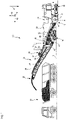
- a large road milling machine is shown as an example of the machine 10 according to the invention, the working device 12 of which is arranged with a milling drum 14 known per se, as is typical for large road milling machines, between the front chassis 16 and the rear chassis 18 .
- the running gears 16 and 18, which can be driven in each case preferably by a hydraulic motor (not shown) for the propulsion movement, can be steered and carry a machine frame 20, which in turn carries the working device 12.
- the machine 10 is thus a self-propelled vehicle.
- the direction of gravity is in the Figures 1 to 3 marked with an arrow g.
- the one to the character level of figure 1 orthogonal, parallel to the pitch axis Ni of the machine 10 running axis of rotation R rotatable milling drum 14 is shielded from the outside of the machine 10 by a milling drum box 22, which supports the milling drum 14 rotatably about the axis of rotation R.
- the milling drum box 22 is open to the subsoil U, on which the machine 10 with the running gears 16 and 18 stands and which the milling drum 14 removes, in order to enable the machine 10 to work the soil as intended.
- the machine frame 20 is connected to the chassis 16 and 18 via front lifting columns 17 and rear lifting columns 19 so that it can be adjusted in height along the yaw axis Gi, as a result of which the milling depth t of the milling drum 14 can be adjusted, for example.
- the machine 10 can be controlled from a control station 24 .
- the operator's stand 24 can be covered in a manner known per se.
- Soil material removed by the milling drum 14 during the intended soil tillage is conveyed by a transport device 26 from the working device 12 to a delivery location 28, where in the example shown it is transported to a transport truck accompanying the machine 10 during soil tillage at a distance in the direction of the roll axis Ro 30 is handed over.
- the transport device 26 comprises a receiving belt 32 located closer to the working device 12 and a discharge belt 34 which cooperates with the receiving belt 32 and is located further away from the working device 12.
- the receiving belt 32 can rotate, but is mounted on the machine frame 20 in an unchangeable manner with regard to its relative orientation to the machine frame 20 .
- the receiving belt 32 transfers the material it has conveyed to the discharge belt 34, which conveys the material that has been taken over to the delivery point 28.
- the discharge belt 34 is also rotatable, but can be pivoted relative to the machine frame 20 about a pivot axis S parallel to the yaw axis and can be tilted about a tilt axis orthogonal to the pivot axis S, so that the delivery location 28, which coincides with the discharge longitudinal end of the discharge belt 34, is approximately on the surface of a spherical cap is movable in order to adapt the delivery location 28 to the respective support vehicle.
- the transport device 26 is encased along its entire length by a housing 38 in order to prevent the external environment of the transport device 26 from being polluted by dust and material possibly falling from the transport device 26 .
- the part of the housing 38 located above the receiving belt 32 is largely realized by the machine frame 20 .
- the latter comprises a suction device 40 with a filter device 42.
- FIG 1 the suction device 40 is shown with a conveying fan 44' at the upper end of a filter housing 54.
- the filter device 42 is located on the suction side of the conveying fan 44', so that the air cleaned by the filter device 42 reaches the conveying fan 44' of the suction device 40 from figure 1 interspersed.
- the suction device 40 sucks in dust-laden air at a suction location 46, which can be located, for example, above the receiving belt 32, and conveys the dust-laden air in the specified sequence through a pre-filter 48 and through the filter device 42 to a blow-off location 50, which is either an outlet on the Conveyor fan 44', which blows off directly into the outside environment of the machine 10, or which can be an opening in the housing 38 above the discharge belt 34, through which the cleaned air is returned to the transport device 26, so that the cleaned air is combined escapes into the environment of the machine 10 with the removed soil material at the delivery point 28 .
- a suction location 46 which can be located, for example, above the receiving belt 32, and conveys the dust-laden air in the specified sequence through a pre-filter 48 and through the filter device 42 to a blow-off location 50, which is either an outlet on the Conveyor fan 44', which blows off directly into the outside environment of the machine 10, or which can be an opening in the housing 38 above the discharge belt 34,
- a filter body 52 is shown in the filter device 42 , the longitudinal axis of which is oriented essentially parallel to the transport direction or to the direction of travel of the discharge belt 34 .
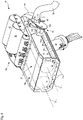
- the filter device 42 is more detailed than in FIG figure 1 shown.
- the filter device 42 includes the filter housing 54, in which in the example shown two, but very generally a plurality of filter bodies 52 are or is arranged.
- FIG 2 and 3 is the conveying fan 44 different from figure 1 shown in a lower portion of the filter housing 54 .
- the filter housing 54 or the filter device 42 is as in figure 1 functionally on the suction side of the conveying fan 44.
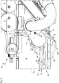
- figure 3 shows in particular the mirror-symmetrical design of the suction device 40 with regard to the first and the second hose lines 56 and 58, the pre-filter 48 and the conveying fan 44, which are each provided twice with respect to a mirror-symmetry plane spanned by the yaw axis Gi and the roll axis Ro, with the mirror symmetry applies to a stretched reference state, in which the discharge belt 34 and the transport direction of the discharge belt 34 are located in the plane of mirror symmetry.
- the conveying fan 44 conveys dust-laden air from the suction location 46 to the pre-filter 48 designed as a cyclone filter, where the dust-laden air is pre-cleaned in a manner known per se.
- the pre-cleaned air which is generally only polluted by fine dust with a grain size below a threshold size determined by the cyclone filter, is fed via a second hose line 58 to a bypass valve 60 , from where the pre-cleaned air enters the filter housing 54 .
- the filter housing 54 has a larger compartment 54a in which the filter bodies 52 are accommodated and has a smaller compartment 54b in which no filter bodies 52 are accommodated.
- the filter bodies 52 are therefore located in an interior space 57 of the filter housing 54 or of the compartment 54a.
- the bypass valve 60 comprises a valve component 60a that is movable relative to the filter housing 54 and a valve component 60b that is fixed to the filter housing.
- the movable valve component 60a can, for example, be pivotable by 180° about a valve axis V relative to the valve component 60b fixed to the filter housing.
- an outlet orifice 62 of the second hose line 58 is preferred as a conveying channel upstream with respect to the bypass valve 60 via one of the plate-shaped, planar movable valve component 60a protruding connection formation 61, while the valve component 60b fixed to the filter housing has two inlet openings 64 and 66, of which the inlet opening 64 leads via a connection formation 63a into the compartment 54a of the filter housing 54, in which filter bodies 52 are accommodated, whereas the inlet opening 66 leads via a connection formation 63b into the compartment 54b without a filter body.
- a handle 68 is used to adjust the bypass valve 60 between its filter operating position, in which the bypass valve 60 connects the outlet orifice 62 with the inlet orifice 64, and the bypass operating position, in which the bypass valve 60 connects the outlet orifice 62 with of the inlet mouth 66 connects.
- a motor drive can also be provided for adjusting the bypass valve 60 between its two operating positions.
- An elastic sealing formation 65a or 65b surrounding the respective inlet orifice 64 or 66 can protrude from the valve component 60b fixed to the filter housing from the boundary surface 60b1 pointing towards the movable valve component 60a in order to bridge a separating gap between the valve components 60a and 60b in a gas-tight manner.
- the conveying fan 44 always sucks air away via the preferably smaller compartment 54b of the filter housing 54 that is free of filter bodies 52 . Depending on the position of the bypass valve 60, the conveying fan 44 sucks in air via the filter body 52 in the compartment 54a or directly via the inlet opening 66 without further filtering.
- the preferably plate-shaped movable valve component 60a is constructed asymmetrically in such a way that it closes that inlet opening on the side of the filter housing-fixed valve component 60b which is not connected to the outlet opening 62 of the movable valve component 60a. So an unwanted suction of false air is avoided by the conveyor fan 44, so that the entire Conveying effect of the conveying fan 44 relates to the air flow actually intended for conveying.
- two filter bodies 52 are shown by way of example in dashed lines in the interior space 57 of the compartment 54a. Both filter bodies 52 each extend along a longitudinal axis L, which is also the axis of rotation D of the respective filter body 52 . The filter bodies 52 are arranged with longitudinal axes L parallel. The filter bodies 52 are each connected about the axis of rotation D by an in figure 5 Rotary drive 70 shown rotatable.
- the filter bodies 52 are cantilevered at only one longitudinal end on rotary bearings 72, from which they cantilever along their longitudinal axis L or axis of rotation D.
- the rotary bearings 72 which represent embodiments of the filter body receptacles mentioned above, are arranged on the filter housing 54 and have a coupling formation with which a counter-coupling formation on a filter body 52 can be detachably coupled.
- filter bodies 52 can be quickly exchanged on the one hand and, on the other hand, arranged in the filter housing 54 so as to be rotatable about the axis of rotation D without their own means of relative movement.
- the rotary drive 70 preferably interacts directly with rotary bearings 72, so that the filter body 52 itself does not have to have any design for direct power transmission with the rotary drive 70.
- the rotary drive 70 and the rotary bearings 72 can have gear wheels or tooth structures that mesh with one another, the gear wheel of the rotary drive 70 being driven by a motor.
- This motor can be a hydraulic motor or, preferably, an electric motor.
- Another peripheral section of the filter body 52 can always be arranged in such a way that it points in the direction of gravity g, so that gravity consequently supports the loosening and falling of filter cakes, which accumulate on the dirty side of the filter material of the filter body 52 during filter operation .
- a peripheral portion of the filter body 52 then points in the direction of gravity g when a surface of the filter material or normal vector emanating from the envelope of the filter material has at least one component running in the direction of the effect of gravity.
- FIG 6 A simplified cross-sectional view through the filter body 52 in a sectional plane orthogonal to the axis of rotation D is shown.
- the filter material 74 is a pleated filter material 74 which runs in a zigzag pattern around the axis of rotation D between an exemplary cylindrical radially outer envelope 74a and an exemplary cylindrical radially inner envelope 74b.
- Gravity acting direction g shown has the peripheral portion 75 of the filter material 74 in the gravitational acting direction g.
- the side of the filter material 74 pointing away from the axis of rotation D is the dirty side DS, on which filter cake forms during filter operation.
- the opposite side of the filter material 74 pointing to the axis of rotation D is the clean side CS, on which cleaned air flows after passing through the filter material 74 .
- the filter material 74 can be any porous material, such as a filter mat or a filter paper.
- the filter device 42 has a cleaning device 76 for removing filter cake from the filter material 74 of the filter bodies 52 .
- the cleaning device 76 comprises a pneumatic cleaning sub-device 76a and a mechanical cleaning sub-device 76b.
- the pneumatic partial cleaning device 76a comprises two compressed air tanks 78 and a valve arrangement 80 which is pneumatically connected to the compressed air tanks 78 and which is designed to discharge compressed air from the compressed air tanks 78 in bursts to the clean side CS of the filter material 74 of the filter bodies 52, so that the air pressure pressure surges that increase on the clean side CS compared to the dirty side DS are exerted on the filter material 74 . Due to these pressure surges, filter cake lying on the dirty side DS can be loosened or even ejected from the dirty side DS. The pressure surges can also bring about a deformation of the filter material 74 that supports the release of filter cake on the dirty side DS.
- a Control device 81 may be included, which controls the operation of the pneumatic cleaning sub-device 76a and the rotary drive 70.
- the pressure surges caused by the pneumatic cleaning sub-device 76a are matched to the rotational movement of the filter bodies 52 in terms of their duration and/or the distance between two consecutive pressure surges, so that it is ensured that the same circumferential section of the filter material 74 does not always point in the direction of gravity g when a pressure surge is applied. In this way it can be ensured that during a cleaning procedure the complete circumference of the filter body 52 is covered by the cleaning effect.
- a mechanical partial cleaning device 76b is provided, which supports the cleaning of the filter material 74 by subjecting it to mechanical stress.
- the mechanical partial cleaning device 76b comprises a wiper strip 82 which extends along the longitudinal axis or axis of rotation L or D of the filter body 52 .
- the wiper strip preferably extends through the radially outer envelope end 74a, which is cylindrical in the example shown, towards the axis of rotation D of the filter body 52, as is shown in figure 6 is shown.
- the radially outer folds 74c of the pleated filter material then scrape off the wiper strip 82, which temporarily increases the distance between two radially outer folds 74c that follow one another in the circumferential direction, so that filter cake caught between these folds can fall out more easily, and on the other hand, after the end of the contact engagement of the wiper strip 82 with a radially outer fold 74c, a force acting on the radially outer fold 74c and deforming it in the circumferential direction ends abruptly, so that the radially outer fold 74c, which was initially deformed in the circumferential direction, due to its material elasticity returns to its original shape, which can have a further filter cake-dissolving effect. Finally the Squeegee bar 82 mechanically along at least part of the filter material 74 and thus scrapes filter cake from the filter material 74 mechanically.
- the wiper strip 82 has a plurality of projections 84 on its side pointing towards the axis of rotation D, each of which protrudes from a support area 82a of the wiper strip 82 towards the axis of rotation D and thus towards the filter body 52.
- Each projection 84 has a web area 84a located closer to the carrier area 82a and preferably integrally connected thereto, and a stripping area 84b adjoining the web area 84a toward the axis of rotation D and preferably integrally connected thereto.
- the web area 84a of a projection 84 is shorter in the longitudinal direction of the wiper strip 82 than the wiper area 84b, which preferably projects beyond the web area 84a in the longitudinal direction of the wiper strip 82 on both sides.
- the wiping area 84b of each projection 84 thus provides the greatest possible wiping length and the web area 84a defines the deformation resistance of the projection 84 and thus the maximum load exerted by the wiping strip 82 on the filter material 74 .
- the wiper strip 82 can thus advantageously be made of stainless sheet steel. All projections 84 are preferably of identical design.
- the filter housing 54 has a housing base 86 pointing towards the discharge belt 34 when the filter device 42 is in the ready-to-use state, which in figure 5 is shown in dashed lines in a position lifted from the rest of the filter housing 55, ie the filter housing 54 without the housing base 86. In the usual, non-raised position, the housing base 86 is covered by the side wall of the filter housing 54 .
- the case back 86 is made of an elastomeric material, such as caoutchouc, gum, silicone rubber, etc.
- the case back 86 may be reinforced with inserts, such as fabric or scrim, to increase the case back 86's tear strength.
- the rest of the filter housing 55 is off in the example shown sheet metal built. However, this does not have to be the case.
- the filter housing 54 can have more than one wall made of an elastomeric material.
- the lower end 86a of the housing base 86 is coupled to an actuator 88 fixed to the filter housing 54 or to the housing 38 .
- the actuator 88 can be a pneumatic or a hydraulic actuator and can include a piston rod that can be extended from and retracted into a cylinder as the actuating element 90, or can be an electric or electromagnetic actuator whose actuating element 90 can be displaced electrically or electromagnetically.
- actuator 90 of actuator 88 is shown in phantom.
- the lower longitudinal end 86a of the housing base 86 is lifted off the rest of the filter housing 55, so that an outlet opening 92 is formed between the housing base 86, more precisely between its lower longitudinal end 86a and the rest of the filter housing 55, through which material to the transport device 26, more precisely towards the discharge belt 34, can be let out of the interior 57 of the filter housing 54, which has accumulated in the filter housing 54, in particular in the compartment 54a accommodating the filter bodies 52, in the course of operation.
- this is material which the extracted air has carried along and which has been filtered out of the air by the filter body 52 and/or which has been deposited on the inner walls of the filter housing 54 .
- the material can range from excavated soil material in the form of dust to shards of baked material.
- the removed soil material usually has a high level of moisture, since water is usually injected into the milling drum box 22 in order to prevent excessive formation of dust and to cool the milling cutters.
- the mineral soil material that has been removed tends to cake in a damp environment, a property that is particularly important for binding dust by injecting uses water. Mineral, rock-hard deposits can form on the inner surfaces of the filter housing.
- the deformable design of the housing base 86 through the use of elastomer material has another advantageous effect: through the targeted deformability of the housing base 86, soil material sticking to it can be detached from the housing base 86.
- An elastomeric wall of the filter housing 54 can be deformed in a simple manner by the cleaning device 76, more precisely by the pneumatic cleaning sub-device 76a. If this increases the pressure in the interior 57 of the filter housing 54, the deformable walls of the filter housing 54 bulge outwards, as a result of which the mineral layers of excavated soil material that are stuck and bonded to them flake off and can lie around loosely as shards in the interior 57 of the filter housing 54. The shards that have broken off can then be delivered to the transport device 26 through the outlet opening 92 and transported by it to the drop-off point 28 .
- the valve arrangement 80 can increase the pressure in the interior 57 of the filter housing 54, in particular in the compartment 54a, in a simple manner via pneumatic lines connected to it.
- the valve arrangement 80 can be actuated from the driver's station 24 .
- the control device 81 can also trigger a cleaning process of the filter housing 54 at predetermined time intervals by appropriately actuating the valve arrangement 80 .
- the conveying fan 44 can create a negative pressure in the filter housing 54 generate because the filter housing 54 is on the suction side of the conveyor fan 44.
- the filter housing 54 and thus its walls can be exposed to an alternating overpressure-underpressure load, which causes a flexing movement of the walls of the filter housing 54 further facilitates the detachment of hardened soil material sticking to it.
- the compressed air tanks 78 can also be connected via the valve arrangement 80 to an on-board compressor, which ensures a constant or quasi-constant level of compressed air in the compressed air tanks 78 .
Landscapes
- Engineering & Computer Science (AREA)
- Chemical & Material Sciences (AREA)
- Chemical Kinetics & Catalysis (AREA)
- Architecture (AREA)
- Civil Engineering (AREA)
- Structural Engineering (AREA)
- Mining & Mineral Resources (AREA)
- Mechanical Engineering (AREA)
- Physics & Mathematics (AREA)
- Geometry (AREA)
- Filtering Of Dispersed Particles In Gases (AREA)
Claims (12)
- Machine de traitement du sol autotractée (10), telle qu'une fraiseuse routière, un recycleur ou un surface miner, comprenant- un châssis de machine (20) supporté de manière réglable en hauteur par une pluralité de trains de roulement à chaînes ou/et à roues (16, 18),- un dispositif de travail (12) pour le traitement par enlèvement de matière d'une zone d'un sol (U), et- un dispositif d'aspiration (40), qui est conçu pour aspirer l'air chargé de poussière en au moins un lieu d'aspiration (46) hors d'au moins une zone de la machine et pour évacuer l'air aspiré en un lieu de soufflage (50) différent du lieu d'aspiration (46),le dispositif d'aspiration (40) présentant un dispositif de filtre (42) disposé le long d'un trajet d'écoulement de fonctionnement depuis ledit au moins un lieu d'aspiration (46) jusqu'au lieu de soufflage (50), le dispositif de filtre (42) comprenant :- un boîtier de filtre (54),- un corps de filtre (52) logé dans le boîtier de filtre (54), le corps de filtre (52) étant conçu pour éliminer les particules de poussière de l'air traversant le dispositif de filtre (42),caractérisée en ce que le dispositif de filtre (42) présente une soupape de dérivation (60) réglable entre au moins deux positions de fonctionnement différentes, une position de fonctionnement de filtre reliant ledit au moins un lieu d'aspiration (46) au lieu de soufflage (50) en traversant le corps de filtre (52), et une position de fonctionnement de dérivation reliant ledit au moins un lieu d'aspiration (46) au lieu de soufflage (50) en contournant le corps de filtre (52).
- Machine de traitement du sol autotractée (10) selon la revendication 1, caractérisée en ce que la soupape de dérivation (60) relie, dans la position de fonctionnement du filtre, ledit au moins un lieu d'aspiration (46) au boîtier de filtre (54) de telle sorte qu'un espace intérieur (57) du boîtier de filtre (54), recevant le corps de filtre (52), fait partie de la conduite d'écoulement (56, 58) reliant ledit au moins un lieu d'aspiration (46) au lieu de soufflage (56, 58) pour l'air chargé de poussière, et en ce que la soupape de dérivation (60), dans la position de fonctionnement en dérivation, relie ledit au moins un lieu d'aspiration (46) au lieu de soufflage (50) en contournant l'espace intérieur (57) du boîtier de filtre (54) recevant le corps de filtre (52).
- Machine de traitement du sol autotractée (10) selon la revendication 1 ou 2, caractérisée en ce que la soupape de dérivation (60) comprend un composant de soupape (60a) mobile par rapport au boîtier de filtre (54) et un composant de soupape fixe par rapport au boîtier de filtre (60b), le composant de soupape mobile (60a) pouvant être déplacé en translation par rapport au composant de soupape fixe par rapport au boîtier de filtre (60b) autour d'un axe de soupape (V) par rapport au composant de soupape fixe par rapport au boîtier de filtre (60b) ou/et pouvant pivoter selon un angle prédéterminé.
- Machine de traitement du sol autotractée (10) selon la revendication 3, caractérisée en ce qu'une embouchure de sortie (62) d'un canal de transport (58) situé en amont par rapport à la soupape de dérivation (60) est reliée au composant de soupape mobile (60a).
- Machine de traitement du sol autotractée (10) selon la revendication 3 ou 4, caractérisée en ce que le composant de soupape fixe par rapport au boîtier de filtre (60b) présente deux embouchures d'entrée (64, 66), dont une première embouchure d'entrée (64) mène dans un premier compartiment (54a) du boîtier de filtre (54), dans lequel est logé au moins un corps de filtre (52).
- Machine de traitement du sol autotractée (10) selon la revendication 5, caractérisée en ce qu'une deuxième embouchure d'entrée (66) mène dans un deuxième compartiment (54b) du boîtier de filtre (54) qui ne fournit pas d'effet de filtre.
- Machine de traitement du sol autotractée (10) selon l'une des revendications 5 ou 6, caractérisée en ce que le composant de soupape mobile (60a) est construit de manière à obturer l'embouchure d'entrée (64, 66) qui n'est pas relié à l'embouchure de sortie (62) du composant de soupape mobile (60a).
- Machine de traitement du sol autotractée (10) selon l'une des revendications 3 à 7, caractérisée en ce que le composant de soupape mobile (60a) ou/et le composant de soupape fixe par rapport au boîtier de filtre (60b) est/sont réalisé(s) avec une surface limite plane (60b1) au moins sur les côtés des composants de soupape (60a, 60b) qui se font face.
- Machine de traitement du sol autotractée (10) selon l'une des revendications 4 à 8, y compris la revendication 4 ou 5,
caractérisée en ce que les embouchures d'entrée (64, 66) ou l'embouchure de sortie (62) sont pourvues de formations d'étanchéité (65a, 65b) faisant saillie par rapport à l'autre composant de soupape (60a, 60b) respectif, afin de combler une fente de séparation entre le composant de soupape mobile (60a) et le composant de soupape fixe par rapport au boîtier de filtre (60b). - Machine de traitement du sol autotractée (10) selon l'une des revendications 4 à 9, en tenant compte de la revendication 4,
caractérisée en ce que le composant de soupape mobile (60a) comprend un élément plan en forme de plaque à partir duquel s'étend au moins une formation de raccordement (61) pour le raccordement du canal de transport conducteur d'air (58) sur le côté amont du composant de soupape mobile (60a). - Machine de traitement du sol autotractée (10) selon l'une des revendications 3 à 10,
caractérisée en ce que le composant de soupape fixe par rapport au boîtier de filtre (60b) comprend un élément plan en forme de plaque à partir duquel s'étend au moins une formation de raccordement (63a, 63b) sur le côté aval du composant de soupape fixe par rapport au boîtier de filtre (60b). - Machine de traitement du sol autotractée (10) selon l'une des revendications précédentes,
caractérisée en ce que la soupape de dérivation (60) présente un entraînement de soupape par lequel la soupape de dérivation (60) peut être déplacée entre au moins deux de ses positions de fonctionnement lors de l'actionnement d'un interrupteur de commande sur le poste de conduite (24) de la machine de traitement du sol.
Applications Claiming Priority (1)
| Application Number | Priority Date | Filing Date | Title |
|---|---|---|---|
| DE102019132889.6A DE102019132889A1 (de) | 2019-12-03 | 2019-12-03 | Bodenbearbeitungsmaschine mit Staubabsaugung mit wahlweiser Filterung der abgesaugten staubbelasteten Luft |
Publications (2)
| Publication Number | Publication Date |
|---|---|
| EP3832021A1 EP3832021A1 (fr) | 2021-06-09 |
| EP3832021B1 true EP3832021B1 (fr) | 2022-11-02 |
Family
ID=73694731
Family Applications (1)
| Application Number | Title | Priority Date | Filing Date |
|---|---|---|---|
| EP20211018.5A Active EP3832021B1 (fr) | 2019-12-03 | 2020-12-01 | Machine de traitement de sols avec extraction de poussière avec filtrage optionnel de l'air sale aspiré |
Country Status (4)
| Country | Link |
|---|---|
| US (1) | US11851829B2 (fr) |
| EP (1) | EP3832021B1 (fr) |
| CN (1) | CN112900208B (fr) |
| DE (1) | DE102019132889A1 (fr) |
Families Citing this family (1)
| Publication number | Priority date | Publication date | Assignee | Title |
|---|---|---|---|---|
| EP4065903A4 (fr) * | 2019-11-30 | 2023-12-27 | Work Air Technologies Pty Ltd | Système de climatisation et de filtration |
Family Cites Families (9)
| Publication number | Priority date | Publication date | Assignee | Title |
|---|---|---|---|---|
| SE451947B (sv) * | 1984-05-30 | 1987-11-09 | Nederman Philip & Co Ab | Filterrensanordning |
| DE10223819B4 (de) | 2002-05-28 | 2005-05-12 | Wirtgen Gmbh | Fräsmaschine zum Bearbeiten von Bodenoberflächen, sowie Verfahren zum Entsorgen von während der Fräsbearbeitung entstehenden Stäuben und Dämpfen an einer Fräsmaschine |
| DE102004007716B3 (de) * | 2004-02-16 | 2005-06-16 | Wirtgen Gmbh | Fräsmaschine sowie Verfahren zum Bearbeiten von Bodenoberflächen |
| CN101970759B (zh) * | 2008-03-12 | 2014-05-07 | 马林公司 | 用于磨削路面的改进的刨路机 |
| CN202638181U (zh) * | 2012-06-20 | 2013-01-02 | 浙江吉天环保科技有限公司 | 内滤式粉尘过滤设备 |
| DE102012211635B4 (de) | 2012-07-04 | 2024-07-04 | Robert Bosch Gmbh | Partikelabsaugvorrichtung |
| DE102017008745A1 (de) | 2016-09-20 | 2018-03-22 | Mann + Hummel Gmbh | Feinstaub-Abscheidevorrichtung für ein Fahrzeug |
| DE102017127086A1 (de) * | 2017-11-17 | 2019-05-23 | Vorwerk & Co. Interholding Gmbh | Regenerierbarer Luftfilter |
| US11260977B2 (en) * | 2018-12-04 | 2022-03-01 | The Boeing Company | Filtration apparatus for use with aircraft |
-
2019
- 2019-12-03 DE DE102019132889.6A patent/DE102019132889A1/de not_active Withdrawn
-
2020
- 2020-11-05 CN CN202011224598.4A patent/CN112900208B/zh active Active
- 2020-11-19 US US16/952,282 patent/US11851829B2/en active Active
- 2020-12-01 EP EP20211018.5A patent/EP3832021B1/fr active Active
Also Published As
| Publication number | Publication date |
|---|---|
| DE102019132889A1 (de) | 2021-06-10 |
| CN112900208B (zh) | 2023-09-15 |
| CN112900208A (zh) | 2021-06-04 |
| US11851829B2 (en) | 2023-12-26 |
| US20210164173A1 (en) | 2021-06-03 |
| EP3832021A1 (fr) | 2021-06-09 |
Similar Documents
| Publication | Publication Date | Title |
|---|---|---|
| EP1564332B1 (fr) | Fraiseuse et procédé pour travailler le sol | |
| EP2256250B1 (fr) | Dispositif mobile destiné à enlever des produits de remplissage d'une surface | |
| EP3225738B1 (fr) | Fraiseuse de sol, en particulier engin de fraisage de chaussée destiné à enlever de la matière du sol et son procédé de fonctionnement | |
| DE2758827C2 (de) | Auf einem Fahrzeug kippbar befestigter, mehrstufiger Abscheider | |
| DE102013106996B4 (de) | Waggonreinigungsanlage | |
| DE3135898A1 (de) | "verfahren und vorrichtung zum beschichten von gegenstaenden" | |
| DE2916131A1 (de) | Vorrichtung zur behandlung einer oberflaeche | |
| DE3710283C2 (de) | Einrichtung zum Abbau und Abtransport von kontaminiertem Erdreich | |
| DE69928176T2 (de) | Fräsmaschine mit einer Vorrichtung zum Absaugen und Verarbeiten von Staub | |
| EP3315666B1 (fr) | Dispositif et procédé de réception des balayures | |
| EP3832021B1 (fr) | Machine de traitement de sols avec extraction de poussière avec filtrage optionnel de l'air sale aspiré | |
| DE102010011418A1 (de) | Vorrichtung, System und Verfahren zur Reinigung von Kunstrasen | |
| DE102013104412A1 (de) | Reinigungsvorrichtung für eine Gleisanlage sowie ein mit einer solchen Reinigungsvorrichtung ausgestattetes Schienenfahrzeug | |
| EP3832020B1 (fr) | Machine de traitement de sols avec extraction de poussière filtrée avec boîtier de filtre à déformation élastique | |
| DE102021118686A1 (de) | Bodenfräsmaschine und verfahren zum absaugen und ausblasen staubbelasteter luft bei einer bodenfräsmaschine | |
| EP3832022B1 (fr) | Machine de traitement de sols avec extraction de poussière et cartouches filtrantes rotatives | |
| EP2815062B1 (fr) | Dispositif de forage à sec avec aspiration des déblais de forage | |
| EP3597828B1 (fr) | Fraiseuse routière | |
| CH364803A (de) | Selbstaufnehmende Kehrmaschine für Startbahnen, Strassen, Wege oder dergleichen mit Unterdruckförderung | |
| DE102009060719A1 (de) | Verfahren zum Aufnehmen von Streugut einer Straßenfräsmaschine und Vorrichtung zum Durchführen des Verfahrens | |
| DE202004002444U1 (de) | Fräsmaschine zum Bearbeiten von Bodenoberflächen | |
| EP4204184A1 (fr) | Machine à détonation et procédé pour faire fonctionner une machine à détonation | |
| EP4406398B1 (fr) | Moissonneuse automotrice | |
| DE4140978C2 (de) | Vorrichtung zum Sandstrahlen von Wandflächen | |
| EP2135540B1 (fr) | Machine de nettoyage du sol |
Legal Events
| Date | Code | Title | Description |
|---|---|---|---|
| PUAI | Public reference made under article 153(3) epc to a published international application that has entered the european phase |
Free format text: ORIGINAL CODE: 0009012 |
|
| STAA | Information on the status of an ep patent application or granted ep patent |
Free format text: STATUS: THE APPLICATION HAS BEEN PUBLISHED |
|
| AK | Designated contracting states |
Kind code of ref document: A1 Designated state(s): AL AT BE BG CH CY CZ DE DK EE ES FI FR GB GR HR HU IE IS IT LI LT LU LV MC MK MT NL NO PL PT RO RS SE SI SK SM TR |
|
| STAA | Information on the status of an ep patent application or granted ep patent |
Free format text: STATUS: REQUEST FOR EXAMINATION WAS MADE |
|
| 17P | Request for examination filed |
Effective date: 20210913 |
|
| RBV | Designated contracting states (corrected) |
Designated state(s): AL AT BE BG CH CY CZ DE DK EE ES FI FR GB GR HR HU IE IS IT LI LT LU LV MC MK MT NL NO PL PT RO RS SE SI SK SM TR |
|
| GRAP | Despatch of communication of intention to grant a patent |
Free format text: ORIGINAL CODE: EPIDOSNIGR1 |
|
| STAA | Information on the status of an ep patent application or granted ep patent |
Free format text: STATUS: GRANT OF PATENT IS INTENDED |
|
| RIC1 | Information provided on ipc code assigned before grant |
Ipc: B65G 69/18 20060101ALI20220114BHEP Ipc: B28D 7/02 20060101ALI20220114BHEP Ipc: E01C 23/12 20060101ALI20220114BHEP Ipc: E01C 23/088 20060101AFI20220114BHEP |
|
| INTG | Intention to grant announced |
Effective date: 20220202 |
|
| GRAJ | Information related to disapproval of communication of intention to grant by the applicant or resumption of examination proceedings by the epo deleted |
Free format text: ORIGINAL CODE: EPIDOSDIGR1 |
|
| STAA | Information on the status of an ep patent application or granted ep patent |
Free format text: STATUS: REQUEST FOR EXAMINATION WAS MADE |
|
| GRAP | Despatch of communication of intention to grant a patent |
Free format text: ORIGINAL CODE: EPIDOSNIGR1 |
|
| STAA | Information on the status of an ep patent application or granted ep patent |
Free format text: STATUS: GRANT OF PATENT IS INTENDED |
|
| INTC | Intention to grant announced (deleted) | ||
| INTG | Intention to grant announced |
Effective date: 20220516 |
|
| GRAS | Grant fee paid |
Free format text: ORIGINAL CODE: EPIDOSNIGR3 |
|
| GRAA | (expected) grant |
Free format text: ORIGINAL CODE: 0009210 |
|
| STAA | Information on the status of an ep patent application or granted ep patent |
Free format text: STATUS: THE PATENT HAS BEEN GRANTED |
|
| AK | Designated contracting states |
Kind code of ref document: B1 Designated state(s): AL AT BE BG CH CY CZ DE DK EE ES FI FR GB GR HR HU IE IS IT LI LT LU LV MC MK MT NL NO PL PT RO RS SE SI SK SM TR |
|
| REG | Reference to a national code |
Ref country code: GB Ref legal event code: FG4D Free format text: NOT ENGLISH |
|
| REG | Reference to a national code |
Ref country code: CH Ref legal event code: EP Ref country code: AT Ref legal event code: REF Ref document number: 1528832 Country of ref document: AT Kind code of ref document: T Effective date: 20221115 |
|
| REG | Reference to a national code |
Ref country code: DE Ref legal event code: R096 Ref document number: 502020001929 Country of ref document: DE |
|
| REG | Reference to a national code |
Ref country code: IE Ref legal event code: FG4D Free format text: LANGUAGE OF EP DOCUMENT: GERMAN |
|
| REG | Reference to a national code |
Ref country code: NL Ref legal event code: FP |
|
| REG | Reference to a national code |
Ref country code: SE Ref legal event code: TRGR |
|
| REG | Reference to a national code |
Ref country code: LT Ref legal event code: MG9D |
|
| PG25 | Lapsed in a contracting state [announced via postgrant information from national office to epo] |
Ref country code: PT Free format text: LAPSE BECAUSE OF FAILURE TO SUBMIT A TRANSLATION OF THE DESCRIPTION OR TO PAY THE FEE WITHIN THE PRESCRIBED TIME-LIMIT Effective date: 20230302 Ref country code: NO Free format text: LAPSE BECAUSE OF FAILURE TO SUBMIT A TRANSLATION OF THE DESCRIPTION OR TO PAY THE FEE WITHIN THE PRESCRIBED TIME-LIMIT Effective date: 20230202 Ref country code: LT Free format text: LAPSE BECAUSE OF FAILURE TO SUBMIT A TRANSLATION OF THE DESCRIPTION OR TO PAY THE FEE WITHIN THE PRESCRIBED TIME-LIMIT Effective date: 20221102 Ref country code: FI Free format text: LAPSE BECAUSE OF FAILURE TO SUBMIT A TRANSLATION OF THE DESCRIPTION OR TO PAY THE FEE WITHIN THE PRESCRIBED TIME-LIMIT Effective date: 20221102 Ref country code: ES Free format text: LAPSE BECAUSE OF FAILURE TO SUBMIT A TRANSLATION OF THE DESCRIPTION OR TO PAY THE FEE WITHIN THE PRESCRIBED TIME-LIMIT Effective date: 20221102 |
|
| PG25 | Lapsed in a contracting state [announced via postgrant information from national office to epo] |
Ref country code: RS Free format text: LAPSE BECAUSE OF FAILURE TO SUBMIT A TRANSLATION OF THE DESCRIPTION OR TO PAY THE FEE WITHIN THE PRESCRIBED TIME-LIMIT Effective date: 20221102 Ref country code: PL Free format text: LAPSE BECAUSE OF FAILURE TO SUBMIT A TRANSLATION OF THE DESCRIPTION OR TO PAY THE FEE WITHIN THE PRESCRIBED TIME-LIMIT Effective date: 20221102 Ref country code: LV Free format text: LAPSE BECAUSE OF FAILURE TO SUBMIT A TRANSLATION OF THE DESCRIPTION OR TO PAY THE FEE WITHIN THE PRESCRIBED TIME-LIMIT Effective date: 20221102 Ref country code: IS Free format text: LAPSE BECAUSE OF FAILURE TO SUBMIT A TRANSLATION OF THE DESCRIPTION OR TO PAY THE FEE WITHIN THE PRESCRIBED TIME-LIMIT Effective date: 20230302 Ref country code: HR Free format text: LAPSE BECAUSE OF FAILURE TO SUBMIT A TRANSLATION OF THE DESCRIPTION OR TO PAY THE FEE WITHIN THE PRESCRIBED TIME-LIMIT Effective date: 20221102 Ref country code: GR Free format text: LAPSE BECAUSE OF FAILURE TO SUBMIT A TRANSLATION OF THE DESCRIPTION OR TO PAY THE FEE WITHIN THE PRESCRIBED TIME-LIMIT Effective date: 20230203 |
|
| P01 | Opt-out of the competence of the unified patent court (upc) registered |
Effective date: 20230525 |
|
| PG25 | Lapsed in a contracting state [announced via postgrant information from national office to epo] |
Ref country code: SM Free format text: LAPSE BECAUSE OF FAILURE TO SUBMIT A TRANSLATION OF THE DESCRIPTION OR TO PAY THE FEE WITHIN THE PRESCRIBED TIME-LIMIT Effective date: 20221102 Ref country code: RO Free format text: LAPSE BECAUSE OF FAILURE TO SUBMIT A TRANSLATION OF THE DESCRIPTION OR TO PAY THE FEE WITHIN THE PRESCRIBED TIME-LIMIT Effective date: 20221102 Ref country code: EE Free format text: LAPSE BECAUSE OF FAILURE TO SUBMIT A TRANSLATION OF THE DESCRIPTION OR TO PAY THE FEE WITHIN THE PRESCRIBED TIME-LIMIT Effective date: 20221102 Ref country code: DK Free format text: LAPSE BECAUSE OF FAILURE TO SUBMIT A TRANSLATION OF THE DESCRIPTION OR TO PAY THE FEE WITHIN THE PRESCRIBED TIME-LIMIT Effective date: 20221102 Ref country code: CZ Free format text: LAPSE BECAUSE OF FAILURE TO SUBMIT A TRANSLATION OF THE DESCRIPTION OR TO PAY THE FEE WITHIN THE PRESCRIBED TIME-LIMIT Effective date: 20221102 |
|
| REG | Reference to a national code |
Ref country code: DE Ref legal event code: R097 Ref document number: 502020001929 Country of ref document: DE |
|
| REG | Reference to a national code |
Ref country code: BE Ref legal event code: MM Effective date: 20221231 |
|
| PG25 | Lapsed in a contracting state [announced via postgrant information from national office to epo] |
Ref country code: SK Free format text: LAPSE BECAUSE OF FAILURE TO SUBMIT A TRANSLATION OF THE DESCRIPTION OR TO PAY THE FEE WITHIN THE PRESCRIBED TIME-LIMIT Effective date: 20221102 Ref country code: LU Free format text: LAPSE BECAUSE OF NON-PAYMENT OF DUE FEES Effective date: 20221201 Ref country code: AL Free format text: LAPSE BECAUSE OF FAILURE TO SUBMIT A TRANSLATION OF THE DESCRIPTION OR TO PAY THE FEE WITHIN THE PRESCRIBED TIME-LIMIT Effective date: 20221102 |
|
| PLBE | No opposition filed within time limit |
Free format text: ORIGINAL CODE: 0009261 |
|
| STAA | Information on the status of an ep patent application or granted ep patent |
Free format text: STATUS: NO OPPOSITION FILED WITHIN TIME LIMIT |
|
| 26N | No opposition filed |
Effective date: 20230803 |
|
| PG25 | Lapsed in a contracting state [announced via postgrant information from national office to epo] |
Ref country code: IE Free format text: LAPSE BECAUSE OF NON-PAYMENT OF DUE FEES Effective date: 20221201 |
|
| PG25 | Lapsed in a contracting state [announced via postgrant information from national office to epo] |
Ref country code: SI Free format text: LAPSE BECAUSE OF FAILURE TO SUBMIT A TRANSLATION OF THE DESCRIPTION OR TO PAY THE FEE WITHIN THE PRESCRIBED TIME-LIMIT Effective date: 20221102 Ref country code: BE Free format text: LAPSE BECAUSE OF NON-PAYMENT OF DUE FEES Effective date: 20221231 |
|
| PG25 | Lapsed in a contracting state [announced via postgrant information from national office to epo] |
Ref country code: CY Free format text: LAPSE BECAUSE OF FAILURE TO SUBMIT A TRANSLATION OF THE DESCRIPTION OR TO PAY THE FEE WITHIN THE PRESCRIBED TIME-LIMIT Effective date: 20221102 |
|
| PG25 | Lapsed in a contracting state [announced via postgrant information from national office to epo] |
Ref country code: MK Free format text: LAPSE BECAUSE OF FAILURE TO SUBMIT A TRANSLATION OF THE DESCRIPTION OR TO PAY THE FEE WITHIN THE PRESCRIBED TIME-LIMIT Effective date: 20221102 |
|
| PG25 | Lapsed in a contracting state [announced via postgrant information from national office to epo] |
Ref country code: MC Free format text: LAPSE BECAUSE OF FAILURE TO SUBMIT A TRANSLATION OF THE DESCRIPTION OR TO PAY THE FEE WITHIN THE PRESCRIBED TIME-LIMIT Effective date: 20221102 |
|
| PG25 | Lapsed in a contracting state [announced via postgrant information from national office to epo] |
Ref country code: TR Free format text: LAPSE BECAUSE OF FAILURE TO SUBMIT A TRANSLATION OF THE DESCRIPTION OR TO PAY THE FEE WITHIN THE PRESCRIBED TIME-LIMIT Effective date: 20221102 Ref country code: MC Free format text: LAPSE BECAUSE OF FAILURE TO SUBMIT A TRANSLATION OF THE DESCRIPTION OR TO PAY THE FEE WITHIN THE PRESCRIBED TIME-LIMIT Effective date: 20221102 |
|
| PG25 | Lapsed in a contracting state [announced via postgrant information from national office to epo] |
Ref country code: BG Free format text: LAPSE BECAUSE OF FAILURE TO SUBMIT A TRANSLATION OF THE DESCRIPTION OR TO PAY THE FEE WITHIN THE PRESCRIBED TIME-LIMIT Effective date: 20221102 |
|
| REG | Reference to a national code |
Ref country code: CH Ref legal event code: PL |
|
| PG25 | Lapsed in a contracting state [announced via postgrant information from national office to epo] |
Ref country code: MT Free format text: LAPSE BECAUSE OF FAILURE TO SUBMIT A TRANSLATION OF THE DESCRIPTION OR TO PAY THE FEE WITHIN THE PRESCRIBED TIME-LIMIT Effective date: 20221102 |
|
| PG25 | Lapsed in a contracting state [announced via postgrant information from national office to epo] |
Ref country code: CH Free format text: LAPSE BECAUSE OF NON-PAYMENT OF DUE FEES Effective date: 20231231 |
|
| PG25 | Lapsed in a contracting state [announced via postgrant information from national office to epo] |
Ref country code: CH Free format text: LAPSE BECAUSE OF NON-PAYMENT OF DUE FEES Effective date: 20231231 |
|
| PG25 | Lapsed in a contracting state [announced via postgrant information from national office to epo] |
Ref country code: HU Free format text: LAPSE BECAUSE OF FAILURE TO SUBMIT A TRANSLATION OF THE DESCRIPTION OR TO PAY THE FEE WITHIN THE PRESCRIBED TIME-LIMIT; INVALID AB INITIO Effective date: 20201201 |
|
| PGFP | Annual fee paid to national office [announced via postgrant information from national office to epo] |
Ref country code: GB Payment date: 20251218 Year of fee payment: 6 |
|
| PGFP | Annual fee paid to national office [announced via postgrant information from national office to epo] |
Ref country code: AT Payment date: 20260113 Year of fee payment: 5 |
|
| PGFP | Annual fee paid to national office [announced via postgrant information from national office to epo] |
Ref country code: NL Payment date: 20251217 Year of fee payment: 6 Ref country code: FR Payment date: 20251218 Year of fee payment: 6 |
|
| PGFP | Annual fee paid to national office [announced via postgrant information from national office to epo] |
Ref country code: SE Payment date: 20251217 Year of fee payment: 6 |
|
| PGFP | Annual fee paid to national office [announced via postgrant information from national office to epo] |
Ref country code: DE Payment date: 20251222 Year of fee payment: 6 |
|
| PGFP | Annual fee paid to national office [announced via postgrant information from national office to epo] |
Ref country code: IT Payment date: 20251231 Year of fee payment: 6 |