EP3832058A1 - Dispositif de guidage pour un battant de porte coulissante - Google Patents
Dispositif de guidage pour un battant de porte coulissante Download PDFInfo
- Publication number
- EP3832058A1 EP3832058A1 EP19460065.6A EP19460065A EP3832058A1 EP 3832058 A1 EP3832058 A1 EP 3832058A1 EP 19460065 A EP19460065 A EP 19460065A EP 3832058 A1 EP3832058 A1 EP 3832058A1
- Authority
- EP
- European Patent Office
- Prior art keywords
- guiding device
- fixing part
- horizontal support
- horizontal
- chassis
- Prior art date
- Legal status (The legal status is an assumption and is not a legal conclusion. Google has not performed a legal analysis and makes no representation as to the accuracy of the status listed.)
- Pending
Links
Images


Classifications
-
- E—FIXED CONSTRUCTIONS
- E05—LOCKS; KEYS; WINDOW OR DOOR FITTINGS; SAFES
- E05D—HINGES OR SUSPENSION DEVICES FOR DOORS, WINDOWS OR WINGS
- E05D15/00—Suspension arrangements for wings
- E05D15/06—Suspension arrangements for wings for wings sliding horizontally more or less in their own plane
- E05D15/0621—Details, e.g. suspension or supporting guides
- E05D15/066—Details, e.g. suspension or supporting guides for wings supported at the bottom
- E05D15/0691—Top guides
-
- E—FIXED CONSTRUCTIONS
- E05—LOCKS; KEYS; WINDOW OR DOOR FITTINGS; SAFES
- E05D—HINGES OR SUSPENSION DEVICES FOR DOORS, WINDOWS OR WINGS
- E05D15/00—Suspension arrangements for wings
- E05D15/06—Suspension arrangements for wings for wings sliding horizontally more or less in their own plane
- E05D15/0621—Details, e.g. suspension or supporting guides
- E05D15/0626—Details, e.g. suspension or supporting guides for wings suspended at the top
- E05D15/0656—Bottom guides
-
- E—FIXED CONSTRUCTIONS
- E05—LOCKS; KEYS; WINDOW OR DOOR FITTINGS; SAFES
- E05Y—INDEXING SCHEME ASSOCIATED WITH SUBCLASSES E05D AND E05F, RELATING TO CONSTRUCTION ELEMENTS, ELECTRIC CONTROL, POWER SUPPLY, POWER SIGNAL OR TRANSMISSION, USER INTERFACES, MOUNTING OR COUPLING, DETAILS, ACCESSORIES, AUXILIARY OPERATIONS NOT OTHERWISE PROVIDED FOR, APPLICATION THEREOF
- E05Y2201/00—Constructional elements; Accessories therefor
- E05Y2201/60—Suspension or transmission members; Accessories therefor
- E05Y2201/622—Suspension or transmission members elements
- E05Y2201/64—Carriers
-
- E—FIXED CONSTRUCTIONS
- E05—LOCKS; KEYS; WINDOW OR DOOR FITTINGS; SAFES
- E05Y—INDEXING SCHEME ASSOCIATED WITH SUBCLASSES E05D AND E05F, RELATING TO CONSTRUCTION ELEMENTS, ELECTRIC CONTROL, POWER SUPPLY, POWER SIGNAL OR TRANSMISSION, USER INTERFACES, MOUNTING OR COUPLING, DETAILS, ACCESSORIES, AUXILIARY OPERATIONS NOT OTHERWISE PROVIDED FOR, APPLICATION THEREOF
- E05Y2800/00—Details, accessories and auxiliary operations not otherwise provided for
- E05Y2800/34—Form stability
- E05Y2800/342—Deformable
- E05Y2800/344—Deformable elastically
Definitions
- the present invention relates to a guiding device for a sliding door, to be placed on the top or bottom of the sliding door wing.
- the proposed device works with various sliding systems, and allows for smooth guiding and closing of the sliding door. It also serves to stabilize the sliding door wing movement along top or bottom guide rails.
- the proposed invention can be applied to regular sliding doors as well as to the wings in the pieces of furniture such as cabinets, wardrobes and the like.
- Korean patent KR101867038 (B1 ) describes a bathroom cabinet including a smoothly moving sliding door.
- a protrusion part is formed on front surfaces of upper, lower, and side plates.
- Upper and lower guide grooves closely adhered to upper and lower roller devices are formed in the protrusion part of the upper and lower plates.
- a door insertion groove closely adhered to a side surface of the sliding door is formed in the protrusion part of the side plate.
- Upper roller device comprises an upper roller including an upper fixed part fixed to the upper part of the sliding door, and a vertical rotating part hinge-coupled to one end of the horizontal fixed part, provided with a spring and having a roller disposed on a top. Resiliency is obtained by making a rotatable joint combined with a spring.
- Both ends of the spring are fixed to the middle part of the horizontal and vertical rotating parts of the upper roller, respectively.
- the roller presses the wing downwards by an upper roller which is a guide roller. No horizontal adjustment of the wing relative to the guide rails is possible.
- a lower roller is fixed to the lower part of the sliding door.
- the invention presented in Japanese patent document JP2017086417 (A ) relates to a partition storage unit having a sliding door.
- a guide roller provided at the tip of an arm member on a short length side is slidably engaged with a rail provided on a front side
- a guide roller provided at the tip of an arm member on a long length side is slidably engaged with a rail member provided on a back side.
- the bottom roller of the storage unit presses it together with the upper guiding rails upwards, while the upper rollers of the wing only guide the wing in these rails. They provide adjustment only in vertical direction along rotation axis of the guiding rollers.
- the wing upper rollers are hanged at the bottom sides of rigid brackets mounted to the sliding door which is supported on rollers mounted rigidly at the door wing bottom edge.
- Korean patent document KR20160135545 (A ) describes a sliding door frame structure for a built-in wardrobe.
- a rail recess frame which forms a horizontal facing unit touching the upper panel is installed in an upper panel of the wardrobe.
- a plurality of vertical guide units are formed directly under the horizontal facing unit to form a rail recess.
- Horizontal rollers installed in an upper part of a sliding door via an upper frame are inserted into the rail recesses.
- Vertical rollers carrying the door wing weight are installed at a lower part of the sliding door via a lower frame and are seated in the protruding rails.
- the bottom rollers of the wing are mounted to the bent brackets mounted rigidly at the door wing bottom edge. None is mentioned whether the brackets are elastic, so it is supposed they are rigid to ensure necessary stiffness of the device.
- the brackets are bent rather to hide the bottom rails below the wardrobe front plane.
- FIG. 1 Another Korean patent document KR20030045977 (A ) discloses a sliding roller structure for cabinet door that comprises a vertical upper roller mounted on an upper end of an inside of a cabinet door, a horizontal bottom roller mounted on a bottom end, an upper guide rail into which the upper roller is inserted to be driven along, wherein the upper guide rail is provided on the upper portion of a main body of a cabinet, and a bottom guide rail into which the bottom roller is inserted to be driven along.
- the bottom guide rail is provided on the bottom portion of the main body of the cabinet, so that the cabinet door is opened and closed in sliding manner.
- This invention is similar to that of KR20160135545 (A ): the upper and bottom rollers of the wings are mounted to the bent brackets mounted rigidly at the door wings' upper/bottom edges. Again, nothing is mentioned whether the brackets are elastic, so it is supposed they are rigid. The bent brackets hide the bottom rails behind the cabinet front plane.
- Still another Korean patent document KR101654926 (A ) discloses a roller rotating device for a sliding door that includes: the guide rails mounted on the upper and bottom surfaces of a furniture main body having a storage space, a sliding door, and a door fixing brackets installed on the upper and lower sides of the sliding door.
- the roller device further includes: a fixing member fixed to one side of the door fixing bracket, and a rotating member having a roller moving along the guide rail.
- the upper rollers carry entire weight of the sliding door wing. Elasticity of the mounting secured by the use of two screw springs is only for enabling slight turning of the bracket around vertical axis to prevent its deadlock in the guide turns.
- Japanese invention JP2004100400 provides a sliding door device for a storage fitting such as a sideboard, a book-shelf, or a showcase, which has a guide wheel arranged on the upper portion of the storage fitting and carries out opening/closing movement on a guide rail arranged on the upper portion of a sliding door.
- the sliding door is prevented from derailing during the opening/closing movement even if a slight manufacturing defect exists in the sliding door or in a fitting body.
- the sliding door device is formed of the sliding door, a lower bearing member constituting a sliding door frame, a lower guide body composed of a guide, a retaining roll, and a retaining portion, and a lower guide rail.
- the guide is detachably mounted on the lower bearing member, and provided with a lower guide wheel which is rotatable on an almost horizontal plane.
- the retaining roll is mounted on the lower bearing member together with the guide, for rotating on a vertical plane.
- the retaining portion sets the height of the retaining roll as appropriate.
- the lower guide rail has an almost gate-shaped cross section, into which the lower guide wheel and the retaining roll are loosely fitted.
- the height of the roll with respect to the lower guide rail is adjustable by the retaining portion of the lower guide body.
- Horizontal roller in lower bracket retains position of the sliding wing in horizontal direction, but the bracket is not prone to bending.
- a runner member comprises: a case part which is attached to a door board, an adjuster part which is ascendably/descendably housed in the case part, and a rail engaging part which is attached above the adjuster part and horizontally turned.
- the rail engaging part is urged in one direction of rotation via a spring, and a pair of guide rollers, the diameter of which is smaller in dimension than an interval between both lip parts of the upper rail, is attached in almost equidistant positions to sandwich a rotating shaft in between.
- the runner mechanism consists of two main parts, the upper one i.e. the rail engaging part having two horizontal rollers rotatable around vertical axis having a spring.
- British patent document GB2338018 proposes a wheeled top-guide for rolling movement of a door along a track having a first roller on a first axle in rolling engagement with one wall of a track, and a vertically oriented torsion member connected via a horizontal arm to a second axle and second roller.
- a torque is induced in the torsion rod, said torque maintaining said rollers in firm rolling contact with both side walls of said track.
- One of these two horizontal rollers is mounted on a rotatable arm with a spring which is external to the roller.
- a sliding door upper runner comprises an angle plate, with two horizontal rollers mounted on horizontal part of this plate.
- the rotation axis of one of the rollers is fixed on a tilting arm which is hinged on horizontal part of the plate.
- the tilting arm is tensioned by a spring mounted on rotation axis of the roller, and comprises a limiter of the arm tilt.
- the other roller is rotatable around its own axis fixed to horizontal part of the plate.
- Each horizontal roller is engaged with one of two opposite vertical walls of the U-shaped guide rail.
- a guiding device for a sliding door comprises a chassis and rollers rotatable around axles mounted on supports fastened to the chassis.
- the chassis is shaped from a single, metallic or plastic, or composite plate, and comprises a fixing part suitable to be fixed to the door wing, a vertical intermediate part, first horizontal support of first roller axle, an arm, and second horizontal support of second roller axle.
- the fixing part has at least two fixing holes for screws, bolts, pins, or rivets that immobilize the device on the door wing.
- First horizontal support is protruding from the fixing part, while second horizontal support is protruding from the arm having vertically oriented cross-section. This means that the part of the plate the arm is shaped from is vertical and perpendicular to second horizontal support.
- the arm is joined to the fixing part of the plate through vertical intermediate part protruding from the fixing part.
- the arm has a bow-shaped segment between vertical intermediate part and second horizontal support. This segment ensures resiliency of the arm.
- First roller is horizontal and is mounted on vertical axle assembled on first horizontal support.
- Second roller is also horizontal and is assembled on vertical axle that projects from second horizontal support.
- the fixing part is rectangular with rounded edges. It can be shaped in any convenient form, e.g. semicircle, triangle, trapezium, etc. Sharp edges are rounded to prevent injury of the user.
- the fixing holes shaped in the fixing part of the plate are suitable to install the chassis of the guiding device on the sliding door wing with the use of screws, bolts, pins, or rivets.
- the chassis is fixed to vertical side of the door wing, and therefore the plane of the fixing part is vertical.
- the chassis is installed on the top, relatively narrow horizontal surface of the sliding door wing. In this case the plane of the fixing part is horizontal.
- the plate of the chassis is made of a material, be it metal, plastic or composite, having Young's modulus ranging from 160 to 210 GPa, yield strength of 760-800 MPa, preferably 780 MPa for 0.2% elongation, and tensile strength of 1100-1300 MPa, preferably 1180 MPa.
- a layered structure is recommended, e.g. a metal sheet having both sides covered with plastic layers.
- low carbon steel comprising 17.0% of chromium, 6.7% of nickel, and 0.9% of manganese is advised.
- This low carbon steel may further comprise 0.6% of silica, 0.2% of copper, 0.1% of molybdenum, and 0.1% of carbon.
- the guide rail may be shaped with a plurality of vertical walls. Most common rail is U-shaped to receive one or more guiding devices of one sliding door wing. If two wings are expected to move along the same rail, a double-U-shaped (or W-shaped) guide rail is a common choice. The rail can have even more tracks and be triple-U-shaped and so on.
- the guiding device guides the door wing along the rail and secures its smooth motion provided that the horizontal rollers cooperate with opposite tracks of a U-shaped guide rail.
- a U-shaped rail or U-shaped segment of the multiple-U-shaped rail is used to guide one sliding door wing.
- two parallel door wings can be guided along one U-shaped rail.
- one guiding device fixed to one wing cooperates with both sides of one wall of the rail, and the other guiding device fixed to the other wing - with both sides of second wall of the U-shaped rail.
- the guide rail can be multiple-U-shaped and then the horizontal rollers of each device guiding one door wing cooperate with opposite sides of the same vertical wall of the U-shaped segment.
- three sliding door wings can be guided along a W-shaped rail.
- the fixing part is fixed to the door wing with use of C-shaped intermediate stiffening washer protecting against delamination of the door wing plate.
- the guiding device in one embodiment is adapted to cooperate with top guide rail, while in another embodiment it is adapted to cooperate with bottom guide rail.
- the difference is in that in the former case the rollers, their axles and supports, as well as the arm and intermediate part are positioned above both the fixing part and the top surface of the door wing, whereas in the latter case they are positioned below the fixing part and the bottom surface of the door wing.
- the guiding device for a sliding door comprises a chassis and rollers rotatable around axles mounted on supports fastened to the chassis.
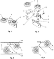
- the chassis is shaped from a single steel plate and comprises a rectangular fixing part 1, a vertical intermediate part 1a that protrudes from the fixing part 1, first horizontal support 2, an arm 3, and second horizontal support 4.
- the fixing part 1 has at least two fixing holes 8 suitable to fix the chassis of the guiding device to the sliding door wing 17 with screws 10, or bolts, or pins, or rivets. All edges of the plate are rounded.
- First horizontal support 2 is protruding from the fixing part 1
- second horizontal support 4 is protruding from an arm 3 having vertically oriented cross-section and which is joined to the fixing part 1 through vertical intermediate part 1a protruding from the fixing part 1.
- the arm 3 has a bow-shaped segment between vertical intermediate part 1a and second horizontal support 4 to ensure resiliency of the arm 3.
- First roller 6 is horizontal and is mounted on vertical axle 5 on first horizontal support 2
- second roller 7 is horizontal as well, and is mounted on vertical axle 5 on second horizontal support 4.
- the plane of the fixing part 1 is vertical, while in another version this plane is horizontal.
- the plate of the chassis is made of low carbon steel having Young's modulus of 180-200 GPa, yield strength of 780 MPa for 0.2% elongation, and tensile strength of 1180 MPa.
- the steel used comprises 17.0% of chromium, 6.7% of nickel, 0.9% of manganese, 0.6% of silica, 0.2% of copper, 0.1% of molybdenum, and 0.1% of carbon. All percentage values include a tolerance of +/- 1%.
- the horizontal rollers 6 and 7 cooperate with opposite tracks 18 of a U-shaped guide rail. In another embodiment the horizontal rollers 6 and 7 cooperate with opposite tracks 18 of a U-shaped segment of a multiple-U-shaped guide rail 11. Still in another embodiment the horizontal rollers 6 and 7 cooperate with opposite sides of the same track 18 of the guide rail.
- C-shaped intermediate stiffening washer 16 It can be used with horizontal fixing part 1 which is screwed to the board at its top surface. In this case the washer counteracts tearing forces leading to delamination of the door wing plate and keeps the board edges in place.
- C-shaped intermediate stiffening washer 16 When used with vertical fixing part 1 which is screwed to vertical surface of the board the C-shaped intermediate stiffening washer 16 must have one wall enlarged to fit the fixing part 1 and to be screwed together. Also, both side walls of C-shaped intermediate stiffening washer 16 can be enlarged which is advised in case of the door wings made of mineral or organic glass, ceramics, and the like fragile materials.
- the preferred embodiment of the guiding device cooperates with top guide rail, but it can be easily adapted to cooperate with bottom guide rail. In most arrangements it is sufficient to turn both the rail and the guiding device upside down, because the guiding device does not bear the door wing weight.
- a complete system may further comprise masking strips 12, 13, 14 and 15 that cover the rails and the door board edges. These strips can be shaped as grips of the door wings.
Landscapes
- Engineering & Computer Science (AREA)
- Mechanical Engineering (AREA)
- Support Devices For Sliding Doors (AREA)
Priority Applications (1)
| Application Number | Priority Date | Filing Date | Title |
|---|---|---|---|
| EP19460065.6A EP3832058A1 (fr) | 2019-12-04 | 2019-12-04 | Dispositif de guidage pour un battant de porte coulissante |
Applications Claiming Priority (1)
| Application Number | Priority Date | Filing Date | Title |
|---|---|---|---|
| EP19460065.6A EP3832058A1 (fr) | 2019-12-04 | 2019-12-04 | Dispositif de guidage pour un battant de porte coulissante |
Publications (1)
| Publication Number | Publication Date |
|---|---|
| EP3832058A1 true EP3832058A1 (fr) | 2021-06-09 |
Family
ID=69137702
Family Applications (1)
| Application Number | Title | Priority Date | Filing Date |
|---|---|---|---|
| EP19460065.6A Pending EP3832058A1 (fr) | 2019-12-04 | 2019-12-04 | Dispositif de guidage pour un battant de porte coulissante |
Country Status (1)
| Country | Link |
|---|---|
| EP (1) | EP3832058A1 (fr) |
Cited By (1)
| Publication number | Priority date | Publication date | Assignee | Title |
|---|---|---|---|---|
| DE102023111733A1 (de) | 2023-05-05 | 2024-11-07 | Hettich-Heinze Gmbh & Co. Kg | Führungsvorrichtung und Möbel |
Citations (12)
| Publication number | Priority date | Publication date | Assignee | Title |
|---|---|---|---|---|
| US2668317A (en) * | 1952-02-25 | 1954-02-09 | Arcadia Metal Products Inc | Guide device for a sliding door |
| GB789750A (en) * | 1955-06-09 | 1958-01-29 | Beckett Laycock & Watkinson | Improvements in or relating to sliding doors and the like |
| GB2338018A (en) | 1998-06-04 | 1999-12-08 | Stanley Works | A wheeled top guide for a sliding door having a spring loaded wheel |
| KR20030045977A (ko) | 2001-12-03 | 2003-06-12 | 주식회사 새턴바스 | 수납장 문의 슬라이딩 로울러 구조 |
| JP2004100400A (ja) | 2002-09-12 | 2004-04-02 | Shimodaira:Kk | 引戸装置 |
| JP2006194027A (ja) | 2005-01-17 | 2006-07-27 | Sekisui House Ltd | 引戸の上部ガイド構造 |
| EP2913467A1 (fr) | 2014-02-28 | 2015-09-02 | Laguna Invest Sp. z o.o. S.K.A. | Guide supérieur de porte coulissante |
| KR101654926B1 (ko) | 2015-12-31 | 2016-09-07 | 주식회사 다인스 | 슬라이딩 도어의 롤러 회전장치 |
| KR20160135545A (ko) | 2015-05-18 | 2016-11-28 | 구자호 | 붙박이장용 슬라이딩 도어 프레임 구조 |
| JP2017086417A (ja) | 2015-11-09 | 2017-05-25 | 大建工業株式会社 | 間仕切り収納ユニット |
| GB2547197A (en) * | 2016-02-09 | 2017-08-16 | Shush Doors Ltd | Carriage for sliding door |
| KR101867038B1 (ko) | 2017-04-18 | 2018-07-17 | 우주웰보드 주식회사 | 미닫이식 도어를 구비한 욕실수납장 |
-
2019
- 2019-12-04 EP EP19460065.6A patent/EP3832058A1/fr active Pending
Patent Citations (12)
| Publication number | Priority date | Publication date | Assignee | Title |
|---|---|---|---|---|
| US2668317A (en) * | 1952-02-25 | 1954-02-09 | Arcadia Metal Products Inc | Guide device for a sliding door |
| GB789750A (en) * | 1955-06-09 | 1958-01-29 | Beckett Laycock & Watkinson | Improvements in or relating to sliding doors and the like |
| GB2338018A (en) | 1998-06-04 | 1999-12-08 | Stanley Works | A wheeled top guide for a sliding door having a spring loaded wheel |
| KR20030045977A (ko) | 2001-12-03 | 2003-06-12 | 주식회사 새턴바스 | 수납장 문의 슬라이딩 로울러 구조 |
| JP2004100400A (ja) | 2002-09-12 | 2004-04-02 | Shimodaira:Kk | 引戸装置 |
| JP2006194027A (ja) | 2005-01-17 | 2006-07-27 | Sekisui House Ltd | 引戸の上部ガイド構造 |
| EP2913467A1 (fr) | 2014-02-28 | 2015-09-02 | Laguna Invest Sp. z o.o. S.K.A. | Guide supérieur de porte coulissante |
| KR20160135545A (ko) | 2015-05-18 | 2016-11-28 | 구자호 | 붙박이장용 슬라이딩 도어 프레임 구조 |
| JP2017086417A (ja) | 2015-11-09 | 2017-05-25 | 大建工業株式会社 | 間仕切り収納ユニット |
| KR101654926B1 (ko) | 2015-12-31 | 2016-09-07 | 주식회사 다인스 | 슬라이딩 도어의 롤러 회전장치 |
| GB2547197A (en) * | 2016-02-09 | 2017-08-16 | Shush Doors Ltd | Carriage for sliding door |
| KR101867038B1 (ko) | 2017-04-18 | 2018-07-17 | 우주웰보드 주식회사 | 미닫이식 도어를 구비한 욕실수납장 |
Cited By (2)
| Publication number | Priority date | Publication date | Assignee | Title |
|---|---|---|---|---|
| DE102023111733A1 (de) | 2023-05-05 | 2024-11-07 | Hettich-Heinze Gmbh & Co. Kg | Führungsvorrichtung und Möbel |
| WO2024231124A1 (fr) | 2023-05-05 | 2024-11-14 | Hettich-Heinze Gmbh & Co. Kg | Dispositif de guidage et meuble |
Similar Documents
| Publication | Publication Date | Title |
|---|---|---|
| US7647729B2 (en) | Sliding door system | |
| EP1500765B1 (fr) | Porte coulissante | |
| US10000962B2 (en) | Guiding device for a sliding door | |
| EP2868858B1 (fr) | Porte de sécurité | |
| EP2924212B1 (fr) | Dispositif d'ouverture et de fermeture de porte coulissante | |
| US3771847A (en) | Over the cabinet door assembly | |
| CN110582615B (zh) | 用于可移动地支承家具部件的导向滑架 | |
| JP5658813B1 (ja) | ダブルガラススキン用のインナーガラススキン構造 | |
| RU2009141902A (ru) | Шарнирная рама сиденья транспортного средства, сиденье транспортного средства, в частности, сиденье моторного транспортного средства и способ изготовления узла сиденья транспортного средства | |
| ES2795360T3 (es) | Armario | |
| US11441346B2 (en) | Hinged door leaves for wardrobes, walk-in closets and pieces of furniture in general, provided with magnetic damping and return devices | |
| CN102665488A (zh) | 用于抽屉的导轨系统 | |
| JP3400785B2 (ja) | ウィンドシールドを有する化学天びん | |
| EP2584130B1 (fr) | Système coulissant pour une porte de meuble | |
| JP2017534345A (ja) | 摺動扉機構を有する家具物品 | |
| US11661773B2 (en) | Double bottom slider system and mechanism | |
| MXPA06006052A (es) | Mecanismo para una hoja de vidrio corredera. | |
| JP5953728B2 (ja) | 折戸装置 | |
| US3075255A (en) | Rolling panel closure means | |
| KR101867038B1 (ko) | 미닫이식 도어를 구비한 욕실수납장 | |
| KR102542345B1 (ko) | 가구 힌지, 가구 패널 및 가구 본체 | |
| KR20080076475A (ko) | 스윙 도어 | |
| KR101475933B1 (ko) | 박판형 미닫이 도어 | |
| KR200188830Y1 (ko) | 미닫이식 도어용 롤러 조립체 | |
| US20220316251A1 (en) | A sliding system |
Legal Events
| Date | Code | Title | Description |
|---|---|---|---|
| PUAI | Public reference made under article 153(3) epc to a published international application that has entered the european phase |
Free format text: ORIGINAL CODE: 0009012 |
|
| STAA | Information on the status of an ep patent application or granted ep patent |
Free format text: STATUS: THE APPLICATION HAS BEEN PUBLISHED |
|
| AK | Designated contracting states |
Kind code of ref document: A1 Designated state(s): AL AT BE BG CH CY CZ DE DK EE ES FI FR GB GR HR HU IE IS IT LI LT LU LV MC MK MT NL NO PL PT RO RS SE SI SK SM TR |
|
| RAP3 | Party data changed (applicant data changed or rights of an application transferred) |
Owner name: LAGUNA FABRYKA OKUC SPOLKA Z O.O. S.J. |
|
| STAA | Information on the status of an ep patent application or granted ep patent |
Free format text: STATUS: REQUEST FOR EXAMINATION WAS MADE |
|
| 17P | Request for examination filed |
Effective date: 20210922 |
|
| RBV | Designated contracting states (corrected) |
Designated state(s): AL AT BE BG CH CY CZ DE DK EE ES FI FR GB GR HR HU IE IS IT LI LT LU LV MC MK MT NL NO PL PT RO RS SE SI SK SM TR |
|
| STAA | Information on the status of an ep patent application or granted ep patent |
Free format text: STATUS: EXAMINATION IS IN PROGRESS |
|
| 17Q | First examination report despatched |
Effective date: 20240313 |