EP3832063A1 - Support element for supporting a flat element in a leaf frame of a window or door leaf and this complete window or door leaf - Google Patents
Support element for supporting a flat element in a leaf frame of a window or door leaf and this complete window or door leaf Download PDFInfo
- Publication number
- EP3832063A1 EP3832063A1 EP20210893.2A EP20210893A EP3832063A1 EP 3832063 A1 EP3832063 A1 EP 3832063A1 EP 20210893 A EP20210893 A EP 20210893A EP 3832063 A1 EP3832063 A1 EP 3832063A1
- Authority
- EP
- European Patent Office
- Prior art keywords
- profile
- hollow chamber
- support
- support element
- window
- Prior art date
- Legal status (The legal status is an assumption and is not a legal conclusion. Google has not performed a legal analysis and makes no representation as to the accuracy of the status listed.)
- Granted
Links
Images

Classifications
-
- E—FIXED CONSTRUCTIONS
- E06—DOORS, WINDOWS, SHUTTERS, OR ROLLER BLINDS IN GENERAL; LADDERS
- E06B—FIXED OR MOVABLE CLOSURES FOR OPENINGS IN BUILDINGS, VEHICLES, FENCES OR LIKE ENCLOSURES IN GENERAL, e.g. DOORS, WINDOWS, BLINDS, GATES
- E06B3/00—Window sashes, door leaves, or like elements for closing wall or like openings; Layout of fixed or moving closures, e.g. windows in wall or like openings; Features of rigidly-mounted outer frames relating to the mounting of wing frames
- E06B3/54—Fixing of glass panes or like plates
- E06B3/5409—Means for locally spacing the pane from the surrounding frame
-
- E—FIXED CONSTRUCTIONS
- E06—DOORS, WINDOWS, SHUTTERS, OR ROLLER BLINDS IN GENERAL; LADDERS
- E06B—FIXED OR MOVABLE CLOSURES FOR OPENINGS IN BUILDINGS, VEHICLES, FENCES OR LIKE ENCLOSURES IN GENERAL, e.g. DOORS, WINDOWS, BLINDS, GATES
- E06B3/00—Window sashes, door leaves, or like elements for closing wall or like openings; Layout of fixed or moving closures, e.g. windows in wall or like openings; Features of rigidly-mounted outer frames relating to the mounting of wing frames
- E06B3/04—Wing frames not characterised by the manner of movement
- E06B3/06—Single frames
- E06B3/08—Constructions depending on the use of specified materials
- E06B3/20—Constructions depending on the use of specified materials of plastics
- E06B3/22—Hollow frames
- E06B3/221—Hollow frames with the frame member having local reinforcements in some parts of its cross-section or with a filled cavity
- E06B3/222—Hollow frames with the frame member having local reinforcements in some parts of its cross-section or with a filled cavity with internal prefabricated reinforcing section members inserted after manufacturing of the hollow frame
Definitions
- the present invention relates to a carrier element for supporting a surface element in a sash frame of a window or door sash, the sash frame being constructed from profile sections of a hollow chamber profile and a reinforcing element being received in at least one hollow chamber of the hollow chamber profile, the carrier element being a support element for providing a support surface for comprises the surface element.
- the present invention relates to a window or door sash which comprises a carrier element according to the invention.
- glass block bridges are used in the prior art, as they are, for example, from DE 87 03 052 U1 as well as the DE 39 23 288 A1 are known.
- Such glass block bridges are injection molded parts made of a thermoplastic material and are inserted into the glass rebate of a window or door sash profile in order to hold the surface element to be used, in particular the insulating glazing to be used, in the required position in the frame.
- the dimension to be bridged by the glass block bridge corresponds to the difference between the clear frame dimension and the dimension of the surface element to be used.
- the weight of the surface element is directed over the glass block bridges into the geodetically lower horizontal profile section of the casement.
- the effect of this weight on the geodetically lower horizontal profile section of the sash frame can lead to severe bending of this profile section, which can have a negative impact on trouble-free opening and closing of the window, especially at high temperatures.
- the surface elements are glued into the sash frame so that their weight is evenly transferred. Such gluing of the planar element in the casement is, however, labor-intensive and cost-intensive.
- the present invention begins, which is based on the object of providing a carrier element for supporting a surface element in a casement of a window or door sash, which at least partially overcomes the disadvantages of the prior art.
- the usability of a window or door sash comprising the carrier element according to the invention should be ensured even with a high weight of the surface element.
- the surface element without gluing in the window or door sash comprising the carrier element according to the invention can be held, without the sash frame bending due to the weight of the planar element.
- the object of the present invention is to provide a window or door sash which comprises a carrier element according to the invention.
- a carrier element for supporting a surface element in a sash frame of a window or a door sash with the features of claim 1 or by a window or door sash with the features of claim 7.
- Preferred embodiments of the present invention are described in the dependent claims.
- the carrier element comprises, in addition to the support element for providing a support surface for the surface element, at least one support element for supporting the carrier element on a profile wall of the hollow chamber profile and at least one engagement element.
- the engagement element can come into engagement with the reinforcement element of an adjacent profile section and thus transmit at least a large part of the weight of the surface element to this profile section.
- the present invention lies in the provision of a carrier element for supporting a surface element in a sash frame of a window or door sash, the sash frame being constructed from profile sections of a hollow chamber profile and a reinforcing element being received in at least one hollow chamber of the hollow chamber profile, the carrier element being a support element for Providing a support surface for the planar element, wherein the carrier element is characterized according to the invention in that it also has at least one support element for support of the carrier element on a profile wall of a profile section of the hollow chamber profile and at least one engagement element which can be brought into engagement with the reinforcing element, which is received in a hollow chamber of the profile section which adjoins the profile section on whose one profile wall the support element is supported.
- the present invention relates to a window or door sash which has a sash frame formed from sections of a hollow chamber profile; a reinforcing element received in a hollow chamber of the hollow chamber profile; a surface element received in the sash; and comprises at least one support element according to the invention, wherein the at least one support element rests at least in sections on a profile wall of the geodetically lower profile section of the hollow chamber profile and the at least one engagement element engages with the reinforcing element which is in a hollow chamber of a profile section of the hollow chamber profile adjoining the geodetically lower profile section is arranged.
- window or door sash preferably refers to a sash of a plastic window or a plastic door.
- metal windows or metal doors as well as composite windows and composite doors are also possible.
- the main material of the sash profile of the window or door sash according to the invention is polyvinyl chloride (PVC), in particular hard PVC (PVC-U) or glass fiber reinforced PVC, which also has additives such.
- PVC polyvinyl chloride
- PVC-U hard PVC
- glass fiber reinforced PVC which also has additives such.
- B. stabilizers, plasticizers, pigments and the like are added, preferred.
- PVC can be dyed or dyed well and hardly absorbs water.
- the at least one engagement element is designed as at least one engagement rail, in particular as a pair of engagement rails. Insertion elements of this type designed as rails can easily be brought into the relevant position in the reinforcement element. It can be of particular benefit if the engagement element (s) has / have at least one contact section for contact with a wall of the reinforcement element. With a simple construction of the at least one engagement element, this ensures sufficient transfer of the weight of the surface element into the reinforcement element of the adjacent profile section.
- the at least one support element is designed as at least one support rail.
- the design of the at least one support element as a support rail offers a simple and reliable structure of the invention Support element. It can be advantageous if the at least one support element is designed as a pair of support rails. Tilting of the carrier element according to the invention can thus be prevented.
- Preferred materials for the carrier element are polymeric materials, such as polypropylene, polyamides, polyphenylsulfone (PPSU), polyvinylidene fluoride (PVDF), polyethersulfone (PES), polysulfone (PSU), polyphenylene sulfide (PPS), acrylonitrile-butadiene-styrene copolymer (ABS), Polyoxymethylene (POM), polyester carbonate (PESC) and ASA (acrylonitrile-styrene-acrylic ester terpolymer), as well as copolymers and blends of these polymers, whereby these polymer materials can also be fiber-reinforced, in particular glass fiber-reinforced, and / or metallic materials such as steel , Stainless steel, aluminum, aluminum die-cast alloys, zinc die-cast alloys or aluminum-zinc die-cast alloys, and / or composite materials of the materials mentioned.
- PPSU polyphenylsulfone
- the carrier element according to the invention is designed in several parts, in particular in two parts.
- the carrier element according to the invention has a cover element that can be connected to the at least one engagement element.
- a carrier element according to the invention designed in this way can be more easily mounted in a wing.
- the surface element is designed as insulating glazing, preferably as multi-pane insulating glazing.
- Insulating glazing has a particularly high weight of the planar element, so that the use of a carrier element according to the invention is particularly favorable.
- the support element according to the invention takes on the function of block bridges, whereby their number can be reduced in the wing according to the invention.
- the hollow chamber profile according to the invention is preferably made from polyvinyl chloride (PVC), in particular from hard PVC (PVC-U) or glass fiber reinforced PVC, which can also contain post-chlorinated PVC (PVC-C).
- PVC polyvinyl chloride
- PVC-U hard PVC
- PVC-C post-chlorinated PVC
- the hollow chamber profiles are preferably used to manufacture a sash of a plastic window or a plastic door.
- a window or door frame can be obtained by welding together mitered sections of a plastic hollow chamber profile.
- the window or door frame obtained is intended for installation in an opening in a wall of a building or can be installed in the opening in the wall of a building.
- the reinforcement element is made from a metallic material, in particular aluminum, steel or iron, from a fiber-reinforced polymer material, in particular a glass fiber-reinforced polymer material, or in sections from a combination of the materials mentioned. Such materials have proven to be particularly suitable in practice.
- carrier elements according to the invention are preferably arranged in the two corners geodetically arranged below in an installation situation, i.e. in the corners of the sash in which the geodetically lower, horizontally extending profile section is involved.
- a carrier according to the invention is arranged in the geodetically lower corner on the side on which the wing according to the invention is fixed to a frame by means of fittings so as to be rotatable.
- the carrier element according to the invention, the window or door sash according to the invention and individual parts thereof can also be produced line by line or in layers using a line-building or layer-building manufacturing process (e.g. 3D printing), but production of the carrier element according to the invention as a cast part is preferred Hollow chamber profile by means of extrusion or coextrusion and the reinforcement element by means of continuous casting.
- a line-building or layer-building manufacturing process e.g. 3D printing
- a carrier element 1 according to an embodiment of the present invention is shown in a perspective view.
- the carrier element 1 according to the invention is designed as a one-piece cast component made from a zinc die-cast alloy.
- the support element 1 according to the invention comprises a support element 2, which offers a suitable support surface for a surface element, in particular for insulating glazing, a support element 3 with which the support element 1 can be supported on a profile wall of a profile section of a hollow chamber profile, as well as engagement elements 4, 4 ', which can be brought into engagement with a reinforcing element 13 '( Fig. 2 ).
- the support element 2 is designed as a preferably flat support plate.
- the support element has a bore 6 or a plurality of bores through each of which a fastening means, in particular a screw, can be guided for fastening the carrier element 1 according to the invention to a sash frame 7 of a window sash 8 according to the invention.
- a support element 3 designed as a pair of support rails is integrally formed on the underside of the support plate.
- the support rails continue as engagement rails, which the engagement elements 4, 4 'of the carrier element 1 according to the in Fig. 1 represent embodiment of the present invention shown.
- the engagement elements 4, 4 ′ each have a contact section 9, 9 ′ at their ends.
- a cover plate 10 which in turn has one or more bores 6', through each of which a fastening means, in particular a screw, for further fastening the support element 1 according to the invention to a sash frame 7 of a window sash 8 according to the invention are guided can.
- the support element 2 and the cover plate 10 have an angled portion 11 on one side.
- FIG. 1 An installation situation of the in Fig. 1 support element 1 according to the invention shown in a casement 7 of a window sash 8 according to the invention formed from profile sections 12, 12 'is shown in Fig. 2 shown in a schematic plan view.
- the casement 7 is produced by welding mitered profile sections 12, 12 'of a plastic hollow chamber profile, wherein in Fig. 2 a corner area of the casement 7 is shown with a geodetically lower, horizontally extending profile section 12 in an installation situation and a vertically extending profile section 12 'connected to it.
- Reinforcing elements 13, 13 ' which are preferably designed as steel reinforcement and do not extend completely into the corners of the sash 7, are inserted into a hollow chamber of the profile sections 12, 12', which is usually referred to as a reinforcement chamber.
- the profile sections 12, 12 'thus have areas in which there is no reinforcing element.
- a surface element (not shown), which is preferably designed as insulating glazing, can be placed on the support element 2, which is designed as a support plate.
- the support element 3 is supported on a profile wall 14 of the profile section 12.
- the engaging elements 4, 4 'of the carrier element 1 according to the invention which are designed as engaging rails, rest against the corresponding profile wall 14' of the profile section 12 '.
- the end section of the engaging rails extends into the reinforcing element 13 'of the profile section 12'.
- the contact sections 9, 9 ' are in contact with a wall of the reinforcing element 13'.
- the weight of the surface element is largely transferred to the vertical profile section 12 ', so that the weight acting on the geodetically lower profile section 12 is reduced, which reduces the risk of the geodetically lower profile section 12 bending.
- Trouble-free opening and closing of the window comprising the sash 8 according to the invention is thus ensured.
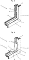
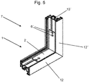
- FIGS. 3 to 5 The installation of the support element 1 according to the invention in a casement 7 is shown in FIGS. 3 to 5 in a sequence of perspective views of a corner area of a sash 7 of a window sash 8 ( Fig. 3 ), while ( Fig. 4 ) and after ( Fig. 5 ) the insertion of the carrier element 1 according to the invention shown.
- the corner area shown is in turn made up of the horizontally running profile section 12, which is geodetically lower in an installation situation, and the vertically running profile section 12 connected to it Profile section 12 'built up, with corresponding profile pieces of the plastic hollow chamber profile being mitred and welded together.
- Stiffening elements 13, 13 ' are pushed into the reinforcement chamber, the stiffening elements 13, 13' not extending all the way into the corners.
- the two grooves 15, 15 ' are dimensioned and spaced from one another in such a way that they are suitable for receiving the support elements 3, 3' formed as a pair of support rails and the engagement elements 4, 4 'formed as a pair of engagement rails.
- the contact sections 9, 9 'of the engagement elements 4, 4' are inserted into the grooves 15, 15 'on the side of the vertically running profile section 12' ( Fig. 4 ) and the support element 1 according to the invention is pushed into the corner area of the sash in a rotating manner until the contact sections 9, 9 'rest on the reinforcement element 13'. In this position, the support elements 3, 3 ′ also rest against the profile wall 14 of the lower profile section 12. This state is in Fig. 5 shown.
- the support element 1 according to the invention is fixed to the sash frame by means of fastening means (not shown) guided through the bores 16, 16 'of the vertically running profile section 12' and corresponding bores 6 'in the support element 2 of the support element 1, the fastening means being inserted into the reinforcing element 13'. of the vertically running profile section 12 'so that the weight of a surface element placed on the support element 2 of the support element 1 according to the invention does not only act on the lower profile section 12, but at least partially also on the reinforcement element 13' of the vertically running profile section 12 '.
- the wing 8 according to the invention rests against a frame via seals in the closed state of the window.
- the wing 8 according to the invention is rotatably mounted on the frame by means of fittings (not shown).
- the present invention has been described by way of example with reference to sashes of a window. It goes without saying that the present invention can also be correspondingly applied to door leaves.
Landscapes
- Engineering & Computer Science (AREA)
- Civil Engineering (AREA)
- Structural Engineering (AREA)
- Wing Frames And Configurations (AREA)
- Securing Of Glass Panes Or The Like (AREA)
Applications Claiming Priority (1)
| Application Number | Priority Date | Filing Date | Title |
|---|---|---|---|
| DE202019106774.8U DE202019106774U1 (de) | 2019-12-05 | 2019-12-05 | Trägerelement zum Abstützen eines Flächenelements in einem Flügelrahmen eines Fenster- oder Türflügels sowie dieses umfassender Fenster- oder Türflügel |
Publications (3)
| Publication Number | Publication Date |
|---|---|
| EP3832063A1 true EP3832063A1 (fr) | 2021-06-09 |
| EP3832063C0 EP3832063C0 (fr) | 2024-03-06 |
| EP3832063B1 EP3832063B1 (fr) | 2024-03-06 |
Family
ID=73654664
Family Applications (1)
| Application Number | Title | Priority Date | Filing Date |
|---|---|---|---|
| EP20210893.2A Active EP3832063B1 (fr) | 2019-12-05 | 2020-12-01 | Élément de support pour supporter un élément plat dans un cadre de battant de fenêtre ou de porte ainsi que battant de fenêtre ou de porte le comprenant |
Country Status (2)
| Country | Link |
|---|---|
| EP (1) | EP3832063B1 (fr) |
| DE (1) | DE202019106774U1 (fr) |
Citations (5)
| Publication number | Priority date | Publication date | Assignee | Title |
|---|---|---|---|---|
| DE8703052U1 (de) | 1987-02-27 | 1987-07-09 | Grundmeier KG, 4835 Rietberg | Glasklotz |
| DE3923288A1 (de) | 1989-07-14 | 1991-02-07 | Deflex Dichtsysteme Gmbh | Glasfalzeinlage |
| DE29807020U1 (de) * | 1998-03-27 | 1998-08-06 | Herbes, Wilhelm, 49774 Lähden | Fensterflügel- und Verklotzungselement zur Verwendung in einem Fensterflügel |
| US20060254150A1 (en) * | 2005-05-13 | 2006-11-16 | Van Kirk William R | Apparatus for supporting glass in a window assembly |
| AT509673A1 (de) * | 2010-03-24 | 2011-10-15 | Pfisterer Rudolf | Flügel für ein fenster oder eine tür |
Family Cites Families (4)
| Publication number | Priority date | Publication date | Assignee | Title |
|---|---|---|---|---|
| DE3213176A1 (de) * | 1982-04-08 | 1983-10-13 | Arnold 7918 Illertissen Butzbach | Isolierglasfenster |
| DE19925495A1 (de) * | 1999-06-04 | 2000-12-07 | Peter Willrich | Einsatzstück zur Befestigung einer Scheibe in einem Rahmen |
| DE102018106525B4 (de) * | 2018-03-20 | 2025-06-05 | PHI Technik für Fenster und Türen GmbH | Verbindungsanordnung |
| DE202018106077U1 (de) * | 2018-10-24 | 2018-11-07 | SCHÜCO International KG | Glasträgerkonstruktion und Rahmenkonstruktion |
-
2019
- 2019-12-05 DE DE202019106774.8U patent/DE202019106774U1/de active Active
-
2020
- 2020-12-01 EP EP20210893.2A patent/EP3832063B1/fr active Active
Patent Citations (5)
| Publication number | Priority date | Publication date | Assignee | Title |
|---|---|---|---|---|
| DE8703052U1 (de) | 1987-02-27 | 1987-07-09 | Grundmeier KG, 4835 Rietberg | Glasklotz |
| DE3923288A1 (de) | 1989-07-14 | 1991-02-07 | Deflex Dichtsysteme Gmbh | Glasfalzeinlage |
| DE29807020U1 (de) * | 1998-03-27 | 1998-08-06 | Herbes, Wilhelm, 49774 Lähden | Fensterflügel- und Verklotzungselement zur Verwendung in einem Fensterflügel |
| US20060254150A1 (en) * | 2005-05-13 | 2006-11-16 | Van Kirk William R | Apparatus for supporting glass in a window assembly |
| AT509673A1 (de) * | 2010-03-24 | 2011-10-15 | Pfisterer Rudolf | Flügel für ein fenster oder eine tür |
Also Published As
| Publication number | Publication date |
|---|---|
| EP3832063C0 (fr) | 2024-03-06 |
| DE202019106774U1 (de) | 2021-03-08 |
| EP3832063B1 (fr) | 2024-03-06 |
Similar Documents
| Publication | Publication Date | Title |
|---|---|---|
| DE202019107047U1 (de) | Fenster- oder Türflügel sowie diesen umfassendes Fenster oder diesen umfassende Tür | |
| DE1509553A1 (de) | Fensterkonstruktion | |
| DE19963233A1 (de) | Rahmen für Fenster oder Türe | |
| EP3670808B1 (fr) | Module de cadre pour une porte ou une fenêtre | |
| EP2363567A2 (fr) | Cadre d'une fenêtre en matière synthétique ou d'une porte en matière synthétique ainsi que joint central associé | |
| EP0833998B1 (fr) | Profile creux de cadre de fenetre et chassis de fenetre a deux battants utilisant ce profile | |
| DE202021106912U1 (de) | Fenster- oder Türflügel, Blendrahmen sowie diese(n) umfassende(s) Fenster oder Tür | |
| EP3832063B1 (fr) | Élément de support pour supporter un élément plat dans un cadre de battant de fenêtre ou de porte ainsi que battant de fenêtre ou de porte le comprenant | |
| EP3828372B1 (fr) | Battant de fenêtre ou de porte ainsi que fenêtre ou porte comportant un tel battant | |
| EP2487313A1 (fr) | Construction de cadre pour une fenêtre ou une porte | |
| EP4083366A1 (fr) | Battant pour une fenêtre ou une porte, élément de fixation du verre pour un tel battant, fenêtre le comprenant, ainsi que porte le comprenant | |
| EP2428633B1 (fr) | Profilé de dormant pour construction de portes, fenêtres ou façades | |
| DE102019131361A1 (de) | Verstärkungselement für Fenster- oder Türhohlkammerprofile sowie Verfahren zur Verstärkung eines Fenster- oder Türhohlkammerprofils | |
| DE202020107305U1 (de) | Fenster | |
| EP4202168B1 (fr) | Battant de fenêtre ou de porte et fenêtre ou porte comprenant ledit battant | |
| EP4015756B1 (fr) | Battant pour une fenêtre ou une porte, ainsi qu'élément de renfort pour un tel battant | |
| EP2942467B1 (fr) | Porte dotée d'une poignée | |
| EP3828373A1 (fr) | Battant de fenêtre ou de porte ainsi que fenêtre ou porte comportant un tel battant | |
| DE20313884U1 (de) | Wärmegedämmtes Bauprofil aus Polyurethan mit innenliegender Gewebe-Verstärkung | |
| EP4390038A1 (fr) | Battant pour une fenêtre ou une porte, fenêtre le comprenant et porte le comprenant | |
| DE202013103305U1 (de) | Flügelüberdeckende Tür | |
| DE2026947A1 (de) | Metallkonstruktion, insbesondere zum Herstellen von Einsatzen, Befestigungen u dgl in Gebäuden | |
| DE202024107518U1 (de) | Türflügel sowie diesen umfassende Tür | |
| DE202024107512U1 (de) | Türflügel sowie diesen umfassende Tür | |
| DE202024107522U1 (de) | Türflügel sowie diesen umfassende Tür |
Legal Events
| Date | Code | Title | Description |
|---|---|---|---|
| PUAI | Public reference made under article 153(3) epc to a published international application that has entered the european phase |
Free format text: ORIGINAL CODE: 0009012 |
|
| STAA | Information on the status of an ep patent application or granted ep patent |
Free format text: STATUS: THE APPLICATION HAS BEEN PUBLISHED |
|
| AK | Designated contracting states |
Kind code of ref document: A1 Designated state(s): AL AT BE BG CH CY CZ DE DK EE ES FI FR GB GR HR HU IE IS IT LI LT LU LV MC MK MT NL NO PL PT RO RS SE SI SK SM TR |
|
| STAA | Information on the status of an ep patent application or granted ep patent |
Free format text: STATUS: REQUEST FOR EXAMINATION WAS MADE |
|
| 17P | Request for examination filed |
Effective date: 20211207 |
|
| RBV | Designated contracting states (corrected) |
Designated state(s): AL AT BE BG CH CY CZ DE DK EE ES FI FR GB GR HR HU IE IS IT LI LT LU LV MC MK MT NL NO PL PT RO RS SE SI SK SM TR |
|
| RAP1 | Party data changed (applicant data changed or rights of an application transferred) |
Owner name: REHAU INDUSTRIES SE & CO. KG |
|
| RAP3 | Party data changed (applicant data changed or rights of an application transferred) |
Owner name: REHAU INDUSTRIES SE & CO. KG |
|
| GRAP | Despatch of communication of intention to grant a patent |
Free format text: ORIGINAL CODE: EPIDOSNIGR1 |
|
| STAA | Information on the status of an ep patent application or granted ep patent |
Free format text: STATUS: GRANT OF PATENT IS INTENDED |
|
| INTG | Intention to grant announced |
Effective date: 20230918 |
|
| GRAS | Grant fee paid |
Free format text: ORIGINAL CODE: EPIDOSNIGR3 |
|
| GRAA | (expected) grant |
Free format text: ORIGINAL CODE: 0009210 |
|
| STAA | Information on the status of an ep patent application or granted ep patent |
Free format text: STATUS: THE PATENT HAS BEEN GRANTED |
|
| AK | Designated contracting states |
Kind code of ref document: B1 Designated state(s): AL AT BE BG CH CY CZ DE DK EE ES FI FR GB GR HR HU IE IS IT LI LT LU LV MC MK MT NL NO PL PT RO RS SE SI SK SM TR |
|
| REG | Reference to a national code |
Ref country code: CH Ref legal event code: EP |
|
| REG | Reference to a national code |
Ref country code: DE Ref legal event code: R096 Ref document number: 502020007230 Country of ref document: DE |
|
| REG | Reference to a national code |
Ref country code: IE Ref legal event code: FG4D Free format text: LANGUAGE OF EP DOCUMENT: GERMAN |
|
| U01 | Request for unitary effect filed |
Effective date: 20240404 |
|
| U07 | Unitary effect registered |
Designated state(s): AT BE BG DE DK EE FI FR IT LT LU LV MT NL PT SE SI Effective date: 20240412 |
|
| PG25 | Lapsed in a contracting state [announced via postgrant information from national office to epo] |
Ref country code: GR Free format text: LAPSE BECAUSE OF FAILURE TO SUBMIT A TRANSLATION OF THE DESCRIPTION OR TO PAY THE FEE WITHIN THE PRESCRIBED TIME-LIMIT Effective date: 20240607 |
|
| PG25 | Lapsed in a contracting state [announced via postgrant information from national office to epo] |
Ref country code: RS Free format text: LAPSE BECAUSE OF FAILURE TO SUBMIT A TRANSLATION OF THE DESCRIPTION OR TO PAY THE FEE WITHIN THE PRESCRIBED TIME-LIMIT Effective date: 20240606 Ref country code: HR Free format text: LAPSE BECAUSE OF FAILURE TO SUBMIT A TRANSLATION OF THE DESCRIPTION OR TO PAY THE FEE WITHIN THE PRESCRIBED TIME-LIMIT Effective date: 20240306 |
|
| PG25 | Lapsed in a contracting state [announced via postgrant information from national office to epo] |
Ref country code: ES Free format text: LAPSE BECAUSE OF FAILURE TO SUBMIT A TRANSLATION OF THE DESCRIPTION OR TO PAY THE FEE WITHIN THE PRESCRIBED TIME-LIMIT Effective date: 20240306 |
|
| PG25 | Lapsed in a contracting state [announced via postgrant information from national office to epo] |
Ref country code: RS Free format text: LAPSE BECAUSE OF FAILURE TO SUBMIT A TRANSLATION OF THE DESCRIPTION OR TO PAY THE FEE WITHIN THE PRESCRIBED TIME-LIMIT Effective date: 20240606 Ref country code: NO Free format text: LAPSE BECAUSE OF FAILURE TO SUBMIT A TRANSLATION OF THE DESCRIPTION OR TO PAY THE FEE WITHIN THE PRESCRIBED TIME-LIMIT Effective date: 20240606 Ref country code: HR Free format text: LAPSE BECAUSE OF FAILURE TO SUBMIT A TRANSLATION OF THE DESCRIPTION OR TO PAY THE FEE WITHIN THE PRESCRIBED TIME-LIMIT Effective date: 20240306 Ref country code: GR Free format text: LAPSE BECAUSE OF FAILURE TO SUBMIT A TRANSLATION OF THE DESCRIPTION OR TO PAY THE FEE WITHIN THE PRESCRIBED TIME-LIMIT Effective date: 20240607 Ref country code: ES Free format text: LAPSE BECAUSE OF FAILURE TO SUBMIT A TRANSLATION OF THE DESCRIPTION OR TO PAY THE FEE WITHIN THE PRESCRIBED TIME-LIMIT Effective date: 20240306 |
|
| PG25 | Lapsed in a contracting state [announced via postgrant information from national office to epo] |
Ref country code: IS Free format text: LAPSE BECAUSE OF FAILURE TO SUBMIT A TRANSLATION OF THE DESCRIPTION OR TO PAY THE FEE WITHIN THE PRESCRIBED TIME-LIMIT Effective date: 20240706 |
|
| PG25 | Lapsed in a contracting state [announced via postgrant information from national office to epo] |
Ref country code: SM Free format text: LAPSE BECAUSE OF FAILURE TO SUBMIT A TRANSLATION OF THE DESCRIPTION OR TO PAY THE FEE WITHIN THE PRESCRIBED TIME-LIMIT Effective date: 20240306 |
|
| PG25 | Lapsed in a contracting state [announced via postgrant information from national office to epo] |
Ref country code: CZ Free format text: LAPSE BECAUSE OF FAILURE TO SUBMIT A TRANSLATION OF THE DESCRIPTION OR TO PAY THE FEE WITHIN THE PRESCRIBED TIME-LIMIT Effective date: 20240306 |
|
| PG25 | Lapsed in a contracting state [announced via postgrant information from national office to epo] |
Ref country code: PL Free format text: LAPSE BECAUSE OF FAILURE TO SUBMIT A TRANSLATION OF THE DESCRIPTION OR TO PAY THE FEE WITHIN THE PRESCRIBED TIME-LIMIT Effective date: 20240306 |
|
| PG25 | Lapsed in a contracting state [announced via postgrant information from national office to epo] |
Ref country code: SK Free format text: LAPSE BECAUSE OF FAILURE TO SUBMIT A TRANSLATION OF THE DESCRIPTION OR TO PAY THE FEE WITHIN THE PRESCRIBED TIME-LIMIT Effective date: 20240306 |
|
| PG25 | Lapsed in a contracting state [announced via postgrant information from national office to epo] |
Ref country code: SM Free format text: LAPSE BECAUSE OF FAILURE TO SUBMIT A TRANSLATION OF THE DESCRIPTION OR TO PAY THE FEE WITHIN THE PRESCRIBED TIME-LIMIT Effective date: 20240306 Ref country code: SK Free format text: LAPSE BECAUSE OF FAILURE TO SUBMIT A TRANSLATION OF THE DESCRIPTION OR TO PAY THE FEE WITHIN THE PRESCRIBED TIME-LIMIT Effective date: 20240306 Ref country code: RO Free format text: LAPSE BECAUSE OF FAILURE TO SUBMIT A TRANSLATION OF THE DESCRIPTION OR TO PAY THE FEE WITHIN THE PRESCRIBED TIME-LIMIT Effective date: 20240306 Ref country code: PL Free format text: LAPSE BECAUSE OF FAILURE TO SUBMIT A TRANSLATION OF THE DESCRIPTION OR TO PAY THE FEE WITHIN THE PRESCRIBED TIME-LIMIT Effective date: 20240306 Ref country code: IS Free format text: LAPSE BECAUSE OF FAILURE TO SUBMIT A TRANSLATION OF THE DESCRIPTION OR TO PAY THE FEE WITHIN THE PRESCRIBED TIME-LIMIT Effective date: 20240706 Ref country code: CZ Free format text: LAPSE BECAUSE OF FAILURE TO SUBMIT A TRANSLATION OF THE DESCRIPTION OR TO PAY THE FEE WITHIN THE PRESCRIBED TIME-LIMIT Effective date: 20240306 |
|
| REG | Reference to a national code |
Ref country code: DE Ref legal event code: R097 Ref document number: 502020007230 Country of ref document: DE |
|
| U20 | Renewal fee for the european patent with unitary effect paid |
Year of fee payment: 5 Effective date: 20241204 |
|
| PLBE | No opposition filed within time limit |
Free format text: ORIGINAL CODE: 0009261 |
|
| STAA | Information on the status of an ep patent application or granted ep patent |
Free format text: STATUS: NO OPPOSITION FILED WITHIN TIME LIMIT |
|
| 26N | No opposition filed |
Effective date: 20241209 |
|
| PG25 | Lapsed in a contracting state [announced via postgrant information from national office to epo] |
Ref country code: MC Free format text: LAPSE BECAUSE OF FAILURE TO SUBMIT A TRANSLATION OF THE DESCRIPTION OR TO PAY THE FEE WITHIN THE PRESCRIBED TIME-LIMIT Effective date: 20240306 |
|
| REG | Reference to a national code |
Ref country code: CH Ref legal event code: PL |
|
| GBPC | Gb: european patent ceased through non-payment of renewal fee |
Effective date: 20241201 |
|
| PG25 | Lapsed in a contracting state [announced via postgrant information from national office to epo] |
Ref country code: GB Free format text: LAPSE BECAUSE OF NON-PAYMENT OF DUE FEES Effective date: 20241201 |
|
| PG25 | Lapsed in a contracting state [announced via postgrant information from national office to epo] |
Ref country code: CH Free format text: LAPSE BECAUSE OF NON-PAYMENT OF DUE FEES Effective date: 20241231 |
|
| PG25 | Lapsed in a contracting state [announced via postgrant information from national office to epo] |
Ref country code: IE Free format text: LAPSE BECAUSE OF NON-PAYMENT OF DUE FEES Effective date: 20241201 |
|
| U20 | Renewal fee for the european patent with unitary effect paid |
Year of fee payment: 6 Effective date: 20251125 |
|
| PG25 | Lapsed in a contracting state [announced via postgrant information from national office to epo] |
Ref country code: CY Free format text: LAPSE BECAUSE OF FAILURE TO SUBMIT A TRANSLATION OF THE DESCRIPTION OR TO PAY THE FEE WITHIN THE PRESCRIBED TIME-LIMIT; INVALID AB INITIO Effective date: 20201201 |