EP3832087B1 - Integrierte hybrid-stromanlage - Google Patents
Integrierte hybrid-stromanlage Download PDFInfo
- Publication number
- EP3832087B1 EP3832087B1 EP20178497.2A EP20178497A EP3832087B1 EP 3832087 B1 EP3832087 B1 EP 3832087B1 EP 20178497 A EP20178497 A EP 20178497A EP 3832087 B1 EP3832087 B1 EP 3832087B1
- Authority
- EP
- European Patent Office
- Prior art keywords
- engine
- water jacket
- generator
- coolant
- piping
- Prior art date
- Legal status (The legal status is an assumption and is not a legal conclusion. Google has not performed a legal analysis and makes no representation as to the accuracy of the status listed.)
- Active
Links
Images


Classifications
-
- F—MECHANICAL ENGINEERING; LIGHTING; HEATING; WEAPONS; BLASTING
- F01—MACHINES OR ENGINES IN GENERAL; ENGINE PLANTS IN GENERAL; STEAM ENGINES
- F01P—COOLING OF MACHINES OR ENGINES IN GENERAL; COOLING OF INTERNAL-COMBUSTION ENGINES
- F01P3/00—Liquid cooling
- F01P3/02—Arrangements for cooling cylinders or cylinder heads
-
- B—PERFORMING OPERATIONS; TRANSPORTING
- B64—AIRCRAFT; AVIATION; COSMONAUTICS
- B64D—EQUIPMENT FOR FITTING IN OR TO AIRCRAFT; FLIGHT SUITS; PARACHUTES; ARRANGEMENT OR MOUNTING OF POWER PLANTS OR PROPULSION TRANSMISSIONS IN AIRCRAFT
- B64D27/00—Arrangement or mounting of power plants in aircraft; Aircraft characterised by the type or position of power plants
- B64D27/02—Aircraft characterised by the type or position of power plants
- B64D27/30—Aircraft characterised by electric power plants
- B64D27/33—Hybrid electric aircraft
-
- B—PERFORMING OPERATIONS; TRANSPORTING
- B64—AIRCRAFT; AVIATION; COSMONAUTICS
- B64D—EQUIPMENT FOR FITTING IN OR TO AIRCRAFT; FLIGHT SUITS; PARACHUTES; ARRANGEMENT OR MOUNTING OF POWER PLANTS OR PROPULSION TRANSMISSIONS IN AIRCRAFT
- B64D27/00—Arrangement or mounting of power plants in aircraft; Aircraft characterised by the type or position of power plants
- B64D27/02—Aircraft characterised by the type or position of power plants
- B64D27/026—Aircraft characterised by the type or position of power plants comprising different types of power plants, e.g. combination of a piston engine and a gas-turbine
-
- B—PERFORMING OPERATIONS; TRANSPORTING
- B64—AIRCRAFT; AVIATION; COSMONAUTICS
- B64D—EQUIPMENT FOR FITTING IN OR TO AIRCRAFT; FLIGHT SUITS; PARACHUTES; ARRANGEMENT OR MOUNTING OF POWER PLANTS OR PROPULSION TRANSMISSIONS IN AIRCRAFT
- B64D33/00—Arrangement in aircraft of power plant parts or auxiliaries not otherwise provided for
- B64D33/08—Arrangement in aircraft of power plant parts or auxiliaries not otherwise provided for of power plant cooling systems
-
- F—MECHANICAL ENGINEERING; LIGHTING; HEATING; WEAPONS; BLASTING
- F01—MACHINES OR ENGINES IN GENERAL; ENGINE PLANTS IN GENERAL; STEAM ENGINES
- F01P—COOLING OF MACHINES OR ENGINES IN GENERAL; COOLING OF INTERNAL-COMBUSTION ENGINES
- F01P3/00—Liquid cooling
- F01P3/12—Arrangements for cooling other engine or machine parts
- F01P3/14—Arrangements for cooling other engine or machine parts for cooling intake or exhaust valves
-
- F—MECHANICAL ENGINEERING; LIGHTING; HEATING; WEAPONS; BLASTING
- F01—MACHINES OR ENGINES IN GENERAL; ENGINE PLANTS IN GENERAL; STEAM ENGINES
- F01P—COOLING OF MACHINES OR ENGINES IN GENERAL; COOLING OF INTERNAL-COMBUSTION ENGINES
- F01P3/00—Liquid cooling
- F01P3/20—Cooling circuits not specific to a single part of engine or machine
-
- F—MECHANICAL ENGINEERING; LIGHTING; HEATING; WEAPONS; BLASTING
- F01—MACHINES OR ENGINES IN GENERAL; ENGINE PLANTS IN GENERAL; STEAM ENGINES
- F01P—COOLING OF MACHINES OR ENGINES IN GENERAL; COOLING OF INTERNAL-COMBUSTION ENGINES
- F01P7/00—Controlling of coolant flow
- F01P7/14—Controlling of coolant flow the coolant being liquid
- F01P7/16—Controlling of coolant flow the coolant being liquid by thermostatic control
- F01P7/165—Controlling of coolant flow the coolant being liquid by thermostatic control characterised by systems with two or more loops
-
- F—MECHANICAL ENGINEERING; LIGHTING; HEATING; WEAPONS; BLASTING
- F02—COMBUSTION ENGINES; HOT-GAS OR COMBUSTION-PRODUCT ENGINE PLANTS
- F02B—INTERNAL-COMBUSTION PISTON ENGINES; COMBUSTION ENGINES IN GENERAL
- F02B63/00—Adaptations of engines for driving pumps, hand-held tools or electric generators; Portable combinations of engines with engine-driven devices
- F02B63/04—Adaptations of engines for driving pumps, hand-held tools or electric generators; Portable combinations of engines with engine-driven devices for electric generators
-
- F—MECHANICAL ENGINEERING; LIGHTING; HEATING; WEAPONS; BLASTING
- F02—COMBUSTION ENGINES; HOT-GAS OR COMBUSTION-PRODUCT ENGINE PLANTS
- F02B—INTERNAL-COMBUSTION PISTON ENGINES; COMBUSTION ENGINES IN GENERAL
- F02B73/00—Combinations of two or more engines, not otherwise provided for
-
- F—MECHANICAL ENGINEERING; LIGHTING; HEATING; WEAPONS; BLASTING
- F02—COMBUSTION ENGINES; HOT-GAS OR COMBUSTION-PRODUCT ENGINE PLANTS
- F02F—CYLINDERS, PISTONS OR CASINGS, FOR COMBUSTION ENGINES; ARRANGEMENTS OF SEALINGS IN COMBUSTION ENGINES
- F02F1/00—Cylinders; Cylinder heads
- F02F1/02—Cylinders; Cylinder heads having cooling means
- F02F1/10—Cylinders; Cylinder heads having cooling means for liquid cooling
- F02F1/14—Cylinders with means for directing, guiding or distributing liquid stream
-
- F—MECHANICAL ENGINEERING; LIGHTING; HEATING; WEAPONS; BLASTING
- F02—COMBUSTION ENGINES; HOT-GAS OR COMBUSTION-PRODUCT ENGINE PLANTS
- F02F—CYLINDERS, PISTONS OR CASINGS, FOR COMBUSTION ENGINES; ARRANGEMENTS OF SEALINGS IN COMBUSTION ENGINES
- F02F1/00—Cylinders; Cylinder heads
- F02F1/24—Cylinder heads
- F02F1/26—Cylinder heads having cooling means
- F02F1/36—Cylinder heads having cooling means for liquid cooling
- F02F1/40—Cylinder heads having cooling means for liquid cooling cylinder heads with means for directing, guiding, or distributing liquid stream
-
- F—MECHANICAL ENGINEERING; LIGHTING; HEATING; WEAPONS; BLASTING
- F28—HEAT EXCHANGE IN GENERAL
- F28F—DETAILS OF HEAT-EXCHANGE AND HEAT-TRANSFER APPARATUS, OF GENERAL APPLICATION
- F28F1/00—Tubular elements; Assemblies of tubular elements
- F28F1/10—Tubular elements and assemblies thereof with means for increasing heat-transfer area, e.g. with fins, with projections, with recesses
- F28F1/12—Tubular elements and assemblies thereof with means for increasing heat-transfer area, e.g. with fins, with projections, with recesses the means being only outside the tubular element
- F28F1/24—Tubular elements and assemblies thereof with means for increasing heat-transfer area, e.g. with fins, with projections, with recesses the means being only outside the tubular element and extending transversely
-
- H—ELECTRICITY
- H02—GENERATION; CONVERSION OR DISTRIBUTION OF ELECTRIC POWER
- H02K—DYNAMO-ELECTRIC MACHINES
- H02K1/00—Details of the magnetic circuit
- H02K1/06—Details of the magnetic circuit characterised by the shape, form or construction
- H02K1/22—Rotating parts of the magnetic circuit
- H02K1/27—Rotor cores with permanent magnets
- H02K1/2786—Outer rotors
- H02K1/2787—Outer rotors the magnetisation axis of the magnets being perpendicular to the rotor axis
- H02K1/2789—Outer rotors the magnetisation axis of the magnets being perpendicular to the rotor axis the rotor consisting of two or more circumferentially positioned magnets
- H02K1/2791—Surface mounted magnets; Inset magnets
-
- H—ELECTRICITY
- H02—GENERATION; CONVERSION OR DISTRIBUTION OF ELECTRIC POWER
- H02K—DYNAMO-ELECTRIC MACHINES
- H02K9/00—Arrangements for cooling or ventilating
- H02K9/19—Arrangements for cooling or ventilating for machines with closed casing and closed-circuit cooling using a liquid cooling medium, e.g. oil
- H02K9/197—Arrangements for cooling or ventilating for machines with closed casing and closed-circuit cooling using a liquid cooling medium, e.g. oil in which the rotor or stator space is fluid-tight, e.g. to provide for different cooling media for rotor and stator
-
- F—MECHANICAL ENGINEERING; LIGHTING; HEATING; WEAPONS; BLASTING
- F01—MACHINES OR ENGINES IN GENERAL; ENGINE PLANTS IN GENERAL; STEAM ENGINES
- F01P—COOLING OF MACHINES OR ENGINES IN GENERAL; COOLING OF INTERNAL-COMBUSTION ENGINES
- F01P3/00—Liquid cooling
- F01P3/02—Arrangements for cooling cylinders or cylinder heads
- F01P2003/021—Cooling cylinders
-
- F—MECHANICAL ENGINEERING; LIGHTING; HEATING; WEAPONS; BLASTING
- F01—MACHINES OR ENGINES IN GENERAL; ENGINE PLANTS IN GENERAL; STEAM ENGINES
- F01P—COOLING OF MACHINES OR ENGINES IN GENERAL; COOLING OF INTERNAL-COMBUSTION ENGINES
- F01P2050/00—Applications
- F01P2050/20—Aircraft engines
-
- F—MECHANICAL ENGINEERING; LIGHTING; HEATING; WEAPONS; BLASTING
- F01—MACHINES OR ENGINES IN GENERAL; ENGINE PLANTS IN GENERAL; STEAM ENGINES
- F01P—COOLING OF MACHINES OR ENGINES IN GENERAL; COOLING OF INTERNAL-COMBUSTION ENGINES
- F01P2060/00—Cooling circuits using auxiliaries
- F01P2060/18—Heater
- F01P2060/185—Heater for alternators or generators
-
- Y—GENERAL TAGGING OF NEW TECHNOLOGICAL DEVELOPMENTS; GENERAL TAGGING OF CROSS-SECTIONAL TECHNOLOGIES SPANNING OVER SEVERAL SECTIONS OF THE IPC; TECHNICAL SUBJECTS COVERED BY FORMER USPC CROSS-REFERENCE ART COLLECTIONS [XRACs] AND DIGESTS
- Y02—TECHNOLOGIES OR APPLICATIONS FOR MITIGATION OR ADAPTATION AGAINST CLIMATE CHANGE
- Y02T—CLIMATE CHANGE MITIGATION TECHNOLOGIES RELATED TO TRANSPORTATION
- Y02T50/00—Aeronautics or air transport
- Y02T50/60—Efficient propulsion technologies, e.g. for aircraft
Definitions
- One or more example embodiments relate to an integrated hybrid power apparatus in which a water-cooling reciprocating engine and a water-cooling generator are integrated.
- a cooling device of a reciprocating engine may need to allow a mechanical body to reach a normal operating temperature within a short period of time and then maintain a consistent normal operating temperature within all speed ranges under all operating conditions.
- a cooling effect of the cooling device may depend on a type of a cooling medium (e.g., water, air, specific liquid), a flow velocity, a size of a radiating surface area of a radiator, a heat transfer property of a material, and a temperature difference between a cooling medium and an object to be cooled.
- a type of a cooling medium e.g., water, air, specific liquid
- a flow velocity e.g., water, air, specific liquid
- a size of a radiating surface area of a radiator e.g., a size of a radiating surface area of a radiator, a heat transfer property of a material
- a temperature difference between a cooling medium and an object to be cooled e.g., water, air, specific liquid
- Such an additional cooling device described above may not be an exclusive way to cool the reciprocating engine.
- For the cooling there are an air-cooling method and a water-cooling method.
- the water-cooling method may be more effective than the air-cooling method.
- a system for the water-cooling method may be more complicated and disadvantageous in terms of weight.
- Both the air-cooling method and the water-cooling method may be applied to an engine of a drone.
- a generator may generally use the air-cooling method, and thus may be disadvantageous in terms of efficiency.
- Korean Patent Application No. 10-2011-0074346 filed on July 27, 2011 discloses a cooling module and a method of controlling the cooling module.
- US 6 455 959 B1 discloses a cooling arrangement for an electrical machine of a vehicle.
- DE 31 28 081 A1 discloses a heating device for motor vehicles.
- US 2012/152631 A1 discloses a multi-use dual-engine, variable-power drive.
- An aspect provides an integrated hybrid power apparatus in which a water-cooling reciprocating engine and a water-cooling generator are integrated, thereby simplifying an overall engine-generator driving system.
- Another aspect provides an integrated hybrid power apparatus that operates an integrated water-cooling system, thereby simplifying a cooling device and minimizing a cooling loss.
- Still another example provides an integrated hybrid power apparatus that is reduced in size and weight, thereby reducing weight and vibration and working more effectively.
- Yet another example provides an integrated hybrid power apparatus of which a rotor of a generator operates as a flywheel, thereby enabling a stable operation.
- an integrated hybrid power apparatus for a flying body including a generator including a stator and a rotor, wherein the rotor is disposed on an outer side of the stator; at least one engine disposed adjacent to the generator and including a cylinder, wherein the at least one engine is configured to drive the generator, and a cooler configured to cool the generator and the engine.
- the cooler may perform water-cooling that allows a coolant to circulate in the generator and the engine.
- the cooler comprises: a cooling fin protruding to an inner side of the stator; and a generator water jacket configured to surround the cooling fin on the inner side of the stator and form a coolant flow path inside.
- the generator water jacket may include a coolant inlet port and a coolant outlet port.
- the coolant inlet port and the coolant outlet port may induce the coolant to flow.
- the cooler may include a cylinder water jacket formed inside the cylinder of the engine and configured to form a coolant flow path.
- the cylinder water jacket may include a coolant inlet port and a coolant outlet port.
- the coolant inlet port of the cylinder water jacket and the coolant inlet port of the generator water jacket may be connected to a coolant inlet.
- the coolant outlet port of the generator water jacket may be connected to the cylinder water jacket on one side thereof.
- the coolant outlet port of the cylinder water jacket may be connected to a coolant outlet.
- the cooler may include a first piping of which one end is connected to the cylinder water jacket to feed the coolant to the cylinder water jacket, a second piping of which one end is connected to the first piping and the other end is connected to the coolant inlet port of the generator water jacket, a third piping of which one end is connected to the coolant outlet port of the generator water jacket and the other end is connected to the cylinder water jacket, and a fourth piping of which one end is connected to the cylinder water jacket to allow the coolant to be discharged from the cylinder water jacket.
- the stator comprises a magnetic substance; the rotor comprises a magnetic substance; the at least one engine is a first engine and the at least one engine further comprises a second engine, wherein the first engine and the second engine are disposed on both sides of the generator.
- the first engine and the second engine may be disposed symmetrically with respect to the generator.
- the stator may be disposed on an inner side of the rotor and the rotor may be disposed on an outer side of the stator.
- the rotor may perform a flywheel function through electrical output production and rotation.
- the cooler may comprise a coolant that circulates in the generator, and the first engine and the second engine.
- the cooler may further include a cylinder water jacket formed in a cylinder of the first engine or the second engine and configured to form a coolant flow path.
- the cooler may include a first piping of which one end is connected to a cylinder water jacket of the first engine to feed the coolant to the cylinder water jacket of the first engine, a second piping of which one end is connected to the first piping and the other end is connected to a coolant inlet port of the generator water jacket, a third piping of which one end is connected to a coolant outlet port of the generator water jacket and the other end is connected to the cylinder water jacket of the first engine, a fourth piping of which one end is connected to the cylinder water jacket of the first engine to allow the coolant to be discharged from the cylinder water jacket of the first engine, a fifth piping of which one end is connected to a cylinder water jacket of the second engine to feed the coolant to the cylinder water jacket of the second engine, and a sixth piping of which one end is connected to the cylinder water jacket of the second engine to allow the coolant to be discharged from the cylinder water jacket of the second engine.
- first, second, A, B, (a), (b), and the like may be used herein to describe components.
- Each of these terminologies is not used to define an essence, order, or sequence of a corresponding component but used merely to distinguish the corresponding component from other component(s). It should be noted that if it is described in the specification that one component is “connected,” “coupled,” or “joined” to another component, a third component may be “connected,” “coupled,” and “joined” between the first and second components, although the first component may be directly connected, coupled or joined to the second component.
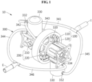
- FIG 1 is a perspective view of an integrated hybrid power apparatus 10 according to an example embodiment.
- FIG 2 is an enlarged perspective view of a generator 100 and at least one engine 200 according to an example embodiment.
- FIG 3 is an exploded perspective view of the generator 100 and the engine 200 according to an example embodiment.
- the integrated hybrid power apparatus 10 which may be provided in a flying body, includes the generator 100, the engine 200, and a cooler 300.
- the generator 100 includes a stator 110 and a rotor 120 that include a magnetic substance.
- the stator 110 of the integrated hybrid power apparatus 10 may be disposed on the outside of the rotor 120.
- the stator 110 may be disposed on the inside of the rotor 120 as needed. That is, the disposition of the stator 110 and the rotor 120 may vary, and not be limited to an example described in the foregoing.
- the stator 110 is provided in a doughnut shape in which a plurality of electromagnets or magnetic substances (e.g., magnets) with an armature coil being wound around a groove of an iron core are disposed in a circumferential direction.
- the stator 110 has a space in which a generator water jacket 320 is to be disposed.
- the stator 110 has a center portion through which a drive shaft S passes.
- the rotor 120 is provided in a cylindrical shape that surrounds the stator 110, in which a plurality of electromagnets or magnetic substances (e.g., magnets) with an armature coil being wound around an iron core are disposed in a circumferential direction.
- the rotor 120 is connected to the drive shaft S in a center portion (or centrifugal portion) of the rotor 120 and configured to directly receive mechanical energy of the engine 200 through the drive shaft S.
- the generator 100 may be a device configured to convert mechanical energy to electrical energy. While the rotor 120 is rotating by receiving mechanical energy of the engine 200, the rotor 120 may generate electrical energy or output electric power along with the stator 110 according to the Faraday's law of electromagnetic induction. There may be a gap between the stator 110 and the rotor 120. The generator 100 may output and produce electric power and start the engine 200. Thus, an additional starting unit for the engine 200 may not be required. In addition, the rotor 120 may perform a flywheel function through the rotation. Thus, the rotor 120 may store or emit rotational energy, and allow the engine 200 to operate stably.
- the engine 200 is disposed adjacent to the generator 100, and may include a single cylinder or a plurality of cylinders. Alternatively, the engine 200 includes a first engine 210 and a second engine 220 disposed on both sides of the generator 100.
- the engine 200 may be embodied as a single-cylinder or multi-cylinder reciprocating engine.
- the cylinder of the engine 200 is disposed adjacent to the generator 100, and may thus reduce an unnecessary weight or volume.
- the engine 200 may include a third engine and a fourth engine, in addition to the first engine 210 and the second engine 220.
- the engine 200 may include further engines.
- the first engine 210 and the second engine 220 may form point symmetry by being disposed adjacent to both sides on a central axis of the generator 100, and thus facilitate weight balance and reduce vibration. That is, such symmetrical disposition of a plurality of engines may induce mechanical balance and reduce an unnecessary force or vibration, thereby contributing to control.
- Each of the first engine 210 and the second engine 220 includes a cylinder.
- each of the first engine 210 and the second engine 220 may include a piston, a connecting rod, a crank main journal, a crankpin, a counterbalance, and a crankcase.
- the first engine 210 and the second engine 220 are disposed on both sides of the generator 100, and connected to the drive shaft S disposed at the center of the rotor 120 of the generator 100.
- a stator mount T is mounted on one side surface outside a crankcase disposed under the cylinder of the first engine 210.
- a stator connecting member C is mounted on one side surface of the generator water jacket 320 on an inner side of the stator 110 of the generator 100.
- the stator mount T and the stator connecting member C may be connected to each other to tightly connect the engine 200 and the generator 100.
- an engine mount M is provided on another side surface outside the crankcase of the engine 200, and may be provided in a fuselage of a flying body. As necessary, the engine mount M may be provided in one of the first engine 210 and the second engine 220.
- the generator 100 may be disposed at the center of the engine 200, and the generator 100 and the engine 200 may be connected thereto.
- the generator 100 may transfer mechanical energy that is converted from heat of the engine 200 according to the first law of thermodynamics to the rotor 120 of the generator 100 disposed at the center.
- the generator 100 may convert the mechanical energy to the electrical energy.
- a battery may be provided in the integrated hybrid power apparatus 10, and the generator 100 may convert electrical energy of the battery to mechanical energy to generate power.
- the generator 100 may also operate simultaneously, and thus a greater amount of power (e.g., torque) may be generated. That is, the generator 100 may be used as a motor.
- the generator 100 may generate power (e.g., torque) to start the engine 200.
- the generator 100 may generate power regardless of whether the engine 200 operates or not.
- cooler 300 of the integrated hybrid power apparatus 10 will be described in detail with reference to FIGS. 4A through 6 .
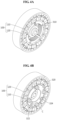
- FIG 4A is a perspective view of the generator 100 and a cooling fin 310 according to an example embodiment
- FIG 4B is a perspective view of the generator 100 and the generator water jacket 320 according to an example embodiment.
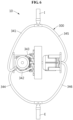
- FIG 5 is a cross-sectional view of the generator 100, the cooling fin 310, and the generator water jacket 320 according to an example embodiment.
- FIG 6 is a top view of the integrated hybrid power apparatus 10 according to an example embodiment.
- the cooler 300 includes the cooling fin 310, the generator water jacket 320, a cylinder water jacket 330, a first piping 341, a second piping 342, a third piping 343, a fourth piping 344, a fifth piping 345, and a sixth piping 346.
- the cooler 300 may perform, as a cooling method, water-cooling that allows a coolant to circulate in the generator 100 and the engine 200 to cool the generator 100 and the engine 200.
- air-cooling that uses gas as a cooling medium may also be used as the cooling method.
- the cooling method and the cooling medium are not limited to what is described in the foregoing.
- the cooling fin 310 protrudes to an inner side of the stator 110 through heat conduction from the stator 110 and may be provided as a plurality of cooling fins at an interval in a circumferential direction.
- the cooling fin 310 may be provided as a plurality of cooling fins at an interval in an axial direction to increase a heat transfer area of the stator 110.
- the cooling fin 310 may be formed selectively on one side of the stator 110 or the rotor 120.
- the generator water jacket 320 is disposed on an inner side of the stator 110 and may be provided in a doughnut-shaped tubular form of which a cross section is a quadrangle and that surrounds the cooling fin 310. As the generator water jacket 320 surrounds the cooling fin 310, the generator water jacket 320 may form a coolant flow path inside through which a coolant flows.
- the generator water jacket 320 includes a coolant inlet port 322 and a coolant outlet port 324 on an outer side of the generator water jacket 320. The coolant inlet port 322 and the coolant outlet port 324 may induce a flow of the coolant.
- the generator water jacket 320 may be formed selectively on one side of the stator 110 or the rotor 120.
- the cylinder water jacket 330 is formed inside the cylinder of the engine 200 and forms a coolant flow path.
- the cylinder water jacket 330 includes a coolant inlet port 332 and a coolant outlet port 334.
- the cylinder water jacket 330 inside the cylinder of the first engine 210 further includes a port that induces the coolant discharged from the generator water jacket 320, in addition to the coolant inlet port 332 and the coolant outlet port 334.
- Each of the coolant inlet port 332 and the coolant outlet port 334 of the cylinder water jacket 330 may be a single port or a plurality of ports.
- the coolant inlet port 332 of the cylinder water jacket 330 of the first engine 210 and the coolant inlet port 322 of the generator water jacket 320 are connected to a coolant inlet I.
- the coolant outlet port 324 of the generator water jacket 320 is connected to the cylinder water jacket 330 of the first engine 210.
- the coolant outlet port 334 of the cylinder water jacket 330 of the first engine 210 is connected to a coolant outlet E.
- the coolant inlet port 332 of the cylinder water jacket 330 of the second engine 220 is connected to the coolant inlet I
- the coolant outlet port 334 of the cylinder water jacket 330 of the second engine 220 is connected to the coolant outlet E.
- the coolant fed to the coolant inlet I is to be fed by being divided into the first piping 341 and the fifth piping 345.
- the first piping 341 has one end that is connected to the cylinder water jacket 330 of the first engine 210 to feed the coolant to the cylinder water jacket 330 of the first engine 210.
- the second piping 342 has one end that is connected to the first piping 341, and another end that is connected to the coolant inlet port 322 of the generator water jacket 320. Although the one end of the second piping 342 is connected to one side of the first piping 341, the second piping 342 may be connected directly to the coolant inlet I.
- the third piping 343 has one end that is connected to the coolant outlet port 324 of the generator water jacket 320, and another end that is connected to the cylinder water jacket 330 of the first engine 210.
- the third piping 343 may be connected directly to the coolant outlet E.
- the fourth piping 344 has one end that is connected to the cylinder water jacket 330 of the first engine 210 to allow the coolant to be discharged from the cylinder water jacket 330 of the first engine 210.
- the discharged coolant may flow out from the coolant outlet E.
- the coolant may cool the first engine 210 and the generator 100 while passing through the first piping 341, the second piping 342, the third piping 343, and the fourth piping 344 after being fed to the coolant inlet I.
- the coolant fed to the coolant inlet I may be fed to the fifth piping 345 through the divided pipings.
- the fifth piping 345 has one end that is connected to the cylinder water jacket 330 of the second engine 220 to feed the coolant to the cylinder water jacket 330 of the second engine 220, and another end that is connected directly to the coolant inlet I.
- the sixth piping 346 has one end that is connected to the cylinder water jacket 330 of the second engine 220 to allow the coolant to be discharged from the cylinder water jacket 330 of the second engine 220, and another end that is connected to the coolant outlet E such that the discharged coolant may flow out from the coolant outlet E.
- the coolant may cool the second engine 220 while passing through the fifth piping 345 and the sixth piping 346 after being fed to the coolant inlet I.
- the cooler 300 connected to the generator 100 and the engine 200 may be provided in an integral water-cooling type, and thus be more simplified in structure.
- the integrated hybrid power apparatus 10 may have a reduced weight or volume with the simplified structure, and thus operate more effectively.
- a heat transfer coefficient may be higher in water-cooling than in air-cooling, and a heat transfer speed may also be higher in water-cooling than in air-cooling.
- water-cooling may be more effective in cooling than air-cooling.
- the efficiency of the generator 100 and the engine 200 of the integrated hybrid power apparatus 10 may increase by the cooler 300 that is provided in the integral water-cooling type.
- the integrated hybrid power apparatus 10 may be provided in a flying body such as, for example, a drone, and be used for wherever power is needed according to a purpose.
- the cooler 300 configured to cool the generator 100 and the engine 200 is provided in an integral water-cooling type, and may thus simplify a power system as a whole and minimize a cooling loss.
- the rotor 120 of the generator 100 of the integrated hybrid power apparatus 10 may operate as a flywheel, and thus enable a stable operation.
- the engine mount M that is structurally stable and the stator mount T of the generator 100 are applied, and thus may reduce vibration of the generator 100 and the engine 200 and improve overall performance.
- the overall size reduction and the weight lightening may reduce total weight and vibration, thereby enabling an effective operation.
- an integrated hybrid power apparatus may simplify an overall engine-generator driving system as it is provided in an integral form in which a water-cooling reciprocating engine and a water-cooling generator are integrated.
- an integrated hybrid power apparatus may operate an integrated water-cooling system, and thus simplify a cooling device and minimize a cooling loss.
- an integrated hybrid power apparatus may be reduced in size and weight, and thus reduce total weight and vibration and enable an effective operation.
- an integrated hybrid power apparatus may enable a stable operation as a rotor of a generator operates as a flywheel.
Landscapes
- Engineering & Computer Science (AREA)
- Mechanical Engineering (AREA)
- Chemical & Material Sciences (AREA)
- Combustion & Propulsion (AREA)
- General Engineering & Computer Science (AREA)
- Power Engineering (AREA)
- Aviation & Aerospace Engineering (AREA)
- Physics & Mathematics (AREA)
- Geometry (AREA)
- Thermal Sciences (AREA)
- Motor Or Generator Cooling System (AREA)
- Connection Of Motors, Electrical Generators, Mechanical Devices, And The Like (AREA)
Claims (8)
- Integrierte hybride Antriebseinrichtung (10) für einen Flugkörper, umfassend:einen Generator (100), der einen Stator (110) und einen Rotor (120) umfasst, wobei der Rotor an einer Außenseite des Stators angeordnet ist;mindestens einen Motor (200), der neben dem Generator angeordnet ist und einen Zylinder umfasst, wobei der mindestens eine Motor zum Antrieb des Generators konfiguriert ist; undeinen Kühler (300), der zum Kühlen des Generators und des Motors konfiguriert ist, wobei der Kühler eine Wasserkühlung durchführt, wodurch ein Kühlmittel in dem Generator und dem Motor zirkulieren kann;wobei die integrierte hybride Antriebseinrichtung (10) dadurch gekennzeichnet ist, dass der Kühler Folgendes umfasst:eine Kühlrippe (310), die an einer Innenseite des Stators hervorsteht; undeinen Generatorwassermantel (320), der so konfiguriert ist, dass er die Kühlrippe auf der Innenseite des Stators umgibt und im Inneren einen Kühlmittelströmungsweg bildet.
- Integrierte hybride Antriebseinrichtung nach Anspruch 1, wobei der Generatorwassermantel eine Kühlmitteleinlassöffnung (322) und eine Kühlmittelauslassöffnung (324) umfasst,
wobei die Kühlmitteleinlassöffnung und die Kühlmittelauslassöffnung so konfiguriert sind, dass sie das Kühlmittel zum Fließen bringen. - Integrierte hybride Antriebseinrichtung nach Anspruch 2, wobei der Kühler einen Zylinderwassermantel (330) umfasst, der im Inneren des Zylinders des Motors ausgebildet ist und so konfiguriert ist, dass er einen Kühlmittelströmungsweg bildet,
wobei der Zylinderwassermantel eine Kühlmitteleinlassöffnung (332) und eine Kühlmittelauslassöffnung (334) umfasst,wobei die Kühlmitteleinlassöffnung des Zylinderwassermantels und die Kühlmitteleinlassöffnung des Generatorwassermantels mit einem Kühlmitteleinlass (I) verbunden sind,wobei die Kühlmittelauslassöffnung des Generatorwassermantels auf einer Seite mit dem Zylinderwassermantel verbunden ist, unddie Kühlmittelauslassöffnung des Zylinderwassermantels mit einem Kühlmittelauslass verbunden ist. - Integrierte hybride Antriebseinrichtung nach Anspruch 1, wobei der Kühler Folgendes umfasst:eine erste Rohrleitung (341), deren eines Ende mit einem Zylinderwassermantel (330) verbunden ist, um das Kühlmittel dem Zylinderwassermantel zuzuführen;eine zweite Rohrleitung (342), deren eines Ende mit der ersten Rohrleitung verbunden ist und deren anderes Ende mit einer Kühlmitteleinlassöffnung (322) des Generatorwassermantels verbunden ist;eine dritte Rohrleitung (343), deren eines Ende mit einer Kühlmittelauslassöffnung (324) des Generatorwassermantels verbunden ist und deren anderes Ende mit dem Zylinderwassermantel verbunden ist; undeine vierte Rohrleitung (344), deren eines Ende mit dem Zylinderwassermantel verbunden ist, damit das Kühlmittel aus dem Zylinderwassermantel abgeleitet werden kann.
- Integrierte hybride Antriebseinrichtung nach Anspruch 1, wobeider Stator eine magnetische Substanz umfasst;der Rotor eine magnetische Substanz umfasst;der mindestens eine Motor ein erster Motor (210) ist; undder mindestens eine Motor weiter einen zweiten Motor (220) umfasst, wobei der erste Motor und der zweite Motor auf beiden Seiten des Generators angeordnet sind, und wobei der erste Motor und der zweite Motor symmetrisch in Bezug auf den Generator angeordnet sind.
- Integrierte hybride Antriebseinrichtung nach Anspruch 5, wobei der Stator an einer Innenseite des Rotors angeordnet ist und der Rotor an einer Außenseite des Stators angeordnet ist,
und
der Rotor so konfiguriert ist, dass er eine Schwungradfunktion durch Erzeugung elektrischer Leistung und Drehung ausführt. - Integrierte hybride Antriebseinrichtung nach Anspruch 5, wobei:
der Kühler ein Kühlmittel umfasst, das im Generator, im ersten Motor und im zweiten Motor zirkuliert,
wobei der Kühler weiter einen Zylinderwassermantel (330) umfasst, der in einem Zylinder des ersten Motors oder des zweiten Motors ausgebildet ist und so konfiguriert ist, dass er einen Kühlmittelströmungsweg bildet. - Integrierte hybride Antriebseinrichtung nach Anspruch 7, wobei der Kühler Folgendes umfasst:eine erste Rohrleitung (341), deren eines Ende mit dem Zylinderwassermantel des ersten Motors verbunden ist, um das Kühlmittel dem Zylinderwassermantel des ersten Motors zuzuführen;eine zweite Rohrleitung (342), deren eines Ende mit der ersten Rohrleitung verbunden ist und deren anderes Ende mit einer Kühlmitteleinlassöffnung (322) des Generatorwassermantels verbunden ist;eine dritte Rohrleitung (343), deren eines Ende mit einer Kühlmittelauslassöffnung (324) des Generatorwassermantels verbunden ist und deren anderes Ende mit dem Zylinderwassermantel des ersten Motors verbunden ist;eine vierte Rohrleitung (344), deren eines Ende mit dem Zylinderwassermantel des ersten Motors verbunden ist, damit das Kühlmittel aus dem Zylinderwassermantel des ersten Motors abgeleitet werden kann;eine fünfte Rohrleitung (345), deren eines Ende mit einem Zylinderwassermantel des zweiten Motors verbunden ist, um das Kühlmittel dem Zylinderwassermantel des zweiten Motors zuzuführen; undeine sechste Rohrleitung (346), deren eines Ende mit dem Zylinderwassermantel des zweiten Motors verbunden ist, damit das Kühlmittel aus dem Zylinderwassermantel des zweiten Motors abgeleitet werden kann.
Applications Claiming Priority (1)
| Application Number | Priority Date | Filing Date | Title |
|---|---|---|---|
| KR1020190161764A KR102266898B1 (ko) | 2019-12-06 | 2019-12-06 | 일체형 하이브리드 동력장치 |
Publications (2)
| Publication Number | Publication Date |
|---|---|
| EP3832087A1 EP3832087A1 (de) | 2021-06-09 |
| EP3832087B1 true EP3832087B1 (de) | 2023-12-20 |
Family
ID=71016414
Family Applications (1)
| Application Number | Title | Priority Date | Filing Date |
|---|---|---|---|
| EP20178497.2A Active EP3832087B1 (de) | 2019-12-06 | 2020-06-05 | Integrierte hybrid-stromanlage |
Country Status (3)
| Country | Link |
|---|---|
| US (1) | US11339706B2 (de) |
| EP (1) | EP3832087B1 (de) |
| KR (1) | KR102266898B1 (de) |
Families Citing this family (3)
| Publication number | Priority date | Publication date | Assignee | Title |
|---|---|---|---|---|
| KR102549054B1 (ko) | 2022-06-23 | 2023-06-30 | 김영근 | 도막 방수제를 사용한 복합방수 시공방법 |
| CN115680872A (zh) * | 2022-10-27 | 2023-02-03 | 重庆隆鑫发动机有限公司 | 一种发动机 |
| KR102734626B1 (ko) * | 2022-11-18 | 2024-11-27 | 한국항공우주연구원 | 동력 장치 |
Family Cites Families (8)
| Publication number | Priority date | Publication date | Assignee | Title |
|---|---|---|---|---|
| DE3128081A1 (de) * | 1981-04-10 | 1982-11-04 | Robert Bosch Gmbh, 7000 Stuttgart | Heizvorrichtung |
| US5040493A (en) * | 1990-12-20 | 1991-08-20 | Ford Motor Company | Automotive intake manifold with integral alternator |
| DE19846220C2 (de) * | 1998-10-07 | 2001-11-29 | Mannesmann Sachs Ag | Kühleinrichtung für eine elektrische Maschine eines Fahrzeugs |
| DE10065003A1 (de) * | 2000-12-23 | 2002-07-04 | Bosch Gmbh Robert | Kühlsystem für ein Kraftfahrzeug |
| US20040212273A1 (en) * | 2003-04-24 | 2004-10-28 | Gould Len Charles | Heat engine and generator set incorporating multiple generators for synchronizing and balancing |
| KR20110074346A (ko) | 2009-12-24 | 2011-06-30 | 현대모비스 주식회사 | 브레이크용 펌프 |
| US8631885B2 (en) * | 2010-12-17 | 2014-01-21 | Leo Oriet | Multi-use dual-engine, variable-power drive |
| KR101797011B1 (ko) * | 2016-06-14 | 2017-11-13 | 주식회사 에이치앤티 | 소형 항공기용 엔진 발전기 및 이를 장착한 드론 |
-
2019
- 2019-12-06 KR KR1020190161764A patent/KR102266898B1/ko active Active
-
2020
- 2020-06-05 EP EP20178497.2A patent/EP3832087B1/de active Active
- 2020-06-22 US US16/908,565 patent/US11339706B2/en active Active
Also Published As
| Publication number | Publication date |
|---|---|
| US20210172368A1 (en) | 2021-06-10 |
| US11339706B2 (en) | 2022-05-24 |
| EP3832087A1 (de) | 2021-06-09 |
| KR102266898B1 (ko) | 2021-06-21 |
| KR20210072206A (ko) | 2021-06-17 |
Similar Documents
| Publication | Publication Date | Title |
|---|---|---|
| EP3832087B1 (de) | Integrierte hybrid-stromanlage | |
| US11303174B2 (en) | Rotor for an electric machine | |
| US10038355B2 (en) | Electric machine having rotor and stator cooling assembly | |
| US8269383B2 (en) | Electric machine cooling system and method | |
| EP0761982B1 (de) | Lüftereinheit | |
| US20060043801A1 (en) | Liquid cooled switched reluctance electric machine | |
| EP3244033A1 (de) | Turbolader | |
| CN111200335A (zh) | 用于电机的温度控制组件 | |
| KR20130110147A (ko) | 전기 기계 냉각 시스템 및 방법 | |
| US11996760B2 (en) | Aircraft electric motor having a stator heat pipe cooling scheme | |
| US20230327531A1 (en) | Aircraft electric motor | |
| US20230076200A1 (en) | Rotor Arrangement, Electric Propulsion Motor Arrangement, Vehicle, Set of Rotors for Electric Motors | |
| CN105162288B (zh) | 一种油内循环冷却电机 | |
| CN119891674B (zh) | 一种新能源汽车永磁同步电机 | |
| KR101846876B1 (ko) | 파워트레인 | |
| CN110620478A (zh) | 用于旋转电机的冷却装置和用于驱动车辆的旋转电机 | |
| JP2009153375A (ja) | 誘導型内部冷却を有する電気モータ | |
| JP2012223003A (ja) | ハイブリッド建設機械 | |
| CN222802691U (zh) | 一种内置轴流式风扇的无刷励磁机冷却结构 | |
| EP4614773A1 (de) | E-maschine mit flüssigkeitsgekühlten statorwickelschlitzen und gasabzugskanälen | |
| US20250192626A1 (en) | Electric motor stator tooth cooling | |
| CN102882302B (zh) | 电机模块冷却系统和方法 | |
| US12494699B2 (en) | Integrated electric motor and thermal management system | |
| US20250253730A1 (en) | Electric machine with cooling channel loops for stator magnetic poles | |
| JPS5875462A (ja) | リタ−ダの冷却装置 |
Legal Events
| Date | Code | Title | Description |
|---|---|---|---|
| PUAI | Public reference made under article 153(3) epc to a published international application that has entered the european phase |
Free format text: ORIGINAL CODE: 0009012 |
|
| STAA | Information on the status of an ep patent application or granted ep patent |
Free format text: STATUS: REQUEST FOR EXAMINATION WAS MADE |
|
| 17P | Request for examination filed |
Effective date: 20200605 |
|
| AK | Designated contracting states |
Kind code of ref document: A1 Designated state(s): AL AT BE BG CH CY CZ DE DK EE ES FI FR GB GR HR HU IE IS IT LI LT LU LV MC MK MT NL NO PL PT RO RS SE SI SK SM TR |
|
| REG | Reference to a national code |
Ref legal event code: R079 Free format text: PREVIOUS MAIN CLASS: F02B0073000000 Ipc: H02K0001279100 Ref country code: DE Ref legal event code: R079 Ref document number: 602020022951 Country of ref document: DE Free format text: PREVIOUS MAIN CLASS: F02B0073000000 Ipc: H02K0001279100 |
|
| GRAP | Despatch of communication of intention to grant a patent |
Free format text: ORIGINAL CODE: EPIDOSNIGR1 |
|
| STAA | Information on the status of an ep patent application or granted ep patent |
Free format text: STATUS: GRANT OF PATENT IS INTENDED |
|
| RIC1 | Information provided on ipc code assigned before grant |
Ipc: F02B 63/04 20060101ALI20230627BHEP Ipc: F02B 73/00 20060101ALI20230627BHEP Ipc: F01P 3/02 20060101ALI20230627BHEP Ipc: F01P 3/12 20060101ALI20230627BHEP Ipc: H02K 9/197 20060101ALI20230627BHEP Ipc: H02K 1/2791 20220101AFI20230627BHEP |
|
| INTG | Intention to grant announced |
Effective date: 20230712 |
|
| GRAS | Grant fee paid |
Free format text: ORIGINAL CODE: EPIDOSNIGR3 |
|
| GRAA | (expected) grant |
Free format text: ORIGINAL CODE: 0009210 |
|
| STAA | Information on the status of an ep patent application or granted ep patent |
Free format text: STATUS: THE PATENT HAS BEEN GRANTED |
|
| AK | Designated contracting states |
Kind code of ref document: B1 Designated state(s): AL AT BE BG CH CY CZ DE DK EE ES FI FR GB GR HR HU IE IS IT LI LT LU LV MC MK MT NL NO PL PT RO RS SE SI SK SM TR |
|
| REG | Reference to a national code |
Ref country code: GB Ref legal event code: FG4D |
|
| REG | Reference to a national code |
Ref country code: DE Ref legal event code: R096 Ref document number: 602020022951 Country of ref document: DE |
|
| REG | Reference to a national code |
Ref country code: CH Ref legal event code: EP |
|
| REG | Reference to a national code |
Ref country code: IE Ref legal event code: FG4D |
|
| PG25 | Lapsed in a contracting state [announced via postgrant information from national office to epo] |
Ref country code: GR Free format text: LAPSE BECAUSE OF FAILURE TO SUBMIT A TRANSLATION OF THE DESCRIPTION OR TO PAY THE FEE WITHIN THE PRESCRIBED TIME-LIMIT Effective date: 20240321 |
|
| REG | Reference to a national code |
Ref country code: LT Ref legal event code: MG9D |
|
| PG25 | Lapsed in a contracting state [announced via postgrant information from national office to epo] |
Ref country code: LT Free format text: LAPSE BECAUSE OF FAILURE TO SUBMIT A TRANSLATION OF THE DESCRIPTION OR TO PAY THE FEE WITHIN THE PRESCRIBED TIME-LIMIT Effective date: 20231220 |
|
| REG | Reference to a national code |
Ref country code: NL Ref legal event code: MP Effective date: 20231220 |
|
| PG25 | Lapsed in a contracting state [announced via postgrant information from national office to epo] |
Ref country code: ES Free format text: LAPSE BECAUSE OF FAILURE TO SUBMIT A TRANSLATION OF THE DESCRIPTION OR TO PAY THE FEE WITHIN THE PRESCRIBED TIME-LIMIT Effective date: 20231220 |
|
| PG25 | Lapsed in a contracting state [announced via postgrant information from national office to epo] |
Ref country code: LT Free format text: LAPSE BECAUSE OF FAILURE TO SUBMIT A TRANSLATION OF THE DESCRIPTION OR TO PAY THE FEE WITHIN THE PRESCRIBED TIME-LIMIT Effective date: 20231220 Ref country code: GR Free format text: LAPSE BECAUSE OF FAILURE TO SUBMIT A TRANSLATION OF THE DESCRIPTION OR TO PAY THE FEE WITHIN THE PRESCRIBED TIME-LIMIT Effective date: 20240321 Ref country code: FI Free format text: LAPSE BECAUSE OF FAILURE TO SUBMIT A TRANSLATION OF THE DESCRIPTION OR TO PAY THE FEE WITHIN THE PRESCRIBED TIME-LIMIT Effective date: 20231220 Ref country code: ES Free format text: LAPSE BECAUSE OF FAILURE TO SUBMIT A TRANSLATION OF THE DESCRIPTION OR TO PAY THE FEE WITHIN THE PRESCRIBED TIME-LIMIT Effective date: 20231220 Ref country code: BG Free format text: LAPSE BECAUSE OF FAILURE TO SUBMIT A TRANSLATION OF THE DESCRIPTION OR TO PAY THE FEE WITHIN THE PRESCRIBED TIME-LIMIT Effective date: 20240320 |
|
| REG | Reference to a national code |
Ref country code: AT Ref legal event code: MK05 Ref document number: 1643309 Country of ref document: AT Kind code of ref document: T Effective date: 20231220 |
|
| PG25 | Lapsed in a contracting state [announced via postgrant information from national office to epo] |
Ref country code: NL Free format text: LAPSE BECAUSE OF FAILURE TO SUBMIT A TRANSLATION OF THE DESCRIPTION OR TO PAY THE FEE WITHIN THE PRESCRIBED TIME-LIMIT Effective date: 20231220 |
|
| PG25 | Lapsed in a contracting state [announced via postgrant information from national office to epo] |
Ref country code: SE Free format text: LAPSE BECAUSE OF FAILURE TO SUBMIT A TRANSLATION OF THE DESCRIPTION OR TO PAY THE FEE WITHIN THE PRESCRIBED TIME-LIMIT Effective date: 20231220 Ref country code: RS Free format text: LAPSE BECAUSE OF FAILURE TO SUBMIT A TRANSLATION OF THE DESCRIPTION OR TO PAY THE FEE WITHIN THE PRESCRIBED TIME-LIMIT Effective date: 20231220 Ref country code: NO Free format text: LAPSE BECAUSE OF FAILURE TO SUBMIT A TRANSLATION OF THE DESCRIPTION OR TO PAY THE FEE WITHIN THE PRESCRIBED TIME-LIMIT Effective date: 20240320 Ref country code: NL Free format text: LAPSE BECAUSE OF FAILURE TO SUBMIT A TRANSLATION OF THE DESCRIPTION OR TO PAY THE FEE WITHIN THE PRESCRIBED TIME-LIMIT Effective date: 20231220 Ref country code: LV Free format text: LAPSE BECAUSE OF FAILURE TO SUBMIT A TRANSLATION OF THE DESCRIPTION OR TO PAY THE FEE WITHIN THE PRESCRIBED TIME-LIMIT Effective date: 20231220 Ref country code: HR Free format text: LAPSE BECAUSE OF FAILURE TO SUBMIT A TRANSLATION OF THE DESCRIPTION OR TO PAY THE FEE WITHIN THE PRESCRIBED TIME-LIMIT Effective date: 20231220 |
|
| PG25 | Lapsed in a contracting state [announced via postgrant information from national office to epo] |
Ref country code: IS Free format text: LAPSE BECAUSE OF FAILURE TO SUBMIT A TRANSLATION OF THE DESCRIPTION OR TO PAY THE FEE WITHIN THE PRESCRIBED TIME-LIMIT Effective date: 20240420 |
|
| PG25 | Lapsed in a contracting state [announced via postgrant information from national office to epo] |
Ref country code: AT Free format text: LAPSE BECAUSE OF FAILURE TO SUBMIT A TRANSLATION OF THE DESCRIPTION OR TO PAY THE FEE WITHIN THE PRESCRIBED TIME-LIMIT Effective date: 20231220 |
|
| PG25 | Lapsed in a contracting state [announced via postgrant information from national office to epo] |
Ref country code: SK Free format text: LAPSE BECAUSE OF FAILURE TO SUBMIT A TRANSLATION OF THE DESCRIPTION OR TO PAY THE FEE WITHIN THE PRESCRIBED TIME-LIMIT Effective date: 20231220 |
|
| PG25 | Lapsed in a contracting state [announced via postgrant information from national office to epo] |
Ref country code: SM Free format text: LAPSE BECAUSE OF FAILURE TO SUBMIT A TRANSLATION OF THE DESCRIPTION OR TO PAY THE FEE WITHIN THE PRESCRIBED TIME-LIMIT Effective date: 20231220 Ref country code: SK Free format text: LAPSE BECAUSE OF FAILURE TO SUBMIT A TRANSLATION OF THE DESCRIPTION OR TO PAY THE FEE WITHIN THE PRESCRIBED TIME-LIMIT Effective date: 20231220 Ref country code: RO Free format text: LAPSE BECAUSE OF FAILURE TO SUBMIT A TRANSLATION OF THE DESCRIPTION OR TO PAY THE FEE WITHIN THE PRESCRIBED TIME-LIMIT Effective date: 20231220 Ref country code: IS Free format text: LAPSE BECAUSE OF FAILURE TO SUBMIT A TRANSLATION OF THE DESCRIPTION OR TO PAY THE FEE WITHIN THE PRESCRIBED TIME-LIMIT Effective date: 20240420 Ref country code: EE Free format text: LAPSE BECAUSE OF FAILURE TO SUBMIT A TRANSLATION OF THE DESCRIPTION OR TO PAY THE FEE WITHIN THE PRESCRIBED TIME-LIMIT Effective date: 20231220 Ref country code: AT Free format text: LAPSE BECAUSE OF FAILURE TO SUBMIT A TRANSLATION OF THE DESCRIPTION OR TO PAY THE FEE WITHIN THE PRESCRIBED TIME-LIMIT Effective date: 20231220 |
|
| PG25 | Lapsed in a contracting state [announced via postgrant information from national office to epo] |
Ref country code: PL Free format text: LAPSE BECAUSE OF FAILURE TO SUBMIT A TRANSLATION OF THE DESCRIPTION OR TO PAY THE FEE WITHIN THE PRESCRIBED TIME-LIMIT Effective date: 20231220 Ref country code: PT Free format text: LAPSE BECAUSE OF FAILURE TO SUBMIT A TRANSLATION OF THE DESCRIPTION OR TO PAY THE FEE WITHIN THE PRESCRIBED TIME-LIMIT Effective date: 20240422 |
|
| PG25 | Lapsed in a contracting state [announced via postgrant information from national office to epo] |
Ref country code: PT Free format text: LAPSE BECAUSE OF FAILURE TO SUBMIT A TRANSLATION OF THE DESCRIPTION OR TO PAY THE FEE WITHIN THE PRESCRIBED TIME-LIMIT Effective date: 20240422 Ref country code: PL Free format text: LAPSE BECAUSE OF FAILURE TO SUBMIT A TRANSLATION OF THE DESCRIPTION OR TO PAY THE FEE WITHIN THE PRESCRIBED TIME-LIMIT Effective date: 20231220 |
|
| REG | Reference to a national code |
Ref country code: DE Ref legal event code: R097 Ref document number: 602020022951 Country of ref document: DE |
|
| PG25 | Lapsed in a contracting state [announced via postgrant information from national office to epo] |
Ref country code: DK Free format text: LAPSE BECAUSE OF FAILURE TO SUBMIT A TRANSLATION OF THE DESCRIPTION OR TO PAY THE FEE WITHIN THE PRESCRIBED TIME-LIMIT Effective date: 20231220 |
|
| PLBE | No opposition filed within time limit |
Free format text: ORIGINAL CODE: 0009261 |
|
| STAA | Information on the status of an ep patent application or granted ep patent |
Free format text: STATUS: NO OPPOSITION FILED WITHIN TIME LIMIT |
|
| PG25 | Lapsed in a contracting state [announced via postgrant information from national office to epo] |
Ref country code: SI Free format text: LAPSE BECAUSE OF FAILURE TO SUBMIT A TRANSLATION OF THE DESCRIPTION OR TO PAY THE FEE WITHIN THE PRESCRIBED TIME-LIMIT Effective date: 20231220 |
|
| PG25 | Lapsed in a contracting state [announced via postgrant information from national office to epo] |
Ref country code: SI Free format text: LAPSE BECAUSE OF FAILURE TO SUBMIT A TRANSLATION OF THE DESCRIPTION OR TO PAY THE FEE WITHIN THE PRESCRIBED TIME-LIMIT Effective date: 20231220 Ref country code: DK Free format text: LAPSE BECAUSE OF FAILURE TO SUBMIT A TRANSLATION OF THE DESCRIPTION OR TO PAY THE FEE WITHIN THE PRESCRIBED TIME-LIMIT Effective date: 20231220 |
|
| 26N | No opposition filed |
Effective date: 20240923 |
|
| PG25 | Lapsed in a contracting state [announced via postgrant information from national office to epo] |
Ref country code: MC Free format text: LAPSE BECAUSE OF FAILURE TO SUBMIT A TRANSLATION OF THE DESCRIPTION OR TO PAY THE FEE WITHIN THE PRESCRIBED TIME-LIMIT Effective date: 20231220 |
|
| REG | Reference to a national code |
Ref country code: CH Ref legal event code: PL |
|
| PG25 | Lapsed in a contracting state [announced via postgrant information from national office to epo] |
Ref country code: LU Free format text: LAPSE BECAUSE OF NON-PAYMENT OF DUE FEES Effective date: 20240605 |
|
| PG25 | Lapsed in a contracting state [announced via postgrant information from national office to epo] |
Ref country code: IE Free format text: LAPSE BECAUSE OF NON-PAYMENT OF DUE FEES Effective date: 20240605 |
|
| PG25 | Lapsed in a contracting state [announced via postgrant information from national office to epo] |
Ref country code: BE Free format text: LAPSE BECAUSE OF NON-PAYMENT OF DUE FEES Effective date: 20240630 Ref country code: CH Free format text: LAPSE BECAUSE OF NON-PAYMENT OF DUE FEES Effective date: 20240630 |
|
| PG25 | Lapsed in a contracting state [announced via postgrant information from national office to epo] |
Ref country code: FR Free format text: LAPSE BECAUSE OF NON-PAYMENT OF DUE FEES Effective date: 20240630 |
|
| PGFP | Annual fee paid to national office [announced via postgrant information from national office to epo] |
Ref country code: CZ Payment date: 20250312 Year of fee payment: 6 |
|
| PGFP | Annual fee paid to national office [announced via postgrant information from national office to epo] |
Ref country code: IT Payment date: 20250321 Year of fee payment: 6 |
|
| REG | Reference to a national code |
Ref country code: BE Ref legal event code: MM Effective date: 20240630 |
|
| PGFP | Annual fee paid to national office [announced via postgrant information from national office to epo] |
Ref country code: DE Payment date: 20250320 Year of fee payment: 6 |
|
| PGFP | Annual fee paid to national office [announced via postgrant information from national office to epo] |
Ref country code: GB Payment date: 20250407 Year of fee payment: 6 |
|
| PG25 | Lapsed in a contracting state [announced via postgrant information from national office to epo] |
Ref country code: CY Free format text: LAPSE BECAUSE OF FAILURE TO SUBMIT A TRANSLATION OF THE DESCRIPTION OR TO PAY THE FEE WITHIN THE PRESCRIBED TIME-LIMIT; INVALID AB INITIO Effective date: 20200605 |
|
| PG25 | Lapsed in a contracting state [announced via postgrant information from national office to epo] |
Ref country code: HU Free format text: LAPSE BECAUSE OF FAILURE TO SUBMIT A TRANSLATION OF THE DESCRIPTION OR TO PAY THE FEE WITHIN THE PRESCRIBED TIME-LIMIT; INVALID AB INITIO Effective date: 20200605 |