EP3832090B1 - Turbine à gaz pour des applications de centrale électrique avec du gaz combustible préchauffé et procédé de fonctionnement de cette turbine à gaz - Google Patents
Turbine à gaz pour des applications de centrale électrique avec du gaz combustible préchauffé et procédé de fonctionnement de cette turbine à gaz Download PDFInfo
- Publication number
- EP3832090B1 EP3832090B1 EP19213681.0A EP19213681A EP3832090B1 EP 3832090 B1 EP3832090 B1 EP 3832090B1 EP 19213681 A EP19213681 A EP 19213681A EP 3832090 B1 EP3832090 B1 EP 3832090B1
- Authority
- EP
- European Patent Office
- Prior art keywords
- fuel
- duct
- gas turbine
- stage
- air
- Prior art date
- Legal status (The legal status is an assumption and is not a legal conclusion. Google has not performed a legal analysis and makes no representation as to the accuracy of the status listed.)
- Active
Links
Images

Classifications
-
- F—MECHANICAL ENGINEERING; LIGHTING; HEATING; WEAPONS; BLASTING
- F02—COMBUSTION ENGINES; HOT-GAS OR COMBUSTION-PRODUCT ENGINE PLANTS
- F02C—GAS-TURBINE PLANTS; AIR INTAKES FOR JET-PROPULSION PLANTS; CONTROLLING FUEL SUPPLY IN AIR-BREATHING JET-PROPULSION PLANTS
- F02C7/00—Features, components parts, details or accessories, not provided for in, or of interest apart form groups F02C1/00 - F02C6/00; Air intakes for jet-propulsion plants
- F02C7/12—Cooling of plants
- F02C7/14—Cooling of plants of fluids in the plant, e.g. lubricant or fuel
- F02C7/141—Cooling of plants of fluids in the plant, e.g. lubricant or fuel of working fluid
-
- F—MECHANICAL ENGINEERING; LIGHTING; HEATING; WEAPONS; BLASTING
- F02—COMBUSTION ENGINES; HOT-GAS OR COMBUSTION-PRODUCT ENGINE PLANTS
- F02C—GAS-TURBINE PLANTS; AIR INTAKES FOR JET-PROPULSION PLANTS; CONTROLLING FUEL SUPPLY IN AIR-BREATHING JET-PROPULSION PLANTS
- F02C7/00—Features, components parts, details or accessories, not provided for in, or of interest apart form groups F02C1/00 - F02C6/00; Air intakes for jet-propulsion plants
- F02C7/12—Cooling of plants
- F02C7/14—Cooling of plants of fluids in the plant, e.g. lubricant or fuel
-
- F—MECHANICAL ENGINEERING; LIGHTING; HEATING; WEAPONS; BLASTING
- F02—COMBUSTION ENGINES; HOT-GAS OR COMBUSTION-PRODUCT ENGINE PLANTS
- F02C—GAS-TURBINE PLANTS; AIR INTAKES FOR JET-PROPULSION PLANTS; CONTROLLING FUEL SUPPLY IN AIR-BREATHING JET-PROPULSION PLANTS
- F02C3/00—Gas-turbine plants characterised by the use of combustion products as the working fluid
- F02C3/14—Gas-turbine plants characterised by the use of combustion products as the working fluid characterised by the arrangement of the combustion chamber in the plant
-
- F—MECHANICAL ENGINEERING; LIGHTING; HEATING; WEAPONS; BLASTING
- F02—COMBUSTION ENGINES; HOT-GAS OR COMBUSTION-PRODUCT ENGINE PLANTS
- F02C—GAS-TURBINE PLANTS; AIR INTAKES FOR JET-PROPULSION PLANTS; CONTROLLING FUEL SUPPLY IN AIR-BREATHING JET-PROPULSION PLANTS
- F02C7/00—Features, components parts, details or accessories, not provided for in, or of interest apart form groups F02C1/00 - F02C6/00; Air intakes for jet-propulsion plants
- F02C7/12—Cooling of plants
- F02C7/16—Cooling of plants characterised by cooling medium
- F02C7/18—Cooling of plants characterised by cooling medium the medium being gaseous, e.g. air
-
- F—MECHANICAL ENGINEERING; LIGHTING; HEATING; WEAPONS; BLASTING
- F02—COMBUSTION ENGINES; HOT-GAS OR COMBUSTION-PRODUCT ENGINE PLANTS
- F02C—GAS-TURBINE PLANTS; AIR INTAKES FOR JET-PROPULSION PLANTS; CONTROLLING FUEL SUPPLY IN AIR-BREATHING JET-PROPULSION PLANTS
- F02C7/00—Features, components parts, details or accessories, not provided for in, or of interest apart form groups F02C1/00 - F02C6/00; Air intakes for jet-propulsion plants
- F02C7/22—Fuel supply systems
- F02C7/224—Heating fuel before feeding to the burner
-
- F—MECHANICAL ENGINEERING; LIGHTING; HEATING; WEAPONS; BLASTING
- F02—COMBUSTION ENGINES; HOT-GAS OR COMBUSTION-PRODUCT ENGINE PLANTS
- F02C—GAS-TURBINE PLANTS; AIR INTAKES FOR JET-PROPULSION PLANTS; CONTROLLING FUEL SUPPLY IN AIR-BREATHING JET-PROPULSION PLANTS
- F02C7/00—Features, components parts, details or accessories, not provided for in, or of interest apart form groups F02C1/00 - F02C6/00; Air intakes for jet-propulsion plants
- F02C7/22—Fuel supply systems
- F02C7/228—Dividing fuel between various burners
-
- F—MECHANICAL ENGINEERING; LIGHTING; HEATING; WEAPONS; BLASTING
- F02—COMBUSTION ENGINES; HOT-GAS OR COMBUSTION-PRODUCT ENGINE PLANTS
- F02C—GAS-TURBINE PLANTS; AIR INTAKES FOR JET-PROPULSION PLANTS; CONTROLLING FUEL SUPPLY IN AIR-BREATHING JET-PROPULSION PLANTS
- F02C7/00—Features, components parts, details or accessories, not provided for in, or of interest apart form groups F02C1/00 - F02C6/00; Air intakes for jet-propulsion plants
- F02C7/22—Fuel supply systems
- F02C7/232—Fuel valves; Draining valves or systems
-
- F—MECHANICAL ENGINEERING; LIGHTING; HEATING; WEAPONS; BLASTING
- F23—COMBUSTION APPARATUS; COMBUSTION PROCESSES
- F23R—GENERATING COMBUSTION PRODUCTS OF HIGH PRESSURE OR HIGH VELOCITY, e.g. GAS-TURBINE COMBUSTION CHAMBERS
- F23R3/00—Continuous combustion chambers using liquid or gaseous fuel
- F23R3/28—Continuous combustion chambers using liquid or gaseous fuel characterised by the fuel supply
- F23R3/34—Feeding into different combustion zones
- F23R3/346—Feeding into different combustion zones for staged combustion
-
- F—MECHANICAL ENGINEERING; LIGHTING; HEATING; WEAPONS; BLASTING
- F23—COMBUSTION APPARATUS; COMBUSTION PROCESSES
- F23R—GENERATING COMBUSTION PRODUCTS OF HIGH PRESSURE OR HIGH VELOCITY, e.g. GAS-TURBINE COMBUSTION CHAMBERS
- F23R2900/00—Special features of, or arrangements for continuous combustion chambers; Combustion processes therefor
- F23R2900/03341—Sequential combustion chambers or burners
Definitions
- the present invention relates to the technical field of gas turbine assemblies (in the following only GT) for power plant applications.
- a GT compresses air, mixes the compressed air with fuel, ignites the mixture in a combustor and expands the hot gas in a turbine afterwards for the generation of mechanical work on the GT's shaft.
- the GT of the present application is equipped with a sequential combustion technology (preferably the applicant's sequential combustion technology), combusting fuel-air mixtures in two sequential stages.
- compressed air is mixed with fuel and combusted, generating a hot gas flow.
- fuel is injected into the hot gas, leading to a self-ignition of the fuel due to the hot ambient.
- the present invention solves the problem to shut-down the second stage and to operate the GT assembly, while the first stage is still in operation.
- a GT assembly comprises the following assemblies: compressor, combustor and turbine.
- the axial compressor is pressurizing air that is sucked into the compressor from the engine's environment. Compressed air is leaving the compressor at its exit into a fixed volume (called "plenum") from where the main flow is distributed to the combustor assembly and a part of the compressed air is used as cooling air.
- the combustor assembly comprises a plurality of combustor cans and burners, mixing the pressurized air with fuel (gas or oil) and igniting this mixture. Afterwards, the resulting hot gas is expanded through a turbine. Mechanical work performed by the hot gas flow on the turbine's blades, is translated into rotational energy due to the circumferential assembled blades to the GT's rotor.
- the Applicant's sequential combustion technology in its GTs This technology follows the principle of a re-heat step in the GT's thermodynamic cycle.
- the first and the second combustor are annular shaped and are physically separated by a stage of turbine blades, called high pressure turbine. Downstream the second combustor a second turbine unit is present (called low pressure turbine).
- This kind of GT is produced by the Applicant and is available on the market as "GT26".
- the GT is not provided with the high pressure turbine and the combustor assembly is realized in form of a plurality of can-combustors arranged as a ring around the rotor.
- Each can-combustor comprises a first stage and a second stage, arranged serially.
- this second kind of a GT is produced by the Applicant and is available on the market as "GT36".
- GT36 Those two examples of GT assemblies (GT26 and GT36) have been cited only as non-limiting examples wherein the present invention can be applied.
- the application of the present invention in a sequential can combustor GT may involves higher advantages.
- pre-heated fuel gas in the following only FG
- FG pre-heated fuel gas
- this pre-heated fuel in a GT also involves some problems to be solved. Due to the fuel's high temperature, it is not possible to use conventional soft seal valves along the fuel distribution lines. Therefore, in case of a pre-heated fuel, the fuel distribution lines has to be provided with metal-seat valves.
- a GT may be operated in a so called "first-stage only operation".
- the first stage of combustion is operated, only, and the valves arranged along the fuel distribution lines towards the second stage of combustion are driven to be closed.
- metal-seat valves are not a 100% tight and fuel leakage across those valves has to be expected. This leak can accumulate in the fuel distribution lines immediately upstream the second combustion stage, i.e. in the piping and fuel distribution system upstream the second stage burners.
- the presence of leaking FG in a shut-down combustion stage and the presence of potentially accumulating FG in the FG distribution system provides a risk to the safe operation of the GT assembly.
- EP2206966 discloses a gas turbine engine including a combustor having a first interior in which a first fuel is combustible, the first fuel including natural gas and/or a blend of natural gas and alternate gas receivable by a fuel circuit from an external source.
- a primary object of the present invention is to provide a new and inventive solution for overcoming the above problems, i.e. how to avoid undesired accumulation of leaked FG inside the fuel distribution lines, when a GT is used in first-stage only operation.
- the primary object of the present invention is to provide a GT according to claim 1 fed by pre-heated FG and a method for operating this GT according to claim 8.
- a GT that can be provided with the present invention is a GT for power plant comprising:
- this combustor assembly comprises a plurality of can combustors, wherein each can combustor comprises in series the first combustion stage and the second combustion stage.
- the first line of the fuel distribution system is configured for feeding all first combustion stages and the second line of the fuel distribution system is configured for feeding all second combustion stages.
- this source is configured for feeding a plurality of different kind of fuels; according to the present invention, the claimed pre-heated fuel is FG fed to a single duct and splitted into two lines downstream.
- the GT may be operated in a so called "first stage only operation mode", wherein the second stage of the combustor is switch-off and the second stage fuel distribution system's valves are driven to be closed.
- the fuel is pre-heated (between 250°C and 320°C, preferably at 300°C)
- the fuel distribution system's control valves are metal-seat valves and therefore, during the first stage only operation mode, fuel upstream those valves can leak across that metal-seat valves. Consequently, some pre-heated fuel can accumulate upstream the shut-down second combustion stage, in particular inside a duct (claimed first duct) acting as a collector for feeding the second burners.
- the GT moreover comprises a duct (claimed second duct) configured to be fed with cooled air and wherein this second duct is connected at one side to the first duct (where the leaked fuel is accumulated), generating a lean air-fuel mixture. Since the cooled air discloses a temperature (temperature between 320°C and 360°C, preferably at 340°C) lower than the auto-ignition temperature of the fuel, any undue ignition of the mixing media is avoided.
- the GT moreover comprises a control unit configured for selectively operating the GT in a first stage only mode and (in this case) for closing the valves of the second stage's fuel line.
- the feeding of the cooled air to the second duct is activated by the control unit only during the first stage only operation mode (preferably continuously during the first stage only operation mode).
- first and second duct we mean not necessary a single duct but also distribution lines comprising more than a duct.
- the GT comprises moreover a heat exchanger (maybe a so called Once Through Cooler or "OCT"), configured for cooling compressed air exiting from the compressor and for feeding this cooled air to the turbine for cooling purposes.
- a heat exchanger maybe a so called Once Through Cooler or "OCT"
- the second duct is a duct connected at the other side to the exit of the heat exchanger so that the cooled air fed in the second duct is part of the cooling air exiting from the heat exchanger.
- no additional source of purging gas for instance nitrogen
- cooling air fed in second duct air is also acting as purge air when switching of the combustor's second stage.
- the present invention may also be defined as a method for operating a GT for power plant fed by pre-heated fuel (i.e. FG).
- the method may comprise the steps of:
- step d) is performed so that the cooling air is also acting as purge air when switching off the second stage.
- FIG. 1 is a schematic view of an embodiment of a GT assembly for power plants with sequential combustion , suitable for being provided with the present invention.
- Figure 1 discloses a GT 1 having a rotor 6 defining an axis 2 and comprising in series along the main flow M:
- the GT 1 of figure 1 is a GT wherein the combustor section comprises in series a first combustion stage 9 and a second combustion stage 10, respectively fed with fuel by a first fuel distribution line 11 and a second fuel distribution line 12.
- the first and second fuel distribution lines 11 and 12 are fed by a common fuel supply 13.
- the fuel supply 13 is a fuel source configured for delivering at least one kind of fuel, i.e. a FG, wherein this fuel is a pre-heated fuel, i.e. a fuel pre-heated at least up to 300°C before being fed into the first and second fuel distribution lines 11 and 12.
- the reference 8 refers to a heat exchanger, preferably a OTC, fed by compressed air spilled from the compressed C and configured for cooling this air and for suppling this cooled air to the turbine 5 for cooling purposes.
- the kind of GT 1 as disclosed in figure 1 is particular useful for being implemented with the present invention, i.e. with minimal new components to be added in this assembly.
- FIG. 2 is an enlarged view of an embodiment of the combustor section 4 of figure 1 .
- figure 2 discloses a can combustor 4 of a plurality of can combustors 4 arranged as a ring around the turbine axis and forming the combustor section 4.
- Each can combustor 4 is housed in a relative portal hole of an outer casing 14 defining a plenum 15 where the compresses air are delivered by the compressor 3.
- Each can combustor 4 has an axis 16 and comprises in series along the main flow M a first combustor 9, and a second combustor 10.
- the first combustor 9 comprises a plurality of first burners 17 followed by a first combustion chamber 18.
- the second combustor 10 comprises a second burner assembly 19 followed by a second combustion chamber 20.
- the fuel is fed to the second burner 19 by a second fuel distribution line 12 extending in this case outside the combustor casing 21. Downstream the second combustion chamber 20, a transition duct 22 is present for guiding the hot gas toward the turbine 5.
- the second fuel distribution line 12 of figure 2 may be realized in form of a circular collector configured for feeding all can combustor second stage 10. As disclosed in figure 1 , the second fuel distribution line 12 is connected to a fuel source 13 feeding also the first fuel distribution line 11.
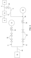
- FIG 3 is a schematic view of an example of a fuel feeding system of the combustor section of figures 1 and 2 .
- the fuel source 13 is configured for delivering a pre-heated fuel (preferably from 230°C to 300C°) in the first fuel distribution line 11 and in the second fuel distribution line 12, configured for feeding this fuel to the first combustion stage 9 and to the second 10 combustion stage of the GT 1, respectively, .
- Each line 11 12 of the fuel feeding system is provided with at least a valve, preferably a metal-seat valve due to the high temperature of the fuel.
- a duct 26 is present, preferably in form of a collector.
- the valves 24 25 along the second fuel distribution line 12 are driven to be closed for avoiding fuel being fed to the shut-down second combustion stage 10.
- valves 24, 25 are metal-seat valves (soft-seal valves cannot be used due to the high fuel temperature), fuel leakage can occur and therefore, some leaked fuel may accumulate in the duct 26 between the control valve 25 and the second combustion stage 10. In order to avoid any undesired ignition of this accumulated fuel in the duct 26 (in case of hot gas ingestion from the combustion chamber, ignition may occur immediately).
- cooled air is fed to this duct 26 (i.e. air having a temperature less than the auto ignition temperature of the fuel leakage, for instance no more than 340°C). Thereby, two effects are generated.
- the cooled air fed in the duct 26 is part of the cooling air exiting from the heat exchanger 8, in turn fed by compressed air and configured for generating cooling air to be supplied to the turbine 5. Since this heat exchanger 8 is already present in the GT assembly, for performing the present invention it is only necessary to provide a duct 27 (comprising at least a valves 28) connecting the exit of the heat exchanger 8 to the duct 26. Preferably, this feeding of cooled air to the duct 27 may be performed continuously during the first stage only operation mode.
Landscapes
- Engineering & Computer Science (AREA)
- Chemical & Material Sciences (AREA)
- Combustion & Propulsion (AREA)
- Mechanical Engineering (AREA)
- General Engineering & Computer Science (AREA)
- Air Supply (AREA)
- Engine Equipment That Uses Special Cycles (AREA)
Claims (12)
- Turbine à gaz pour une application en centrale électrique alimentée par du gaz combustible préchauffé ; la turbine à gaz (1) comprend :- un compresseur (3) pour comprimer l'air entrant ;- un ensemble de chambre de combustion séquentielle (4) configuré pour alimenter au moins un combustible dans l'air comprimé et générer un flux de gaz chaud ; dans lequel l'ensemble de chambre combustion (4) comprend en série un premier étage de combustion (9) et un second étage de combustion (10) ;- une turbine (5) configurée pour être entraînée par le gaz chaud pour effectuer un travail sur un rotor (6) ;- une source de combustible (13) configurée pour fournir du combustible préchauffé à un système de distribution de gaz combustible comprenant une première ligne (11) pour alimenter le premier étage de combustion (9) et une seconde ligne (12) pour alimenter le second étage de combustion (10) ; la seconde ligne (12) comprenant au moins une vanne d'arrêt amont (24) et au moins une vanne de commande aval (25) ; l'au moins une vanne d'arrêt amont (24) et l'au moins une vanne de commande aval (25) sont des soupapes à siège métallique ; entre l'au moins une vanne de commande aval (25) et le deuxième étage de combustion (10), un premier conduit (26) est présent, où le gaz combustible de fuite peut s'accumuler ;dans lequel la turbine à gaz (1) comprend en outre un deuxième conduit (27) configuré pour alimenter de l'air refroidi dans le premier conduit (26), dans lequel l'air refroidi a une température inférieure à la température d'auto-inflammation du gaz combustible ;dans lequelle deuxième conduit (27) comprend au moins une vanne (28) et la turbine à gaz (1) comprend en outre :- une unité de commande configurée pour faire fonctionner la turbine à gaz (1) dans un mode premier étage uniquement dans lequel l'au moins une vanne d'arrêt amont (24) et l'au moins une vanne de commande aval (25) de la deuxième ligne (12) sont entraînées pour être fermées ; l'unité de commande étant configurée pour alimenter l'air de refroidissement dans le deuxième conduit (27) pendant le fonctionnement en mode premier étage uniquement en ouvrant la vanne (28) du deuxième conduit (27).
- Turbine à gaz selon la revendication 1, dans laquelle l'unité de commande est configurée pour alimenter en continu l'air refroidi dans le second conduit (27) pendant le fonctionnement en mode premier étage uniquement.
- Turbine à gaz selon l'une quelconque des revendications précédentes, dans laquelle la turbine à gaz (1) comprend en outre :- un échangeur de chaleur (8) configuré pour refroidir l'air comprimé déversé depuis le compresseur (3) et pour alimenter cet air refroidi vers la turbine (5) à des fins de refroidissement ; le second conduit (27) étant raccordé en aval à la sortie de l'échangeur de chaleur (8) de sorte que l'air refroidi qui est alimenté dans le second conduit (27) fait partie de l'air de refroidissement sortant de l'échangeur de chaleur (8).
- Turbine à gaz selon la revendication 3, dans laquelle l'échangeur de chaleur (8) est configuré pour refroidir l'air comprimé à une température comprise entre 320 °C et 360 °C, de préférence à 340 °C.
- Turbine à gaz selon la revendication 3 ou 4, dans laquelle l'échangeur de chaleur (8) est configuré pour délivrer l'air refroidi à une pression supérieure à la pression du combustible de fuite accumulé dans le premier conduit (26) de sorte que l'air refroidi agit également comme air de purge.
- Turbine à gaz selon l'une quelconque des revendications précédentes, dans laquelle l'ensemble de chambre de combustion (4) comprend une pluralité de chambres de combustion tubulaires (4) ; chaque chambre de combustion tubulaire (4) comprenant en série le premier étage de combustion (9) et le second étage de combustion (10).
- Turbine à gaz selon l'une quelconque des revendications précédentes, dans laquelle la source de combustible (13) est configurée pour préchauffer le combustible jusqu'à une température de 320 °C, de préférence à 300 °C.
- Procédé d'exploitation d'une turbine à gaz pour une centrale électrique avec une chambre de combustion séquentielle ; le procédé comprenant les étapes suivantes :a) fournir une turbine à gaz avec une chambre de combustion séquentielle (1) selon la revendication 1 ;b) préchauffer le gaz combustible avant d'alimenter le système de distribution de gaz combustible ;c) commander la turbine à gaz (1) pour qu'elle fonctionne dans un mode à au moins un étage amont uniquement, dans lequel la vanne d'arrêt (24) et l'au moins une vanne de commande aval (25) de la deuxième ligne (12) sont entraînées pour être fermées ;d) alimenter de l'air refroidi dans le second conduit (27) à une température inférieure à la température d'auto-inflammation du combustible préchauffé de fuite dans le premier conduit (26).
- Procédé selon la revendication 8, dans lequel :- l'étape b) est réalisée de manière à ce que le combustible soit préchauffé jusqu'à une température de 320 °C, de préférence à 300 °C ;
- Procédé selon l'une quelconque des revendications précédentes 8 à 9, dans lequel :- l'étape d) est réalisée de sorte que l'air refroidi est de l'air comprimé déversé par le compresseur (3) et refroidi par un échangeur de chaleur (8) à une température comprise entre 320 °C et 360 °C, de préférence à 340 °C.
- Procédé selon l'une quelconque des revendications précédentes 8 à 10, dans lequel l'étape d) est réalisée en continu pendant le fonctionnement du premier étage seul.
- Procédé selon l'une quelconque des revendications précédentes 8 à 11, dans lequel l'étape d) est réalisée de sorte que l'air refroidi agisse également comme air de purge ayant une pression supérieure à la pression du combustible de fuite accumulé dans le premier conduit (26).
Priority Applications (2)
| Application Number | Priority Date | Filing Date | Title |
|---|---|---|---|
| EP19213681.0A EP3832090B1 (fr) | 2019-12-04 | 2019-12-04 | Turbine à gaz pour des applications de centrale électrique avec du gaz combustible préchauffé et procédé de fonctionnement de cette turbine à gaz |
| CN202011405930.7A CN112901350B (zh) | 2019-12-04 | 2020-12-04 | 用于动力设备应用的燃气涡轮组件及其操作方法 |
Applications Claiming Priority (1)
| Application Number | Priority Date | Filing Date | Title |
|---|---|---|---|
| EP19213681.0A EP3832090B1 (fr) | 2019-12-04 | 2019-12-04 | Turbine à gaz pour des applications de centrale électrique avec du gaz combustible préchauffé et procédé de fonctionnement de cette turbine à gaz |
Publications (2)
| Publication Number | Publication Date |
|---|---|
| EP3832090A1 EP3832090A1 (fr) | 2021-06-09 |
| EP3832090B1 true EP3832090B1 (fr) | 2023-06-14 |
Family
ID=68806574
Family Applications (1)
| Application Number | Title | Priority Date | Filing Date |
|---|---|---|---|
| EP19213681.0A Active EP3832090B1 (fr) | 2019-12-04 | 2019-12-04 | Turbine à gaz pour des applications de centrale électrique avec du gaz combustible préchauffé et procédé de fonctionnement de cette turbine à gaz |
Country Status (2)
| Country | Link |
|---|---|
| EP (1) | EP3832090B1 (fr) |
| CN (1) | CN112901350B (fr) |
Families Citing this family (1)
| Publication number | Priority date | Publication date | Assignee | Title |
|---|---|---|---|---|
| GB202219389D0 (en) * | 2022-12-21 | 2023-02-01 | Rolls Royce Plc | Control of fuel temperature |
Family Cites Families (9)
| Publication number | Priority date | Publication date | Assignee | Title |
|---|---|---|---|---|
| JPS60145426A (ja) * | 1984-01-09 | 1985-07-31 | Hitachi Ltd | ガスタ−ビンの燃焼方法と燃焼器構造 |
| US8701418B2 (en) * | 2009-01-07 | 2014-04-22 | General Electric Company | Late lean injection for fuel flexibility |
| JP6253066B2 (ja) * | 2012-06-29 | 2017-12-27 | アンサルド エネルジア スウィッツァーランド アクチエンゲゼルシャフトAnsaldo Energia Switzerland AG | 2段燃焼ガスタービンのための部分負荷co低減運転の方法およびガスタービン |
| CA2891549A1 (fr) * | 2012-11-30 | 2014-08-28 | General Electric Company | Ensemble moteur de turbine et systeme d'aeronef a double combustible |
| EP2868897A1 (fr) * | 2013-11-01 | 2015-05-06 | Alstom Technology Ltd | Procédé et système de refroidissement séquentiel de composants de turbine à gaz |
| DE102014211590A1 (de) * | 2014-06-17 | 2015-12-17 | Siemens Aktiengesellschaft | Gasturbinengeneratorkühlung |
| EP3135880B1 (fr) * | 2015-08-25 | 2020-07-08 | Ansaldo Energia IP UK Limited | Turbine à gaz avec un agencement à combustion séquentielle et contrôle de composition de carburant |
| US10487751B2 (en) * | 2017-10-02 | 2019-11-26 | United Technologies Corporation | Switching bleed valve for a gas turbine engine |
| EP3486566A1 (fr) * | 2017-11-15 | 2019-05-22 | Ansaldo Energia Switzerland AG | Turbine à gaz comprenant une chambre de combustion tubulaire munie d'un amortisseur |
-
2019
- 2019-12-04 EP EP19213681.0A patent/EP3832090B1/fr active Active
-
2020
- 2020-12-04 CN CN202011405930.7A patent/CN112901350B/zh active Active
Also Published As
| Publication number | Publication date |
|---|---|
| EP3832090A1 (fr) | 2021-06-09 |
| CN112901350A (zh) | 2021-06-04 |
| CN112901350B (zh) | 2024-12-24 |
Similar Documents
| Publication | Publication Date | Title |
|---|---|---|
| US11828232B2 (en) | Fuel injection | |
| US11047307B2 (en) | Hybrid expander cycle with intercooling and turbo-generator | |
| US11761633B2 (en) | Combustor nozzle, combustor, and gas turbine including the same | |
| US11143405B2 (en) | Combustor and gas turbine including the same | |
| US20150059353A1 (en) | Gas Turbine Combustion System | |
| US9335052B2 (en) | Cross-fire tube mounting assembly for a gas turbine engine combustor | |
| US9989254B2 (en) | Combustor leakage control system | |
| US11592180B2 (en) | Combustor nozzle, combustor, and gas turbine including same | |
| US5490376A (en) | Gas turbine system | |
| EP3832090B1 (fr) | Turbine à gaz pour des applications de centrale électrique avec du gaz combustible préchauffé et procédé de fonctionnement de cette turbine à gaz | |
| KR102291086B1 (ko) | 씰링 어셈블리 및 이를 포함하는 가스터빈 | |
| AU2016254323B2 (en) | Ultra-low NOx emission gas turbine engine in mechanical drive applications | |
| KR20190048905A (ko) | 연료 노즐, 이를 포함하는 연소기 및 가스 터빈 | |
| US10584643B2 (en) | Method for operating a supply assembly for supplying fuel gas and inert media to a gas turbine combustor, such supply assembly and a gas turbine comprising such supply assembly | |
| KR102440257B1 (ko) | 씰링 어셈블리 및 이를 포함하는 터보머신 | |
| EP3832091B1 (fr) | Ensemble de turbine à gaz pour application de centrale électrique alimentée par au moins deux combustibles différents (gaz combustible ou mazout) et procédé pour faire fonctionner cet ensemble lors du changement de combustibles ou lors de l'utilisation de cet ensemble avec du mazout | |
| US20170058771A1 (en) | System and method for generating steam during gas turbine low-load conditions | |
| KR20190047521A (ko) | 연료 노즐, 이를 포함하는 연소기 및 가스 터빈 | |
| EP3486567B1 (fr) | Chambre de combustion tubulaire pour une turbine à gaz et turbine à gaz comportant une telle chambre de combustion tubulaire | |
| KR20210106658A (ko) | 씰링 어셈블리 및 이를 포함하는 가스터빈 | |
| CN112344369A (zh) | 包括顺序燃烧器的燃气涡轮组件及其运行方法 | |
| KR20090067122A (ko) | 가스 터빈의 연소기 내의 연료 공급 시스템의 제어된 퍼징을 위한 방법 | |
| EP4019843B1 (fr) | Procédé d'aide à la restauration d'un réseau privé d'énergie en utilisant une turbine à gaz avec des chambres de combustion séquentielles | |
| KR102566946B1 (ko) | 씰링 어셈블리 및 이를 포함하는 터보머신 | |
| KR102566947B1 (ko) | 씰링 어셈블리 및 이를 포함하는 터보머신 |
Legal Events
| Date | Code | Title | Description |
|---|---|---|---|
| PUAI | Public reference made under article 153(3) epc to a published international application that has entered the european phase |
Free format text: ORIGINAL CODE: 0009012 |
|
| STAA | Information on the status of an ep patent application or granted ep patent |
Free format text: STATUS: THE APPLICATION HAS BEEN PUBLISHED |
|
| AK | Designated contracting states |
Kind code of ref document: A1 Designated state(s): AL AT BE BG CH CY CZ DE DK EE ES FI FR GB GR HR HU IE IS IT LI LT LU LV MC MK MT NL NO PL PT RO RS SE SI SK SM TR |
|
| STAA | Information on the status of an ep patent application or granted ep patent |
Free format text: STATUS: REQUEST FOR EXAMINATION WAS MADE |
|
| 17P | Request for examination filed |
Effective date: 20211209 |
|
| RBV | Designated contracting states (corrected) |
Designated state(s): AL AT BE BG CH CY CZ DE DK EE ES FI FR GB GR HR HU IE IS IT LI LT LU LV MC MK MT NL NO PL PT RO RS SE SI SK SM TR |
|
| GRAP | Despatch of communication of intention to grant a patent |
Free format text: ORIGINAL CODE: EPIDOSNIGR1 |
|
| STAA | Information on the status of an ep patent application or granted ep patent |
Free format text: STATUS: GRANT OF PATENT IS INTENDED |
|
| RIC1 | Information provided on ipc code assigned before grant |
Ipc: F23R 3/34 20060101ALI20221202BHEP Ipc: F02C 7/228 20060101ALI20221202BHEP Ipc: F02C 7/224 20060101ALI20221202BHEP Ipc: F02C 7/14 20060101ALI20221202BHEP Ipc: F02C 3/14 20060101AFI20221202BHEP |
|
| INTG | Intention to grant announced |
Effective date: 20230111 |
|
| GRAS | Grant fee paid |
Free format text: ORIGINAL CODE: EPIDOSNIGR3 |
|
| GRAA | (expected) grant |
Free format text: ORIGINAL CODE: 0009210 |
|
| STAA | Information on the status of an ep patent application or granted ep patent |
Free format text: STATUS: THE PATENT HAS BEEN GRANTED |
|
| AK | Designated contracting states |
Kind code of ref document: B1 Designated state(s): AL AT BE BG CH CY CZ DE DK EE ES FI FR GB GR HR HU IE IS IT LI LT LU LV MC MK MT NL NO PL PT RO RS SE SI SK SM TR |
|
| REG | Reference to a national code |
Ref country code: CH Ref legal event code: EP |
|
| REG | Reference to a national code |
Ref country code: DE Ref legal event code: R096 Ref document number: 602019030950 Country of ref document: DE |
|
| REG | Reference to a national code |
Ref country code: AT Ref legal event code: REF Ref document number: 1579396 Country of ref document: AT Kind code of ref document: T Effective date: 20230715 |
|
| REG | Reference to a national code |
Ref country code: LT Ref legal event code: MG9D |
|
| REG | Reference to a national code |
Ref country code: NL Ref legal event code: MP Effective date: 20230614 |
|
| PG25 | Lapsed in a contracting state [announced via postgrant information from national office to epo] |
Ref country code: SE Free format text: LAPSE BECAUSE OF FAILURE TO SUBMIT A TRANSLATION OF THE DESCRIPTION OR TO PAY THE FEE WITHIN THE PRESCRIBED TIME-LIMIT Effective date: 20230614 Ref country code: NO Free format text: LAPSE BECAUSE OF FAILURE TO SUBMIT A TRANSLATION OF THE DESCRIPTION OR TO PAY THE FEE WITHIN THE PRESCRIBED TIME-LIMIT Effective date: 20230914 Ref country code: ES Free format text: LAPSE BECAUSE OF FAILURE TO SUBMIT A TRANSLATION OF THE DESCRIPTION OR TO PAY THE FEE WITHIN THE PRESCRIBED TIME-LIMIT Effective date: 20230614 |
|
| REG | Reference to a national code |
Ref country code: AT Ref legal event code: MK05 Ref document number: 1579396 Country of ref document: AT Kind code of ref document: T Effective date: 20230614 |
|
| PG25 | Lapsed in a contracting state [announced via postgrant information from national office to epo] |
Ref country code: RS Free format text: LAPSE BECAUSE OF FAILURE TO SUBMIT A TRANSLATION OF THE DESCRIPTION OR TO PAY THE FEE WITHIN THE PRESCRIBED TIME-LIMIT Effective date: 20230614 Ref country code: NL Free format text: LAPSE BECAUSE OF FAILURE TO SUBMIT A TRANSLATION OF THE DESCRIPTION OR TO PAY THE FEE WITHIN THE PRESCRIBED TIME-LIMIT Effective date: 20230614 Ref country code: LV Free format text: LAPSE BECAUSE OF FAILURE TO SUBMIT A TRANSLATION OF THE DESCRIPTION OR TO PAY THE FEE WITHIN THE PRESCRIBED TIME-LIMIT Effective date: 20230614 Ref country code: LT Free format text: LAPSE BECAUSE OF FAILURE TO SUBMIT A TRANSLATION OF THE DESCRIPTION OR TO PAY THE FEE WITHIN THE PRESCRIBED TIME-LIMIT Effective date: 20230614 Ref country code: HR Free format text: LAPSE BECAUSE OF FAILURE TO SUBMIT A TRANSLATION OF THE DESCRIPTION OR TO PAY THE FEE WITHIN THE PRESCRIBED TIME-LIMIT Effective date: 20230614 Ref country code: GR Free format text: LAPSE BECAUSE OF FAILURE TO SUBMIT A TRANSLATION OF THE DESCRIPTION OR TO PAY THE FEE WITHIN THE PRESCRIBED TIME-LIMIT Effective date: 20230915 |
|
| PG25 | Lapsed in a contracting state [announced via postgrant information from national office to epo] |
Ref country code: FI Free format text: LAPSE BECAUSE OF FAILURE TO SUBMIT A TRANSLATION OF THE DESCRIPTION OR TO PAY THE FEE WITHIN THE PRESCRIBED TIME-LIMIT Effective date: 20230614 |
|
| PG25 | Lapsed in a contracting state [announced via postgrant information from national office to epo] |
Ref country code: SK Free format text: LAPSE BECAUSE OF FAILURE TO SUBMIT A TRANSLATION OF THE DESCRIPTION OR TO PAY THE FEE WITHIN THE PRESCRIBED TIME-LIMIT Effective date: 20230614 |
|
| PG25 | Lapsed in a contracting state [announced via postgrant information from national office to epo] |
Ref country code: IS Free format text: LAPSE BECAUSE OF FAILURE TO SUBMIT A TRANSLATION OF THE DESCRIPTION OR TO PAY THE FEE WITHIN THE PRESCRIBED TIME-LIMIT Effective date: 20231014 |
|
| PG25 | Lapsed in a contracting state [announced via postgrant information from national office to epo] |
Ref country code: SM Free format text: LAPSE BECAUSE OF FAILURE TO SUBMIT A TRANSLATION OF THE DESCRIPTION OR TO PAY THE FEE WITHIN THE PRESCRIBED TIME-LIMIT Effective date: 20230614 Ref country code: SK Free format text: LAPSE BECAUSE OF FAILURE TO SUBMIT A TRANSLATION OF THE DESCRIPTION OR TO PAY THE FEE WITHIN THE PRESCRIBED TIME-LIMIT Effective date: 20230614 Ref country code: RO Free format text: LAPSE BECAUSE OF FAILURE TO SUBMIT A TRANSLATION OF THE DESCRIPTION OR TO PAY THE FEE WITHIN THE PRESCRIBED TIME-LIMIT Effective date: 20230614 Ref country code: PT Free format text: LAPSE BECAUSE OF FAILURE TO SUBMIT A TRANSLATION OF THE DESCRIPTION OR TO PAY THE FEE WITHIN THE PRESCRIBED TIME-LIMIT Effective date: 20231016 Ref country code: IS Free format text: LAPSE BECAUSE OF FAILURE TO SUBMIT A TRANSLATION OF THE DESCRIPTION OR TO PAY THE FEE WITHIN THE PRESCRIBED TIME-LIMIT Effective date: 20231014 Ref country code: EE Free format text: LAPSE BECAUSE OF FAILURE TO SUBMIT A TRANSLATION OF THE DESCRIPTION OR TO PAY THE FEE WITHIN THE PRESCRIBED TIME-LIMIT Effective date: 20230614 Ref country code: CZ Free format text: LAPSE BECAUSE OF FAILURE TO SUBMIT A TRANSLATION OF THE DESCRIPTION OR TO PAY THE FEE WITHIN THE PRESCRIBED TIME-LIMIT Effective date: 20230614 Ref country code: AT Free format text: LAPSE BECAUSE OF FAILURE TO SUBMIT A TRANSLATION OF THE DESCRIPTION OR TO PAY THE FEE WITHIN THE PRESCRIBED TIME-LIMIT Effective date: 20230614 |
|
| PG25 | Lapsed in a contracting state [announced via postgrant information from national office to epo] |
Ref country code: PL Free format text: LAPSE BECAUSE OF FAILURE TO SUBMIT A TRANSLATION OF THE DESCRIPTION OR TO PAY THE FEE WITHIN THE PRESCRIBED TIME-LIMIT Effective date: 20230614 |
|
| REG | Reference to a national code |
Ref country code: DE Ref legal event code: R097 Ref document number: 602019030950 Country of ref document: DE |
|
| PLBE | No opposition filed within time limit |
Free format text: ORIGINAL CODE: 0009261 |
|
| STAA | Information on the status of an ep patent application or granted ep patent |
Free format text: STATUS: NO OPPOSITION FILED WITHIN TIME LIMIT |
|
| PG25 | Lapsed in a contracting state [announced via postgrant information from national office to epo] |
Ref country code: DK Free format text: LAPSE BECAUSE OF FAILURE TO SUBMIT A TRANSLATION OF THE DESCRIPTION OR TO PAY THE FEE WITHIN THE PRESCRIBED TIME-LIMIT Effective date: 20230614 |
|
| PG25 | Lapsed in a contracting state [announced via postgrant information from national office to epo] |
Ref country code: SI Free format text: LAPSE BECAUSE OF FAILURE TO SUBMIT A TRANSLATION OF THE DESCRIPTION OR TO PAY THE FEE WITHIN THE PRESCRIBED TIME-LIMIT Effective date: 20230614 |
|
| 26N | No opposition filed |
Effective date: 20240315 |
|
| PG25 | Lapsed in a contracting state [announced via postgrant information from national office to epo] |
Ref country code: SI Free format text: LAPSE BECAUSE OF FAILURE TO SUBMIT A TRANSLATION OF THE DESCRIPTION OR TO PAY THE FEE WITHIN THE PRESCRIBED TIME-LIMIT Effective date: 20230614 |
|
| P01 | Opt-out of the competence of the unified patent court (upc) registered |
Effective date: 20240430 |
|
| REG | Reference to a national code |
Ref country code: CH Ref legal event code: PL |
|
| PG25 | Lapsed in a contracting state [announced via postgrant information from national office to epo] |
Ref country code: LU Free format text: LAPSE BECAUSE OF NON-PAYMENT OF DUE FEES Effective date: 20231204 |
|
| PG25 | Lapsed in a contracting state [announced via postgrant information from national office to epo] |
Ref country code: MC Free format text: LAPSE BECAUSE OF FAILURE TO SUBMIT A TRANSLATION OF THE DESCRIPTION OR TO PAY THE FEE WITHIN THE PRESCRIBED TIME-LIMIT Effective date: 20230614 |
|
| GBPC | Gb: european patent ceased through non-payment of renewal fee |
Effective date: 20231204 |
|
| REG | Reference to a national code |
Ref country code: BE Ref legal event code: MM Effective date: 20231231 |
|
| PG25 | Lapsed in a contracting state [announced via postgrant information from national office to epo] |
Ref country code: MC Free format text: LAPSE BECAUSE OF FAILURE TO SUBMIT A TRANSLATION OF THE DESCRIPTION OR TO PAY THE FEE WITHIN THE PRESCRIBED TIME-LIMIT Effective date: 20230614 Ref country code: LU Free format text: LAPSE BECAUSE OF NON-PAYMENT OF DUE FEES Effective date: 20231204 |
|
| REG | Reference to a national code |
Ref country code: IE Ref legal event code: MM4A |
|
| PG25 | Lapsed in a contracting state [announced via postgrant information from national office to epo] |
Ref country code: IE Free format text: LAPSE BECAUSE OF NON-PAYMENT OF DUE FEES Effective date: 20231204 |
|
| PG25 | Lapsed in a contracting state [announced via postgrant information from national office to epo] |
Ref country code: GB Free format text: LAPSE BECAUSE OF NON-PAYMENT OF DUE FEES Effective date: 20231204 |
|
| PG25 | Lapsed in a contracting state [announced via postgrant information from national office to epo] |
Ref country code: BE Free format text: LAPSE BECAUSE OF NON-PAYMENT OF DUE FEES Effective date: 20231231 |
|
| PG25 | Lapsed in a contracting state [announced via postgrant information from national office to epo] |
Ref country code: FR Free format text: LAPSE BECAUSE OF NON-PAYMENT OF DUE FEES Effective date: 20231231 |
|
| PG25 | Lapsed in a contracting state [announced via postgrant information from national office to epo] |
Ref country code: CH Free format text: LAPSE BECAUSE OF NON-PAYMENT OF DUE FEES Effective date: 20231231 |
|
| PG25 | Lapsed in a contracting state [announced via postgrant information from national office to epo] |
Ref country code: IE Free format text: LAPSE BECAUSE OF NON-PAYMENT OF DUE FEES Effective date: 20231204 Ref country code: GB Free format text: LAPSE BECAUSE OF NON-PAYMENT OF DUE FEES Effective date: 20231204 Ref country code: FR Free format text: LAPSE BECAUSE OF NON-PAYMENT OF DUE FEES Effective date: 20231231 Ref country code: CH Free format text: LAPSE BECAUSE OF NON-PAYMENT OF DUE FEES Effective date: 20231231 Ref country code: BE Free format text: LAPSE BECAUSE OF NON-PAYMENT OF DUE FEES Effective date: 20231231 |
|
| PG25 | Lapsed in a contracting state [announced via postgrant information from national office to epo] |
Ref country code: BG Free format text: LAPSE BECAUSE OF FAILURE TO SUBMIT A TRANSLATION OF THE DESCRIPTION OR TO PAY THE FEE WITHIN THE PRESCRIBED TIME-LIMIT Effective date: 20230614 |
|
| PG25 | Lapsed in a contracting state [announced via postgrant information from national office to epo] |
Ref country code: BG Free format text: LAPSE BECAUSE OF FAILURE TO SUBMIT A TRANSLATION OF THE DESCRIPTION OR TO PAY THE FEE WITHIN THE PRESCRIBED TIME-LIMIT Effective date: 20230614 |
|
| PG25 | Lapsed in a contracting state [announced via postgrant information from national office to epo] |
Ref country code: CY Free format text: LAPSE BECAUSE OF FAILURE TO SUBMIT A TRANSLATION OF THE DESCRIPTION OR TO PAY THE FEE WITHIN THE PRESCRIBED TIME-LIMIT; INVALID AB INITIO Effective date: 20191204 |
|
| PG25 | Lapsed in a contracting state [announced via postgrant information from national office to epo] |
Ref country code: HU Free format text: LAPSE BECAUSE OF FAILURE TO SUBMIT A TRANSLATION OF THE DESCRIPTION OR TO PAY THE FEE WITHIN THE PRESCRIBED TIME-LIMIT; INVALID AB INITIO Effective date: 20191204 |
|
| PG25 | Lapsed in a contracting state [announced via postgrant information from national office to epo] |
Ref country code: TR Free format text: LAPSE BECAUSE OF FAILURE TO SUBMIT A TRANSLATION OF THE DESCRIPTION OR TO PAY THE FEE WITHIN THE PRESCRIBED TIME-LIMIT Effective date: 20230614 |
|
| PGFP | Annual fee paid to national office [announced via postgrant information from national office to epo] |
Ref country code: DE Payment date: 20251222 Year of fee payment: 7 |
|
| PGFP | Annual fee paid to national office [announced via postgrant information from national office to epo] |
Ref country code: IT Payment date: 20251231 Year of fee payment: 7 |