EP3832122B1 - Machine de chantier avec un système de réservoir - Google Patents
Machine de chantier avec un système de réservoir Download PDFInfo
- Publication number
- EP3832122B1 EP3832122B1 EP20205346.8A EP20205346A EP3832122B1 EP 3832122 B1 EP3832122 B1 EP 3832122B1 EP 20205346 A EP20205346 A EP 20205346A EP 3832122 B1 EP3832122 B1 EP 3832122B1
- Authority
- EP
- European Patent Office
- Prior art keywords
- tank volume
- fuel
- withdrawal
- tank
- region
- Prior art date
- Legal status (The legal status is an assumption and is not a legal conclusion. Google has not performed a legal analysis and makes no representation as to the accuracy of the status listed.)
- Active
Links
Images


Classifications
-
- F—MECHANICAL ENGINEERING; LIGHTING; HEATING; WEAPONS; BLASTING
- F02—COMBUSTION ENGINES; HOT-GAS OR COMBUSTION-PRODUCT ENGINE PLANTS
- F02M—SUPPLYING COMBUSTION ENGINES IN GENERAL WITH COMBUSTIBLE MIXTURES OR CONSTITUENTS THEREOF
- F02M37/00—Apparatus or systems for feeding liquid fuel from storage containers to carburettors or fuel-injection apparatus; Arrangements for purifying liquid fuel specially adapted for, or arranged on, internal-combustion engines
- F02M37/04—Feeding by means of driven pumps
- F02M37/18—Feeding by means of driven pumps characterised by provision of main and auxiliary pumps
-
- F—MECHANICAL ENGINEERING; LIGHTING; HEATING; WEAPONS; BLASTING
- F02—COMBUSTION ENGINES; HOT-GAS OR COMBUSTION-PRODUCT ENGINE PLANTS
- F02M—SUPPLYING COMBUSTION ENGINES IN GENERAL WITH COMBUSTIBLE MIXTURES OR CONSTITUENTS THEREOF
- F02M37/00—Apparatus or systems for feeding liquid fuel from storage containers to carburettors or fuel-injection apparatus; Arrangements for purifying liquid fuel specially adapted for, or arranged on, internal-combustion engines
- F02M37/04—Feeding by means of driven pumps
-
- B—PERFORMING OPERATIONS; TRANSPORTING
- B60—VEHICLES IN GENERAL
- B60K—ARRANGEMENT OR MOUNTING OF PROPULSION UNITS OR OF TRANSMISSIONS IN VEHICLES; ARRANGEMENT OR MOUNTING OF PLURAL DIVERSE PRIME-MOVERS IN VEHICLES; AUXILIARY DRIVES FOR VEHICLES; INSTRUMENTATION OR DASHBOARDS FOR VEHICLES; ARRANGEMENTS IN CONNECTION WITH COOLING, AIR INTAKE, GAS EXHAUST OR FUEL SUPPLY OF PROPULSION UNITS IN VEHICLES
- B60K15/00—Arrangement in connection with fuel supply of combustion engines or other fuel consuming energy converters, e.g. fuel cells; Mounting or construction of fuel tanks
- B60K15/03—Fuel tanks
-
- B—PERFORMING OPERATIONS; TRANSPORTING
- B60—VEHICLES IN GENERAL
- B60K—ARRANGEMENT OR MOUNTING OF PROPULSION UNITS OR OF TRANSMISSIONS IN VEHICLES; ARRANGEMENT OR MOUNTING OF PLURAL DIVERSE PRIME-MOVERS IN VEHICLES; AUXILIARY DRIVES FOR VEHICLES; INSTRUMENTATION OR DASHBOARDS FOR VEHICLES; ARRANGEMENTS IN CONNECTION WITH COOLING, AIR INTAKE, GAS EXHAUST OR FUEL SUPPLY OF PROPULSION UNITS IN VEHICLES
- B60K15/00—Arrangement in connection with fuel supply of combustion engines or other fuel consuming energy converters, e.g. fuel cells; Mounting or construction of fuel tanks
- B60K15/03—Fuel tanks
- B60K15/077—Fuel tanks with means modifying or controlling distribution or motion of fuel, e.g. to prevent noise, surge, splash or fuel starvation
-
- E—FIXED CONSTRUCTIONS
- E01—CONSTRUCTION OF ROADS, RAILWAYS, OR BRIDGES
- E01C—CONSTRUCTION OF, OR SURFACES FOR, ROADS, SPORTS GROUNDS, OR THE LIKE; MACHINES OR AUXILIARY TOOLS FOR CONSTRUCTION OR REPAIR
- E01C19/00—Machines, tools or auxiliary devices for preparing or distributing paving materials, for working the placed materials, or for forming, consolidating, or finishing the paving
- E01C19/22—Machines, tools or auxiliary devices for preparing or distributing paving materials, for working the placed materials, or for forming, consolidating, or finishing the paving for consolidating or finishing laid-down unset materials
-
- F—MECHANICAL ENGINEERING; LIGHTING; HEATING; WEAPONS; BLASTING
- F02—COMBUSTION ENGINES; HOT-GAS OR COMBUSTION-PRODUCT ENGINE PLANTS
- F02M—SUPPLYING COMBUSTION ENGINES IN GENERAL WITH COMBUSTIBLE MIXTURES OR CONSTITUENTS THEREOF
- F02M37/00—Apparatus or systems for feeding liquid fuel from storage containers to carburettors or fuel-injection apparatus; Arrangements for purifying liquid fuel specially adapted for, or arranged on, internal-combustion engines
- F02M37/0011—Constructional details; Manufacturing or assembly of elements of fuel systems; Materials therefor
-
- F—MECHANICAL ENGINEERING; LIGHTING; HEATING; WEAPONS; BLASTING
- F02—COMBUSTION ENGINES; HOT-GAS OR COMBUSTION-PRODUCT ENGINE PLANTS
- F02M—SUPPLYING COMBUSTION ENGINES IN GENERAL WITH COMBUSTIBLE MIXTURES OR CONSTITUENTS THEREOF
- F02M37/00—Apparatus or systems for feeding liquid fuel from storage containers to carburettors or fuel-injection apparatus; Arrangements for purifying liquid fuel specially adapted for, or arranged on, internal-combustion engines
- F02M37/0047—Layout or arrangement of systems for feeding fuel
-
- F—MECHANICAL ENGINEERING; LIGHTING; HEATING; WEAPONS; BLASTING
- F02—COMBUSTION ENGINES; HOT-GAS OR COMBUSTION-PRODUCT ENGINE PLANTS
- F02M—SUPPLYING COMBUSTION ENGINES IN GENERAL WITH COMBUSTIBLE MIXTURES OR CONSTITUENTS THEREOF
- F02M37/00—Apparatus or systems for feeding liquid fuel from storage containers to carburettors or fuel-injection apparatus; Arrangements for purifying liquid fuel specially adapted for, or arranged on, internal-combustion engines
- F02M37/0076—Details of the fuel feeding system related to the fuel tank
-
- F—MECHANICAL ENGINEERING; LIGHTING; HEATING; WEAPONS; BLASTING
- F02—COMBUSTION ENGINES; HOT-GAS OR COMBUSTION-PRODUCT ENGINE PLANTS
- F02M—SUPPLYING COMBUSTION ENGINES IN GENERAL WITH COMBUSTIBLE MIXTURES OR CONSTITUENTS THEREOF
- F02M37/00—Apparatus or systems for feeding liquid fuel from storage containers to carburettors or fuel-injection apparatus; Arrangements for purifying liquid fuel specially adapted for, or arranged on, internal-combustion engines
- F02M37/0076—Details of the fuel feeding system related to the fuel tank
- F02M37/0088—Multiple separate fuel tanks or tanks being at least partially partitioned
- F02M37/0094—Saddle tanks; Tanks having partition walls
-
- F—MECHANICAL ENGINEERING; LIGHTING; HEATING; WEAPONS; BLASTING
- F02—COMBUSTION ENGINES; HOT-GAS OR COMBUSTION-PRODUCT ENGINE PLANTS
- F02M—SUPPLYING COMBUSTION ENGINES IN GENERAL WITH COMBUSTIBLE MIXTURES OR CONSTITUENTS THEREOF
- F02M37/00—Apparatus or systems for feeding liquid fuel from storage containers to carburettors or fuel-injection apparatus; Arrangements for purifying liquid fuel specially adapted for, or arranged on, internal-combustion engines
- F02M37/04—Feeding by means of driven pumps
- F02M37/08—Feeding by means of driven pumps electrically driven
- F02M37/10—Feeding by means of driven pumps electrically driven submerged in fuel, e.g. in reservoir
- F02M37/106—Feeding by means of driven pumps electrically driven submerged in fuel, e.g. in reservoir the pump being installed in a sub-tank
-
- F—MECHANICAL ENGINEERING; LIGHTING; HEATING; WEAPONS; BLASTING
- F02—COMBUSTION ENGINES; HOT-GAS OR COMBUSTION-PRODUCT ENGINE PLANTS
- F02M—SUPPLYING COMBUSTION ENGINES IN GENERAL WITH COMBUSTIBLE MIXTURES OR CONSTITUENTS THEREOF
- F02M59/00—Pumps specially adapted for fuel-injection and not provided for in groups F02M39/00 -F02M57/00, e.g. rotary cylinder-block type of pumps
- F02M59/44—Details, components parts, or accessories not provided for in, or of interest apart from, the apparatus of groups F02M59/02 - F02M59/42; Pumps having transducers, e.g. to measure displacement of pump rack or piston
-
- F—MECHANICAL ENGINEERING; LIGHTING; HEATING; WEAPONS; BLASTING
- F02—COMBUSTION ENGINES; HOT-GAS OR COMBUSTION-PRODUCT ENGINE PLANTS
- F02M—SUPPLYING COMBUSTION ENGINES IN GENERAL WITH COMBUSTIBLE MIXTURES OR CONSTITUENTS THEREOF
- F02M65/00—Testing fuel-injection apparatus, e.g. testing injection timing ; Cleaning of fuel-injection apparatus
-
- B—PERFORMING OPERATIONS; TRANSPORTING
- B60—VEHICLES IN GENERAL
- B60K—ARRANGEMENT OR MOUNTING OF PROPULSION UNITS OR OF TRANSMISSIONS IN VEHICLES; ARRANGEMENT OR MOUNTING OF PLURAL DIVERSE PRIME-MOVERS IN VEHICLES; AUXILIARY DRIVES FOR VEHICLES; INSTRUMENTATION OR DASHBOARDS FOR VEHICLES; ARRANGEMENTS IN CONNECTION WITH COOLING, AIR INTAKE, GAS EXHAUST OR FUEL SUPPLY OF PROPULSION UNITS IN VEHICLES
- B60K15/00—Arrangement in connection with fuel supply of combustion engines or other fuel consuming energy converters, e.g. fuel cells; Mounting or construction of fuel tanks
- B60K15/03—Fuel tanks
- B60K2015/03111—Swirl pots
-
- B—PERFORMING OPERATIONS; TRANSPORTING
- B60—VEHICLES IN GENERAL
- B60K—ARRANGEMENT OR MOUNTING OF PROPULSION UNITS OR OF TRANSMISSIONS IN VEHICLES; ARRANGEMENT OR MOUNTING OF PLURAL DIVERSE PRIME-MOVERS IN VEHICLES; AUXILIARY DRIVES FOR VEHICLES; INSTRUMENTATION OR DASHBOARDS FOR VEHICLES; ARRANGEMENTS IN CONNECTION WITH COOLING, AIR INTAKE, GAS EXHAUST OR FUEL SUPPLY OF PROPULSION UNITS IN VEHICLES
- B60K15/00—Arrangement in connection with fuel supply of combustion engines or other fuel consuming energy converters, e.g. fuel cells; Mounting or construction of fuel tanks
- B60K15/03—Fuel tanks
- B60K2015/03118—Multiple tanks, i.e. two or more separate tanks
- B60K2015/03138—Pumping means between the compartments
-
- B—PERFORMING OPERATIONS; TRANSPORTING
- B60—VEHICLES IN GENERAL
- B60K—ARRANGEMENT OR MOUNTING OF PROPULSION UNITS OR OF TRANSMISSIONS IN VEHICLES; ARRANGEMENT OR MOUNTING OF PLURAL DIVERSE PRIME-MOVERS IN VEHICLES; AUXILIARY DRIVES FOR VEHICLES; INSTRUMENTATION OR DASHBOARDS FOR VEHICLES; ARRANGEMENTS IN CONNECTION WITH COOLING, AIR INTAKE, GAS EXHAUST OR FUEL SUPPLY OF PROPULSION UNITS IN VEHICLES
- B60K15/00—Arrangement in connection with fuel supply of combustion engines or other fuel consuming energy converters, e.g. fuel cells; Mounting or construction of fuel tanks
- B60K15/03—Fuel tanks
- B60K2015/0321—Fuel tanks characterised by special sensors, the mounting thereof
- B60K2015/03217—Fuel level sensors
-
- B—PERFORMING OPERATIONS; TRANSPORTING
- B60—VEHICLES IN GENERAL
- B60K—ARRANGEMENT OR MOUNTING OF PROPULSION UNITS OR OF TRANSMISSIONS IN VEHICLES; ARRANGEMENT OR MOUNTING OF PLURAL DIVERSE PRIME-MOVERS IN VEHICLES; AUXILIARY DRIVES FOR VEHICLES; INSTRUMENTATION OR DASHBOARDS FOR VEHICLES; ARRANGEMENTS IN CONNECTION WITH COOLING, AIR INTAKE, GAS EXHAUST OR FUEL SUPPLY OF PROPULSION UNITS IN VEHICLES
- B60K15/00—Arrangement in connection with fuel supply of combustion engines or other fuel consuming energy converters, e.g. fuel cells; Mounting or construction of fuel tanks
- B60K15/03—Fuel tanks
- B60K2015/03236—Fuel tanks characterised by special filters, the mounting thereof
-
- B—PERFORMING OPERATIONS; TRANSPORTING
- B60—VEHICLES IN GENERAL
- B60K—ARRANGEMENT OR MOUNTING OF PROPULSION UNITS OR OF TRANSMISSIONS IN VEHICLES; ARRANGEMENT OR MOUNTING OF PLURAL DIVERSE PRIME-MOVERS IN VEHICLES; AUXILIARY DRIVES FOR VEHICLES; INSTRUMENTATION OR DASHBOARDS FOR VEHICLES; ARRANGEMENTS IN CONNECTION WITH COOLING, AIR INTAKE, GAS EXHAUST OR FUEL SUPPLY OF PROPULSION UNITS IN VEHICLES
- B60K15/00—Arrangement in connection with fuel supply of combustion engines or other fuel consuming energy converters, e.g. fuel cells; Mounting or construction of fuel tanks
- B60K15/03—Fuel tanks
- B60K2015/03243—Fuel tanks characterised by special pumps, the mounting thereof
-
- B—PERFORMING OPERATIONS; TRANSPORTING
- B60—VEHICLES IN GENERAL
- B60K—ARRANGEMENT OR MOUNTING OF PROPULSION UNITS OR OF TRANSMISSIONS IN VEHICLES; ARRANGEMENT OR MOUNTING OF PLURAL DIVERSE PRIME-MOVERS IN VEHICLES; AUXILIARY DRIVES FOR VEHICLES; INSTRUMENTATION OR DASHBOARDS FOR VEHICLES; ARRANGEMENTS IN CONNECTION WITH COOLING, AIR INTAKE, GAS EXHAUST OR FUEL SUPPLY OF PROPULSION UNITS IN VEHICLES
- B60K15/00—Arrangement in connection with fuel supply of combustion engines or other fuel consuming energy converters, e.g. fuel cells; Mounting or construction of fuel tanks
- B60K15/03—Fuel tanks
- B60K15/077—Fuel tanks with means modifying or controlling distribution or motion of fuel, e.g. to prevent noise, surge, splash or fuel starvation
- B60K2015/0777—Fuel tanks with means modifying or controlling distribution or motion of fuel, e.g. to prevent noise, surge, splash or fuel starvation in-tank reservoirs or baffles integrally manufactured with the fuel Tank
-
- B—PERFORMING OPERATIONS; TRANSPORTING
- B60—VEHICLES IN GENERAL
- B60Y—INDEXING SCHEME RELATING TO ASPECTS CROSS-CUTTING VEHICLE TECHNOLOGY
- B60Y2200/00—Type of vehicle
- B60Y2200/40—Special vehicles
- B60Y2200/41—Construction vehicles, e.g. graders, excavators
-
- B—PERFORMING OPERATIONS; TRANSPORTING
- B60—VEHICLES IN GENERAL
- B60Y—INDEXING SCHEME RELATING TO ASPECTS CROSS-CUTTING VEHICLE TECHNOLOGY
- B60Y2200/00—Type of vehicle
- B60Y2200/40—Special vehicles
- B60Y2200/41—Construction vehicles, e.g. graders, excavators
- B60Y2200/413—Compactors
-
- E—FIXED CONSTRUCTIONS
- E02—HYDRAULIC ENGINEERING; FOUNDATIONS; SOIL SHIFTING
- E02F—DREDGING; SOIL-SHIFTING
- E02F9/00—Component parts of dredgers or soil-shifting machines, not restricted to one of the kinds covered by groups E02F3/00 - E02F7/00
- E02F9/08—Superstructures; Supports for superstructures
- E02F9/0858—Arrangement of component parts installed on superstructures not otherwise provided for, e.g. electric components, fenders, air-conditioning units
- E02F9/0883—Tanks, e.g. oil tank, urea tank, fuel tank
-
- F—MECHANICAL ENGINEERING; LIGHTING; HEATING; WEAPONS; BLASTING
- F02—COMBUSTION ENGINES; HOT-GAS OR COMBUSTION-PRODUCT ENGINE PLANTS
- F02M—SUPPLYING COMBUSTION ENGINES IN GENERAL WITH COMBUSTIBLE MIXTURES OR CONSTITUENTS THEREOF
- F02M37/00—Apparatus or systems for feeding liquid fuel from storage containers to carburettors or fuel-injection apparatus; Arrangements for purifying liquid fuel specially adapted for, or arranged on, internal-combustion engines
- F02M37/02—Feeding by means of suction apparatus, e.g. by air flow through carburettors
- F02M37/025—Feeding by means of a liquid fuel-driven jet pump
Definitions
- the present invention relates to a construction machine with a tank system, the tank system comprising a fuel tank with an outer tank wall closing off a tank volume to the outside, a removal tank volume separated from a main tank volume of the tank volume by a partition wall and in fuel exchange connection with the main tank volume, and a fuel removal arrangement with a main fuel pump and a removal line opening into the removal tank volume for conveying fuel by means of the main fuel pump via the removal line from the removal tank volume to a fuel-consuming system area.
- Such a tank system is from the DE 10 2013 011 665 A1
- the tank volume of a fuel tank of this known tank system is divided by two bulkheads into a withdrawal tank volume delimited by these two bulkheads and a main tank volume separated from the withdrawal tank volume by the two bulkheads. Since the two bulkheads extend vertically only over a portion of the tank volume, starting from a bottom wall of an outer tank wall of the fuel tank, the withdrawal tank volume is in fuel exchange communication with the main tank volume towards the top. Furthermore, check valves are provided in the bulkheads, which allow fuel to flow from the main tank volume into the withdrawal tank volume, but prevent fuel from flowing out of the withdrawal tank volume into the main tank volume.
- a withdrawal line of a fuel withdrawal arrangement opens into the withdrawal tank volume so that a fuel pump can pump the fuel contained in the tank volume from the withdrawal tank volume towards a fuel-consuming system area, such as an internal combustion engine used as a drive unit.
- a tank system according to the preamble of claim 1 is known from WO 2018/210105 A1
- a tank is divided into two tank sections by a bridge-like dividing area.
- a main fuel pump delivers fuel to an internal combustion engine.
- an auxiliary fuel pump designed as a suction jet pump, delivers fuel to the tank section from which the main fuel pump delivers fuel to the internal combustion engine.
- the bottoms of the two tank sections are arranged at the same height, so that the two tank sections are also positioned at the same level.
- the WO 2014/148986 A1 discloses a tank system in which a main fuel pump delivers fuel from a first tank to an internal combustion engine.
- An auxiliary fuel pump delivers fuel from two interconnected additional tanks to the first tank.
- the tank system according to the invention is characterized by a fuel feed arrangement with an additional fuel pump for pumping fuel from the main tank volume into the extraction tank volume.
- the withdrawal tank volume comprises a lower withdrawal tank volume area in relation to a vertical direction and an upper withdrawal tank volume area which adjoins the lower withdrawal tank volume area in the vertical direction, wherein the lower withdrawal tank volume area is separated from the main tank volume in such a way that there is no direct fuel exchange connection between the main tank volume and the lower withdrawal tank volume area.
- the tank volume be divided by at least one partition wall into a first tank volume region containing the withdrawal tank volume and a second tank volume region in fuel exchange communication with the first tank volume region.
- Such a division also ensures, in particular, that sloshing movements of the fuel contained in the tank volume caused by movements of the tank system or a construction machine or the like having it cannot substantially impair the supply of fuel from the main tank volume to the withdrawal tank volume.
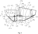
- a substantially U-shaped partition wall 54 is provided inside the fuel tank 22.
- This partition wall together with the outer wall portion 48, defines a removal tank volume 56 and separates it from what is generally referred to as the main tank volume. 58 designated remaining part of the tank volume 22.
- the withdrawal tank volume 56 can basically be divided into two by a dashed line S in Fig. 3 indicated areas. On the one hand, this is a lower withdrawal tank volume area 60 located below the dashed line S, which is delimited laterally by U-legs 62, 64 of the U-shaped partition 54 and is delimited downwards and in the forward and rearward directions by a wall section 66 of the outer wall part 48 adjoining the bottom wall 28 of the outer shell 26.
- an upper withdrawal tank volume area 68 which is delimited to the sides and rearward by the U-legs 62, 64 and a connecting section 70 of the partition 54, but is open to the front, or between the front end edges of the U-legs 62, 64 and an upwardly rising wall section 72 of the outer wall part 48, via lateral or wedge-shaped openings 74, 76 to the main tank volume 58.
- the upper withdrawal tank volume area 68 is also open to the main tank volume 58 in the upper edge area of the partition 54.
- the lower removal tank volume area 60 which has no direct fuel exchange connection with the main tank volume 58, but provides a closed tray downwards and laterally or forwardly, is substantially below the level provided by the bottom wall 28. This ensures that even with a minimum fill level of the fuel tank 20 and a substantially non-inclined positioning of the tank system 18, as shown in Fig. 3 As illustrated, fuel will always accumulate in the lower removal tank volume area 60. If the rear area of the tank system 18, i.e. in Fig. 3 If the right-hand area tilts downward, the partition wall 54 prevents the fuel present in the lower removal tank volume area 60 from leaking out. If the tank system 18 tilts downward at the front, all of the fuel present in the tank volume 22 will accumulate in the front area of the fuel tank 22 and thus also in the area of the lower removal tank volume area 60.
- the tank volume 22 is essentially divided by the two partition walls 38, 40 into a first Tank volume region 78 and a second tank volume region 80 essentially comprising the two lateral tank volume regions 30, 32.
- the first tank volume region 78 which essentially also provides the central tank volume region 42, is connected to the second tank volume region 80, which essentially provides the two lateral tank volume regions 30, 32, via recesses 82, 84, 86 formed in the intermediate walls 38, 40.
- a connecting wall 88 extending between the two intermediate walls 38, 40 is provided in the first tank volume region 78, which divides the central tank volume region 80 into regions communicating with one another due to the shape of the connecting wall 88.
- the connecting wall 88 essentially prevents excessive sloshing of the fuel present in the central tank volume region 42 in the machine longitudinal direction L.
- a fuel extraction arrangement is provided for conveying fuel present in the fuel tank 20 to a fuel-consuming system region 96, for example, a diesel internal combustion engine of the construction machine 11.
- This arrangement comprises an extraction line 94 leading from the lower extraction tank volume region 60 to a main fuel pump 92.
- the fuel is then conveyed by the main fuel pump 92 toward the fuel-consuming system region 96.
- the fuel not required therein is fed back into the extraction tank volume 56, in particular the lower extraction tank volume region 60, via a return line 98.
- the tank system 18 further comprises a fuel feed arrangement, generally designated 100.
- An essential component of the fuel feed arrangement 100 is an auxiliary fuel pump 102, which withdraws fuel from the main tank volume 58, in particular the first tank volume region 78 of the tank volume 22, via a first feed line 104 and feeds it into the withdrawal tank volume 56 in the region of the upper withdrawal tank volume region 68 via a fuel filter 106 connected upstream of the auxiliary fuel pump 102 and a second feed line 108.
- the auxiliary fuel pump 102 of the fuel supply arrangement 100 can preferably be operated permanently whenever the main fuel pump 92 of the fuel extraction arrangement 90 is also operated. In this way, it is ensured that, regardless of the inclination positioning of the construction machine 11 or the tank system 18, there is always sufficient fuel in the extraction tank volume 56, in particular in the lower extraction tank volume region 60 thereof, so that a condition in which the end region of the extraction line 94 engaging in the lower extraction tank volume region 60 is not immersed in fuel and thus the main fuel pump 92 would suck in air, cannot occur.
- the operation of the auxiliary fuel pump 102 further ensures that the fuel present in the tank volume 22 is constantly circulated, so that, on the one hand, the settling of contaminants is prevented, and on the other hand, contaminants carried along during circulation can be filtered out in the fuel filter 106. Furthermore, this circulation, which is established during the delivery operation of the main fuel pump 92, ensures that there is constant mixing of the generally heated fuel fed back via the return line 98 with the fuel present in the fuel tank 20, so that excessive heating, in particular of the fuel present in the withdrawal tank volume 56, can be avoided.
- a filler neck 112 is provided, which provides a filling opening open to the lateral tank volume area 32.
- This lateral positioning of the filler neck 112 prevents mutual interference with system areas arranged centrally on the machine frame 10, such as the diesel internal combustion engine, which can, for example, be arranged such that it is positioned in the rear area of the machine frame 10 above the two partition walls 38, 40, so that the partition walls 38, 40 can also fulfill a supporting function for the diesel internal combustion engine.
- the additional fuel pump 102 can be activated to ensure that there is sufficient fuel in the withdrawal tank volume 56.
- a tank system for a construction machine ensures that, regardless of the position of such a construction machine during operation, and thus also regardless of any inclination of the tank system relative to a horizontal plane, sufficient fuel is always available in the area from which it is pumped towards the fuel-consuming system area. Since, in this tank system, the tank volume is also limited in significant areas by an outer shell of a machine frame or construction machine, and thus no further cladding parts or frame parts are provided to enclose the outer wall of the tank system, efficient use of the installation space available on a construction machine for storing fuel is ensured.
Landscapes
- Engineering & Computer Science (AREA)
- Combustion & Propulsion (AREA)
- Mechanical Engineering (AREA)
- Chemical & Material Sciences (AREA)
- General Engineering & Computer Science (AREA)
- Transportation (AREA)
- Life Sciences & Earth Sciences (AREA)
- Sustainable Energy (AREA)
- Sustainable Development (AREA)
- Architecture (AREA)
- Civil Engineering (AREA)
- Structural Engineering (AREA)
- Cooling, Air Intake And Gas Exhaust, And Fuel Tank Arrangements In Propulsion Units (AREA)
Claims (15)
- Une machine de construction avec un système de réservoir, le système de réservoir comprenant :- un réservoir de carburant (20) ayant une paroi extérieure de réservoir (24) qui ferme un volume de réservoir (22) vers l'extérieur,- un volume de réservoir de prélèvement (56) séparé par une paroi de séparation (54) d'un volume de réservoir principal (58) du volume de réservoir (22) et en communication d'échange de carburant avec le volume de réservoir principal (58),- un dispositif de prélèvement de carburant (90) comprenant une pompe à carburant principale (92) et une conduite de prélèvement (94) débouchant dans le volume de réservoir de prélèvement (56) pour acheminer le carburant au moyen de la pompe à carburant principale (92) via la conduite de prélèvement (94) du volume de réservoir de prélèvement (56) vers une zone de système consommatrice de carburant (96),- un dispositif d'alimentation en carburant (100) comportant une pompe à carburant auxiliaire (102) pour acheminer le carburant du volume de réservoir principal (58) dans le volume de réservoir de prélèvement (56),dans lequel le volume de réservoir de prélèvement (56) comprend une zone inférieure de volume de réservoir de prélèvement (60) par rapport à une direction verticale (V) et une zone supérieure de volume de réservoir de prélèvement (68) adjacente à la zone inférieure de volume de réservoir de prélèvement (60) dans la direction verticale (V), dans lequel la zone inférieure de volume de réservoir de prélèvement (60) est séparée du volume de réservoir principal (58) de telle sorte qu'il n'y ait pas de connexion directe d'échange de carburant entre le volume de réservoir principal (58) et le volume de réservoir de prélèvement inférieur (60),caractérisé en ce que, dans le cas d'un positionnement du système de réservoir qui n'est pas incliné par rapport à un plan horizontal, la zone inférieure de volume de réservoir de prélèvement (66) est positionnée dans la direction verticale (V) essentiellement complètement sous une paroi inférieure (28) de la paroi extérieure de réservoir (24) dans la région du volume de réservoir principal (58).
- La machine de construction selon la revendication 1,
caractérisée en ce que la conduite de prélèvement (94) débouche dans le volume de réservoir de prélèvement (56) dans la région de la zone inférieure de volume de réservoir de prélèvement (60). - La machine de construction selon l'une des revendications précédentes,
caractérisée en ce que le dispositif d'alimentation en carburant (100) comprend une première conduite d'alimentation (104) débouchant dans le volume de réservoir principal (58) et menant du volume de réservoir principal (58) à la pompe à carburant auxiliaire (102) et une seconde conduite d'alimentation (108) débouchant dans le volume de réservoir de prélèvement (56) et menant de la pompe à carburant auxiliaire (102) au volume de réservoir de prélèvement (56). - La machine de construction selon la revendication 3,
caractérisée en ce que la seconde conduite d'alimentation (108) débouche dans le volume de réservoir de prélèvement (56) dans la région de la zone supérieure du volume de réservoir de prélèvement (68). - La machine de construction selon la revendication 3 ou 4,
caractérisée en ce qu'un filtre à carburant (106) est disposé dans la région de la première conduite d'alimentation (104). - La machine de construction selon l'une des revendications précédentes,
caractérisée en ce que le volume de réservoir (22) est divisé par au moins une paroi intermédiaire (38, 40) en une première zone de volume de réservoir (78) contenant le volume de réservoir de prélèvement (56) et une seconde zone de volume de réservoir (80) ayant une connexion d'échange de carburant avec le premier volume de réservoir (78). - La machine de construction selon la revendication 3 et la revendication 6,
caractérisée en ce que la première conduite d'alimentation (104) débouche dans le volume de réservoir principal (58) dans la région de la première zone de volume de réservoir (78). - La machine de construction selon l'une des revendications précédentes,
caractérisée en ce qu'une conduite de retour (98) débouchant dans le volume de réservoir (22) est prévue pour renvoyer le carburant acheminé par la pompe à carburant principale (92) du volume de réservoir de prélèvement (56) dans le volume de réservoir (22), dans lequel la conduite de retour (98) débouche dans le volume de réservoir (92) dans la région du volume de réservoir de prélèvement (56). - La machine de construction selon l'une des revendications précédentes,
caractérisée en ce que le dispositif d'alimentation en carburant (100) est conçu pour alimenter en carburant alternativement le volume de réservoir de prélèvement (56) ou la zone de système consommateur de carburant (96). - La machine de construction selon l'une des revendications précédentes,
caractérisée en ce que le dispositif d'alimentation en carburant (100) est conçu pour faire fonctionner en permanence la pompe à carburant auxiliaire (102) pendant le fonctionnement de la pompe à carburant principale (92). - La machine de construction selon l'une des revendications précédentes,
caractérisée en ce qu'une partie de la paroi extérieure du réservoir (24) constitue un boîtier extérieur (26) pour la machine de construction (10). - La machine de construction selon l'une des revendications précédentes,
caractérisée en ce que le volume de réservoir (22) comprend une zone de volume de réservoir (42) qui est essentiellement centrale par rapport à une direction transversale de la machine (Q) et des zones de volume de réservoir latérales (30, 32) des deux côtés de la zone de volume de réservoir centrale (42) par rapport à une direction longitudinale de la machine (L). - La machine de construction selon la revendication 12, si elle est renvoyée à la revendication 7,
caractérisée en ce que la zone de volume de réservoir centrale (42) est essentiellement constituée par la première zone de volume de réservoir (78), et en ce que les zones latérales de volume de réservoir (30, 32) sont essentiellement constituées par la seconde zone de volume de réservoir (80). - La machine de construction selon la revendication 12 ou 13,
caractérisée en ce qu'une ouverture de remplissage pour remplir de carburant le volume de réservoir (22) est ouverte sur l'une des zones latérales de volume de réservoir (30, 32). - Un procédé de fonctionnement du système de réservoir de la machine de construction selon l'une des revendications 1 à 14, dans lequel la pompe à carburant auxiliaire (102) pour acheminer le carburant du volume de réservoir principal (58) dans le volume de réservoir de prélèvement (56) est actionnée lorsque les informations de niveau de remplissage fournies par un système de capteurs indiquent que le niveau de remplissage dans le volume de réservoir de prélèvement (56) est trop bas.
Applications Claiming Priority (1)
| Application Number | Priority Date | Filing Date | Title |
|---|---|---|---|
| DE102019133272.9A DE102019133272A1 (de) | 2019-12-06 | 2019-12-06 | Tanksystem |
Publications (2)
| Publication Number | Publication Date |
|---|---|
| EP3832122A1 EP3832122A1 (fr) | 2021-06-09 |
| EP3832122B1 true EP3832122B1 (fr) | 2025-05-28 |
Family
ID=73059503
Family Applications (1)
| Application Number | Title | Priority Date | Filing Date |
|---|---|---|---|
| EP20205346.8A Active EP3832122B1 (fr) | 2019-12-06 | 2020-11-03 | Machine de chantier avec un système de réservoir |
Country Status (4)
| Country | Link |
|---|---|
| US (1) | US11541748B2 (fr) |
| EP (1) | EP3832122B1 (fr) |
| CN (2) | CN112922756B (fr) |
| DE (1) | DE102019133272A1 (fr) |
Families Citing this family (1)
| Publication number | Priority date | Publication date | Assignee | Title |
|---|---|---|---|---|
| DE102019133272A1 (de) * | 2019-12-06 | 2021-06-10 | Hamm Ag | Tanksystem |
Family Cites Families (11)
| Publication number | Priority date | Publication date | Assignee | Title |
|---|---|---|---|---|
| JP5198578B2 (ja) * | 2008-11-07 | 2013-05-15 | 本田技研工業株式会社 | 燃料タンク |
| DE102009049799B4 (de) * | 2009-10-16 | 2018-07-12 | Kautex Textron Gmbh & Co. Kg | Kraftstoffbehälter für ein KFZ |
| EP2628623B1 (fr) * | 2012-02-15 | 2016-11-30 | Magna Steyr Fuel Systems GesmbH | Dispositif de réservoir de carburant pour un véhicule utilitaire |
| SE537006C2 (sv) * | 2013-03-22 | 2014-12-02 | Scania Cv Ab | Bränslesystem för förbränningsmotor och ett förfarande för att byta filterelement i ett bränslesystem |
| DE102013011665A1 (de) * | 2013-07-11 | 2015-01-15 | Man Truck & Bus Ag | Kraftstofftank für ein Kraftfahrzeug und Auslieferungsverfahren für ein Kraftfahrzeug |
| DE202014010518U1 (de) * | 2014-12-18 | 2015-11-09 | Hamm Ag | Bodenbearbeitungsmaschine, insbesondere Bodenverdichter |
| DE102016009228B4 (de) * | 2016-07-28 | 2021-02-04 | Audi Ag | Kraftstofftank für ein Kraftfahrzeug und Kraftfahrzeug |
| DE102016014881A1 (de) * | 2016-12-14 | 2017-07-06 | Daimler Ag | Kraftstofftanksystem |
| EP3403864B1 (fr) * | 2017-05-18 | 2020-01-08 | Ningbo Geely Automobile Research & Development Co., Ltd. | Ensemble éjecteur de carburant pour un véhicule |
| JP6943721B2 (ja) * | 2017-10-12 | 2021-10-06 | トヨタ自動車株式会社 | 燃料タンク |
| DE102019133272A1 (de) * | 2019-12-06 | 2021-06-10 | Hamm Ag | Tanksystem |
-
2019
- 2019-12-06 DE DE102019133272.9A patent/DE102019133272A1/de active Pending
-
2020
- 2020-11-03 EP EP20205346.8A patent/EP3832122B1/fr active Active
- 2020-11-25 US US17/104,113 patent/US11541748B2/en active Active
- 2020-12-07 CN CN202011430872.3A patent/CN112922756B/zh active Active
- 2020-12-07 CN CN202022963592.0U patent/CN215672504U/zh not_active Withdrawn - After Issue
Also Published As
| Publication number | Publication date |
|---|---|
| EP3832122A1 (fr) | 2021-06-09 |
| US20210170864A1 (en) | 2021-06-10 |
| US11541748B2 (en) | 2023-01-03 |
| DE102019133272A1 (de) | 2021-06-10 |
| CN112922756A (zh) | 2021-06-08 |
| CN215672504U (zh) | 2022-01-28 |
| BR102020020837A2 (pt) | 2021-06-22 |
| CN112922756B (zh) | 2023-04-28 |
Similar Documents
| Publication | Publication Date | Title |
|---|---|---|
| DE102009001460B4 (de) | Ölbehälter | |
| DE10208788B4 (de) | Duale Brennstofflieferung-Modulsysteme für Mehrkammertanks oder mehrere automotive Brennstofftanks und Verfahren zum Liefern von Brennstoff | |
| EP2488382B1 (fr) | Réservoir de carburant pour véhicule automobile | |
| WO2002038409A1 (fr) | Reservoir de carburant | |
| DE102016109023B4 (de) | Kraftstofftankaufbau | |
| DE102008008466A1 (de) | Fluidverdrängungsbehälter | |
| DE102005002264A1 (de) | Strahlpumpe mit verbesserter Starteigenschaft | |
| DE102007048333A1 (de) | Flüssigkeitsspeicher | |
| DE2344949A1 (de) | Schmiervorrichtung fuer brennkraftmaschinen zur sicheren oelversorgung bei grossen schraeglagen | |
| EP3832122B1 (fr) | Machine de chantier avec un système de réservoir | |
| DE10238237A1 (de) | Kammerentleerungseinrichtung | |
| DE19805072C2 (de) | Kraftstoffördermodul | |
| EP2738032B1 (fr) | Système de réservoir pour un véhicule automobile | |
| WO2021190927A1 (fr) | Chambre de compensation d'huile pour boîte de vitesses | |
| EP2628623B1 (fr) | Dispositif de réservoir de carburant pour un véhicule utilitaire | |
| EP0608499B1 (fr) | Système de réservoir de carburant liquide, notamment pour moteur à combustion pour véhicules à moteur | |
| EP3572663B1 (fr) | Filtre à combustible destiné au nettoyage du combustible pour un moteur à combustion interne | |
| DE102004045441B4 (de) | Vorrichtung zur Versorgung eines Antriebs mit flüssigem Schmiermittel | |
| DE102006021678B4 (de) | Vorrichtung zur Versorgung eines Antriebs mit flüssigem Schmiermittel | |
| DE102014202361B4 (de) | Kraftstofftanksystem | |
| EP3382193B1 (fr) | Filtre à carburant permettant de filtrer le carburant dans un véhicule automobile et véhicule automobile pourvu d'un tel filtre à carburant | |
| DE102015203053B4 (de) | Verwendung einer Zusatzleitung eines Kraftstofftanks zur Versorgung von zumindest einem Zusatzaggregat | |
| DE2852416A1 (de) | Fluessigkeitssystem mit zusatztank und mehreren ausgleichsleitungen | |
| DE102021126390B4 (de) | Schmierstruktur einer kraftübertragungsvorrichtung | |
| DE102019108893A1 (de) | Tankanlage für ein Kraftfahrzeug |
Legal Events
| Date | Code | Title | Description |
|---|---|---|---|
| PUAI | Public reference made under article 153(3) epc to a published international application that has entered the european phase |
Free format text: ORIGINAL CODE: 0009012 |
|
| STAA | Information on the status of an ep patent application or granted ep patent |
Free format text: STATUS: REQUEST FOR EXAMINATION WAS MADE |
|
| 17P | Request for examination filed |
Effective date: 20201103 |
|
| AK | Designated contracting states |
Kind code of ref document: A1 Designated state(s): AL AT BE BG CH CY CZ DE DK EE ES FI FR GB GR HR HU IE IS IT LI LT LU LV MC MK MT NL NO PL PT RO RS SE SI SK SM TR |
|
| STAA | Information on the status of an ep patent application or granted ep patent |
Free format text: STATUS: EXAMINATION IS IN PROGRESS |
|
| 17Q | First examination report despatched |
Effective date: 20231102 |
|
| GRAP | Despatch of communication of intention to grant a patent |
Free format text: ORIGINAL CODE: EPIDOSNIGR1 |
|
| STAA | Information on the status of an ep patent application or granted ep patent |
Free format text: STATUS: GRANT OF PATENT IS INTENDED |
|
| RIC1 | Information provided on ipc code assigned before grant |
Ipc: F02M 37/02 20060101ALN20250228BHEP Ipc: E01C 19/22 20060101ALI20250228BHEP Ipc: B60K 15/077 20060101ALI20250228BHEP Ipc: B60K 15/03 20060101ALI20250228BHEP Ipc: F02M 37/18 20060101ALI20250228BHEP Ipc: F02M 37/10 20060101ALI20250228BHEP Ipc: E01C 19/00 20060101ALI20250228BHEP Ipc: B60K 15/073 20060101ALI20250228BHEP Ipc: B60K 15/063 20060101ALI20250228BHEP Ipc: F02M 37/00 20060101AFI20250228BHEP |
|
| GRAS | Grant fee paid |
Free format text: ORIGINAL CODE: EPIDOSNIGR3 |
|
| INTG | Intention to grant announced |
Effective date: 20250324 |
|
| GRAA | (expected) grant |
Free format text: ORIGINAL CODE: 0009210 |
|
| STAA | Information on the status of an ep patent application or granted ep patent |
Free format text: STATUS: THE PATENT HAS BEEN GRANTED |
|
| P01 | Opt-out of the competence of the unified patent court (upc) registered |
Free format text: CASE NUMBER: APP_16654/2025 Effective date: 20250407 |
|
| AK | Designated contracting states |
Kind code of ref document: B1 Designated state(s): AL AT BE BG CH CY CZ DE DK EE ES FI FR GB GR HR HU IE IS IT LI LT LU LV MC MK MT NL NO PL PT RO RS SE SI SK SM TR |
|
| REG | Reference to a national code |
Ref country code: GB Ref legal event code: FG4D Free format text: NOT ENGLISH |
|
| REG | Reference to a national code |
Ref country code: CH Ref legal event code: EP |
|
| REG | Reference to a national code |
Ref country code: DE Ref legal event code: R096 Ref document number: 502020011125 Country of ref document: DE |
|
| REG | Reference to a national code |
Ref country code: IE Ref legal event code: FG4D Free format text: LANGUAGE OF EP DOCUMENT: GERMAN |
|
| REG | Reference to a national code |
Ref country code: SE Ref legal event code: TRGR |
|
| REG | Reference to a national code |
Ref country code: NL Ref legal event code: MP Effective date: 20250528 |
|
| PG25 | Lapsed in a contracting state [announced via postgrant information from national office to epo] |
Ref country code: FI Free format text: LAPSE BECAUSE OF FAILURE TO SUBMIT A TRANSLATION OF THE DESCRIPTION OR TO PAY THE FEE WITHIN THE PRESCRIBED TIME-LIMIT Effective date: 20250528 Ref country code: ES Free format text: LAPSE BECAUSE OF FAILURE TO SUBMIT A TRANSLATION OF THE DESCRIPTION OR TO PAY THE FEE WITHIN THE PRESCRIBED TIME-LIMIT Effective date: 20250528 |
|
| REG | Reference to a national code |
Ref country code: LT Ref legal event code: MG9D |
|
| PG25 | Lapsed in a contracting state [announced via postgrant information from national office to epo] |
Ref country code: NO Free format text: LAPSE BECAUSE OF FAILURE TO SUBMIT A TRANSLATION OF THE DESCRIPTION OR TO PAY THE FEE WITHIN THE PRESCRIBED TIME-LIMIT Effective date: 20250828 Ref country code: GR Free format text: LAPSE BECAUSE OF FAILURE TO SUBMIT A TRANSLATION OF THE DESCRIPTION OR TO PAY THE FEE WITHIN THE PRESCRIBED TIME-LIMIT Effective date: 20250829 |
|
| PG25 | Lapsed in a contracting state [announced via postgrant information from national office to epo] |
Ref country code: PL Free format text: LAPSE BECAUSE OF FAILURE TO SUBMIT A TRANSLATION OF THE DESCRIPTION OR TO PAY THE FEE WITHIN THE PRESCRIBED TIME-LIMIT Effective date: 20250528 Ref country code: NL Free format text: LAPSE BECAUSE OF FAILURE TO SUBMIT A TRANSLATION OF THE DESCRIPTION OR TO PAY THE FEE WITHIN THE PRESCRIBED TIME-LIMIT Effective date: 20250528 |
|
| PG25 | Lapsed in a contracting state [announced via postgrant information from national office to epo] |
Ref country code: BG Free format text: LAPSE BECAUSE OF FAILURE TO SUBMIT A TRANSLATION OF THE DESCRIPTION OR TO PAY THE FEE WITHIN THE PRESCRIBED TIME-LIMIT Effective date: 20250528 |
|
| PG25 | Lapsed in a contracting state [announced via postgrant information from national office to epo] |
Ref country code: HR Free format text: LAPSE BECAUSE OF FAILURE TO SUBMIT A TRANSLATION OF THE DESCRIPTION OR TO PAY THE FEE WITHIN THE PRESCRIBED TIME-LIMIT Effective date: 20250528 |
|
| PG25 | Lapsed in a contracting state [announced via postgrant information from national office to epo] |
Ref country code: RS Free format text: LAPSE BECAUSE OF FAILURE TO SUBMIT A TRANSLATION OF THE DESCRIPTION OR TO PAY THE FEE WITHIN THE PRESCRIBED TIME-LIMIT Effective date: 20250828 |
|
| PG25 | Lapsed in a contracting state [announced via postgrant information from national office to epo] |
Ref country code: IS Free format text: LAPSE BECAUSE OF FAILURE TO SUBMIT A TRANSLATION OF THE DESCRIPTION OR TO PAY THE FEE WITHIN THE PRESCRIBED TIME-LIMIT Effective date: 20250928 |
|
| PG25 | Lapsed in a contracting state [announced via postgrant information from national office to epo] |
Ref country code: LV Free format text: LAPSE BECAUSE OF FAILURE TO SUBMIT A TRANSLATION OF THE DESCRIPTION OR TO PAY THE FEE WITHIN THE PRESCRIBED TIME-LIMIT Effective date: 20250528 |
|
| PGFP | Annual fee paid to national office [announced via postgrant information from national office to epo] |
Ref country code: DE Payment date: 20251119 Year of fee payment: 6 |
|
| PG25 | Lapsed in a contracting state [announced via postgrant information from national office to epo] |
Ref country code: DK Free format text: LAPSE BECAUSE OF FAILURE TO SUBMIT A TRANSLATION OF THE DESCRIPTION OR TO PAY THE FEE WITHIN THE PRESCRIBED TIME-LIMIT Effective date: 20250528 Ref country code: SM Free format text: LAPSE BECAUSE OF FAILURE TO SUBMIT A TRANSLATION OF THE DESCRIPTION OR TO PAY THE FEE WITHIN THE PRESCRIBED TIME-LIMIT Effective date: 20250528 |
|
| PGFP | Annual fee paid to national office [announced via postgrant information from national office to epo] |
Ref country code: SE Payment date: 20251119 Year of fee payment: 6 |
|
| PGFP | Annual fee paid to national office [announced via postgrant information from national office to epo] |
Ref country code: CZ Payment date: 20251029 Year of fee payment: 6 |
|
| PG25 | Lapsed in a contracting state [announced via postgrant information from national office to epo] |
Ref country code: EE Free format text: LAPSE BECAUSE OF FAILURE TO SUBMIT A TRANSLATION OF THE DESCRIPTION OR TO PAY THE FEE WITHIN THE PRESCRIBED TIME-LIMIT Effective date: 20250528 |
|
| PG25 | Lapsed in a contracting state [announced via postgrant information from national office to epo] |
Ref country code: SK Free format text: LAPSE BECAUSE OF FAILURE TO SUBMIT A TRANSLATION OF THE DESCRIPTION OR TO PAY THE FEE WITHIN THE PRESCRIBED TIME-LIMIT Effective date: 20250528 |
|
| PG25 | Lapsed in a contracting state [announced via postgrant information from national office to epo] |
Ref country code: IT Free format text: LAPSE BECAUSE OF FAILURE TO SUBMIT A TRANSLATION OF THE DESCRIPTION OR TO PAY THE FEE WITHIN THE PRESCRIBED TIME-LIMIT Effective date: 20250528 |
|
| REG | Reference to a national code |
Ref country code: DE Ref legal event code: R097 Ref document number: 502020011125 Country of ref document: DE |
|
| PG25 | Lapsed in a contracting state [announced via postgrant information from national office to epo] |
Ref country code: RO Free format text: LAPSE BECAUSE OF FAILURE TO SUBMIT A TRANSLATION OF THE DESCRIPTION OR TO PAY THE FEE WITHIN THE PRESCRIBED TIME-LIMIT Effective date: 20250528 |
|
| PLBE | No opposition filed within time limit |
Free format text: ORIGINAL CODE: 0009261 |
|
| STAA | Information on the status of an ep patent application or granted ep patent |
Free format text: STATUS: NO OPPOSITION FILED WITHIN TIME LIMIT |
|
| REG | Reference to a national code |
Ref country code: CH Ref legal event code: L10 Free format text: ST27 STATUS EVENT CODE: U-0-0-L10-L00 (AS PROVIDED BY THE NATIONAL OFFICE) Effective date: 20260409 |