EP3832172A1 - Kompakte drehmomentübertragungsvorrichtung für ein kraftfahrzeug - Google Patents
Kompakte drehmomentübertragungsvorrichtung für ein kraftfahrzeug Download PDFInfo
- Publication number
- EP3832172A1 EP3832172A1 EP20209429.8A EP20209429A EP3832172A1 EP 3832172 A1 EP3832172 A1 EP 3832172A1 EP 20209429 A EP20209429 A EP 20209429A EP 3832172 A1 EP3832172 A1 EP 3832172A1
- Authority
- EP
- European Patent Office
- Prior art keywords
- clutch
- player
- wheel
- transmission device
- revolution
- Prior art date
- Legal status (The legal status is an assumption and is not a legal conclusion. Google has not performed a legal analysis and makes no representation as to the accuracy of the status listed.)
- Granted
Links
Images


Classifications
-
- B—PERFORMING OPERATIONS; TRANSPORTING
- B60—VEHICLES IN GENERAL
- B60K—ARRANGEMENT OR MOUNTING OF PROPULSION UNITS OR OF TRANSMISSIONS IN VEHICLES; ARRANGEMENT OR MOUNTING OF PLURAL DIVERSE PRIME-MOVERS IN VEHICLES; AUXILIARY DRIVES FOR VEHICLES; INSTRUMENTATION OR DASHBOARDS FOR VEHICLES; ARRANGEMENTS IN CONNECTION WITH COOLING, AIR INTAKE, GAS EXHAUST OR FUEL SUPPLY OF PROPULSION UNITS IN VEHICLES
- B60K17/00—Arrangement or mounting of transmissions in vehicles
- B60K17/04—Arrangement or mounting of transmissions in vehicles characterised by arrangement, location or kind of gearing
- B60K17/043—Transmission unit disposed in on near the vehicle wheel, or between the differential gear unit and the wheel
-
- F—MECHANICAL ENGINEERING; LIGHTING; HEATING; WEAPONS; BLASTING
- F16—ENGINEERING ELEMENTS AND UNITS; GENERAL MEASURES FOR PRODUCING AND MAINTAINING EFFECTIVE FUNCTIONING OF MACHINES OR INSTALLATIONS; THERMAL INSULATION IN GENERAL
- F16H—GEARING
- F16H63/00—Control outputs from the control unit to change-speed- or reversing-gearings for conveying rotary motion or to other devices than the final output mechanism
- F16H63/02—Final output mechanisms therefor; Actuating means for the final output mechanisms
- F16H63/30—Constructional features of the final output mechanisms
-
- F—MECHANICAL ENGINEERING; LIGHTING; HEATING; WEAPONS; BLASTING
- F16—ENGINEERING ELEMENTS AND UNITS; GENERAL MEASURES FOR PRODUCING AND MAINTAINING EFFECTIVE FUNCTIONING OF MACHINES OR INSTALLATIONS; THERMAL INSULATION IN GENERAL
- F16H—GEARING
- F16H3/00—Toothed gearings for conveying rotary motion with variable gear ratio or for reversing rotary motion
- F16H3/02—Toothed gearings for conveying rotary motion with variable gear ratio or for reversing rotary motion without gears having orbital motion
- F16H3/20—Toothed gearings for conveying rotary motion with variable gear ratio or for reversing rotary motion without gears having orbital motion exclusively or essentially using gears that can be moved out of gear
-
- B—PERFORMING OPERATIONS; TRANSPORTING
- B60—VEHICLES IN GENERAL
- B60K—ARRANGEMENT OR MOUNTING OF PROPULSION UNITS OR OF TRANSMISSIONS IN VEHICLES; ARRANGEMENT OR MOUNTING OF PLURAL DIVERSE PRIME-MOVERS IN VEHICLES; AUXILIARY DRIVES FOR VEHICLES; INSTRUMENTATION OR DASHBOARDS FOR VEHICLES; ARRANGEMENTS IN CONNECTION WITH COOLING, AIR INTAKE, GAS EXHAUST OR FUEL SUPPLY OF PROPULSION UNITS IN VEHICLES
- B60K17/00—Arrangement or mounting of transmissions in vehicles
- B60K17/22—Arrangement or mounting of transmissions in vehicles characterised by arrangement, location, or type of main drive shafting, e.g. cardan shaft
-
- F—MECHANICAL ENGINEERING; LIGHTING; HEATING; WEAPONS; BLASTING
- F15—FLUID-PRESSURE ACTUATORS; HYDRAULICS OR PNEUMATICS IN GENERAL
- F15B—SYSTEMS ACTING BY MEANS OF FLUIDS IN GENERAL; FLUID-PRESSURE ACTUATORS, e.g. SERVOMOTORS; DETAILS OF FLUID-PRESSURE SYSTEMS, NOT OTHERWISE PROVIDED FOR
- F15B15/00—Fluid-actuated devices for displacing a member from one position to another; Gearing associated therewith
- F15B15/08—Characterised by the construction of the motor unit
- F15B15/14—Characterised by the construction of the motor unit of the straight-cylinder type
- F15B15/1423—Component parts; Constructional details
- F15B15/1447—Pistons; Piston to piston rod assemblies
-
- F—MECHANICAL ENGINEERING; LIGHTING; HEATING; WEAPONS; BLASTING
- F16—ENGINEERING ELEMENTS AND UNITS; GENERAL MEASURES FOR PRODUCING AND MAINTAINING EFFECTIVE FUNCTIONING OF MACHINES OR INSTALLATIONS; THERMAL INSULATION IN GENERAL
- F16D—COUPLINGS FOR TRANSMITTING ROTATION; CLUTCHES; BRAKES
- F16D21/00—Systems comprising a plurality of actuated clutches
- F16D21/02—Systems comprising a plurality of actuated clutches for interconnecting three or more shafts or other transmission members in different ways
- F16D21/04—Systems comprising a plurality of actuated clutches for interconnecting three or more shafts or other transmission members in different ways with a shaft carrying a number of rotatable transmission members, e.g. gears, each of which can be connected to the shaft by a clutching member or members between the shaft and the hub of the transmission member
-
- F—MECHANICAL ENGINEERING; LIGHTING; HEATING; WEAPONS; BLASTING
- F16—ENGINEERING ELEMENTS AND UNITS; GENERAL MEASURES FOR PRODUCING AND MAINTAINING EFFECTIVE FUNCTIONING OF MACHINES OR INSTALLATIONS; THERMAL INSULATION IN GENERAL
- F16D—COUPLINGS FOR TRANSMITTING ROTATION; CLUTCHES; BRAKES
- F16D23/00—Details of mechanically-actuated clutches not specific for one distinct type
- F16D23/02—Arrangements for synchronisation, also for power-operated clutches
-
- F—MECHANICAL ENGINEERING; LIGHTING; HEATING; WEAPONS; BLASTING
- F16—ENGINEERING ELEMENTS AND UNITS; GENERAL MEASURES FOR PRODUCING AND MAINTAINING EFFECTIVE FUNCTIONING OF MACHINES OR INSTALLATIONS; THERMAL INSULATION IN GENERAL
- F16H—GEARING
- F16H57/00—General details of gearing
- F16H57/02—Gearboxes; Mounting gearing therein
- F16H57/021—Shaft support structures, e.g. partition walls, bearing eyes, casing walls or covers with bearings
-
- F—MECHANICAL ENGINEERING; LIGHTING; HEATING; WEAPONS; BLASTING
- F16—ENGINEERING ELEMENTS AND UNITS; GENERAL MEASURES FOR PRODUCING AND MAINTAINING EFFECTIVE FUNCTIONING OF MACHINES OR INSTALLATIONS; THERMAL INSULATION IN GENERAL
- F16H—GEARING
- F16H57/00—General details of gearing
- F16H57/02—Gearboxes; Mounting gearing therein
- F16H57/023—Mounting or installation of gears or shafts in the gearboxes, e.g. methods or means for assembly
-
- F—MECHANICAL ENGINEERING; LIGHTING; HEATING; WEAPONS; BLASTING
- F16—ENGINEERING ELEMENTS AND UNITS; GENERAL MEASURES FOR PRODUCING AND MAINTAINING EFFECTIVE FUNCTIONING OF MACHINES OR INSTALLATIONS; THERMAL INSULATION IN GENERAL
- F16H—GEARING
- F16H61/00—Control functions within control units of change-speed- or reversing-gearings for conveying rotary motion ; Control of exclusively fluid gearing, friction gearing, gearings with endless flexible members or other particular types of gearing
- F16H61/04—Smoothing ratio shift
-
- F—MECHANICAL ENGINEERING; LIGHTING; HEATING; WEAPONS; BLASTING
- F16—ENGINEERING ELEMENTS AND UNITS; GENERAL MEASURES FOR PRODUCING AND MAINTAINING EFFECTIVE FUNCTIONING OF MACHINES OR INSTALLATIONS; THERMAL INSULATION IN GENERAL
- F16H—GEARING
- F16H63/00—Control outputs from the control unit to change-speed- or reversing-gearings for conveying rotary motion or to other devices than the final output mechanism
- F16H63/02—Final output mechanisms therefor; Actuating means for the final output mechanisms
- F16H63/30—Constructional features of the final output mechanisms
- F16H63/3023—Constructional features of the final output mechanisms the final output mechanisms comprising elements moved by fluid pressure
-
- B—PERFORMING OPERATIONS; TRANSPORTING
- B60—VEHICLES IN GENERAL
- B60Y—INDEXING SCHEME RELATING TO ASPECTS CROSS-CUTTING VEHICLE TECHNOLOGY
- B60Y2200/00—Type of vehicle
- B60Y2200/90—Vehicles comprising electric prime movers
- B60Y2200/91—Electric vehicles
-
- B—PERFORMING OPERATIONS; TRANSPORTING
- B60—VEHICLES IN GENERAL
- B60Y—INDEXING SCHEME RELATING TO ASPECTS CROSS-CUTTING VEHICLE TECHNOLOGY
- B60Y2200/00—Type of vehicle
- B60Y2200/90—Vehicles comprising electric prime movers
- B60Y2200/92—Hybrid vehicles
-
- F—MECHANICAL ENGINEERING; LIGHTING; HEATING; WEAPONS; BLASTING
- F16—ENGINEERING ELEMENTS AND UNITS; GENERAL MEASURES FOR PRODUCING AND MAINTAINING EFFECTIVE FUNCTIONING OF MACHINES OR INSTALLATIONS; THERMAL INSULATION IN GENERAL
- F16D—COUPLINGS FOR TRANSMITTING ROTATION; CLUTCHES; BRAKES
- F16D23/00—Details of mechanically-actuated clutches not specific for one distinct type
- F16D23/02—Arrangements for synchronisation, also for power-operated clutches
- F16D23/04—Arrangements for synchronisation, also for power-operated clutches with an additional friction clutch
- F16D23/06—Arrangements for synchronisation, also for power-operated clutches with an additional friction clutch and a blocking mechanism preventing the engagement of the main clutch prior to synchronisation
-
- F—MECHANICAL ENGINEERING; LIGHTING; HEATING; WEAPONS; BLASTING
- F16—ENGINEERING ELEMENTS AND UNITS; GENERAL MEASURES FOR PRODUCING AND MAINTAINING EFFECTIVE FUNCTIONING OF MACHINES OR INSTALLATIONS; THERMAL INSULATION IN GENERAL
- F16H—GEARING
- F16H63/00—Control outputs from the control unit to change-speed- or reversing-gearings for conveying rotary motion or to other devices than the final output mechanism
- F16H63/02—Final output mechanisms therefor; Actuating means for the final output mechanisms
- F16H63/30—Constructional features of the final output mechanisms
- F16H2063/3093—Final output elements, i.e. the final elements to establish gear ratio, e.g. coupling sleeves or other means establishing coupling to shaft
-
- Y—GENERAL TAGGING OF NEW TECHNOLOGICAL DEVELOPMENTS; GENERAL TAGGING OF CROSS-SECTIONAL TECHNOLOGIES SPANNING OVER SEVERAL SECTIONS OF THE IPC; TECHNICAL SUBJECTS COVERED BY FORMER USPC CROSS-REFERENCE ART COLLECTIONS [XRACs] AND DIGESTS
- Y02—TECHNOLOGIES OR APPLICATIONS FOR MITIGATION OR ADAPTATION AGAINST CLIMATE CHANGE
- Y02T—CLIMATE CHANGE MITIGATION TECHNOLOGIES RELATED TO TRANSPORTATION
- Y02T10/00—Road transport of goods or passengers
- Y02T10/60—Other road transportation technologies with climate change mitigation effect
- Y02T10/62—Hybrid vehicles
-
- Y—GENERAL TAGGING OF NEW TECHNOLOGICAL DEVELOPMENTS; GENERAL TAGGING OF CROSS-SECTIONAL TECHNOLOGIES SPANNING OVER SEVERAL SECTIONS OF THE IPC; TECHNICAL SUBJECTS COVERED BY FORMER USPC CROSS-REFERENCE ART COLLECTIONS [XRACs] AND DIGESTS
- Y04—INFORMATION OR COMMUNICATION TECHNOLOGIES HAVING AN IMPACT ON OTHER TECHNOLOGY AREAS
- Y04S—SYSTEMS INTEGRATING TECHNOLOGIES RELATED TO POWER NETWORK OPERATION, COMMUNICATION OR INFORMATION TECHNOLOGIES FOR IMPROVING THE ELECTRICAL POWER GENERATION, TRANSMISSION, DISTRIBUTION, MANAGEMENT OR USAGE, i.e. SMART GRIDS
- Y04S10/00—Systems supporting electrical power generation, transmission or distribution
- Y04S10/12—Monitoring or controlling equipment for energy generation units, e.g. distributed energy generation [DER] or load-side generation
- Y04S10/126—Monitoring or controlling equipment for energy generation units, e.g. distributed energy generation [DER] or load-side generation the energy generation units being or involving electric vehicles [EV] or hybrid vehicles [HEV], i.e. power aggregation of EV or HEV, vehicle to grid arrangements [V2G]
Definitions
- the invention relates to a torque transmission device for an electric or hybrid vehicle, in particular for an electric or hybrid motor vehicle.
- the invention applies more particularly to hybrid vehicles and to electric vehicles.
- the speeds of an electric motor can be high, greater than or equal to 15,000 revolutions per minute, for example, in particular for two-speed electric transmission chains.
- a transmission comprising a speed reduction device to achieve the desired output speed and torque levels at each wheel, and a differential to vary the speed. speed between two laterally opposed wheels.
- This device is not satisfactory from the point of view of efficiency because a pair of drag occurs on one of the clutches which is open when the other of the clutches is closed. This drag torque is particularly detrimental when the clutches are wet.
- the clutches of this device transmit a relatively large torque, which implies a sizing and a large mass of the clutches, and therefore a large size associated with the clutches.
- clutches in particular progressive multi-disc clutches, also makes it possible to guarantee user comfort by avoiding abrupt gear changes as well as perceptible variations in acceleration.
- connection element makes it possible to interrupt the drive of the output element of the first clutch, and in particular the output friction discs of the first clutch, when the second clutch is closed, which makes it possible to improve fuel efficiency by significantly limiting or even eliminating the drag torque at the first clutch when the second clutch is closed.
- connection element incorporates an actuator, the movable member of which is generally fixed in rotation, and a rotary kinematic connection between this movable member and a rotating part which performs or interrupts the mutual drive in rotation of the first output member of the first. clutch and transmission member.
- the movable member may for example be a clutch fork and the rotary kinematic linkage a rotating bearing stop. But such an arrangement is bulky and relatively complex.
- the invention aims to simplify and make more compact the connection element.
- first clutch interface and the second clutch interface consist of annular grooves of identical pitch, in which teeth of the intermediate clutch interface slide axially.
- a single tooth or spline is sufficient on the intermediate coasting interface, which can slide in a single spline or on a single tooth of the first interconnection interface and of the second interconnection interface.
- the elastic member gives the clutch produced by the three clutch interfaces a “normally open” coupling function.
- the torque transmission device thus has great axial compactness.
- the second clutch interface is positioned in the housing of the idle transmission wheel, the first clutch interface preferably being housed at least partially in the housing of the idle transmission wheel.
- the player is at least partially housed in the housing of the idle transmission wheel.
- the elastic return member is fixed in rotation about the axis of revolution.
- the torque transmission device further comprises a fixed support, one end of the elastic return member bearing against a support integral with the fixed support.
- the elastic return member is not part of the rotating assembly which must be accelerated at each coupling, which limits the transient torque of the coupling system during the coupling phases.
- the elastic return member may be formed by one or more springs, in particular by helical springs whose axes are parallel to the axis of revolution and distant from the axis of revolution, evenly distributed around the axis of revolution.
- a guide bearing is mounted, for example shrink-wrapped, on the transmission shaft and in a housing of the fixed support.
- the actuator can be electromechanical if necessary.
- the movable member comprises an annular piston capable of sliding axially in an annular chamber with variable volume of the fixed support, connected to a hydraulic supply connection.
- the hydraulic drive ensures high compactness at a very low cost.
- the hydraulic cylinder produced by the piston sliding in the annular chamber is monodirectional, the return to the rest position being provided by the elastic return member.
- the movable member in the activated position is at least partially engaged in the housing of the idle transmission wheel.
- the rotary kinematic connection comprises an intermediate pusher between the movable member and the elastic return member, the pusher being fixed in rotation around the axis of revolution, resting against the movable member and against the elastic return member, and linked to the player by a guide in rotation around the axis of revolution, the guide in rotation being preferably housed in the housing of the idle transmission wheel.
- the rotational guide comprises at least one annular pad, the annular pad being positioned at least partially between two opposite walls of the player and at least partially between two opposite walls of the pusher.
- the two opposite walls of the player can be formed on an annular radial rib of the player, which penetrates into an annular groove of the shoe.
- the opposite walls of the player can be formed by opposite sides of an annular groove formed in the player, and in which the shoe is at least partially engaged.
- the annular pad is positioned at least partially between two opposite walls of the pusher, preferably annular.
- the two opposite walls of the pusher are formed on an annular radial rib of the pusher, which penetrates into an annular groove of the pad.
- the opposite walls of the pusher can be formed by opposite sides of an annular groove formed in the pusher, and in which the pad is at least partially engaged.
- the shoe is housed in the housing of the idle transmission wheel.
- the structure of the rotary kinematic link makes it possible to very simply perform the function of transmitting the translational movements without transmitting the rotational movements around the axis of revolution. Its positioning contributes to the compactness of the torque transmission device.
- the torque transmission device comprises, interposed axially between the first clutch interface and the second clutch interface, a synchronizer comprising at least one synchronization ring, the player in the retracted position not causing the synchronization ring, the sliding gear being able, by passing during an axial translation from the retracted position to the coupling position, to pass through an intermediate synchronization position in which the intermediate clutch interface is engaged in a synchronization clutch interface of the synchronization ring and performs a rotational coupling between the first clutch interface and the synchronization ring, the synchronization ring being able to rotate relative to the second clutch interface around the axis of revolution by generating by friction a driving torque of the second clutch interface.
- the synchronizer allows a gradual setting in motion of the second clutch interface in the transient coupling phase, which avoids excessive torque peaks and shocks between the intermediate clutch interface and the other of the first and second clutch interfaces.
- the synchronizer is housed in the housing of the idle transmission wheel.
- the player is at least partially housed in the housing of the idle transmission wheel.
- the terms “external” and “internal” will be used as well as the “axial” and “radial” orientations to denote, according to the definitions given in the description, elements of the transmission device.
- the "radial” orientation is directed orthogonally to the axial orientation.
- the axial orientation relates, depending on the context, to the axis of rotation of one of the shafts, for example the output shaft of the motor or the transmission shaft 5.
- the "circumferential" orientation is directed orthogonally. to the axial direction and orthogonally to the radial direction.
- the various members of the transmission device each have a torque input, also called an input element, as well as a torque output, also called an output element.
- the inlet is kinematically located on the engine side and the outlet is located on the wheel side of the vehicle.
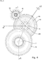
- a torque transmission system comprising an electric motor 4 of a motor vehicle capable of moving the vehicle forward, and a torque transmission assembly.
- the torque transmission assembly comprises a transmission device 10 and a differential 7 capable of driving two laterally opposed wheels, or two motorized front and rear wheel sets of the vehicle.
- the torque transmission device 10 comprises an output member 9 coupled to the differential 7.
- speed ratio is understood to mean the ratio between the speed at the output of the transmission mechanism and the speed at the input of the transmission mechanism.
- the first input element of the first clutch 1 and the second element input of the second clutch 2 are arranged to be driven by a common torque input shaft 8 which is here the output shaft of the engine 4.
- the clutches 1 and 2 are placed kinematically as close as possible to the engine 4, in upstream of the reduction devices, which means that the two clutches are placed in a portion of the transmission chain where the torque is the lowest.
- this arrangement allows better compactness of the clutches.
- the first clutch 1 is a progressive friction clutch and the second clutch 2 is a progressive friction clutch. So gear changes can be smooth and gradual without abrupt acceleration.
- the term “progressive clutch” is understood to mean a clutch, the transmissible torque of which can be controlled progressively. Where appropriate, the first clutch 1 and the second clutch 2 can jointly form a double clutch.
- a speed reducer 14 is here formed by the output member 9 and the differential 7 by means of a pinion forming the control member. output 9 meshing with a toothed wheel 70 arranged at the input of the differential 7.
- the coupling system 6 is arranged to allow the mutual drive in rotation between the first output element of the first clutch 1 and the transmission shaft 5, by means of the first transmission mechanism 11, when the first clutch 1 is closed, and to interrupt the mutual rotational drive between the first output member of the first clutch 1 and the transmission shaft 5, through the first transmission mechanism 11, when the first clutch is open and the second clutch closed.
- the coupling system is arranged so as to allow or interrupt the mutual drive directly between the transmission shaft 5 and the first transmission mechanism 11.
- the first transmission mechanism 11 is a speed reduction gear train.
- the second transmission mechanism 12 is also a speed reduction gear train. These gear trains can be mounted so as to bubble in the oil.
- the first transmission mechanism 11 has a lower speed ratio than the second transmission mechanism 12.
- the first transmission mechanism is used to propel the vehicle at relatively low speeds, and the second transmission mechanism is used to propel the vehicle. at relatively high speeds.
- the first transmission mechanism 11 comprises a first input shaft 41 integral in rotation with a first input toothed wheel 42 or pinion 42, an output toothed wheel 43 here directly meshing with the first input toothed wheel 42.
- the second transmission mechanism 12 comprises a second input shaft 51 integral in rotation with a second input toothed wheel 52 or pinion 52, a second output toothed wheel 53 here meshing directly with the second input toothed wheel 52 .
- the second input shaft is a hollow shaft 51 and the first input shaft 41 extends inside this hollow shaft 51.
- the second input shaft 51 and the first input shaft 41 are coaxial.
- the pinion 42 can be mounted or formed integrally with the first input shaft 41.
- the pinion 52 may be mounted or formed integrally with the second input shaft 51.
- the second output toothed wheel 53 is integral in rotation with the transmission shaft 5, for example via splines.
- the first output toothed wheel 43 is an idler wheel which rotates around the axis of revolution 100 of the transmission shaft 5, but can be made integral in rotation with the transmission shaft 5 by means of the system d. 'coupling 6.
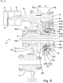
- a needle bearing 430 ensures the rotational guidance of the first output toothed wheel 43 on a cylindrical surface of the transmission shaft 5.
- the coupling system 6, illustrated in detail on the figures 3 and 7 comprises a first clutch interface 61 constituted here by a first spline formed at the periphery of a wheel 610 shrunk or secured by splines on the transmission shaft 5, a second clutch interface 62 constituted by a second spline formed by the periphery of a ring 620 shrunk onto the first output toothed wheel 43 and a sliding gear 63 comprising an intermediate clutch interface 64 formed by an intermediate spline arranged to cooperate with the first spline 61 and the second spline 62.
- the grooves 61, 62, 64 are composed of grooves separated by ribs or teeth, which extend axially parallel to the axis of revolution 100.
- the teeth of the intermediate groove 64 are here turned radially towards the axis. 'inside to penetrate into the corresponding grooves of the first groove 61 and of the second groove 62.
- the intermediate groove 64 is permanently engaged with the first groove 61.
- the slide 63 which carries the intermediate groove 64 is able to pass, through translation parallel to the axis of revolution 100, from a retracted position illustrated on the figures 1 to 3 , wherein the intermediate spline 64 is not engaged with the second spline 62, at a mating position in which the intermediate spline is engaged with the second spline and provides a rotational coupling between the first spline and the second spline, and through it between the first output toothed wheel 43 and the transmission shaft 5.
- an elastic retaining member 630 is arranged between the wheel 610 and the player 63 to keep the player 63 in the retracted position as long as an axial force greater than a predetermined threshold is not exerted on the player 63. by piston 651.
- the coupling system 6 further comprises an actuator 65 comprising a fixed support 650 and a movable member 651 constituted by an annular piston able to slide axially in an annular chamber 652 with variable volume of the fixed support 650, this annular chamber 652 being connected to a hydraulic supply connection 653.
- a sensor 654 makes it possible to detect the position of the movable member 651.
- the hydraulic cylinder constituted by the annular piston 651 sliding in the annular chamber 652 is monodirectional and makes it possible to drive the slide 63 from the retracted position to the coupling position.
- An elastic return member 66 constituted here by helical springs 660 aligned on axes parallel to the axis of revolution 100 and distributed around the axis of revolution 100, for its part ensures the return of the player from the position of coupling in the withdrawn position.
- the elastic return member 66 is positioned in opposition to the piston 651, so as to charge when the pressure in the annular chamber 652 forces the piston 651 to push the slide 63 from the retracted position to the coupling position, and to unload by pushing the piston 651 to the retracted position, as soon as the pressure in the chamber 652 is released.
- a kinematic link 67 is interposed between the player 63 on the one hand, and the actuator 65 and its elastic return member 66 on the other hand.
- the kinematic connection comprises a pusher 670 forming a control groove 671, between two opposite walls of which is clamped a radially outer portion of an annular pad 672, a radially inner portion of which is housed with axial play between two opposite walls of a groove 673 of the player 63.
- Rods 655 ( figure 2 ) securely screwed into the body of the fixed support 650, pass through slots formed in the pusher 670 in the axis of the springs 660 of the elastic return member 66, also pass through the springs 660 and each have a head 656 serving as a stop for one end of the associated spring 660. The springs 660 are thus clamped between the heads 656 of the rods 655 and the pusher 670.
- the pusher 670 clamped between the piston 651 and the resilient return member 66, is guided in translation by the rods 655 so as not to rotate around the axis of revolution 100.
- the mobile assembly formed by the pusher 670, the elastic return member 66 and the piston 651 are movable in axial translation, without rotation around the axis of revolution 100.
- the pusher 670 can be in one piece or, as shown on figure 3 , consisting of two adjacent sheets pressed against each other and delimiting the groove 671.
- the shoe 672 clamped in the groove 671 of the pusher 670 and positioned in the groove 673 of the player 63, provides guidance in rotation between the pusher 670 and the player 63, which makes it possible to transmit to the player 63 the translational movements of the pusher. 670 but without preventing free rotation of the slide 63 around the axis of revolution 100 relative to the pusher 670.
- the translational movements are provided when the pusher 670, moving axially under the impulse of the piston 651 or of the member elastic return 66, drives the pad 672 resting against one of the opposite side walls of the groove 673 and forces the pad 672 to axially push the slide 63 in the same direction as the pusher 670.
- the pad 672 is made of material low friction coefficient, ideally impregnated with solid lubricant, for minimal friction with the side walls of the groove 673.
- the axial play arranged between the pad 672 and the opposite walls of the annular groove 673 must be small compared to the total stroke of the pusher between the retracted position and the coupling position. In practice, this clearance has an amplitude less than a tenth of the stroke between the rest position and the activated position. This play makes it possible, once the pusher 672 has reached the coupling position, to virtually eliminate any pressure, or even any contact, between the pad 672 and the walls of the groove 673, insofar as the coupling between the splines 61, 62 and 64 do not generate, once produced, any significant axial force. Thus the shoe 672 does not oppose any significant drag torque to the rotation of the first output toothed wheel 43.
- the coupling system 6 further comprises, interposed axially between the first clutch interface 61 and the second clutch interface 62, a synchronizer 68 comprising at least one synchronization ring 680 free to rotate around the axis of revolution 100 and , where appropriate, one or more intermediate friction rings 681 between the synchronization ring 680 and the first output toothed wheel 43.
- the synchronization ring 680 has at least one tooth or axial groove 682 constituting a synchronization clutch interface.
- the player 63 in the withdrawn position has no interaction with the synchronization ring 680.
- the player begins its axial translational movement from the withdrawn position to the coupling position, it passes through an intermediate synchronization position in wherein the intermediate spline 64 and the synchronization clutch interface 681 of the synchronization ring 680 engage each other and provide a rotational coupling between the first clutch interface 64 and the synchronization ring 680.
- the first output toothed wheel 43 comprises a web 430 and a peripheral drum 431 on which are formed the teeth meshing with the first input toothed wheel 42.
- the peripheral drum 431 is formed. positioned at least partially cantilevered with respect to the web 430, so as to constitute a housing 432 in which certain constituent elements of the coupling system 6 can be fully or partially housed at least in the coupling position.
- the elastic return member 66, the kinematic link 67 and part of the pusher 63, as well as the synchronizer 68 and the ring 620 carrying the second spline 62 are positioned in the housing 432 in all the positions d. 'use.
- the piston 651 for its part enters the housing 432 in the coupling position.
- a housing 657 is formed in the support 650 to house a bearing 501 for guiding the transmission shaft 5, which also contributes to the axial compactness of the system.
- the first clutch 1, normally open is kept closed by the application of a close command
- the second clutch, normally open is kept open
- the coupling system 6, normally open is kept closed by the application of a pressure in the chamber 652.
- the transmission shaft 5 is driven by the intermediary of the first input shaft 41, of the first input toothed wheel 42 and the first output toothed wheel 43 coupled to the wheel 610.
- the second output toothed wheel 53 also unnecessarily drives the second input toothed wheel 52 and the second input shaft 51. This state therefore consumes energy. energy and is only intended for start-up or low-speed driving phases.
- the change from the first speed ratio to the second speed ratio is obtained by ceasing to supply energy to the closing command of the first clutch 1, applying a closing command to the second clutch 2 and by ceasing to supply energy to the control d. 'pressure supply to chamber 652.
- the first clutch 1 and the coupling system 6 then return on their own in their stable position, namely the open position, and the second clutch goes into its closed position.
- the torque transmission system then consumes little energy, since the first output toothed wheel 43, mounted loose on the transmission shaft 5, is not driven by the latter and does not unnecessarily drive the first. input shaft 41.
- the second clutch is normally closed and the first clutch is normally open.
- the torque transmission system is then even better optimized in the second gear, since none of the controls is supplied with energy in this most usual mode of operation.
- a hydraulic interlocking or via an electronic control is provided between the first clutch 1 and the coupling system 6, in order to coordinate the openings and closings of the two components.
- At least some of the gear trains can be replaced by belt drives.
- at least some of the gear trains may include an intermediate wheel between the input toothed wheel and the output toothed wheel.
- the interconnection interfaces 61, 62, 64 have been described for convenience as splines, but may each include one or more teeth and / or one or more longitudinal grooves or splines, parallel to the axis of revolution 100, to allow sliding of walkman.
- the pusher 670 can be in one piece with the piston 651.
- the annular pad 651 may be in one piece or consist of several rings stacked axially or superimposed radially in coaxial layers. It can also be made up of several angular sectors, in order to facilitate assembly in the grooves 671 and 673.
- grooves 671 and / or 673 are formed in the shoe, and cooperate with corresponding radial ribs of the pusher 670 and / or of the slide 63.
- the actuator piston is driven by a centrifugal mechanism.
- the coupling system 6 is switched to interrupt the drive.
- the first clutch 1 can be omitted, the coupling system 6 then constituting the only coupling element between the first drive shaft 41 and the transmission shaft 5.
- the coupling system according to the invention can be integrated into other devices of torque transmission, as shown, for example, on figures 2 and 4 demand FR1901916 .
Landscapes
- Engineering & Computer Science (AREA)
- General Engineering & Computer Science (AREA)
- Mechanical Engineering (AREA)
- Chemical & Material Sciences (AREA)
- Combustion & Propulsion (AREA)
- Transportation (AREA)
- Physics & Mathematics (AREA)
- Fluid Mechanics (AREA)
- Mechanical Operated Clutches (AREA)
- One-Way And Automatic Clutches, And Combinations Of Different Clutches (AREA)
- Arrangement Of Transmissions (AREA)
- Gear Transmission (AREA)
- Hydraulic Clutches, Magnetic Clutches, Fluid Clutches, And Fluid Joints (AREA)
- Electric Propulsion And Braking For Vehicles (AREA)
Applications Claiming Priority (1)
| Application Number | Priority Date | Filing Date | Title |
|---|---|---|---|
| FR1913901A FR3104223B1 (fr) | 2019-12-06 | 2019-12-06 | DISPOSITIF DE TRANSMISSION DE COUPLE compact POUR UN VÉHICULE AUTOMOBILE |
Publications (2)
| Publication Number | Publication Date |
|---|---|
| EP3832172A1 true EP3832172A1 (de) | 2021-06-09 |
| EP3832172B1 EP3832172B1 (de) | 2023-01-04 |
Family
ID=69572250
Family Applications (1)
| Application Number | Title | Priority Date | Filing Date |
|---|---|---|---|
| EP20209429.8A Active EP3832172B1 (de) | 2019-12-06 | 2020-11-24 | Kompakte drehmomentübertragungsvorrichtung für ein kraftfahrzeug |
Country Status (5)
| Country | Link |
|---|---|
| EP (1) | EP3832172B1 (de) |
| JP (1) | JP2021092318A (de) |
| KR (1) | KR20210071846A (de) |
| CN (1) | CN112923033A (de) |
| FR (1) | FR3104223B1 (de) |
Cited By (1)
| Publication number | Priority date | Publication date | Assignee | Title |
|---|---|---|---|---|
| WO2025017174A1 (en) * | 2023-07-19 | 2025-01-23 | Oerlikon Friction Systems Italy Srl | Integrated transmission speed synchronizer system |
Citations (4)
| Publication number | Priority date | Publication date | Assignee | Title |
|---|---|---|---|---|
| US5377800A (en) * | 1993-05-04 | 1995-01-03 | New Venture Gear, Inc. | Hydraulically-actuated shift system for a transfer case |
| DE102016202723A1 (de) | 2016-02-23 | 2017-08-24 | Schaeffler Technologies AG & Co. KG | Hochübersetzendes Umlaufräderschaltgetriebe, insbesondere für ein elektrisch betriebenes Kraftfahrzeug |
| DE102016218078A1 (de) * | 2016-09-21 | 2018-01-18 | Voith Patent Gmbh | Hydrodynamische Maschine mit Schaltvorrichtung |
| DE102018111176A1 (de) * | 2018-05-09 | 2019-11-14 | Hoerbiger Antriebstechnik Holding Gmbh | Synchronisierkupplung |
Family Cites Families (6)
| Publication number | Priority date | Publication date | Assignee | Title |
|---|---|---|---|---|
| JPS5239051A (en) * | 1975-09-25 | 1977-03-26 | Hitachi Ltd | An improved clutch |
| JPS54165667U (de) * | 1978-05-13 | 1979-11-20 | ||
| DE102013224095A1 (de) * | 2013-11-26 | 2015-05-28 | Voith Patent Gmbh | Hydrodynamische Maschine |
| DE102014102515A1 (de) * | 2014-02-26 | 2015-08-27 | Getrag Getriebe- Und Zahnradfabrik Hermann Hagenmeyer Gmbh & Cie Kg | Federpaket, Kupplung und Kupplungsherstellungsverfahren |
| FR3054868B1 (fr) * | 2016-08-04 | 2018-08-10 | Valeo Embrayages | Mecanisme a double embrayage compact et systeme de transmission comprenant un tel mecanisme a double embrayage |
| FR3063321B1 (fr) * | 2017-02-28 | 2019-11-22 | Valeo Embrayages | Mecanisme d'embrayage humide dont la lubrification est amelioree |
-
2019
- 2019-12-06 FR FR1913901A patent/FR3104223B1/fr active Active
-
2020
- 2020-11-24 EP EP20209429.8A patent/EP3832172B1/de active Active
- 2020-12-03 KR KR1020200167487A patent/KR20210071846A/ko not_active Withdrawn
- 2020-12-04 JP JP2020202150A patent/JP2021092318A/ja active Pending
- 2020-12-07 CN CN202011431238.1A patent/CN112923033A/zh active Pending
Patent Citations (4)
| Publication number | Priority date | Publication date | Assignee | Title |
|---|---|---|---|---|
| US5377800A (en) * | 1993-05-04 | 1995-01-03 | New Venture Gear, Inc. | Hydraulically-actuated shift system for a transfer case |
| DE102016202723A1 (de) | 2016-02-23 | 2017-08-24 | Schaeffler Technologies AG & Co. KG | Hochübersetzendes Umlaufräderschaltgetriebe, insbesondere für ein elektrisch betriebenes Kraftfahrzeug |
| DE102016218078A1 (de) * | 2016-09-21 | 2018-01-18 | Voith Patent Gmbh | Hydrodynamische Maschine mit Schaltvorrichtung |
| DE102018111176A1 (de) * | 2018-05-09 | 2019-11-14 | Hoerbiger Antriebstechnik Holding Gmbh | Synchronisierkupplung |
Cited By (1)
| Publication number | Priority date | Publication date | Assignee | Title |
|---|---|---|---|---|
| WO2025017174A1 (en) * | 2023-07-19 | 2025-01-23 | Oerlikon Friction Systems Italy Srl | Integrated transmission speed synchronizer system |
Also Published As
| Publication number | Publication date |
|---|---|
| CN112923033A (zh) | 2021-06-08 |
| EP3832172B1 (de) | 2023-01-04 |
| JP2021092318A (ja) | 2021-06-17 |
| FR3104223A1 (fr) | 2021-06-11 |
| FR3104223B1 (fr) | 2021-11-19 |
| KR20210071846A (ko) | 2021-06-16 |
Similar Documents
| Publication | Publication Date | Title |
|---|---|---|
| EP2512855B1 (de) | Motorisierte nabe mit kupplungs- und entkupplungsmitteln | |
| FR2869968A1 (fr) | Transmission variable en continu du type a courroie | |
| FR2625278A1 (fr) | Actionneur pour dispositif de mise en prise a friction | |
| FR2818934A1 (fr) | Systeme de transmission pour un vehicule automobile | |
| FR3052401B1 (fr) | Dispositif de transmission de couple, notamment pour vehicule automobile | |
| EP2874841A1 (de) | Motorisierte nabe mit veränderung der übersetzung sowie kupplungs- und entkupplungsmitteln | |
| EP3832172B1 (de) | Kompakte drehmomentübertragungsvorrichtung für ein kraftfahrzeug | |
| FR3092793A1 (fr) | Dispositif de transmission de couple pour un véhicule automobile | |
| FR2844858A1 (fr) | Differentiel asymetrique a caractere actif pour vehicule automobile | |
| FR2546998A1 (fr) | Embrayage a cones, notamment pour une boite d'inversion de sens de rotation, pour bateaux a moteur | |
| EP4380810B1 (de) | Antriebsstrang für ein hybrid-antriebs- oder zugkraftfahrzeug mit einem mechanismus zum blockieren des verbrennungsmotors | |
| WO2013092300A1 (fr) | Moyeu motorisé pour la motorisation électrique d'un essieu d'un véhicule automobile à traction hybride | |
| EP2055976A1 (de) | Hochleistungsfähige Friktionsvorrichtung zur Übertragung des Motordrehmoments durch Gleitreibung | |
| WO2021110898A1 (fr) | Système d'accouplement monostable et dispositif de transmission de couple pour un véhicule automobile | |
| FR3104222A1 (fr) | SYSTÈME D’ACCOUPLEMENT monostable ET DISPOSITIF DE TRANSMISSION DE COUPLE POUR UN VÉHICULE AUTOMOBILE | |
| FR3104221A1 (fr) | SYSTÈME D’ACCOUPLEMENT à patin annulaire ET DISPOSITIF DE TRANSMISSION DE COUPLE POUR UN VÉHICULE AUTOMOBILE | |
| FR2984243A1 (fr) | Moyeu motorise pour la motorisation electrique d'un essieu d'un vehicule automobile a traction hybride | |
| EP3842666B1 (de) | Elektrischer antrieb mit zwei kupplungen | |
| EP3931464B1 (de) | Drehmomentübertragungsvorrichtung für ein kraftfahrzeug | |
| FR3056160A1 (fr) | Transmission pour vehicule automobile a propulsion electrique | |
| EP0356276B1 (de) | Differentialsystem mit veränderlichem gesteuertem Schlupf | |
| EP3333440A1 (de) | Drehmomentübertragungsvorrichtung, insbesondere für kraftfahrzeug | |
| FR3105813A1 (fr) | Groupe motopropulseur Electrique A DEUX EMBRAYAGES | |
| FR2926256A1 (fr) | Chaine cinematique electrique et groupe d'entrainement pour vehicule automobile hybride comprenant une telle chaine. | |
| FR2984240A1 (fr) | Moyeu motorise pour la motorisation electrique d'un essieu d'un vehicule automobile a traction hybride |
Legal Events
| Date | Code | Title | Description |
|---|---|---|---|
| PUAI | Public reference made under article 153(3) epc to a published international application that has entered the european phase |
Free format text: ORIGINAL CODE: 0009012 |
|
| STAA | Information on the status of an ep patent application or granted ep patent |
Free format text: STATUS: THE APPLICATION HAS BEEN PUBLISHED |
|
| AK | Designated contracting states |
Kind code of ref document: A1 Designated state(s): AL AT BE BG CH CY CZ DE DK EE ES FI FR GB GR HR HU IE IS IT LI LT LU LV MC MK MT NL NO PL PT RO RS SE SI SK SM TR |
|
| STAA | Information on the status of an ep patent application or granted ep patent |
Free format text: STATUS: REQUEST FOR EXAMINATION WAS MADE |
|
| 17P | Request for examination filed |
Effective date: 20210903 |
|
| GRAP | Despatch of communication of intention to grant a patent |
Free format text: ORIGINAL CODE: EPIDOSNIGR1 |
|
| STAA | Information on the status of an ep patent application or granted ep patent |
Free format text: STATUS: GRANT OF PATENT IS INTENDED |
|
| RIC1 | Information provided on ipc code assigned before grant |
Ipc: F16D 23/06 20060101ALI20220120BHEP Ipc: F16H 63/30 20060101AFI20220120BHEP |
|
| INTG | Intention to grant announced |
Effective date: 20220215 |
|
| GRAJ | Information related to disapproval of communication of intention to grant by the applicant or resumption of examination proceedings by the epo deleted |
Free format text: ORIGINAL CODE: EPIDOSDIGR1 |
|
| STAA | Information on the status of an ep patent application or granted ep patent |
Free format text: STATUS: REQUEST FOR EXAMINATION WAS MADE |
|
| INTC | Intention to grant announced (deleted) | ||
| GRAP | Despatch of communication of intention to grant a patent |
Free format text: ORIGINAL CODE: EPIDOSNIGR1 |
|
| STAA | Information on the status of an ep patent application or granted ep patent |
Free format text: STATUS: GRANT OF PATENT IS INTENDED |
|
| INTG | Intention to grant announced |
Effective date: 20220729 |
|
| GRAS | Grant fee paid |
Free format text: ORIGINAL CODE: EPIDOSNIGR3 |
|
| GRAA | (expected) grant |
Free format text: ORIGINAL CODE: 0009210 |
|
| STAA | Information on the status of an ep patent application or granted ep patent |
Free format text: STATUS: THE PATENT HAS BEEN GRANTED |
|
| AK | Designated contracting states |
Kind code of ref document: B1 Designated state(s): AL AT BE BG CH CY CZ DE DK EE ES FI FR GB GR HR HU IE IS IT LI LT LU LV MC MK MT NL NO PL PT RO RS SE SI SK SM TR |
|
| REG | Reference to a national code |
Ref country code: GB Ref legal event code: FG4D Free format text: NOT ENGLISH |
|
| REG | Reference to a national code |
Ref country code: DE Ref legal event code: R096 Ref document number: 602020007350 Country of ref document: DE |
|
| REG | Reference to a national code |
Ref country code: CH Ref legal event code: EP |
|
| REG | Reference to a national code |
Ref country code: AT Ref legal event code: REF Ref document number: 1542154 Country of ref document: AT Kind code of ref document: T Effective date: 20230115 |
|
| REG | Reference to a national code |
Ref country code: IE Ref legal event code: FG4D Free format text: LANGUAGE OF EP DOCUMENT: FRENCH |
|
| REG | Reference to a national code |
Ref country code: LT Ref legal event code: MG9D |
|
| REG | Reference to a national code |
Ref country code: NL Ref legal event code: MP Effective date: 20230104 |
|
| REG | Reference to a national code |
Ref country code: AT Ref legal event code: MK05 Ref document number: 1542154 Country of ref document: AT Kind code of ref document: T Effective date: 20230104 |
|
| PG25 | Lapsed in a contracting state [announced via postgrant information from national office to epo] |
Ref country code: NL Free format text: LAPSE BECAUSE OF FAILURE TO SUBMIT A TRANSLATION OF THE DESCRIPTION OR TO PAY THE FEE WITHIN THE PRESCRIBED TIME-LIMIT Effective date: 20230104 |
|
| P01 | Opt-out of the competence of the unified patent court (upc) registered |
Effective date: 20230528 |
|
| PG25 | Lapsed in a contracting state [announced via postgrant information from national office to epo] |
Ref country code: RS Free format text: LAPSE BECAUSE OF FAILURE TO SUBMIT A TRANSLATION OF THE DESCRIPTION OR TO PAY THE FEE WITHIN THE PRESCRIBED TIME-LIMIT Effective date: 20230104 Ref country code: PT Free format text: LAPSE BECAUSE OF FAILURE TO SUBMIT A TRANSLATION OF THE DESCRIPTION OR TO PAY THE FEE WITHIN THE PRESCRIBED TIME-LIMIT Effective date: 20230504 Ref country code: NO Free format text: LAPSE BECAUSE OF FAILURE TO SUBMIT A TRANSLATION OF THE DESCRIPTION OR TO PAY THE FEE WITHIN THE PRESCRIBED TIME-LIMIT Effective date: 20230404 Ref country code: LV Free format text: LAPSE BECAUSE OF FAILURE TO SUBMIT A TRANSLATION OF THE DESCRIPTION OR TO PAY THE FEE WITHIN THE PRESCRIBED TIME-LIMIT Effective date: 20230104 Ref country code: LT Free format text: LAPSE BECAUSE OF FAILURE TO SUBMIT A TRANSLATION OF THE DESCRIPTION OR TO PAY THE FEE WITHIN THE PRESCRIBED TIME-LIMIT Effective date: 20230104 Ref country code: HR Free format text: LAPSE BECAUSE OF FAILURE TO SUBMIT A TRANSLATION OF THE DESCRIPTION OR TO PAY THE FEE WITHIN THE PRESCRIBED TIME-LIMIT Effective date: 20230104 Ref country code: ES Free format text: LAPSE BECAUSE OF FAILURE TO SUBMIT A TRANSLATION OF THE DESCRIPTION OR TO PAY THE FEE WITHIN THE PRESCRIBED TIME-LIMIT Effective date: 20230104 Ref country code: AT Free format text: LAPSE BECAUSE OF FAILURE TO SUBMIT A TRANSLATION OF THE DESCRIPTION OR TO PAY THE FEE WITHIN THE PRESCRIBED TIME-LIMIT Effective date: 20230104 |
|
| PG25 | Lapsed in a contracting state [announced via postgrant information from national office to epo] |
Ref country code: SE Free format text: LAPSE BECAUSE OF FAILURE TO SUBMIT A TRANSLATION OF THE DESCRIPTION OR TO PAY THE FEE WITHIN THE PRESCRIBED TIME-LIMIT Effective date: 20230104 Ref country code: PL Free format text: LAPSE BECAUSE OF FAILURE TO SUBMIT A TRANSLATION OF THE DESCRIPTION OR TO PAY THE FEE WITHIN THE PRESCRIBED TIME-LIMIT Effective date: 20230104 Ref country code: IS Free format text: LAPSE BECAUSE OF FAILURE TO SUBMIT A TRANSLATION OF THE DESCRIPTION OR TO PAY THE FEE WITHIN THE PRESCRIBED TIME-LIMIT Effective date: 20230504 Ref country code: GR Free format text: LAPSE BECAUSE OF FAILURE TO SUBMIT A TRANSLATION OF THE DESCRIPTION OR TO PAY THE FEE WITHIN THE PRESCRIBED TIME-LIMIT Effective date: 20230405 Ref country code: FI Free format text: LAPSE BECAUSE OF FAILURE TO SUBMIT A TRANSLATION OF THE DESCRIPTION OR TO PAY THE FEE WITHIN THE PRESCRIBED TIME-LIMIT Effective date: 20230104 |
|
| REG | Reference to a national code |
Ref country code: DE Ref legal event code: R097 Ref document number: 602020007350 Country of ref document: DE |
|
| PG25 | Lapsed in a contracting state [announced via postgrant information from national office to epo] |
Ref country code: SM Free format text: LAPSE BECAUSE OF FAILURE TO SUBMIT A TRANSLATION OF THE DESCRIPTION OR TO PAY THE FEE WITHIN THE PRESCRIBED TIME-LIMIT Effective date: 20230104 Ref country code: RO Free format text: LAPSE BECAUSE OF FAILURE TO SUBMIT A TRANSLATION OF THE DESCRIPTION OR TO PAY THE FEE WITHIN THE PRESCRIBED TIME-LIMIT Effective date: 20230104 Ref country code: EE Free format text: LAPSE BECAUSE OF FAILURE TO SUBMIT A TRANSLATION OF THE DESCRIPTION OR TO PAY THE FEE WITHIN THE PRESCRIBED TIME-LIMIT Effective date: 20230104 Ref country code: DK Free format text: LAPSE BECAUSE OF FAILURE TO SUBMIT A TRANSLATION OF THE DESCRIPTION OR TO PAY THE FEE WITHIN THE PRESCRIBED TIME-LIMIT Effective date: 20230104 Ref country code: CZ Free format text: LAPSE BECAUSE OF FAILURE TO SUBMIT A TRANSLATION OF THE DESCRIPTION OR TO PAY THE FEE WITHIN THE PRESCRIBED TIME-LIMIT Effective date: 20230104 |
|
| PLBE | No opposition filed within time limit |
Free format text: ORIGINAL CODE: 0009261 |
|
| STAA | Information on the status of an ep patent application or granted ep patent |
Free format text: STATUS: NO OPPOSITION FILED WITHIN TIME LIMIT |
|
| PG25 | Lapsed in a contracting state [announced via postgrant information from national office to epo] |
Ref country code: SK Free format text: LAPSE BECAUSE OF FAILURE TO SUBMIT A TRANSLATION OF THE DESCRIPTION OR TO PAY THE FEE WITHIN THE PRESCRIBED TIME-LIMIT Effective date: 20230104 |
|
| 26N | No opposition filed |
Effective date: 20231005 |
|
| PG25 | Lapsed in a contracting state [announced via postgrant information from national office to epo] |
Ref country code: SI Free format text: LAPSE BECAUSE OF FAILURE TO SUBMIT A TRANSLATION OF THE DESCRIPTION OR TO PAY THE FEE WITHIN THE PRESCRIBED TIME-LIMIT Effective date: 20230104 |
|
| PG25 | Lapsed in a contracting state [announced via postgrant information from national office to epo] |
Ref country code: IT Free format text: LAPSE BECAUSE OF FAILURE TO SUBMIT A TRANSLATION OF THE DESCRIPTION OR TO PAY THE FEE WITHIN THE PRESCRIBED TIME-LIMIT Effective date: 20230104 |
|
| REG | Reference to a national code |
Ref country code: CH Ref legal event code: PL |
|
| PG25 | Lapsed in a contracting state [announced via postgrant information from national office to epo] |
Ref country code: MC Free format text: LAPSE BECAUSE OF FAILURE TO SUBMIT A TRANSLATION OF THE DESCRIPTION OR TO PAY THE FEE WITHIN THE PRESCRIBED TIME-LIMIT Effective date: 20230104 |
|
| PG25 | Lapsed in a contracting state [announced via postgrant information from national office to epo] |
Ref country code: LU Free format text: LAPSE BECAUSE OF NON-PAYMENT OF DUE FEES Effective date: 20231124 |
|
| PG25 | Lapsed in a contracting state [announced via postgrant information from national office to epo] |
Ref country code: CH Free format text: LAPSE BECAUSE OF NON-PAYMENT OF DUE FEES Effective date: 20231130 |
|
| PG25 | Lapsed in a contracting state [announced via postgrant information from national office to epo] |
Ref country code: MC Free format text: LAPSE BECAUSE OF FAILURE TO SUBMIT A TRANSLATION OF THE DESCRIPTION OR TO PAY THE FEE WITHIN THE PRESCRIBED TIME-LIMIT Effective date: 20230104 Ref country code: LU Free format text: LAPSE BECAUSE OF NON-PAYMENT OF DUE FEES Effective date: 20231124 Ref country code: CH Free format text: LAPSE BECAUSE OF NON-PAYMENT OF DUE FEES Effective date: 20231130 |
|
| REG | Reference to a national code |
Ref country code: BE Ref legal event code: MM Effective date: 20231130 |
|
| REG | Reference to a national code |
Ref country code: IE Ref legal event code: MM4A |
|
| PG25 | Lapsed in a contracting state [announced via postgrant information from national office to epo] |
Ref country code: IE Free format text: LAPSE BECAUSE OF NON-PAYMENT OF DUE FEES Effective date: 20231124 |
|
| PG25 | Lapsed in a contracting state [announced via postgrant information from national office to epo] |
Ref country code: BE Free format text: LAPSE BECAUSE OF NON-PAYMENT OF DUE FEES Effective date: 20231130 |
|
| PG25 | Lapsed in a contracting state [announced via postgrant information from national office to epo] |
Ref country code: IE Free format text: LAPSE BECAUSE OF NON-PAYMENT OF DUE FEES Effective date: 20231124 Ref country code: BE Free format text: LAPSE BECAUSE OF NON-PAYMENT OF DUE FEES Effective date: 20231130 |
|
| PG25 | Lapsed in a contracting state [announced via postgrant information from national office to epo] |
Ref country code: BG Free format text: LAPSE BECAUSE OF FAILURE TO SUBMIT A TRANSLATION OF THE DESCRIPTION OR TO PAY THE FEE WITHIN THE PRESCRIBED TIME-LIMIT Effective date: 20230104 |
|
| PG25 | Lapsed in a contracting state [announced via postgrant information from national office to epo] |
Ref country code: BG Free format text: LAPSE BECAUSE OF FAILURE TO SUBMIT A TRANSLATION OF THE DESCRIPTION OR TO PAY THE FEE WITHIN THE PRESCRIBED TIME-LIMIT Effective date: 20230104 |
|
| GBPC | Gb: european patent ceased through non-payment of renewal fee |
Effective date: 20241124 |
|
| PG25 | Lapsed in a contracting state [announced via postgrant information from national office to epo] |
Ref country code: CY Free format text: LAPSE BECAUSE OF FAILURE TO SUBMIT A TRANSLATION OF THE DESCRIPTION OR TO PAY THE FEE WITHIN THE PRESCRIBED TIME-LIMIT; INVALID AB INITIO Effective date: 20201124 |
|
| PG25 | Lapsed in a contracting state [announced via postgrant information from national office to epo] |
Ref country code: HU Free format text: LAPSE BECAUSE OF FAILURE TO SUBMIT A TRANSLATION OF THE DESCRIPTION OR TO PAY THE FEE WITHIN THE PRESCRIBED TIME-LIMIT; INVALID AB INITIO Effective date: 20201124 |
|
| PG25 | Lapsed in a contracting state [announced via postgrant information from national office to epo] |
Ref country code: GB Free format text: LAPSE BECAUSE OF NON-PAYMENT OF DUE FEES Effective date: 20241124 |
|
| PG25 | Lapsed in a contracting state [announced via postgrant information from national office to epo] |
Ref country code: TR Free format text: LAPSE BECAUSE OF FAILURE TO SUBMIT A TRANSLATION OF THE DESCRIPTION OR TO PAY THE FEE WITHIN THE PRESCRIBED TIME-LIMIT Effective date: 20230104 |
|
| PGFP | Annual fee paid to national office [announced via postgrant information from national office to epo] |
Ref country code: DE Payment date: 20251117 Year of fee payment: 6 |
|
| PGFP | Annual fee paid to national office [announced via postgrant information from national office to epo] |
Ref country code: FR Payment date: 20251128 Year of fee payment: 6 |