EP3832175A1 - Joint d'étanchéité de moulure - Google Patents
Joint d'étanchéité de moulure Download PDFInfo
- Publication number
- EP3832175A1 EP3832175A1 EP20209537.8A EP20209537A EP3832175A1 EP 3832175 A1 EP3832175 A1 EP 3832175A1 EP 20209537 A EP20209537 A EP 20209537A EP 3832175 A1 EP3832175 A1 EP 3832175A1
- Authority
- EP
- European Patent Office
- Prior art keywords
- bead
- loop
- pump
- axial
- seal
- Prior art date
- Legal status (The legal status is an assumption and is not a legal conclusion. Google has not performed a legal analysis and makes no representation as to the accuracy of the status listed.)
- Pending
Links
Images





Classifications
-
- F—MECHANICAL ENGINEERING; LIGHTING; HEATING; WEAPONS; BLASTING
- F04—POSITIVE - DISPLACEMENT MACHINES FOR LIQUIDS; PUMPS FOR LIQUIDS OR ELASTIC FLUIDS
- F04D—NON-POSITIVE-DISPLACEMENT PUMPS
- F04D29/00—Details, component parts, or accessories
- F04D29/40—Casings; Connections of working fluid
- F04D29/406—Casings; Connections of working fluid especially adapted for liquid pumps
-
- F—MECHANICAL ENGINEERING; LIGHTING; HEATING; WEAPONS; BLASTING
- F04—POSITIVE - DISPLACEMENT MACHINES FOR LIQUIDS; PUMPS FOR LIQUIDS OR ELASTIC FLUIDS
- F04B—POSITIVE-DISPLACEMENT MACHINES FOR LIQUIDS; PUMPS
- F04B39/00—Component parts, details, or accessories, of pumps or pumping systems specially adapted for elastic fluids, not otherwise provided for in, or of interest apart from, groups F04B25/00 - F04B37/00
- F04B39/0027—Pulsation and noise damping means
- F04B39/005—Pulsation and noise damping means with direct action on the fluid flow using absorptive materials
-
- F—MECHANICAL ENGINEERING; LIGHTING; HEATING; WEAPONS; BLASTING
- F04—POSITIVE - DISPLACEMENT MACHINES FOR LIQUIDS; PUMPS FOR LIQUIDS OR ELASTIC FLUIDS
- F04C—ROTARY-PISTON, OR OSCILLATING-PISTON, POSITIVE-DISPLACEMENT MACHINES FOR LIQUIDS; ROTARY-PISTON, OR OSCILLATING-PISTON, POSITIVE-DISPLACEMENT PUMPS
- F04C27/00—Sealing arrangements in rotary-piston pumps specially adapted for elastic fluids
- F04C27/008—Sealing arrangements in rotary-piston pumps specially adapted for elastic fluids for other than working fluid, i.e. the sealing arrangements are not between working chambers of the machine
-
- F—MECHANICAL ENGINEERING; LIGHTING; HEATING; WEAPONS; BLASTING
- F04—POSITIVE - DISPLACEMENT MACHINES FOR LIQUIDS; PUMPS FOR LIQUIDS OR ELASTIC FLUIDS
- F04B—POSITIVE-DISPLACEMENT MACHINES FOR LIQUIDS; PUMPS
- F04B53/00—Component parts, details or accessories not provided for in, or of interest apart from, groups F04B1/00 - F04B23/00 or F04B39/00 - F04B47/00
- F04B53/16—Casings; Cylinders; Cylinder liners or heads; Fluid connections
-
- F—MECHANICAL ENGINEERING; LIGHTING; HEATING; WEAPONS; BLASTING
- F04—POSITIVE - DISPLACEMENT MACHINES FOR LIQUIDS; PUMPS FOR LIQUIDS OR ELASTIC FLUIDS
- F04C—ROTARY-PISTON, OR OSCILLATING-PISTON, POSITIVE-DISPLACEMENT MACHINES FOR LIQUIDS; ROTARY-PISTON, OR OSCILLATING-PISTON, POSITIVE-DISPLACEMENT PUMPS
- F04C15/00—Component parts, details or accessories of machines, pumps or pumping installations, not provided for in groups F04C2/00 - F04C14/00
- F04C15/0003—Sealing arrangements in rotary-piston machines or pumps
- F04C15/0034—Sealing arrangements in rotary-piston machines or pumps for other than the working fluid, i.e. the sealing arrangements are not between working chambers of the machine
-
- F—MECHANICAL ENGINEERING; LIGHTING; HEATING; WEAPONS; BLASTING
- F04—POSITIVE - DISPLACEMENT MACHINES FOR LIQUIDS; PUMPS FOR LIQUIDS OR ELASTIC FLUIDS
- F04C—ROTARY-PISTON, OR OSCILLATING-PISTON, POSITIVE-DISPLACEMENT MACHINES FOR LIQUIDS; ROTARY-PISTON, OR OSCILLATING-PISTON, POSITIVE-DISPLACEMENT PUMPS
- F04C25/00—Adaptations of pumps for special use of pumps for elastic fluids
- F04C25/02—Adaptations of pumps for special use of pumps for elastic fluids for producing high vacuum
-
- F—MECHANICAL ENGINEERING; LIGHTING; HEATING; WEAPONS; BLASTING
- F04—POSITIVE - DISPLACEMENT MACHINES FOR LIQUIDS; PUMPS FOR LIQUIDS OR ELASTIC FLUIDS
- F04D—NON-POSITIVE-DISPLACEMENT PUMPS
- F04D29/00—Details, component parts, or accessories
- F04D29/08—Sealings
- F04D29/086—Sealings especially adapted for liquid pumps
-
- F—MECHANICAL ENGINEERING; LIGHTING; HEATING; WEAPONS; BLASTING
- F16—ENGINEERING ELEMENTS AND UNITS; GENERAL MEASURES FOR PRODUCING AND MAINTAINING EFFECTIVE FUNCTIONING OF MACHINES OR INSTALLATIONS; THERMAL INSULATION IN GENERAL
- F16J—PISTONS; CYLINDERS; SEALINGS
- F16J15/00—Sealings
- F16J15/02—Sealings between relatively-stationary surfaces
- F16J15/06—Sealings between relatively-stationary surfaces with solid packing compressed between sealing surfaces
- F16J15/08—Sealings between relatively-stationary surfaces with solid packing compressed between sealing surfaces with exclusively metal packing
- F16J15/0818—Flat gaskets
- F16J15/0825—Flat gaskets laminated
-
- F—MECHANICAL ENGINEERING; LIGHTING; HEATING; WEAPONS; BLASTING
- F16—ENGINEERING ELEMENTS AND UNITS; GENERAL MEASURES FOR PRODUCING AND MAINTAINING EFFECTIVE FUNCTIONING OF MACHINES OR INSTALLATIONS; THERMAL INSULATION IN GENERAL
- F16J—PISTONS; CYLINDERS; SEALINGS
- F16J15/00—Sealings
- F16J15/02—Sealings between relatively-stationary surfaces
- F16J15/06—Sealings between relatively-stationary surfaces with solid packing compressed between sealing surfaces
- F16J15/08—Sealings between relatively-stationary surfaces with solid packing compressed between sealing surfaces with exclusively metal packing
- F16J15/0818—Flat gaskets
- F16J15/0825—Flat gaskets laminated
- F16J15/0831—Flat gaskets laminated with mounting aids
-
- F—MECHANICAL ENGINEERING; LIGHTING; HEATING; WEAPONS; BLASTING
- F04—POSITIVE - DISPLACEMENT MACHINES FOR LIQUIDS; PUMPS FOR LIQUIDS OR ELASTIC FLUIDS
- F04B—POSITIVE-DISPLACEMENT MACHINES FOR LIQUIDS; PUMPS
- F04B2205/00—Fluid parameters
- F04B2205/08—Pressure difference over a throttle
Definitions
- the invention relates to a bead seal for sealing an axial joint between a first component and a second component.
- the invention also relates to a pump, such as a lubricating oil pump, coolant pump, gear pump or vacuum pump, with a seal for sealing a fluid outlet or a delivery chamber of the pump.
- the pump can be single-flow or multi-flow, in particular multi-circuit. It can be used as a gear pump for supplying a transmission, for example an automatic transmission or steering gear of a vehicle or a transmission of a wind power plant, with pressure fluid.
- a lubricant and / or coolant pump for supplying an internal combustion engine, for example a drive motor of a vehicle, with lubricant and / or coolant, in particular lubricating oil.
- a combined use as a lubricating oil pump and as a gear pump is also conceivable, in particular in configurations in which the pump has multiple flows.
- the pump can advantageously have a cartridge design.
- the pump can be used for the lubrication and / or cooling of an electric motor which, for example, forms a drive motor or auxiliary drive motor of a motor vehicle.
- the bead seal according to the invention can, however, also be used to seal fluid connections, for example to seal a joint between two pipe or line sections connected to one another.
- a pump in the form of a pump insert which is arranged in a receiving shaft of a receiving device is known.
- the pump insert is arranged axially between a bottom of the receiving shaft and a cover of the receiving device.
- fluid is sucked in from a suction space extending over the outer circumference of the pump and conveyed away via an end wall of the pump and the shaft bottom.
- An annular sealing element which surrounds the pump insert and acts as a radial seal, separates the pump outlet from the suction chamber.
- a spring device is arranged between the bottom of the receiving shaft and the pump insert which axially biases the pump insert against the cover.
- the pump insert is to a small extent relative to the receiving device against the Axially movable force of the spring device, so that structural tolerances and changes in geometry can be compensated for.
- the pump has two working flows that deliver in a common pressure chamber, that is, are not separated from one another.
- the pump is therefore designed as a multi-flow single-circuit pump.
- the EP 3 081 741 A2 discloses a gear pump with multiple working flows.
- the pump is designed as a multi-circuit pump and accordingly has separate pressure outlets that are sealed off from one another, in each case at least one pressure outlet per flow.
- a first pressure outlet is sealed by means of an annular radial seal which surrounds a housing of the pump.
- an annular outlet seal is arranged which sealingly surrounds a second pressure outlet in order to separate the second pressure outlet from the first pressure space.
- the pump has a cartridge design and is installed with an outer end face of the pump housing first in a receiving shaft of a receiving device.
- a pressure fluid conveyed by the pump is conveyed away via the pressure outlets and axially opposite pressure connections of the receiving device.
- a spring device is supported on a base of the receiving shaft and presses with spring force against the axially facing opposite outer end face of the pump housing, whereby tolerances and changes in geometry can be compensated for in the axial direction.
- the US 2017/0260979 A1 discloses a sealing arrangement for a cartridge-type vane pump, the vane pump having two working flows and being designed as a dual-circuit pump.
- the sealing arrangement comprises a radial seal which is arranged circumferentially around the circumference of the pump housing and separates a first pressure chamber of the pump from the suction chamber, and an outlet seal which is arranged on an outer end face of the pump insert.
- the outlet seal separates the first pressure chamber from a second pressure chamber of the pump and seals a shaft passage for a drive shaft of the pump.
- the state of the art uses soft gaskets. If the seals are used as axial seals, it is difficult to ensure the sealing effect based on material elasticity.
- the axial width of the axial joint which is sealed by means of the axial seal, can change, for example due to thermally induced changes in the geometry and / or pressure-induced movements of the Pump housing or housing parts.
- the joint width can also vary from installation to installation due to component and / or installation tolerances.
- Soft gaskets require high surface pressures that are uniform over their circumference in order to achieve the required seal. If the surface pressure changes during pump operation due to temperature and / or pressure changes or from pump to pump due to varying tolerances, a consistently reliable sealing effect can only be guaranteed with great effort. Stability is also a problem. With pulsations, high pressures and large joint widths to be bridged, there is an increased risk of gap extrusion.
- a further object is to provide a pump which is suitable for arrangement in a receiving shaft of a receiving device and for this purpose has a housing end wall with one or more pressure outlets for conveying a pressure fluid from a delivery chamber of the pump.
- the sealing of the one or more pressure outlets should be improved cost-effectively with regard to component and / or installation tolerances of the receiving device and the pump and / or thermally induced changes in geometry and / or pressure-induced movements of housing structures of the pump.
- Yet another object is to provide a pump, such as a vacuum pump, with improved housing sealing.
- the invention proposes a bead seal to solve the problem.
- the bead seal comprises a first bead loop which, in an axial view of the bead seal, surrounds a first inner region of the bead seal and a bead face for axial Has sealing contact with one of the components.
- the first bead loop and thus its bead face surrounds a passage for fluid located in the first inner area.
- the first beading loop forms a smallest beading loop surrounding the passage. This means that the passage in question is not surrounded by any smaller beading loop.
- the first bead loop also preferably does not surround any other bead, in particular a bead loop, and / or no other sealing structure.
- the axial direction is the main direction of flow of the fluid through the passage.
- the first bead loop is preferably a half bead, but can alternatively also be a full bead.
- the bead end face can completely encircle the first inner region over 360 ° and advantageously surround the passage without any gaps or interruptions.
- the first inner area and thus the passage is in sealing contact, i. H. in the installed state, fluidically separated from the radially outer surroundings of the beading loop.
- the first beading loop allows a flow in the radial direction from the first inner area to the outside or from the outside into the first inner area by being locally interrupted over its circumference at one or possibly also at several points.
- the bead seal according to the invention should be able to compensate for variations in the joint width of more than 0.1 mm, in some uses of 0.2 mm or even more.
- the bead seal has a first stiffening structure which, in the axial view, extends from the first bead loop into the first inner region and thereby stiffens the first bead loop.
- the first stiffening structure makes the elastic deformation of the bead seal in the first inner area more difficult if the axial width of the joint is reduced due to changed operating conditions or from one installation to the next due to tolerances.
- the stiffening in the first inner area improves the force-displacement characteristic of the bead seal, so that the bead seal according to the invention can compensate for larger variations in the axial width of the joint to be sealed.
- the surface or line pressure in the sealing contact is increased.
- the bead seal according to the invention counteracts a reduction in the joint width in the expected range of variation in the joint width with a restoring spring force that is greater than that of the comparative seal. It can advantageously be installed with a higher axial preload force than the comparison seal.
- the stiffening structure can reduce the tendency of the beaded loop to fold or tilt, as a result of which a sealing contact can be guaranteed more reliably.
- the first stiffening structure and the first beading loop are advantageously solid, in particular cannot be separated from one another in a non-destructive manner, are connected to one another and are particularly advantageously designed in one piece.
- One-piece is understood to mean a shaping in one piece, in particular a homogeneous construction from the same material.
- the first stiffening structure and the first beading loop are preferably formed from a single blank, advantageously by reshaping the blank.
- the bead seal only has the first bead loop and, accordingly, only the first inner area.
- the bead seal comprises a further, second bead loop which, in the axial view, surrounds a second inner area located next to the first inner area and has a bead face for axial contact with one of the components.
- a passage for fluid is also located in the second inner area.
- the second beading loop can also be a smallest beading loop surrounding the passage of the second inner area.
- the bead seal can be conventional with respect to the second bead loop or, as in preferred embodiments, comprise a second stiffening structure which extends from the second bead loop into the second inner region in order to stiffen the second bead loop. With regard to the stiffening of the second beading loop, the statements made about stiffening the first beading loop apply in the same way.
- the second bead loop can be a full bead or alternatively also a half bead.
- the bead seal can comprise two or more bead loops in an axially stacked arrangement to the spring and sealing properties of the bead seal in relation to To improve variations in the axial width of the joint.
- the bead seal can in particular comprise a third bead loop which, in the axial view, surrounds a third inner area with a passage for the fluid and has a bead face for axial sealing contact with the other of the components or yet another bead loop.
- the first bead loop and the third bead loop are provided relative to each other in such a way that the first inner area and the third inner area overlap in the axial view and the bead face of the first bead loop faces away axially from the bead face of the third bead loop and an axial distance, preferably a clear axial distance Distance.
- the third bead loop is preferably a half bead, but can instead also be a full bead.
- the first beading loop and the third beading loop are of the same type in this regard.
- the passage in the first interior area and / or the passage in the third interior area is / are preferably sealed off from the passage in the second interior area by the first bead loop and / or the third bead loop.
- the passage of the first inner area and the passage of the third inner area are advantageously connected to one another in a fluid-communicating manner.
- the bead seal in configurations with a first bead loop and a third bead loop can, in particular, have multiple layers.
- it comprises a first sealing layer, which has the first beading loop, the first inner area and the first stiffening structure, and a second sealing layer with the third beading loop and the third inner area.
- the sealing layers are axially one above the other.
- One or more intermediate layers can be arranged between the first sealing layer and the second sealing layer. In preferred embodiments, however, the first gasket layer and the second gasket layer lie directly on top of one another.
- the first sealing layer preferably forms the first bead loop and the first stiffening structure in one piece.
- the bead seal can be designed conventionally in relation to the third bead loop, so that the third inner area remains free. In preferred configurations, however, it comprises a third stiffening structure which extends from the third bead loop into the third inner region and in this way stiffens the third bead loop.
- the second sealing layer can advantageously form the third stiffening structure.
- the second sealing layer preferably forms the third bead loop and the third stiffening structure in one piece.
- the first sealing layer can have the second beading loop in an axial view next to the first beading loop, preferably at a distance and thus separately from the first beading loop.
- the bead seal can have a fourth bead loop and optionally also further bead loops.
- the bead seal can, in particular, have multiple layers.
- the bead seal can have a gasket layer with the second bead loop and a further gasket layer with the fourth bead loop.
- the sealing layer with the second beading loop can in particular be the first sealing layer.
- the sealing layer with the fourth bead can in particular be the second sealing layer.
- the fourth bead loop can surround a fourth inner area with a passage for the fluid and have a bead end face for sealing contact with one of the components or yet another bead loop.
- the second bead loop and the fourth bead loop can be provided relative to one another in such a way that the second inner area and the fourth inner area overlap one another in the axial view.
- the second bead loop and the fourth bead loop can advantageously face away from one another axially and have an axial distance, preferably a clear axial distance.
- the fourth bead loop can be a full bead or a half bead.
- the second beading loop and the fourth beading loop are of the same type in this regard.
- first bead loop a first inner area and a first stiffening structure
- this does not mean that the bead seal is another Must have a beading loop with a further interior area with or without a further stiffening structure.
- the designation "third beading loop” does not require that a second beading loop is present.
- the bead seal according to the invention can therefore only have a single bead loop, namely the first bead loop, in first embodiments. In a second embodiment, it can only have two bead loops, namely the first bead loop and either additionally only the second bead loop or additionally only the third bead loop.
- the third embodiment has the first beading loop, the second beading loop and the third beading loop. It can also have further bead loops, such as the fourth bead loop mentioned.
- the respective beading loop can be stiffened radially inward in a manner comparable to the first beading loop or, instead, it can be of conventional design.
- the first bead loop and each optionally further bead loop each have a bead face for axial contact with a web of the respective component or an optional sealing layer of the bead seal. If, within the scope of the invention, it means that the respective stiffening structure extends in the axial view from the respective bead loop into its inner area, this means that the stiffening structure in question protrudes radially inward over the web of the respective component when the bead seal is installed. The stiffening structure thus hinders the flow of the fluid in the axial direction, it forms a flow resistance.
- the respective stiffening structure can advantageously act as a throttle.
- the throttling effect of the respective stiffening structure can be advantageous in a cold initial state of the pump in order to reduce pressure peaks which result from an increased viscosity of the fluid in the cold state. Such pressure peaks can damage a filter arranged downstream of the pump, for example.
- the pump can advantageously be designed as a vane pump.
- the lower wing areas of the wings can be connected to the high pressure side of the pump in order to be able to apply the fluid of the high pressure side to the lower sides of the wings.
- the first stiffening structure and the third stiffening structure, if any can be used as a cold start support.
- the second stiffening structure, if present, and / or a fourth stiffening structure, if any available can be used as a cold start support.
- the respective stiffening structure with its throttling effect makes it difficult for the pumped fluid, in particular oil, to flow out of the pump.
- the lower wing areas are preferably connected to the high pressure side of the pump upstream of the bead seal.
- the respective stiffening structure causes an increased throttling effect due to the increased viscosity of the fluid in the cold state and thus a particularly rapid pressure supply to the lower wing areas when the pump is cold started, so that the fluid against the wings outwards even at low speed of the rotor during a cold start pushes a stroke contour surrounding the rotor.
- the respective stiffening structure can be designed in such a way that the conveyed fluid is primarily available to the lower wing pressure supply in the cold state and thus the lower wing areas are primarily supplied with the fluid in order to press the wing outwards against the lifting contour.
- the respective stiffening structure can be used, for example, as a filter or sieve. It is also conceivable that the respective stiffening structure is used to even out the fluid flow.
- the respective stiffening structure can protrude a little into the interior from the beading loop, for the stiffening of which it is intended. You can extend the beading loop radially inwards, for example, a little bit, so that the respective beading loop protrudes in a small ring-shaped manner around the component web on which it is to be placed.
- the respective stiffening structure traverses the inner region of the bead loop, for the stiffening of which it is provided.
- the stiffening structure crosses the central area of the respective inner area.
- the stiffening structure ie the first stiffening structure and / or the optional second stiffening structure and / or the optional third stiffening structure, can be, for example, a connecting web in the axial view, which crosses the respective inner region.
- the respective stiffening structure can comprise several connecting webs.
- the plurality of connecting webs can be arranged in a star shape, for example, in the axial view.
- the respective stiffening structure is lattice-shaped, net-shaped or sieve-shaped.
- the stiffening structure can in principle also fulfill a filter function and form a filter or be formed by a filter.
- the respective stiffening structure can be disc-shaped, i. H. flat, or bowl-shaped, d. H. arched, be.
- a single continuous passage for the fluid is provided in the inner area of the respective beading loop.
- a plurality of separate passages are arranged in the respective inner area, which together form a cross-section of the respective beading loop or of the respective inner area through which a flow can flow.
- the respective stiffening structure can fill more than 30% or, more preferably, the predominant part of the inner area surrounded by the respective beading loop and be provided with one or more passages of the respective beading loop.
- the first stiffening structure and / or the optional second stiffening structure and / or the optional third stiffening structure and / or the optional fourth stiffening structure can in particular be perforated several times, i.e. in the axial view they have a plurality of passages for the fluid next to one another, which together with the cross-section through which flow is allowed, surrounded by the respective beading loop, d. H. the flow cross-section surrounded by the respective beading loop.
- the cross-sectional area, measured in the axial view, of the inner region surrounded by the respective beading loop is advantageously at least five times or at least ten times larger than the respective individual passage of the plurality of passages.
- the passages can in particular be round, for example circular, through holes.
- the bead seal can in particular be a metal bead seal, whereby, in comparison to an elastomer or elastomer composite seal, an inexpensive seal that promotes technical cleanliness (no removal of elastomer particles) and reliable / long-lasting (since no gap extrusion) can be provided.
- the sealing layer (s) is / are preferably sheet metal structures.
- the bead seal can be coated or coated with a flexible sealing material, for example an elastomer or thermoplastic elastomer (TPE), to improve the micro-sealing effect (roughness of the opposing surface of the respective component) be occupied.
- a flexible sealing material for example an elastomer or thermoplastic elastomer (TPE)
- TPE thermoplastic elastomer
- a bead sifting made of metal only, not coated, is preferred for reasons of cleanliness and costs.
- the invention relates to a bead seal not only as such, but also in preferred uses in which it serves to seal a pump housing or, more preferably, to seal a pump outlet.
- the invention also relates to a pump for applying or supplying a unit with a pressure fluid or for generating a negative pressure.
- This can be, for example, a gear pump for supplying a transmission with hydraulic fluid, a lubricant and / or coolant pump for supplying a drive motor, such as an internal combustion engine or electric motor, with lubricant and / or coolant, for example with lubricating oil, or a Vacuum pump to act on a unit, in particular a brake booster, with negative pressure.
- the pump includes a pump housing with a peripheral wall, a first end wall and a second end wall.
- the peripheral wall surrounds a delivery chamber of the pump, and the end walls delimit the delivery chamber at their end faces.
- the pump further comprises a delivery member which is movable in the delivery chamber in order to deliver the fluid from a low-pressure side of the pump to a high-pressure side of the pump and there through an outlet of the pump.
- the pump has a bead seal with at least the first bead loop.
- the first beading loop surrounds the outlet or the delivery chamber in the axial view and faces axially towards an end face of a sealing web of the pump housing in order to seal off.
- the first bead When the pump is installed, the first bead is in axial sealing contact with the sealing web of the pump housing. Before installation, the first beading loop can already be in contact with the end face of the sealing web of the pump housing or still have a small axial distance from this end face.
- the bead seal can have the first stiffening structure.
- the bead seal serves as an outlet seal and surrounds accordingly the outlet or one of several outlets of the pump.
- it serves as a housing seal, it surrounds the delivery chamber.
- the first stiffening structure when used as an outlet seal, overlaps with the outlet in the axial view, that is to say protrudes into the free flow cross-section of the outlet.
- the stiffening structure overlaps in the axial view with the delivery chamber, that is, in the axial view, protrudes radially inward into the delivery chamber.
- the pump is preferably designed as a vane pump. In principle, however, the pump can also be designed as an external gear pump, internal gear pump, pendulum slide pump, piston pump or the like.
- the pump is particularly suitable for uses in which the pump housing protrudes at least partially into a receiving shaft of a receiving device, as is common, for example, with gear pumps.
- the pump with the bead seal protrudes axially into the receiving shaft, so that the beading seal seals the pump outlet from the bottom of the receiving shaft.
- the axial joint is formed between the outer end face of the pump housing, on which the bead seal is arranged, and the axially opposite shaft bottom.
- the bead seal can be arranged in a force shunt, preferably in a force shunt with a spring device which, compared to the bead seal, absorbs a larger part of the axial forces acting via the axial joint.
- the bead seal only has to absorb the axial forces required in the axial sealing contact for reliable sealing and can therefore be optimized for its actual task, the sealing effect.
- the bead seal can alternatively be arranged in the main force connection. In such designs, it can form the spring device in order to axially tension the pump in its fastening.
- the pump can be, for example, a linear stroke pump or, more preferably, a rotary pump.
- a rotary pump it can be on the outside of the axis, for example an external gear pump, or on the inside of the axis, for example a vane pump, internal gear pump or pendulum slide pump.
- the conveyor link can be one in the
- the delivery chamber includes a rotor which is rotatable about an axis of rotation and which serves to deliver the fluid from a low-pressure side of the pump to a high-pressure side of the pump and through an outlet of the pump.
- the rotor can advantageously serve to form delivery cells which periodically enlarge and reduce as the rotor rotates in order to deliver the fluid from the low-pressure side of the pump to the high-pressure side of the pump.
- Figure 1 shows a pump in an axial view of a pump housing 1.
- a delivery chamber 5 is formed in the pump housing 1.
- the pump housing 1 comprises a circumferential wall 2 which surrounds the delivery chamber 5, and end walls which axially delimit the delivery chamber 5 on both end faces and of which one end wall 4 can be seen.
- the other of the end walls is in Figure 1 removed so that the view into the delivery chamber 5 is free.
- the pump is designed as a rotary pump and comprises a rotor 10 that can be rotated about an axis of rotation R in the delivery chamber 5 and several vanes 11 that are guided in slots of the rotor 10 to be radially movable or at least essentially movable in the radial direction, as is usual with vane pumps .
- the rotor 10 and the vanes 11 together form a feed wheel of the pump.
- the circumferential wall 2 has a guide surface for the blades 11 on an inner circumference. When the rotor 10 rotates, the vanes 11 are pressed outward against the guide surface of the peripheral wall 2. When the rotor 10 rotates, the guide surface determines how far the blades 11 protrude beyond the outer circumference of the rotor 10.
- the vanes 11 delimit the conveying cells formed in the conveying chamber 5 in the circumferential direction.
- the course of the guide surface of the circumferential wall 2 is chosen so that the delivery cells periodically enlarge on a low-pressure side of the delivery chamber 5 when the rotor 10 rotates and decrease again on a high-pressure side of the delivery chamber 5 to allow a fluid that flows through an inlet on the low-pressure side of the Delivery chamber 5 flows into delivery chamber 5, to be expelled at increased pressure as pressure fluid on the high pressure side of delivery chamber 5 through a pressure outlet located there.
- the pump is set up to suck in the fluid through the inlet, for example against gravity.
- the pump is multi-flow, in the embodiment double-flow, that is, it has a first working flow and a second working flow.
- the delivery chamber 5 has a first inlet 6 and a first pressure outlet for the first working water and a second inlet 7 and a second pressure outlet for the second working water.
- the rotor 10 rotates in pump operation Figure 1 clockwise, which is indicated by an arrow indicating the direction of rotation.
- the pressure outlets are in the in Figure 1 not shown end wall arranged.
- a first connection channel extending axially through the circumferential wall 2 on the high pressure side of the first working flow is denoted by 8
- a second connecting channel extending axially through the circumferential wall 2 on the high pressure side of the second working flow is denoted by 9.
- the connecting channels 8 and 9 connect pressure spaces formed in the area of the end wall 4 with the pressure outlets of the axially opposite one in Figure 1 End wall, not shown, of the pump housing 1.
- Figure 2 shows the pump in a preassembled state in an isometric view with a view of a front outlet side of the pump.
- the outlet side is at an outer end face of the in Figure 1 not shown, but in Figure 2 recognizable first end wall 3 is formed.
- On the outer end face of the end wall 3 there is an outlet seal in the form of a bead seal S which, in the pre-assembled state, covers the pressure outlets.
- the first pressure outlet and second pressure outlet open onto the outer end face of the end wall 3.
- the in Figure 1 recognizable connecting channels 8 and 9 are assigned to the pressure outlets, the connecting channel 8 opening into the first pressure outlet leading through the end wall 3 and the connecting channel 9 opening into the second pressure outlet likewise leading through the end wall 3.
- the bead seal S has several bead loops, each of which runs around an inner area of the bead seal S in the form of a bead loop.
- a beading loop 25 and a beading loop 31 can be seen.
- the bead loop 31 surrounds an inner area 32 of the bead seal S, which is axially opposite the first pressure outlet and overlaps with it in an axial view.
- the beading loop 25 surrounds an interior area 26 of the bead seal S, which is axially opposite the second pressure outlet and overlaps with it in an axial view.
- the pump also includes a spring device 40, which is formed, for example, as a wave-ring spring.
- the spring device 40 is also arranged on the outer end face of the end wall 3. When the pump is installed, it exerts an axial spring force on the pump housing 1.
- the peripheral wall 2 forms a closed ring, while the end walls 3 and 4 are each plate-shaped.
- the circumferential wall 2 In a first angular region over which the low-pressure side of the first working flow extends, the circumferential wall 2 has a recess on each of the two end faces in order to form the first inlet 6.
- the circumferential wall 2 has a second recess on each of the two end faces in a different angular range, over which the low-pressure side of the second working flow extends, in order to form the second inlet 7.
- the fluid can enter the conveying chamber 5 ( Figure 1 ) stream.
- the circumferential wall 2 also has a recess on its outer circumference in the angular region of the inlet 6 and in the angular region of the inlet 7.
- the recesses on the circumference each extend axially from one end-face recess to the axially opposite other end-face recess.
- the recesses on the circumference connect the two front recesses of the first inlet 6 and on the opposite side the two front recesses of the second inlet 7, so that a comparatively large-volume first inlet 6 and an equally large-volume second inlet 7 are obtained.
- the end walls 3 and 4 can each be provided with associated recesses in order to enlarge the flow cross section of the inlet 6 and the flow cross section of the inlet 7.
- Figure 3 shows the pump in an axial view of the bead seal S.
- the bead seal S comprises, as already mentioned, the bead loop 31, which runs around the first pressure outlet in the axial view, and the bead loop 25, which in the axial view around the second pressure outlet running around.
- FIG 4 shows the pump in the preassembled state in the in Figure 3 given longitudinal section AA.
- the pump housing 1 comprises the wall structures already mentioned, namely the peripheral wall 2, the first end wall 3 and the second end wall 4, which together form the delivery chamber 5 ( Figure 1 ) limit over their circumference and axially at their end faces.
- the end walls 3 and 4 each bear against the peripheral wall 2 with axial contact.
- the circumferential wall 2 can advantageously be loosely joined to the end walls 3 and 4, ie without a material connection.
- the rotor 10 is connected to a drive shaft 12 so that it cannot rotate.
- the drive shaft 12 passes through the end wall 4 and the rotor 10 and protrudes into a blind hole in the end wall 3.
- the drive shaft 12 protrudes with a drive section over the end wall 4 and can be driven in rotation in this drive section.
- a drive wheel for example a belt pulley for a belt drive, a chain wheel for a chain drive or a gear wheel for a gear drive, can be connected to the drive shaft 12 in a rotationally immovable manner.
- the shaft passage through the end wall 4 is sealed by means of a shaft seal 4a.
- the holding device comprises at least one holder 13, in the exemplary embodiment it comprises a first holder 13 and a second holder 13.
- the respective holder 13 protrudes in the form of a rod in the axial direction from the second end wall 4, penetrates the peripheral wall 2 in the axial direction and penetrates the first end wall 3 or protrudes into the first end wall 3.
- one of the holders 13 protrudes through the first end wall 3, while the other holder 13 protrudes into a blind hole in the end wall 3.
- the holders 13 can be firmly connected to the second end wall 4 with a friction fit or a material fit. That holder 13 which protrudes through the first end wall 3 is in a holding engagement based on positive locking with the first end wall 3.
- the holding engagement is such that the holder 13 in question is guided through a passage in the end wall 3, as seen from the end wall 4, but can no longer be withdrawn after it has been passed through, for example due to a loss protection.
- the circumferential wall 2 and the first end wall 3 are pushed along the holder 13 towards the end wall 4 until one of the holders 13 protrudes through the end wall 3 and engages with it or can be brought through the captive device.
- the other holder 13 is used to correctly position the peripheral wall 2 and the end wall 3 in relation to the rotational angle position.
- the bead seal S is held on the outer end face of the end wall 3 on the pump housing 1.
- the bead seal S has a central passage 35 ( Fig. 8 ), which is pushed onto an axial projection 3a on the outer end face of the end wall 3 during pre-assembly.
- the spring device 40 is also held on the outer end face of the end wall 3 in the preassembled state.
- the pump housing 1 held together as a loose layered composite by means of the holder 13, together with the bead seal S and the spring device 40, forms the preassembled pump unit in the form of an assembly unit that is easy to assemble as a whole.
- This assembly unit further comprises a first sealing ring 14a, which is received in a groove surrounding the outer circumference of the end wall 4, and a second sealing ring 14b which is received in a groove surrounding the outer circumference of the end wall 3.
- the sealing rings 14a and 14b serve to seal off a low-pressure space which surrounds the pump on the outer periphery in the assembled state.
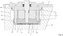
- FIG 5 shows the pump in the assembled state, the pump as such again in section AA of Figure 3 is shown.
- the pump is arranged on a receiving device 15.
- the arrangement is such that the pump protrudes with the bead seal S first into a receiving shaft 16 of the receiving device 15.
- the pump rests with the mounting flange of the end wall 4 on the receiving device 15 and is fastened to the receiving device 15 in the region of the flange, for example by means of a screw connection.
- the pump protrudes with its connection side first into the receiving shaft 16, so that the outer end face of the end wall 3 is a base 17 of the receiving shaft 16 at a small axial distance, i. H. via an axial joint.
- the spring device 40 is supported in the assembled state of the pump axially on the shaft bottom 17 and acts with its spring force axially on the end wall 3.
- the spring device 40 presses in this way with spring force the end wall 3 against the peripheral wall 2 and this against the end wall 4, whereby an axially denser and firmer
- the composite of the end walls 3 and 4 and the peripheral wall 2 are preserved and the sealing of the delivery chamber 5 ( Figure 1 ) is guaranteed.
- a low-pressure chamber 16a is formed, which is delimited radially on the outside by an inner circumferential wall of the receiving shaft 16 and axially by the sealing rings 14a and 14b.
- the fluid passes through the low-pressure chamber 16a and the inlets 6 and 7 opening into the low-pressure chamber 16a ( Figures 1 and 2 ) into the delivery chamber 5 ( Figure 1 ).
- connection channels 8 and 9 open into the associated pressure outlets, the connection channel 8 in the first pressure outlet and the connection channel 9 in the second pressure outlet.
- the first pressure outlet is therefore referred to below as pressure outlet 8 and the second pressure outlet as pressure outlet 9.
- the pressure outlets 8 and 9 extend axially through the end wall 3 and each open into a recess on the outer end face of the end wall 3.
- the first pressure outlet 8 of the pump lies axially opposite the first pressure connection 18.
- the second pressure outlet 9 of the pump lies opposite the second pressure connection 19.
- the fluid of the first working flow is conveyed away via the first pressure outlet 8 and the first pressure connection 18.
- the fluid of the second working flow is conveyed away via the second pressure outlet 9 and the second pressure connection 19.
- the outlet seal S is arranged in the axial joint remaining between the end wall 3 and the shaft bottom 17 and separates the first pressure outlet 8 and first pressure connection 18 from the second pressure outlet 9 and second pressure connection 19.
- FIG. 6 is a longitudinal section which runs through the central passage 35 of the bead seal S, which is used to hold the end wall 3.
- FIG. 11 is an enlarged illustration of a portion of the longitudinal section of FIG Figure 6 .
- Figure 8 is an isometric view of that facing away from the end wall 3 in the preassembled and assembled state of the pump Outside of the bead seal p.
- Figure 9 shows the bead seal S also in an isometric view, but cut lengthways.
- the bead seal S comprises a first bead loop 21 which surrounds a first inner region 22.
- the bead loop 21 is a smallest bead loop with respect to the inner area 22, which encloses the inner area 22 in an axial plan view, ie completely surrounds it.
- the bead loop 21 is a half bead, as in particular in FIG Figure 7 , but also in the full longitudinal section of the Figure 6 and in Figure 9 is recognizable.
- the first bead loop 21 is stiffened in the inner area 22 in comparison to conventional bead loops.
- the stiffening is achieved by means of a first stiffening structure 24 which extends circumferentially from the inner edge of the beading loop 21 into the inner region 22.
- the stiffening structure 24 is shaped as a flat, thin disk. It has a plurality of passages 23 arranged next to one another, through which the fluid can flow when the pump is in operation.
- the stiffening structure 24 extends along the entire inner circumference of the beading loop 21 and stiffens the beading loop 21 radially inwards uniformly over the entire inner circumference.
- the passages 23 are circular through bores, but in modifications can also have fundamentally different cross-sectional shapes, for example elongated, straight or curved slots.
- the bead seal S also has the already in the Figures 2 and 3 recognizable further, second beading loop 25 which surrounds the second inner region 26 in the axial view.
- the beading loop 25 forms a smallest beading loop in relation to the inner region 26, which in the axial view encloses the inner region 26, ie completely surrounds it.
- the second bead loop 25 is a full bead.
- the beading loop 25 is also stiffened in its inner area 26.
- a second stiffening structure 28 is used for stiffening, which like the first stiffening structure 24 is shaped as a flat, thin disk.
- the stiffening structure 28 also extends uniformly over the entire inner circumference of the bead loop 25 in order to stiffen it radially inward over the inner circumference.
- the second stiffening structure 28 is also provided with a plurality of passages 27 arranged next to one another for the fluid conveyed by the pump.
- the passages 27 are also shaped as circular through bores, can in However, modifications also have other cross-sectional shapes, for example as elongated, straight slots or elongated, curved slots.
- the first beading loop 21 and the second beading loop 25 are arranged next to one another in the axial view, so that the associated inner regions 22 and 26 are also arranged next to one another and at a distance from one another.
- the loops 21 and 25 also run separately at a distance from one another.
- the central passage 35 which serves to center the bead seal S on the pump housing 1.
- the bead seal S also includes those already in the Figures 2 and 3 recognizable further, third beading loop 31 which surrounds the further, third inner region 32.
- the bead loop 31 is a smallest bead loop with respect to the inner region 32, which encloses the inner region 32 in the axial view, that is to say completely surrounds it.
- the beading loop 31 is stiffened radially inwards in a manner comparable to that of the beading loop 21.
- a third stiffening structure 34 which is shaped as a flat, thin disk, is used for stiffening.
- the third stiffening structure 34 corresponds to the first stiffening structure 24 and, like these, has passages 33 for the fluid.
- passages 33 With regard to the passages 33, what has been said about the passages 23 applies in the same way.
- the passages 33 are in axial alignment with the passages 23, so that the fluid can flow through the bead seal S in the axial direction over the shortest possible path in the area of the two inner regions 22 and 32.
- the passages 33 can also be offset in the radial direction with respect to the passages 23 in order to increase the flow resistance for the fluid while the shape and number of the passages 22 and 33 are otherwise the same.
- the third bead loop 31 is shaped like the first bead loop 21 as a half bead.
- the bead loops 21 and 31 spread away from one another starting from their outer circumference in the axial direction towards the inner areas 22 and 32, whereby the axial spring travel of the bead seal S in the area of the bead loops 21 and 31 is increased compared to the respective individual bead 21 and 31.
- the increase in the axial spring travel is advantageous with regard to the desired compensation for variations in the axial width of the joint to be sealed.
- the bead seal S is multilayered. It comprises a first gasket layer 20 and a second gasket layer 30.
- the first bead loop 21 and the first stiffening structure 24 are part of the first gasket layer 20.
- the second gasket layer 30 forms the third gasket bead 31 and the third stiffening structure 34.
- the gasket layers 20 and 30 are directly on each other. They can advantageously be joined to one another in a materially bonded manner, for example by means of a welded or soldered connection or an adhesive connection.
- the first sealing layer 20 also forms the second bead loop 25 and its stiffening structure 28.
- the sealing layers 20 and 30 are sheet metal structures.
- it can be sheet steel structures and preferably spring steel structures.
- the sheet metal structures can also be plastic structures, for example so-called organic sheet structures.
- sheet steel is preferred.
- the bead seal S has outwardly protruding tabs 29 on the outer circumference, which serve to position the bead seal S relative to the pump housing 1 and interact with corresponding positioning elements of the pump housing 1, for example axial projections on the end wall 3.
- the tabs 29 can form a fitting connection with the end wall 3 or engage with the end wall 3 in a form-fitting manner, preferably without friction.
- the tabs 29 also serve to hold the pump housing 1.
- the tabs 29 can be screwed, soldered, welded, glued, etc. to the end wall 3, for example. In the exemplary embodiment, however, the tabs 29 engage behind the spring device 40, so that the bead seal S is held centered and positioned in the rear engagement of the spring device 40 on the pump housing 1.
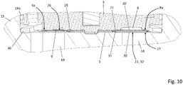
- Figure 10 shows an enlarged view of the area of the axial joint between the end wall 3 and the shaft bottom 17.
- the bead seal S is arranged in the joint and separates the first pressure outlet 8 and first pressure connection 18 from the second pressure outlet 9 and second pressure connection 19.
- the first bead loop 21 encloses the first pressure outlet 8 fluid-tight.
- the third bead loop 31 encloses the first pressure connection 18 in a fluid-tight manner.
- the first pressure outlet 8 opens, as already mentioned, in a recess on the outer end face of the end wall 3
- the depression is assigned to the first pressure outlet 8 and is therefore also designated with the reference symbol 8.
- the first beading loop 21 encloses the depression of the first pressure outlet 8 in a fluid-tight manner.
- the first beading loop 21 rests in a sealing manner on a peripheral edge 8a of the depression, ie the first pressure outlet 8.
- the circumferential edge 8a encloses the first pressure outlet 8, in the exemplary embodiment it encloses its recess on the outer end face of the end wall 3, at which the pressure outlet 8 opens.
- the third bead loop 31 lies against the peripheral edge of the first pressure connection 18 formed by the shaft bottom 17 in a sealing manner.
- the bead loops 21 and 31 each press with an axial spring force against the associated peripheral edge 8a and 17.
- the bead seal S is advantageously installed with an axial pretensioning force.
- the pretensioning force is expediently chosen so that it is effective under all installation conditions, i. H.
- a spring force sufficient for tightness is guaranteed.
- the bead seal S is designed in the area of the bead loops 21 and 31 so that it can compensate for variations in the axial joint width of at least 0.1 mm or at least 0.2 mm, preferably 0.3 mm or more, i.e. H. A sufficient seal is guaranteed over the respective range of variation of the axial joint width.
- the second bead loop 25 can be designed so that it rests in a sealing manner on a peripheral edge 9a surrounding the second pressure outlet 9 and at the same time on the axially opposite shaft bottom 17, there surrounding the second pressure connection 19.
- the second bead loop 25, when the pump is installed only rests on the outer end of the end wall 3, ie on the circumferential edge 9a mentioned, with a certain pretensioning force, but has no contact or at least no sealing contact with the shaft bottom 17. It is advantageous if the bead seal S presses against the peripheral edge 9a on the outer end face of the end wall 3 with a certain axial prestressing force in the assembled state of the pump.
- the first pressure outlet 8 and the first pressure connection 18 are separated by the first beading loop 21 and third beading loop 31.
- the separation from the low-pressure side of the pump, in particular from the low-pressure chamber 16a ( Figure 5 ) is guaranteed by the sealing ring 14b.
- the inner areas 22 and 32 of the corrugated seal S lie axially opposite the first pressure outlet 8 and first pressure connection 18 and with its inner area 26 the second pressure outlet 9 and second pressure connection 19.
- the inner areas 22 and 32 cover the first pressure outlet 8 and first pressure connection 18.
- the inner area 26 covers the second pressure outlet 9 and second pressure connection 19.
- the inner areas 22 and 32 cover the recess to which the pressure outlet 8 on the outer end face of the Front wall 3 widened.
- the inner region 26 covers the recess to which the pressure outlet 9 widens on the outer end face of the end wall 3.
- the fluid is conveyed through the pressure outlets 8 and 9 and distributed in the area of the respective associated depression over the inner areas 22, 32 and 26 enclosed by the beading loops 21, 31 and 25.
- the pressurized fluid then flows through the local passages 23, 33 and 27 in the respective stiffening structure 24, 34 and 28 ( Figure 9 ) and flows off via the subsequent pressure connection 18 and 19.
- the stiffening structures with their passages ensure that the flow is evened out; in particular, they ensure a reduction in pressure peaks in the cold operating state and a correspondingly viscous fluid.
- the stiffening structures provide a flow resistance so that the lower wing grooves are quickly supplied with the pressure fluid during a cold start.
- the bead seal S can be under an axial pretensioning force, so that it is elastically axially compressed and exerts an axial spring force on the pump housing 1 in accordance with the pretensioning force.
- the bead seal S can be arranged in a force shunt to a restoring device.
- the restoring device preferably absorbs the major part of the axial force acting across the joint when the joint width is reduced.
- the bead seal S can in particular be arranged in a force shunt with an axially acting spring device.
- the bead seal S is arranged in a force shunt with the spring device 40.
- the bead seal S can alternatively also be arranged in a force main connection and exert an axial spring force on the pump housing 1 alone, that is to say take over the function of the spring device 40 and replace it.
- the stiffened bead seal S is compared to a non-stiffened bead seal (comparative seal).
- F 1 denotes the path-dependent force curve of the bead seal S in the area of the first bead loop 21 and third bead loop 31.
- F 2 denotes the path-dependent force curve of the comparison seal.
- the comparative seal corresponds as such to the bead seal S, but has no stiffening structure that protrudes into the flow cross-section of the fluid in the pre-assembled or assembled state of the pump and thus protrudes into and from the fluid during pump operation is flowed against.
- the respective bead seal is unloaded in its initial state, ie no force other than gravity acts on it.
- the comparative seal opposes an axial compression over a range of a few tenths of a millimeter with a comparatively low spring force and kinks practically suddenly with a certain reduction in its axial width.
- the stiffened bead seal S can be installed with an axial prestressing force that is at least as great as a minimum spring force required to ensure tightness and greater than the spring force at which the comparison seal buckles when it is reached.
- the minimum spring force is expediently based on a largest axial joint width, which can be set due to the installation tolerances and operational requirements. However, variations in the joint width that occur during operation due to temperature changes and pressure pulsations are significantly smaller than the variations resulting from the tolerance chains from pump to pump.
- the pre-tensioning force guarantees that at least the minimum spring force acts on the beading loops 21 and 31 with the largest joint width.
- the pretensioning force is advantageously chosen so that the gradient of the force-versus-travel curve is less than 45 ° or less than 30 °.
- the stiffened bead seal S has a comparatively large area in which the axial joint width can vary, but the bead seal S still does not lose its spring effect, i.e. is only slightly plastically deformed, and always with sufficient spring force against the circumferential edge to be sealed , in the exemplary embodiment against the peripheral edge 9a and the shaft bottom 17 ( Fig. 10 ), presses.
Landscapes
- Engineering & Computer Science (AREA)
- General Engineering & Computer Science (AREA)
- Mechanical Engineering (AREA)
- Physics & Mathematics (AREA)
- Fluid Mechanics (AREA)
- Gasket Seals (AREA)
Applications Claiming Priority (1)
| Application Number | Priority Date | Filing Date | Title |
|---|---|---|---|
| DE102019132729.6A DE102019132729A1 (de) | 2019-12-02 | 2019-12-02 | Sickendichtung |
Publications (1)
| Publication Number | Publication Date |
|---|---|
| EP3832175A1 true EP3832175A1 (fr) | 2021-06-09 |
Family
ID=73597792
Family Applications (1)
| Application Number | Title | Priority Date | Filing Date |
|---|---|---|---|
| EP20209537.8A Pending EP3832175A1 (fr) | 2019-12-02 | 2020-11-24 | Joint d'étanchéité de moulure |
Country Status (4)
| Country | Link |
|---|---|
| US (1) | US12467443B2 (fr) |
| EP (1) | EP3832175A1 (fr) |
| CN (1) | CN112983822B (fr) |
| DE (1) | DE102019132729A1 (fr) |
Cited By (2)
| Publication number | Priority date | Publication date | Assignee | Title |
|---|---|---|---|---|
| EP4012233A1 (fr) * | 2020-12-11 | 2022-06-15 | Schwäbische Hüttenwerke Automotive GmbH | Joint d'étanchéité de moulure |
| US11719242B2 (en) | 2020-06-25 | 2023-08-08 | Schwäbische Hüttenwerke Automotive GmbH | Axial pressure relief in slide bearings of pumps |
Families Citing this family (2)
| Publication number | Priority date | Publication date | Assignee | Title |
|---|---|---|---|---|
| DE102021126416A1 (de) * | 2021-10-12 | 2023-04-13 | Schwäbische Hüttenwerke Automotive GmbH | Axialsicherung einer Pumpe |
| CN114893419B (zh) * | 2022-05-23 | 2023-05-23 | 烟台东德实业有限公司 | 一种燃料电池单级高速离心空压机与膨胀机集成系统 |
Citations (14)
| Publication number | Priority date | Publication date | Assignee | Title |
|---|---|---|---|---|
| US3050010A (en) * | 1960-02-23 | 1962-08-21 | Thompson Ramo Wooldridge Inc | Pressure loaded pump |
| DE4219709A1 (de) | 1992-06-16 | 1994-02-03 | Reinz Dichtungs Gmbh | Metallische Flachdichtung |
| US6098597A (en) * | 1999-09-07 | 2000-08-08 | Navistar International Transportation Corp | Hydraulic system with a combination filter screen and gasket |
| WO2001094791A1 (fr) | 2000-06-08 | 2001-12-13 | Luk Fahrzeug-Hydraulik Gmbh & Co. Kg | Pompe |
| US20070157800A1 (en) * | 2004-03-16 | 2007-07-12 | Hargraves Technology Corporation | Pump sealing apparatus |
| DE102009010385A1 (de) * | 2009-02-26 | 2010-09-16 | Elringklinger Ag | Siebeinrichtung |
| EP2378169A1 (fr) * | 2008-12-26 | 2011-10-19 | Nippon Gasket Co., Ltd. | Structure de joint pour un trou de goutte d'huile dans un joint de culasse |
| DE102010028899A1 (de) * | 2010-05-11 | 2011-11-17 | Schwäbische Hüttenwerke Automotive GmbH | Dichtung mit Niederhalter |
| US20140008877A1 (en) * | 2011-03-08 | 2014-01-09 | Nok Corporation | Seal bead structure of gasket |
| US20140346106A1 (en) * | 2012-01-25 | 2014-11-27 | Nok Corporation | Metal substrate gasket with filter function and manufacturing method therefor |
| DE202014005866U1 (de) * | 2014-07-18 | 2015-07-22 | Reinz-Dichtungs-Gmbh | Metallische Flachdichtung |
| EP3081741A2 (fr) | 2015-04-17 | 2016-10-19 | Schwäbische Hüttenwerke Automotive GmbH | Pompe |
| US9518659B2 (en) * | 2011-04-07 | 2016-12-13 | Reinz-Dichtungs-Gmbh | Flat gasket with calendered sieve layer |
| US20170260979A1 (en) | 2016-03-11 | 2017-09-14 | Magna Powertrain Bad Homburg GmbH | Seal arrangement for a switchable vane cell pump of cartridge design |
Family Cites Families (14)
| Publication number | Priority date | Publication date | Assignee | Title |
|---|---|---|---|---|
| US1851948A (en) * | 1927-03-31 | 1932-03-29 | Frigidaire Corp | Gasket |
| US3523746A (en) | 1968-10-31 | 1970-08-11 | Racine Hydraulics Inc | Fluid translating device |
| EP0758716B1 (fr) | 1995-08-14 | 2003-12-10 | LuK Fahrzeug-Hydraulik GmbH & Co. KG | Pompe à palettes |
| DE69634031D1 (de) * | 1995-11-07 | 2005-01-20 | Nicholsons Aircraft Seals Ltd | Abdichtung |
| EP0775856A1 (fr) * | 1995-11-23 | 1997-05-28 | TAKO PAYEN S.p.a. | Joint d'étanchéité pour tuyau d'échappement de gaz de combustion |
| DE10310124B4 (de) * | 2003-03-07 | 2009-09-10 | Continental Automotive Gmbh | Flachdichtung |
| JP2010519016A (ja) * | 2007-02-16 | 2010-06-03 | インテグリス・インコーポレーテッド | 重合系膜及び金属支持体を有する流体フィルタ |
| JP5022139B2 (ja) | 2007-08-17 | 2012-09-12 | 日立オートモティブシステムズ株式会社 | 可変容量型ベーンポンプ |
| ITMI20072300A1 (it) * | 2007-12-06 | 2009-06-07 | Bosch Gmbh Robert | Guarnizione per pompa di alta pressione e pompa di alta pressione comprendente tale guarnizione |
| US8459656B2 (en) * | 2009-10-20 | 2013-06-11 | Robert K Ridgway | Fuel line gasket for use with a diesel fuel injector |
| JP5764453B2 (ja) * | 2011-10-03 | 2015-08-19 | カヤバ工業株式会社 | ベーンポンプ |
| DE202016106106U1 (de) | 2016-10-31 | 2018-02-12 | Reinz-Dichtungs-Gmbh | Flachdichtung und Verbrennungsmotor |
| JP6408659B1 (ja) | 2017-07-18 | 2018-10-17 | 石川ガスケット株式会社 | ガスケット |
| CN107131123A (zh) | 2017-07-21 | 2017-09-05 | 世特科汽车工程产品(常州)有限公司 | 一种双排量叶片泵 |
-
2019
- 2019-12-02 DE DE102019132729.6A patent/DE102019132729A1/de active Pending
-
2020
- 2020-11-18 US US16/951,488 patent/US12467443B2/en active Active
- 2020-11-24 EP EP20209537.8A patent/EP3832175A1/fr active Pending
- 2020-12-01 CN CN202011388362.4A patent/CN112983822B/zh active Active
Patent Citations (14)
| Publication number | Priority date | Publication date | Assignee | Title |
|---|---|---|---|---|
| US3050010A (en) * | 1960-02-23 | 1962-08-21 | Thompson Ramo Wooldridge Inc | Pressure loaded pump |
| DE4219709A1 (de) | 1992-06-16 | 1994-02-03 | Reinz Dichtungs Gmbh | Metallische Flachdichtung |
| US6098597A (en) * | 1999-09-07 | 2000-08-08 | Navistar International Transportation Corp | Hydraulic system with a combination filter screen and gasket |
| WO2001094791A1 (fr) | 2000-06-08 | 2001-12-13 | Luk Fahrzeug-Hydraulik Gmbh & Co. Kg | Pompe |
| US20070157800A1 (en) * | 2004-03-16 | 2007-07-12 | Hargraves Technology Corporation | Pump sealing apparatus |
| EP2378169A1 (fr) * | 2008-12-26 | 2011-10-19 | Nippon Gasket Co., Ltd. | Structure de joint pour un trou de goutte d'huile dans un joint de culasse |
| DE102009010385A1 (de) * | 2009-02-26 | 2010-09-16 | Elringklinger Ag | Siebeinrichtung |
| DE102010028899A1 (de) * | 2010-05-11 | 2011-11-17 | Schwäbische Hüttenwerke Automotive GmbH | Dichtung mit Niederhalter |
| US20140008877A1 (en) * | 2011-03-08 | 2014-01-09 | Nok Corporation | Seal bead structure of gasket |
| US9518659B2 (en) * | 2011-04-07 | 2016-12-13 | Reinz-Dichtungs-Gmbh | Flat gasket with calendered sieve layer |
| US20140346106A1 (en) * | 2012-01-25 | 2014-11-27 | Nok Corporation | Metal substrate gasket with filter function and manufacturing method therefor |
| DE202014005866U1 (de) * | 2014-07-18 | 2015-07-22 | Reinz-Dichtungs-Gmbh | Metallische Flachdichtung |
| EP3081741A2 (fr) | 2015-04-17 | 2016-10-19 | Schwäbische Hüttenwerke Automotive GmbH | Pompe |
| US20170260979A1 (en) | 2016-03-11 | 2017-09-14 | Magna Powertrain Bad Homburg GmbH | Seal arrangement for a switchable vane cell pump of cartridge design |
Cited By (2)
| Publication number | Priority date | Publication date | Assignee | Title |
|---|---|---|---|---|
| US11719242B2 (en) | 2020-06-25 | 2023-08-08 | Schwäbische Hüttenwerke Automotive GmbH | Axial pressure relief in slide bearings of pumps |
| EP4012233A1 (fr) * | 2020-12-11 | 2022-06-15 | Schwäbische Hüttenwerke Automotive GmbH | Joint d'étanchéité de moulure |
Also Published As
| Publication number | Publication date |
|---|---|
| CN112983822B (zh) | 2023-08-08 |
| CN112983822A (zh) | 2021-06-18 |
| US12467443B2 (en) | 2025-11-11 |
| US20210164460A1 (en) | 2021-06-03 |
| DE102019132729A1 (de) | 2021-07-01 |
Similar Documents
| Publication | Publication Date | Title |
|---|---|---|
| EP3832175A1 (fr) | Joint d'étanchéité de moulure | |
| DE102011084059B4 (de) | Steuerventil mit integriertem Filter und Nockenwellen-Phasensteller mit dem Steuerventil | |
| EP3263835B1 (fr) | Pompe à palettes comprenant une zone d'aile inférieure pressurisable | |
| EP2337928B1 (fr) | Pompe, notamment pompe à palettes | |
| EP3409897B1 (fr) | Agencement d'étanchéité pour une turbomachine, méthode de fabrication de l'agencement d'étanchéité et turbomachine | |
| EP3489474A1 (fr) | Régulateur de phase d'arbre à cames pourvu de clapet anti-retour de type anneau | |
| EP2754896B1 (fr) | Pompe à gaz avec détente pour la réduction du couple de démarrage | |
| DE102010019530A1 (de) | Nockenwellenversteller und U-förmiges Dichtelement zum Abdichten einer radialen Fläche eines Flügels eines Nockenwellenverstellers | |
| WO2020136269A1 (fr) | Pompe rotative à compensation axiale, garniture d'étanchéité de sortie pour une pompe et ensemble pompe prémonté | |
| EP3333381B1 (fr) | Dispositif hydraulique comprenant un élément d'étanchéité | |
| EP2743506B1 (fr) | Pompe à gaz dotée d'une rainure à huile d'étanchéification | |
| EP3929439A1 (fr) | Décharge axiale de pression dans les paliers lisses des pompes | |
| EP2815129B1 (fr) | Agencement de joint et pompe dotée d'un agencement de joint | |
| EP3903005A1 (fr) | Pompe rotative avec compensation axiale, garniture d'étanchéité de sortie pour une pompe ainsi qu'unité de pompe préassemblée | |
| EP3903006A1 (fr) | Pompe rotative à compensation axiale, garniture d'étanchéité de sortie pour une pompe et ensemble pompe prémonté | |
| DE102019103675A1 (de) | Feder-Dichtungs-Einheit | |
| EP3929400A1 (fr) | Pompe pourvu d'élément d'étanchéité à ressort axial efficace | |
| EP1721095A1 (fr) | Dispositif d'etancheite pour un moteur pivotant radial | |
| EP4012233A1 (fr) | Joint d'étanchéité de moulure | |
| DE102013203521A1 (de) | Dichtungsanordnung eines Abgasturboladers, sowie Turboladerwelle für einen Abgasturbolader | |
| AT505061B1 (de) | Drehschieberpumpe | |
| DE102013215361A1 (de) | Dichtungsanordnung | |
| DE102019127388A1 (de) | Fluidversorgung von Unterflügelkammern einer Flügelzellenpumpe | |
| WO2016173799A1 (fr) | Dispositif pompe | |
| DE102013207473A1 (de) | Abgasturbolader mit Gehäusen, die mittels einer Pressverbindung miteinander verbunden sind |
Legal Events
| Date | Code | Title | Description |
|---|---|---|---|
| PUAI | Public reference made under article 153(3) epc to a published international application that has entered the european phase |
Free format text: ORIGINAL CODE: 0009012 |
|
| STAA | Information on the status of an ep patent application or granted ep patent |
Free format text: STATUS: THE APPLICATION HAS BEEN PUBLISHED |
|
| AK | Designated contracting states |
Kind code of ref document: A1 Designated state(s): AL AT BE BG CH CY CZ DE DK EE ES FI FR GB GR HR HU IE IS IT LI LT LU LV MC MK MT NL NO PL PT RO RS SE SI SK SM TR |
|
| RAP3 | Party data changed (applicant data changed or rights of an application transferred) |
Owner name: SCHWAEBISCHE HUETTENWERKE AUTOMOTIVE GMBH |
|
| STAA | Information on the status of an ep patent application or granted ep patent |
Free format text: STATUS: REQUEST FOR EXAMINATION WAS MADE |
|
| 17P | Request for examination filed |
Effective date: 20211112 |
|
| RBV | Designated contracting states (corrected) |
Designated state(s): AL AT BE BG CH CY CZ DE DK EE ES FI FR GB GR HR HU IE IS IT LI LT LU LV MC MK MT NL NO PL PT RO RS SE SI SK SM TR |
|
| STAA | Information on the status of an ep patent application or granted ep patent |
Free format text: STATUS: EXAMINATION IS IN PROGRESS |
|
| 17Q | First examination report despatched |
Effective date: 20230906 |