EP3832186B1 - Système de raccordement pourvu de marquage de séparation - Google Patents
Système de raccordement pourvu de marquage de séparation Download PDFInfo
- Publication number
- EP3832186B1 EP3832186B1 EP20208544.5A EP20208544A EP3832186B1 EP 3832186 B1 EP3832186 B1 EP 3832186B1 EP 20208544 A EP20208544 A EP 20208544A EP 3832186 B1 EP3832186 B1 EP 3832186B1
- Authority
- EP
- European Patent Office
- Prior art keywords
- main pipe
- connection system
- installation insert
- end section
- insert
- Prior art date
- Legal status (The legal status is an assumption and is not a legal conclusion. Google has not performed a legal analysis and makes no representation as to the accuracy of the status listed.)
- Active
Links
Images

Classifications
-
- F—MECHANICAL ENGINEERING; LIGHTING; HEATING; WEAPONS; BLASTING
- F16—ENGINEERING ELEMENTS AND UNITS; GENERAL MEASURES FOR PRODUCING AND MAINTAINING EFFECTIVE FUNCTIONING OF MACHINES OR INSTALLATIONS; THERMAL INSULATION IN GENERAL
- F16L—PIPES; JOINTS OR FITTINGS FOR PIPES; SUPPORTS FOR PIPES, CABLES OR PROTECTIVE TUBING; MEANS FOR THERMAL INSULATION IN GENERAL
- F16L41/00—Branching pipes; Joining pipes to walls
- F16L41/08—Joining pipes to walls or pipes, the joined pipe axis being perpendicular to the plane of a wall or to the axis of another pipe
- F16L41/088—Joining pipes to walls or pipes, the joined pipe axis being perpendicular to the plane of a wall or to the axis of another pipe fixed using an elastic grommet between the extremity of the tube and the wall
-
- F—MECHANICAL ENGINEERING; LIGHTING; HEATING; WEAPONS; BLASTING
- F16—ENGINEERING ELEMENTS AND UNITS; GENERAL MEASURES FOR PRODUCING AND MAINTAINING EFFECTIVE FUNCTIONING OF MACHINES OR INSTALLATIONS; THERMAL INSULATION IN GENERAL
- F16L—PIPES; JOINTS OR FITTINGS FOR PIPES; SUPPORTS FOR PIPES, CABLES OR PROTECTIVE TUBING; MEANS FOR THERMAL INSULATION IN GENERAL
- F16L41/00—Branching pipes; Joining pipes to walls
- F16L41/002—Branching pipes; Joining pipes to walls of concrete, cement or asbestos-cement
-
- F—MECHANICAL ENGINEERING; LIGHTING; HEATING; WEAPONS; BLASTING
- F16—ENGINEERING ELEMENTS AND UNITS; GENERAL MEASURES FOR PRODUCING AND MAINTAINING EFFECTIVE FUNCTIONING OF MACHINES OR INSTALLATIONS; THERMAL INSULATION IN GENERAL
- F16L—PIPES; JOINTS OR FITTINGS FOR PIPES; SUPPORTS FOR PIPES, CABLES OR PROTECTIVE TUBING; MEANS FOR THERMAL INSULATION IN GENERAL
- F16L2201/00—Special arrangements for pipe couplings
- F16L2201/60—Identification or marking
-
- F—MECHANICAL ENGINEERING; LIGHTING; HEATING; WEAPONS; BLASTING
- F16—ENGINEERING ELEMENTS AND UNITS; GENERAL MEASURES FOR PRODUCING AND MAINTAINING EFFECTIVE FUNCTIONING OF MACHINES OR INSTALLATIONS; THERMAL INSULATION IN GENERAL
- F16L—PIPES; JOINTS OR FITTINGS FOR PIPES; SUPPORTS FOR PIPES, CABLES OR PROTECTIVE TUBING; MEANS FOR THERMAL INSULATION IN GENERAL
- F16L25/00—Construction or details of pipe joints not provided for in, or of interest apart from, groups F16L13/00 - F16L23/00
- F16L25/14—Joints for pipes of different diameters or cross-section
Definitions
- the invention relates to a connection system for connecting a pipe to a main pipe. Furthermore, the invention relates to a pipe system that is equipped with such a connection system.
- connection of a pipe to a main pipe is a common case when, for example, residential areas are developed and sewage pipes from individual houses or apartment blocks are to be connected to a main pipe.
- This requires connection systems that are easy to install, have the tightness required for this purpose and are inexpensive.
- such a subsequent installation on a main pipe is a job that should be done as simply as possible from a cost perspective, in order to minimize the excavation for the excavation pit, but still create a practicable - but above all durable and tight - connection.
- the aforesaid proven technology reaches its limits when there is a main pipe made of concrete that is steel-reinforced. With such a main pipe, the steel reinforcement in the area of the transverse opening to be produced is inevitably exposed. This can rust under the influence of moisture and oxygen, which can lead to damage or even partial destruction of the main pipe.
- a connection system for connecting a pipe to such a main pipe in particular to a main pipe made of steel-reinforced concrete, must therefore not only ensure tightness at the transverse opening, but also prevent moisture and oxygen from penetrating into the gap between the inner surface of the main pipe and the connection system , so as to protect the reinforcement from rusting and subsequent damage or destruction of the main pipe.
- Another object of the invention is to specify a pipe system that includes a connection system.
- the first task is solved according to claim 1.
- connection system for connecting a pipe to a main pipe, a shaft, or the like, at a transverse opening, the connection system being connectable to the main pipe or the shaft for this purpose, with a hollow plug-shaped, at least partially soft installation insert, the outside of which is adapted to the transverse opening, and the inside of which has a conical screw area, the installation insert having an end section which can be partially inserted through the transverse opening of the main pipe or shaft into this / these, and an outer contact surface of the installation insert in a connection state in which the connection system is connected to the main pipe or manhole, at least partially contacts a main pipe inner surface which abuts and surrounds the transverse opening, and a relatively harder spigot which has an engaging end, a conical center has an external thread and a drive end, solves this problem if it is provided according to the invention that at least one separating marking is formed on the end section, which is formed running at least partially around the outer circumference of the end section,
- connection system With the help of this connection system, it is possible to create a complete seal between the connected pipe and the main pipe, and in particular a main pipe made of steel-reinforced concrete.
- connection system it is possible to provide a solution that is as universal as possible, ie one that covers a large pipe wall thickness range, for connecting a pipe to a main pipe or a shaft or the like.
- the end section of the installation insert which is initially produced with an oversize in terms of the length of the end section, can be shortened as required along the separation mark in such a way that, in any case, when installing the connection system, the exposed steel reinforcement of the main pipe made of steel-reinforced concrete is protected from the influence protected from moisture and oxygen.
- the end section of the initially overlong installation insert can easily be shortened to the required length, the length of the end section then having to be selected so that all exposed reinforcements are covered during installation.
- Such a connection system according to the invention is significantly improved over the prior art as far as the protection of the steel reinforcement of the main pipe is concerned, it is simple to manufacture, inexpensive to provide and install without any special effort, and it is highly fluid-tight.
- connection system is designed in such a way that a plurality of separation markings is arranged on the end section of the installation insert.
- the installing personnel can easily select the appropriate severing mark along which to separate the end portion of the installation insert as needed.
- connection system a number of 2, 3, 4, 5, 6, 7 or 8 separating markings are arranged on the end section of the installation insert.
- the present invention may be further enhanced by the termination system forming an array of the separator marks at the end portion of the installation insert, with at least one separator mark being equidistant from its respective nearest neighbors.
- connection system is designed in such a way that the separation marking is formed as a marking or as a cutting aid.
- connection system that is designed in such a way that the separation marking is formed as a marking or as a cutting aid offers a significant simplification for the installing personnel, since it is then easily recognizable along which line the end section of the installation insert is to be shortened in order to To form the shape of the inner surface of the main pipe in the area of the breakthrough adapted contour.
- a marking as a separation identifier can be implemented, for example, by colored printing.
- the cutting aid is designed as a groove or as a web, in particular as a groove or web running around the outer circumference of the end section.
- the cutting aid is designed as a groove or as a web, in particular as a groove or web running around the outer circumference of the end section, it is very easy to cut off the end section of the installation insert because the guidance of a cutting tool, such as a knife, is made possible in a simple manner by a groove or a ridge. Accidental slipping of the cutting tool can be prevented or reduced in this way, which has advantages in terms of precise cutting, error reduction, but also work safety.
- a groove or a web as a cutting aid can already be provided in a simple manner during the original shaping of the installation insert, in that these structures can already be formed by appropriate configurations in the tool for production.
- a sealing element is arranged on the end section of the installation insert preferably a sealing element that swells when exposed to water. This ensures that a high level of tightness is guaranteed in the area between the end section and the main pipe when the outer contact surface of the installation insert is in contact with the inner surface of the main pipe. This prevents water or moisture from entering the gap between the installation insert and the main pipe. Especially if the sealing element is a sealing element that swells when water enters, even small amounts of water or moisture cause the sealing element to swell, thereby increasing its volume and thus ensuring increased security against any leaks or backflow at this point.
- the sealing element can advantageously be accommodated in a receiving space provided for this purpose at the end section of the installation insert.
- a receiving space may be a recess formed along the outer periphery of the end portion of the installation insert into which the sealing member is insertable.
- a plurality of receiving spaces can be provided, so that the sealing element or sealing elements can be inserted into one or more of the receiving spaces.
- connection system can be designed in such a way that the connecting piece contains a polymer material or consists of a polymer material, the polymer material preferably being a thermoplastic, and particularly preferably a polyolefin, such as a polypropylene or a polyethylene or a polybutylene or a polyamide or a a copolymer of the foregoing, or a polyvinyl chloride and/or the plumbing insert includes or is made of an elastomeric polymeric material.
- the polymer material preferably being a thermoplastic, and particularly preferably a polyolefin, such as a polypropylene or a polyethylene or a polybutylene or a polyamide or a a copolymer of the foregoing, or a polyvinyl chloride
- the plumbing insert includes or is made of an elastomeric polymeric material.
- Connectors and installation insert made of polymer material or those containing a polymer material are durable, inert, stable, have a low weight, are easy to handle, easy to install and can be provided inexpensively.
- For plumbing inserts consisting of or containing an elastomeric polymeric material manufacture from rubber, styrene butadiene rubber (SBR), ethylene propylene diene rubber (EPDM), acrylonitrile butadiene rubber (NBR) , Thermoplastic Elastomer (TPE) or others.
- the installation insert can also be designed in two parts.
- an attachment piece which is approximately hollow-cylindrical and has an end that faces away from the interior of the main pipe, can be used by means of an attachment piece connection fluid-tight and firmly connected to a base part of the installation insert to this one.
- the endpiece can be formed, for example, from a polymeric material that has different properties than the base part of the installation insert.
- a pipe system is particularly favorable when it has at least one connection system, as described above.
- Such a pipe system is significantly improved over the prior art, especially with regard to the tightness and the protection of the exposed reinforcement of the main pipe.
- a pipe system is technically upgraded in a very special way by such a connection system according to the invention. This then results in the advantages described above.
- connection system is to be assembled as follows: First, a transverse opening is to be made in the main pipe using a known method; this can be done, for example, by a drilling process or a milling process. If the transverse opening has been made in the main pipe and if the edge of the transverse opening and the main pipe inner surface, which was created by the drilling or milling process and delimits the transverse opening, has been correspondingly smoothed, this is to be measured with regard to the wall thickness of the main pipe at the transverse opening.
- the end section of the installation insert is to be shortened according to the determined wall thickness of the main pipe at the transverse opening so that the end of the end section does not protrude beyond the inner edge of the transverse opening of the main pipe into the interior of the main pipe.
- a length indication provided on the outside of the installation insert can be used to cut off the end section.
- the cut to shorten the end section of the installation insert can be made easily with a cutting device, such as a knife, along the separation mark formed on the outer contact surface, e.g. along the groove, with the cutting device being securely guided through the groove.
- a cutting device such as a knife
- a cut is made in such a way that the end of the end section is then adapted to the shape of the inner surface of the main pipe, the shaft, or the like in the area of the transverse opening.
- connection system is completely leak-tight as the outer contact surface of the installation insert rests securely and tightly on the inner surface of the main pipe.
- connection system When this is done, the connection system is properly seated. In particular, all exposed reinforcements of the main pipe in the area of the transverse opening are covered and protected during installation.
- connection system according to the invention is significantly improved over the prior art as far as the protection of the steel reinforcement of the main pipe is concerned, it is simple to manufacture, inexpensive to provide and install without any special effort, and it is highly fluid-tight.
- the plumbing insert and fitting of the present invention can be made in a polymer molding process, such as an injection molding process, or a rotational molding process, or a rotational sintering process, or a pressing process, or a deep drawing process, or an extrusion blow molding process, or an additive manufacturing process, such as a 3D printing process, or a combination of the processes listed above be.
- a polymer molding process such as an injection molding process, or a rotational molding process, or a rotational sintering process, or a pressing process, or a deep drawing process, or an extrusion blow molding process, or an additive manufacturing process, such as a 3D printing process, or a combination of the processes listed above be.
- the installation insert and/or the connecting piece is/are produced in an additive manufacturing process, such as a 3D printing process.
- Such a process is suitable for producing an installation insert and/or a connecting piece according to the present invention in large quantities in a reproducible, dimensionally accurate and cost-effective manner.
- a three-dimensional model that can be read by a data processing machine can advantageously be used for the production.
- the invention also includes a method for generating a data processing machine-readable three-dimensional model for use in a manufacturing method for a service insert and/or a connecting piece.
- the method also includes in particular the input of data representing an installation insert and/or a connection piece into a data processing machine and the use of the data to represent an installation insert and/or a connection piece as a three-dimensional model, the three-dimensional model being suitable for Use in the manufacture of an installation insert and/or a connection piece.
- Also included in the method is a technique in which the input data is fed to one or more 3D scanners, which operate either in a touch or non-contact manner, with the latter emitting energy onto an installation insert and/or a fitting and receiving the reflected energy. and wherein a virtual three-dimensional model of a fitting insert and/or a fitting is created using computer-aided design software.
- the manufacturing process can be a generative powder bed process, in particular selective laser melting (SLM), selective laser sintering (SLS), selective heat sintering (Selective Heat Sintering - SHS), selective electron beam melting (Electron Beam Melting - EBM / Electron Beam Additive Manufacturing - EBAM) or solidification of powder material by means of a binder (binder jetting).
- SLM selective laser melting
- SLS selective laser sintering
- SHS selective heat sintering
- EBM / Electron Beam Additive Manufacturing - EBAM Electron Beam Additive Manufacturing - EBAM
- solidification of powder material by means of a binder binder jetting
- the manufacturing process can be a generative free space process, in particular build-up welding, wax deposition modeling (WDM), contour crafting, metal-powder application processes (MPA), plastic-powder application processes, cold gas spraying, electron beam melting (electron beam welding - EBW) or melt layering processes such as fused deposition Modeling (FDM) or Fused Filament Fabrication (FFF) include.
- the manufacturing process can include a generative liquid material process, in particular stereolithography (SLA), digital light processing (DLP), multi-jet modeling (MJM), polyjet modeling or liquid composite molding (LCM).
- the manufacturing method can include other generative layer construction methods, in particular Laminated Object Modeling (LOM), 3D screen printing or light-controlled electrophoretic deposition.
- LOM Laminated Object Modeling
- the invention is used wherever pipe systems are built from pipes or molded pipe parts, manholes and other components, in which a pipe is to be connected to a main pipe or manhole.
- the invention also includes sections with cross-sections of pipes or pipe fittings and components to be connected that deviate from the circular shape, for example elliptical, egg-shaped, angular, rounded-off angular or mixed forms of the aforementioned.
- the advantage of the present invention consists in particular in the fact that the structural measures described above result in a seal against the opening reveal of the opening, referred to here as the inner surface of the main pipe, with the exposed reinforcement of a steel-reinforced concrete main pipe being protected, so that there is a connection system that is improved over those of the prior art.
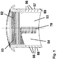
- FIG. 1 a schematic side sectional view of the installation insert 50 is shown in a first embodiment.
- the design of the installation insert 50 in the connection system 100 according to the invention is shown here in detail.
- the installation insert 50 is designed in one piece.
- the plumbing insert 50 includes an end portion 54.
- the end portion 54 of the plumbing insert 50 is that portion of the plumbing insert 50 that faces the interior of the main pipe 20 upon installation in the transverse opening 30 of the main pipe 20, which is shown in FIG 2 is shown in more detail.
- the installation insert 50 has an outer contact surface 57 with which it contacts the inner surface 23 of the main pipe in the connected state.
- sealing means and/or ribs combined with a specific choice of material, which can be soft or elastic, the tightness between the outer contact surface 57 of the installation insert 50 and the main pipe inner surface 23 of the main pipe 20 are made.
- a number of separation markings 55 are formed on the outer contact surface 57 of the installation insert 50 .
- the grooves 56 are formed along the entire outer circumference on the outer contact surface 57 of the installation insert 50 and are adapted to the shape of the inner surface 27 of the main pipe 20 in the area of the transverse opening 30, which will be explained later in FIG 2 is shown.
- the grooves 56 extend about 70 to 80% into the depth of the wall of the installation insert 50.
- the grooves 56 serve as a cutting aid to guide a cutting implement, such as a knife, to shorten the end portion 54 of the plumbing insert 50 as needed to conform it to the wall thickness of the main pipe 20.
- the end section 54 of the installation insert 50 can be cut along a groove 56 to such an extent that when the connection system 100 is installed it has the same or approximately the same length as the wall of the main pipe 20 is thick on the main pipe inner surface 23, which is shown in FIG 2 is shown.
- the separation marking 55 on the outer contact surface 57 of the installation insert 50 can also be a web, which is not shown here. Both a web and a groove 56 can easily be implemented in a simple manner during the manufacture of the installation insert 50 by appropriately designing the tool required for this purpose. A colored marking can be applied to the outer contact surface 57 of the installation insert 50 in a simple manner by printing.
- the length specification 70 applied to the inside of the installation insert 50 can be used as an aid for measuring the part of the end section 54 of the installation insert 50 to be cut off.
- the length indication 70 which is embossed on the inside of the installation insert 50, for example, after measuring the thickness of the wall of the main pipe 20 at the transverse opening 30, the part of the end section 54 of the installation insert 50 to be cut off can be determined immediately and the corresponding cut for separating the Part of the part of the end portion 54 of the installation insert 50 to be cut off.
- the end portion 54 of the installation insert 50 receiving spaces 58 are formed, for example in the form of a circumferential depression are shaped to receive a sealing member 59 there.
- the sealing element 59 is preferably a sealing element that swells when water enters.
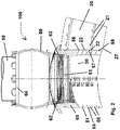
- connection system 100 In the 2 a schematic side sectional view of the connection system 100 is shown.
- connection system 100 is shown here in a connected state, in which a pipe 10 is connected to a main pipe 20 with the aid of the connection system 100, so that the pipe 10 opens into the main pipe 20 approximately perpendicularly.
- the main pipe 20 which is made of reinforced concrete, and here only on the right side of the
- the inner surface 27 delimits the lumen or interior of the main tube 20.
- a transverse opening 30 is made in the main pipe 20 and is delimited by an inner surface 23 of the main pipe.
- the transverse opening 30 is produced, for example, by a drilling process or a milling process.
- the transverse opening 30 preferably has a circular cross section, but can also be designed differently, and have an elliptical cross section, for example.
- the connection system 100 has an installation insert 50 which is in contact with the main pipe inner surface 23 with its outer contact surface 57 .
- the outer contact surface 57 of the installation insert 50 is profiled all the way around or at least partially all the way round or has a sealing element in order to ensure fluid-tight contact of the installation insert 50 in the transverse opening 30 on the main pipe inner surface 23 of the main pipe 20 .
- the end section 54 of the installation insert 50 is cut off along a groove 56 to such an extent that when the connection system 100 is in the installed state it has the same or approximately the same length as the wall of the main pipe 20 on the inner surface 23 of the main pipe is thick. In this way, those on the main pipe inner surface 23 of the main pipe 20 covered by the production of the transverse opening 30 exposed reinforcements 22 of the reinforcements 21 of the main pipe 20 of the outer contact surface 57 of the installation insert 50 and thus protected from the influence of moisture and oxygen.
- Such an installation insert 50 is formed in one piece and can be produced in a simple manner, for example in an injection molding process, from a polymer material and/or an elastomeric material such as rubber.
- the installation insert 50 provided for tightness can then be pressed towards the inner surface 23 of the main pipe, with the reinforcements 22 of the reinforcements 21 of the main pipe 20 exposed by the production of the transverse opening 30 being separated from the outer contact surface 57 of the installation insert 50 are covered. This protects them from the influence of moisture and oxygen.
- a connecting piece 60 with an external thread 63 is screwed into the screw region 52 on the inside 53 of the installation insert 50 .
- a drive end 64 of the connection piece 60 can be used to screw the external thread 63 of the connection piece 60 into the screw region 52 of the installation insert 50 .
- the connecting piece 60 has a conical middle part 62 which, when the connecting piece 60 is screwed into the installation insert 50 , ensures the necessary tightness between the outer contact surface 57 of the installation insert 50 and the main pipe inner surface 23 of the main pipe 20 .
- the connecting piece 60 is screwed into the installation insert 50 to such an extent that the installation insert 50 is correctly pressed in order to make the connection system 100 leak-tight.
- a specification is possible, such as such that the screwing in has to take place up to a mark on the connecting piece 60 or, for example, up to the last thread turn.
- connection system 100 If the connection system 100 has been installed correctly, the tightness is established so that the fluid can flow, for example, from the pipe 10 into the main pipe 20 without the fluid getting to undesired locations or possibly even to the outside into the environment. Fluid from the outside cannot get into the main pipe 20 or the connection system 100 in an undesired manner either.
- the tube 10 is at least partially pushed into the area of the drive end 64 of the connecting piece 60 .
- connection system 100 If the connection system 100 is properly installed, a fluid-tight connection between the connected pipe 10 and the main pipe 20 is produced in such a way that the outer contact surface 57 of the installation insert 50 is pressed by the compression by screwing in the connecting piece 60 in this area, the tightness is produced and the tightness against running behind or behind the outer contact surface 57 of the installation insert 50 is ensured.
- a receiving space 58 is formed on the end of the outer contact surface 57 of the installation insert 50 facing the inner surface 27 of the main pipe, in order to receive a sealing element 59 there.
- the sealing element 59 is preferably a sealing element 59 that swells when exposed to water.
- an installation insert 50 is shown in a second embodiment in a schematic lateral sectional view.
- the main pipe 20 which is made of reinforced concrete, and here only on the left side of the
- the installation insert 50 is formed in two parts.
- An extension piece 80 which is approximately hollow-cylindrical and has an end that faces away from the interior of the main pipe 20, is fluid-tightly and firmly connected to a base part 82 of the installation insert 50 by means of an attachment connection 81.
- the extension 80 can be formed, for example, from a polymeric material that has different properties than the base portion 82 of the installation insert 50.
- the outer surface of the extension 80 protects the exposed armor 22 of the armor 21 of the main pipe 20 from the effects of moisture and oxygen.
Landscapes
- Engineering & Computer Science (AREA)
- General Engineering & Computer Science (AREA)
- Mechanical Engineering (AREA)
- Quick-Acting Or Multi-Walled Pipe Joints (AREA)
- Joints With Sleeves (AREA)
Claims (9)
- Système de raccordement (100) pour raccorder un tuyau (10) à un tuyau principal (20), un puits ou similaire, au niveau d'une ouverture transversale (30), le système de raccordement (100) pouvant être relié à cet effet au tuyau principal (20) ou au puits, comprenantun insert d'installation (50) en forme de bouchon creux, au moins partiellement souple, dont le côté extérieur (51) est adapté à l'ouverture transversale (30), et dont le côté intérieur (53) présente une zone de vissage conique (52), l'insert d'installation (50) présentant une section d'extrémité (54) qui peut être partiellement insérée à travers l'ouverture transversale (30) du tuyau principal (20) ou du puits dans celui-ci, et une surface d'application extérieure (57) de l'insert d'installation (50) étant, dans un état de liaison, dans lequel le système de raccordement (100) est relié au tuyau principal (20) ou au puits, au moins partiellement en contact avec une surface intérieure de tuyau principal (23) qui est adjacente à l'ouverture transversale (30) et entoure celle-ci, etune tubulure de raccordement (60) relativement plus dure, qui présente une extrémité d'engagement (61), une partie centrale conique (62) comprenant un filetage extérieur (63) et une extrémité d'entraînement (64),caractérisé en ce queau moins un repère de séparation (55) est réalisé sur la section d'extrémité (54), qui est réalisé au moins partiellement sous forme périphérique autour de la circonférence extérieure de la section d'extrémité (54), le repère de séparation (55) étant adapté à la forme de la surface intérieure (27) du tuyau principal (20), du puits ou similaire dans la zone de l'ouverture transversale (30).
- Système de raccordement (100) selon la revendication 1, caractérisé en ce qu'une pluralité de repères de séparation (55) sont agencés sur la section d'extrémité (58) de l'insert d'installation (50).
- Système de raccordement (100) selon la revendication 1 ou 2, caractérisé en ce qu'un nombre de 2, 3, 4, 5, 6, 7 ou 8 repères de séparation (55) sont agencés sur la section d'extrémité (58) de l'insert d'installation (50).
- Système de raccordement (100) selon l'une quelconque des revendications précédentes, caractérisé en ce qu'un agencement des repères de séparation (55) est réalisé sur la section d'extrémité (58) de l'insert d'installation (50), au moins un repère de séparation (55) étant équidistant de ses voisins respectifs les plus proches.
- Système de raccordement (100) selon l'une quelconque des revendications précédentes, caractérisé en ce que le repère de séparation (55) est formé comme un marquage ou comme une aide à la coupe.
- Système de raccordement (100) selon la revendication 5, caractérisé en ce que l'aide à la coupe est réalisée sous forme de rainure (56) ou sous forme de nervure, notamment est réalisée sous forme de rainure périphérique (56) ou de nervure périphérique autour de la circonférence extérieure de la section d'extrémité (54).
- Système de raccordement (100) selon l'une quelconque des revendications précédentes, caractérisé en ce que l'insert d'installation (50) est réalisé en deux parties, un embout (80), qui est réalisé sous forme approximativement cylindrique creuse, étant relié de manière étanche aux fluides et fixe à une partie de base (82) de l'insert d'installation (50) au moyen d'une liaison d'embout (81).
- Système de raccordement (100) selon l'une quelconque des revendications précédentes, caractérisé en ce que la tubulure de raccordement (60) contient un matériau polymère ou est constituée d'un matériau polymère, le matériau polymère étant de préférence un thermoplastique, et de manière particulièrement préférée une polyoléfine, comme par exemple un polypropylène ou un polyéthylène ou un polybutylène ou un copolymère des précédents, ou un chlorure de polyvinyle, et/ou en ce que l'insert d'installation (50) contient un matériau polymère élastomère ou est constitué d'un tel matériau.
- Système de tuyau comprenant au moins un système de raccordement (100) selon l'une quelconque des revendications 1 à 8.
Applications Claiming Priority (1)
| Application Number | Priority Date | Filing Date | Title |
|---|---|---|---|
| DE202019106754.3U DE202019106754U1 (de) | 2019-12-04 | 2019-12-04 | Anschlusssystem mit einer Trennkennzeichnung |
Publications (2)
| Publication Number | Publication Date |
|---|---|
| EP3832186A1 EP3832186A1 (fr) | 2021-06-09 |
| EP3832186B1 true EP3832186B1 (fr) | 2022-09-21 |
Family
ID=73497539
Family Applications (1)
| Application Number | Title | Priority Date | Filing Date |
|---|---|---|---|
| EP20208544.5A Active EP3832186B1 (fr) | 2019-12-04 | 2020-11-19 | Système de raccordement pourvu de marquage de séparation |
Country Status (2)
| Country | Link |
|---|---|
| EP (1) | EP3832186B1 (fr) |
| DE (1) | DE202019106754U1 (fr) |
Family Cites Families (5)
| Publication number | Priority date | Publication date | Assignee | Title |
|---|---|---|---|---|
| DE19617437A1 (de) * | 1996-05-02 | 1997-11-06 | Hermann Muecher Gmbh | Elastomere Ringraumdichtung |
| DE102008021470A1 (de) | 2008-04-29 | 2009-11-19 | Pt-Poly-Tec Gmbh Vertrieb Und Herstellung Von Dichtungssystemen | Elastomereinsatz für einen Nebenrohranschluss |
| DE202012103503U1 (de) * | 2012-09-14 | 2013-12-17 | Rehau Ag + Co | Anschlusssystem zum Anschließen eines Rohres |
| DE202015106589U1 (de) * | 2015-09-03 | 2016-03-17 | Funke Kunststoffe Gmbh | Bausatz zur Sanierung eines Rohrleitungsanschlusses eines dickwandigen Rohrs |
| DE202015106969U1 (de) * | 2015-12-21 | 2017-03-22 | Rehau Ag + Co | Anschlusssystem |
-
2019
- 2019-12-04 DE DE202019106754.3U patent/DE202019106754U1/de active Active
-
2020
- 2020-11-19 EP EP20208544.5A patent/EP3832186B1/fr active Active
Also Published As
| Publication number | Publication date |
|---|---|
| EP3832186A1 (fr) | 2021-06-09 |
| DE202019106754U1 (de) | 2021-03-05 |
Similar Documents
| Publication | Publication Date | Title |
|---|---|---|
| EP3296606B1 (fr) | Dispositif de raccordement | |
| EP4048931B1 (fr) | Système de raccordement | |
| EP3832186B1 (fr) | Système de raccordement pourvu de marquage de séparation | |
| EP3985296B1 (fr) | Système de raccordement | |
| DE202015106969U1 (de) | Anschlusssystem | |
| DE20104279U1 (de) | Ringdichtung für Wanddurchführungen | |
| DE102010032199B3 (de) | Dichtring für Schraubmuffenverbindungen | |
| EP3832188B1 (fr) | Système de connexion avec un élément adaptatif | |
| EP3489565B1 (fr) | Dispositif de raccordement | |
| EP3146156B1 (fr) | Élément de protection destiné à être relié à un élément en béton d'une construction de tunnel présentant un drainage | |
| DE202015106967U1 (de) | Anschlusssystem | |
| EP3441661B1 (fr) | Dispositif de raccordement | |
| EP4411194B1 (fr) | Système de raccordement | |
| DE202017107706U1 (de) | Dichtungselement | |
| DE202017105796U1 (de) | Anschlussvorrichtung | |
| EP3441660B1 (fr) | Dispositif de raccordement | |
| DE10152596A1 (de) | Verfahren und Vorrichtung zum Anschließen einer wasserdichten Kunststoffschicht | |
| DE102011015462B4 (de) | Verfahren zur Herstellung eines Formteils | |
| DE202023100529U1 (de) | Anschlusssystem | |
| DE202017104669U1 (de) | Anschlusselement | |
| DE102007018519A1 (de) | Vorrichtung zur Herstellung einer Umhüllung auf einem rohrförmigen Bauteil mit einem spezifisch ausgebildeten Schalungselement | |
| EP3318678B1 (fr) | Adaptateur | |
| EP3441662B1 (fr) | Tubulure de raccordement | |
| EP4570993A1 (fr) | Agencement de puits | |
| DE202018106597U1 (de) | Aufbauadapter |
Legal Events
| Date | Code | Title | Description |
|---|---|---|---|
| PUAI | Public reference made under article 153(3) epc to a published international application that has entered the european phase |
Free format text: ORIGINAL CODE: 0009012 |
|
| STAA | Information on the status of an ep patent application or granted ep patent |
Free format text: STATUS: THE APPLICATION HAS BEEN PUBLISHED |
|
| AK | Designated contracting states |
Kind code of ref document: A1 Designated state(s): AL AT BE BG CH CY CZ DE DK EE ES FI FR GB GR HR HU IE IS IT LI LT LU LV MC MK MT NL NO PL PT RO RS SE SI SK SM TR |
|
| STAA | Information on the status of an ep patent application or granted ep patent |
Free format text: STATUS: REQUEST FOR EXAMINATION WAS MADE |
|
| 17P | Request for examination filed |
Effective date: 20211104 |
|
| RBV | Designated contracting states (corrected) |
Designated state(s): AL AT BE BG CH CY CZ DE DK EE ES FI FR GB GR HR HU IE IS IT LI LT LU LV MC MK MT NL NO PL PT RO RS SE SI SK SM TR |
|
| RAP1 | Party data changed (applicant data changed or rights of an application transferred) |
Owner name: REHAU INDUSTRIES SE & CO. KG |
|
| GRAP | Despatch of communication of intention to grant a patent |
Free format text: ORIGINAL CODE: EPIDOSNIGR1 |
|
| STAA | Information on the status of an ep patent application or granted ep patent |
Free format text: STATUS: GRANT OF PATENT IS INTENDED |
|
| RIC1 | Information provided on ipc code assigned before grant |
Ipc: F16L 25/14 20060101ALN20220310BHEP Ipc: F16L 41/08 20060101ALI20220310BHEP Ipc: F16L 41/00 20060101AFI20220310BHEP |
|
| RIC1 | Information provided on ipc code assigned before grant |
Ipc: F16L 25/14 20060101ALN20220313BHEP Ipc: F16L 41/08 20060101ALI20220313BHEP Ipc: F16L 41/00 20060101AFI20220313BHEP |
|
| INTG | Intention to grant announced |
Effective date: 20220408 |
|
| GRAS | Grant fee paid |
Free format text: ORIGINAL CODE: EPIDOSNIGR3 |
|
| GRAA | (expected) grant |
Free format text: ORIGINAL CODE: 0009210 |
|
| STAA | Information on the status of an ep patent application or granted ep patent |
Free format text: STATUS: THE PATENT HAS BEEN GRANTED |
|
| RAP3 | Party data changed (applicant data changed or rights of an application transferred) |
Owner name: REHAU INDUSTRIES SE & CO. KG |
|
| AK | Designated contracting states |
Kind code of ref document: B1 Designated state(s): AL AT BE BG CH CY CZ DE DK EE ES FI FR GB GR HR HU IE IS IT LI LT LU LV MC MK MT NL NO PL PT RO RS SE SI SK SM TR |
|
| REG | Reference to a national code |
Ref country code: GB Ref legal event code: FG4D Free format text: NOT ENGLISH |
|
| REG | Reference to a national code |
Ref country code: CH Ref legal event code: EP |
|
| REG | Reference to a national code |
Ref country code: DE Ref legal event code: R096 Ref document number: 502020001735 Country of ref document: DE |
|
| REG | Reference to a national code |
Ref country code: IE Ref legal event code: FG4D Free format text: LANGUAGE OF EP DOCUMENT: GERMAN |
|
| REG | Reference to a national code |
Ref country code: AT Ref legal event code: REF Ref document number: 1520103 Country of ref document: AT Kind code of ref document: T Effective date: 20221015 |
|
| REG | Reference to a national code |
Ref country code: LT Ref legal event code: MG9D |
|
| REG | Reference to a national code |
Ref country code: NL Ref legal event code: MP Effective date: 20220921 |
|
| PG25 | Lapsed in a contracting state [announced via postgrant information from national office to epo] |
Ref country code: SE Free format text: LAPSE BECAUSE OF FAILURE TO SUBMIT A TRANSLATION OF THE DESCRIPTION OR TO PAY THE FEE WITHIN THE PRESCRIBED TIME-LIMIT Effective date: 20220921 Ref country code: RS Free format text: LAPSE BECAUSE OF FAILURE TO SUBMIT A TRANSLATION OF THE DESCRIPTION OR TO PAY THE FEE WITHIN THE PRESCRIBED TIME-LIMIT Effective date: 20220921 Ref country code: NO Free format text: LAPSE BECAUSE OF FAILURE TO SUBMIT A TRANSLATION OF THE DESCRIPTION OR TO PAY THE FEE WITHIN THE PRESCRIBED TIME-LIMIT Effective date: 20221221 Ref country code: LV Free format text: LAPSE BECAUSE OF FAILURE TO SUBMIT A TRANSLATION OF THE DESCRIPTION OR TO PAY THE FEE WITHIN THE PRESCRIBED TIME-LIMIT Effective date: 20220921 Ref country code: LT Free format text: LAPSE BECAUSE OF FAILURE TO SUBMIT A TRANSLATION OF THE DESCRIPTION OR TO PAY THE FEE WITHIN THE PRESCRIBED TIME-LIMIT Effective date: 20220921 Ref country code: FI Free format text: LAPSE BECAUSE OF FAILURE TO SUBMIT A TRANSLATION OF THE DESCRIPTION OR TO PAY THE FEE WITHIN THE PRESCRIBED TIME-LIMIT Effective date: 20220921 |
|
| PG25 | Lapsed in a contracting state [announced via postgrant information from national office to epo] |
Ref country code: HR Free format text: LAPSE BECAUSE OF FAILURE TO SUBMIT A TRANSLATION OF THE DESCRIPTION OR TO PAY THE FEE WITHIN THE PRESCRIBED TIME-LIMIT Effective date: 20220921 Ref country code: GR Free format text: LAPSE BECAUSE OF FAILURE TO SUBMIT A TRANSLATION OF THE DESCRIPTION OR TO PAY THE FEE WITHIN THE PRESCRIBED TIME-LIMIT Effective date: 20221222 |
|
| PG25 | Lapsed in a contracting state [announced via postgrant information from national office to epo] |
Ref country code: SM Free format text: LAPSE BECAUSE OF FAILURE TO SUBMIT A TRANSLATION OF THE DESCRIPTION OR TO PAY THE FEE WITHIN THE PRESCRIBED TIME-LIMIT Effective date: 20220921 Ref country code: RO Free format text: LAPSE BECAUSE OF FAILURE TO SUBMIT A TRANSLATION OF THE DESCRIPTION OR TO PAY THE FEE WITHIN THE PRESCRIBED TIME-LIMIT Effective date: 20220921 Ref country code: PT Free format text: LAPSE BECAUSE OF FAILURE TO SUBMIT A TRANSLATION OF THE DESCRIPTION OR TO PAY THE FEE WITHIN THE PRESCRIBED TIME-LIMIT Effective date: 20230123 Ref country code: ES Free format text: LAPSE BECAUSE OF FAILURE TO SUBMIT A TRANSLATION OF THE DESCRIPTION OR TO PAY THE FEE WITHIN THE PRESCRIBED TIME-LIMIT Effective date: 20220921 Ref country code: CZ Free format text: LAPSE BECAUSE OF FAILURE TO SUBMIT A TRANSLATION OF THE DESCRIPTION OR TO PAY THE FEE WITHIN THE PRESCRIBED TIME-LIMIT Effective date: 20220921 |
|
| PG25 | Lapsed in a contracting state [announced via postgrant information from national office to epo] |
Ref country code: SK Free format text: LAPSE BECAUSE OF FAILURE TO SUBMIT A TRANSLATION OF THE DESCRIPTION OR TO PAY THE FEE WITHIN THE PRESCRIBED TIME-LIMIT Effective date: 20220921 Ref country code: PL Free format text: LAPSE BECAUSE OF FAILURE TO SUBMIT A TRANSLATION OF THE DESCRIPTION OR TO PAY THE FEE WITHIN THE PRESCRIBED TIME-LIMIT Effective date: 20220921 Ref country code: IS Free format text: LAPSE BECAUSE OF FAILURE TO SUBMIT A TRANSLATION OF THE DESCRIPTION OR TO PAY THE FEE WITHIN THE PRESCRIBED TIME-LIMIT Effective date: 20230121 Ref country code: EE Free format text: LAPSE BECAUSE OF FAILURE TO SUBMIT A TRANSLATION OF THE DESCRIPTION OR TO PAY THE FEE WITHIN THE PRESCRIBED TIME-LIMIT Effective date: 20220921 |
|
| REG | Reference to a national code |
Ref country code: DE Ref legal event code: R097 Ref document number: 502020001735 Country of ref document: DE |
|
| PG25 | Lapsed in a contracting state [announced via postgrant information from national office to epo] |
Ref country code: NL Free format text: LAPSE BECAUSE OF FAILURE TO SUBMIT A TRANSLATION OF THE DESCRIPTION OR TO PAY THE FEE WITHIN THE PRESCRIBED TIME-LIMIT Effective date: 20220921 Ref country code: MC Free format text: LAPSE BECAUSE OF FAILURE TO SUBMIT A TRANSLATION OF THE DESCRIPTION OR TO PAY THE FEE WITHIN THE PRESCRIBED TIME-LIMIT Effective date: 20220921 Ref country code: AL Free format text: LAPSE BECAUSE OF FAILURE TO SUBMIT A TRANSLATION OF THE DESCRIPTION OR TO PAY THE FEE WITHIN THE PRESCRIBED TIME-LIMIT Effective date: 20220921 |
|
| PLBE | No opposition filed within time limit |
Free format text: ORIGINAL CODE: 0009261 |
|
| STAA | Information on the status of an ep patent application or granted ep patent |
Free format text: STATUS: NO OPPOSITION FILED WITHIN TIME LIMIT |
|
| PG25 | Lapsed in a contracting state [announced via postgrant information from national office to epo] |
Ref country code: DK Free format text: LAPSE BECAUSE OF FAILURE TO SUBMIT A TRANSLATION OF THE DESCRIPTION OR TO PAY THE FEE WITHIN THE PRESCRIBED TIME-LIMIT Effective date: 20220921 |
|
| 26N | No opposition filed |
Effective date: 20230622 |
|
| PG25 | Lapsed in a contracting state [announced via postgrant information from national office to epo] |
Ref country code: SI Free format text: LAPSE BECAUSE OF FAILURE TO SUBMIT A TRANSLATION OF THE DESCRIPTION OR TO PAY THE FEE WITHIN THE PRESCRIBED TIME-LIMIT Effective date: 20220921 |
|
| PG25 | Lapsed in a contracting state [announced via postgrant information from national office to epo] |
Ref country code: IE Free format text: LAPSE BECAUSE OF NON-PAYMENT OF DUE FEES Effective date: 20221119 |
|
| PG25 | Lapsed in a contracting state [announced via postgrant information from national office to epo] |
Ref country code: CY Free format text: LAPSE BECAUSE OF FAILURE TO SUBMIT A TRANSLATION OF THE DESCRIPTION OR TO PAY THE FEE WITHIN THE PRESCRIBED TIME-LIMIT Effective date: 20220921 |
|
| PG25 | Lapsed in a contracting state [announced via postgrant information from national office to epo] |
Ref country code: MK Free format text: LAPSE BECAUSE OF FAILURE TO SUBMIT A TRANSLATION OF THE DESCRIPTION OR TO PAY THE FEE WITHIN THE PRESCRIBED TIME-LIMIT Effective date: 20220921 Ref country code: IT Free format text: LAPSE BECAUSE OF FAILURE TO SUBMIT A TRANSLATION OF THE DESCRIPTION OR TO PAY THE FEE WITHIN THE PRESCRIBED TIME-LIMIT Effective date: 20220921 |
|
| PG25 | Lapsed in a contracting state [announced via postgrant information from national office to epo] |
Ref country code: TR Free format text: LAPSE BECAUSE OF FAILURE TO SUBMIT A TRANSLATION OF THE DESCRIPTION OR TO PAY THE FEE WITHIN THE PRESCRIBED TIME-LIMIT Effective date: 20220921 |
|
| PG25 | Lapsed in a contracting state [announced via postgrant information from national office to epo] |
Ref country code: BG Free format text: LAPSE BECAUSE OF FAILURE TO SUBMIT A TRANSLATION OF THE DESCRIPTION OR TO PAY THE FEE WITHIN THE PRESCRIBED TIME-LIMIT Effective date: 20220921 |
|
| PG25 | Lapsed in a contracting state [announced via postgrant information from national office to epo] |
Ref country code: MT Free format text: LAPSE BECAUSE OF FAILURE TO SUBMIT A TRANSLATION OF THE DESCRIPTION OR TO PAY THE FEE WITHIN THE PRESCRIBED TIME-LIMIT Effective date: 20220921 |
|
| PG25 | Lapsed in a contracting state [announced via postgrant information from national office to epo] |
Ref country code: HU Free format text: LAPSE BECAUSE OF FAILURE TO SUBMIT A TRANSLATION OF THE DESCRIPTION OR TO PAY THE FEE WITHIN THE PRESCRIBED TIME-LIMIT; INVALID AB INITIO Effective date: 20201119 |
|
| PGFP | Annual fee paid to national office [announced via postgrant information from national office to epo] |
Ref country code: LU Payment date: 20251016 Year of fee payment: 6 |
|
| REG | Reference to a national code |
Ref country code: CH Ref legal event code: U11 Free format text: ST27 STATUS EVENT CODE: U-0-0-U10-U11 (AS PROVIDED BY THE NATIONAL OFFICE) Effective date: 20251201 |
|
| PGFP | Annual fee paid to national office [announced via postgrant information from national office to epo] |
Ref country code: DE Payment date: 20251130 Year of fee payment: 6 |
|
| PGFP | Annual fee paid to national office [announced via postgrant information from national office to epo] |
Ref country code: GB Payment date: 20251028 Year of fee payment: 6 |
|
| PGFP | Annual fee paid to national office [announced via postgrant information from national office to epo] |
Ref country code: AT Payment date: 20251016 Year of fee payment: 6 |
|
| PGFP | Annual fee paid to national office [announced via postgrant information from national office to epo] |
Ref country code: FR Payment date: 20251111 Year of fee payment: 6 |
|
| PGFP | Annual fee paid to national office [announced via postgrant information from national office to epo] |
Ref country code: BE Payment date: 20251016 Year of fee payment: 6 |
|
| PGFP | Annual fee paid to national office [announced via postgrant information from national office to epo] |
Ref country code: CH Payment date: 20251201 Year of fee payment: 6 |