EP3832196B1 - Bloc d'éclairage de véhicule - Google Patents
Bloc d'éclairage de véhicule Download PDFInfo
- Publication number
- EP3832196B1 EP3832196B1 EP19844537.1A EP19844537A EP3832196B1 EP 3832196 B1 EP3832196 B1 EP 3832196B1 EP 19844537 A EP19844537 A EP 19844537A EP 3832196 B1 EP3832196 B1 EP 3832196B1
- Authority
- EP
- European Patent Office
- Prior art keywords
- light emitting
- emitting element
- heat sink
- base portion
- heat
- Prior art date
- Legal status (The legal status is an assumption and is not a legal conclusion. Google has not performed a legal analysis and makes no representation as to the accuracy of the status listed.)
- Active
Links
Images

Classifications
-
- F—MECHANICAL ENGINEERING; LIGHTING; HEATING; WEAPONS; BLASTING
- F21—LIGHTING
- F21S—NON-PORTABLE LIGHTING DEVICES; SYSTEMS THEREOF; VEHICLE LIGHTING DEVICES SPECIALLY ADAPTED FOR VEHICLE EXTERIORS
- F21S45/00—Arrangements within vehicle lighting devices specially adapted for vehicle exteriors, for purposes other than emission or distribution of light
- F21S45/40—Cooling of lighting devices
- F21S45/47—Passive cooling, e.g. using fins, thermal conductive elements or openings
- F21S45/48—Passive cooling, e.g. using fins, thermal conductive elements or openings with means for conducting heat from the inside to the outside of the lighting devices, e.g. with fins on the outer surface of the lighting device
-
- F—MECHANICAL ENGINEERING; LIGHTING; HEATING; WEAPONS; BLASTING
- F21—LIGHTING
- F21S—NON-PORTABLE LIGHTING DEVICES; SYSTEMS THEREOF; VEHICLE LIGHTING DEVICES SPECIALLY ADAPTED FOR VEHICLE EXTERIORS
- F21S41/00—Illuminating devices specially adapted for vehicle exteriors, e.g. headlamps
- F21S41/10—Illuminating devices specially adapted for vehicle exteriors, e.g. headlamps characterised by the light source
- F21S41/19—Attachment of light sources or lamp holders
- F21S41/192—Details of lamp holders, terminals or connectors
-
- F—MECHANICAL ENGINEERING; LIGHTING; HEATING; WEAPONS; BLASTING
- F21—LIGHTING
- F21S—NON-PORTABLE LIGHTING DEVICES; SYSTEMS THEREOF; VEHICLE LIGHTING DEVICES SPECIALLY ADAPTED FOR VEHICLE EXTERIORS
- F21S41/00—Illuminating devices specially adapted for vehicle exteriors, e.g. headlamps
- F21S41/30—Illuminating devices specially adapted for vehicle exteriors, e.g. headlamps characterised by reflectors
- F21S41/39—Attachment thereof
-
- F—MECHANICAL ENGINEERING; LIGHTING; HEATING; WEAPONS; BLASTING
- F21—LIGHTING
- F21S—NON-PORTABLE LIGHTING DEVICES; SYSTEMS THEREOF; VEHICLE LIGHTING DEVICES SPECIALLY ADAPTED FOR VEHICLE EXTERIORS
- F21S45/00—Arrangements within vehicle lighting devices specially adapted for vehicle exteriors, for purposes other than emission or distribution of light
- F21S45/40—Cooling of lighting devices
- F21S45/42—Forced cooling
- F21S45/43—Forced cooling using gas
- F21S45/435—Forced cooling using gas circulating the gas within a closed system
-
- F—MECHANICAL ENGINEERING; LIGHTING; HEATING; WEAPONS; BLASTING
- F21—LIGHTING
- F21S—NON-PORTABLE LIGHTING DEVICES; SYSTEMS THEREOF; VEHICLE LIGHTING DEVICES SPECIALLY ADAPTED FOR VEHICLE EXTERIORS
- F21S45/00—Arrangements within vehicle lighting devices specially adapted for vehicle exteriors, for purposes other than emission or distribution of light
- F21S45/40—Cooling of lighting devices
- F21S45/49—Attachment of the cooling means
-
- F—MECHANICAL ENGINEERING; LIGHTING; HEATING; WEAPONS; BLASTING
- F21—LIGHTING
- F21S—NON-PORTABLE LIGHTING DEVICES; SYSTEMS THEREOF; VEHICLE LIGHTING DEVICES SPECIALLY ADAPTED FOR VEHICLE EXTERIORS
- F21S41/00—Illuminating devices specially adapted for vehicle exteriors, e.g. headlamps
- F21S41/10—Illuminating devices specially adapted for vehicle exteriors, e.g. headlamps characterised by the light source
- F21S41/14—Illuminating devices specially adapted for vehicle exteriors, e.g. headlamps characterised by the light source characterised by the type of light source
- F21S41/141—Light emitting diodes [LED]
- F21S41/147—Light emitting diodes [LED] the main emission direction of the LED being angled to the optical axis of the illuminating device
- F21S41/148—Light emitting diodes [LED] the main emission direction of the LED being angled to the optical axis of the illuminating device the main emission direction of the LED being perpendicular to the optical axis
-
- F—MECHANICAL ENGINEERING; LIGHTING; HEATING; WEAPONS; BLASTING
- F21—LIGHTING
- F21S—NON-PORTABLE LIGHTING DEVICES; SYSTEMS THEREOF; VEHICLE LIGHTING DEVICES SPECIALLY ADAPTED FOR VEHICLE EXTERIORS
- F21S41/00—Illuminating devices specially adapted for vehicle exteriors, e.g. headlamps
- F21S41/20—Illuminating devices specially adapted for vehicle exteriors, e.g. headlamps characterised by refractors, transparent cover plates, light guides or filters
- F21S41/25—Projection lenses
-
- F—MECHANICAL ENGINEERING; LIGHTING; HEATING; WEAPONS; BLASTING
- F21—LIGHTING
- F21S—NON-PORTABLE LIGHTING DEVICES; SYSTEMS THEREOF; VEHICLE LIGHTING DEVICES SPECIALLY ADAPTED FOR VEHICLE EXTERIORS
- F21S41/00—Illuminating devices specially adapted for vehicle exteriors, e.g. headlamps
- F21S41/30—Illuminating devices specially adapted for vehicle exteriors, e.g. headlamps characterised by reflectors
- F21S41/32—Optical layout thereof
- F21S41/321—Optical layout thereof the reflector being a surface of revolution or a planar surface, e.g. truncated
-
- F—MECHANICAL ENGINEERING; LIGHTING; HEATING; WEAPONS; BLASTING
- F21—LIGHTING
- F21S—NON-PORTABLE LIGHTING DEVICES; SYSTEMS THEREOF; VEHICLE LIGHTING DEVICES SPECIALLY ADAPTED FOR VEHICLE EXTERIORS
- F21S41/00—Illuminating devices specially adapted for vehicle exteriors, e.g. headlamps
- F21S41/60—Illuminating devices specially adapted for vehicle exteriors, e.g. headlamps characterised by a variable light distribution
- F21S41/68—Illuminating devices specially adapted for vehicle exteriors, e.g. headlamps characterised by a variable light distribution by acting on screens
- F21S41/683—Illuminating devices specially adapted for vehicle exteriors, e.g. headlamps characterised by a variable light distribution by acting on screens by moving screens
- F21S41/689—Flaps, i.e. screens pivoting around one of their edges
-
- F—MECHANICAL ENGINEERING; LIGHTING; HEATING; WEAPONS; BLASTING
- F21—LIGHTING
- F21Y—INDEXING SCHEME ASSOCIATED WITH SUBCLASSES F21K, F21L, F21S and F21V, RELATING TO THE FORM OR THE KIND OF THE LIGHT SOURCES OR OF THE COLOUR OF THE LIGHT EMITTED
- F21Y2115/00—Light-generating elements of semiconductor light sources
- F21Y2115/10—Light-emitting diodes [LED]
Definitions
- the present invention relates to a vehicle lighting unit.
- a vehicle lighting unit that uses a light emitting element as a light source has been used as a headlight or an auxiliary headlight (see, for example, Japanese Unexamined Patent Application Publication No. 2008-288113 ).
- a vehicle lighting unit includes a light emitting element and a reflector, and the light emitting element is mounted on a heat sink.
- the vehicle lighting unit suppresses change in characteristics due to the heat of the light emitting element by radiating the heat generated by the lighting of the light emitting element to the heat sink.
- JP2008-288113 the size of the heat sink causes increase in weight, and the shape of the heat sink causes convection from below to be stagnated. Therefore, the technology as described in JP2008-288113 cannot realize the weight reduction and improve the heat radiation performance.
- the present invention has been made in view of the above. We have appreciated that it would be desirable to be able to realize weight reduction and improve heat radiation performance.
- EP3130838 discloses a lighting device for a vehicle comprising: a semiconductor light emitting section; a projection lens for projecting light, which has been emitted from the semiconductor lighting section, in a predetermined light distribution pattern; a heat sink member having the semiconductor light emitting section mounted thereto; and a plate member provided between the projection lens and the heat sink member and having lower heat conductivity than the heat sink member.
- the projection lens is a resin lens. At least a part of a surface of the plate member, the surface facing the projection lens, is a lens-side diffusion surface.
- DE102007016442 discloses a lamp having a retaining body, i.e. a design panel, provided for a LED and arranged between a reflector and a cover glass.
- a LED assembly surface is formed on the retaining body at a side that is turned away from the cover glass and turned towards the reflector. The LED emits light on the reflector towards a side that is turned away from a light outlet opening.
- a heat accumulator is integrated in the retaining body on the side of the cover glass.
- the retaining body and the reflector form a lamp housing.
- the retaining body is made of aluminum or aluminum alloy.
- a vehicle lighting unit of one aspect of the present invention includes: a heat sink; a light emitting element disposed in the heat sink; and a reflector that is disposed above the light emitting element, and which reflects emitted light emitted forward from the light emitting element toward a projection lens
- the heat sink includes: a base portion for disposing the light emitting element on a pedestal portion on an upper surface of the heat sink; and a fin portion that is disposed on a back surface of the base portion and radiates heat generated by the light emitting element, and wherein the back surface of the base portion is inclined with respect to the pedestal portion
- the heat sink further includes heat transfer ribs that are disposed on a same surface side as a surface on which the light emitting element is disposed, underneath the reflector, along a direction from a center of the light emitting element to the outside, to transfer heat generated by the light emitting element.
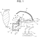
- FIG. 1 is a diagram illustrating a structural example of a vehicle lighting unit according to an embodiment to which the present invention is applied.
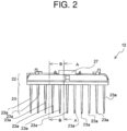
- FIG. 2 is a front view of a heat sink 12 according to the embodiment to which the present invention is applied.
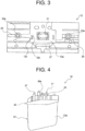
- FIG. 3 is a top view of the heat sink 12 according to the embodiment to which the present invention is applied.
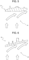
- FIG. 4 is a right side view of the heat sink 12 according to the embodiment to which the present invention is applied.
- FIG. 5 is a sectional view taken along a line A-A in FIG. 2 of the heat sink 12 according to the embodiment to which the present invention is applied.
- FIG. 6 is a sectional view taken along a line B-B in FIG. 2 of the heat sink 12 according to the embodiment to which the present invention is applied.
- FIG. 1 illustrates a simple cross-section of each configuration and a partially omitted lens holder 16 in order to make it easier to understand the configuration of the vehicle lighting unit.
- Vehicle lighting units are used to form headlights for vehicles such as automobiles. Respective headlights are mounted on the left and right sides of a front portion of the vehicle, and the vehicle lighting unit is provided in a lamp chamber formed by a lamp housing having an open front end covered with an outer lens.
- the vehicle lighting unit is provided in the lamp chamber via a vertical optical axis adjustment mechanism and a horizontal optical axis adjustment mechanism, and appropriately illuminates the front of the vehicle.
- the vehicle lighting unit includes a light source 11, a heat sink 12, a reflector 13, a shade unit 14, a projection lens 15, a lens holder 16, and a cooling fan unit 17, and constitutes a projector type headlight unit. A light distribution pattern of the vehicle lighting unit can be switched by using the shade unit 14.
- the light source 11 is configured by mounting a light emitting element 11b, which is a light emitting diode, on a substrate 11a.
- the substrate 11a is disposed on a pedestal portion 21 of an upper surface 12a of the heat sink 12, and a power supply holder is attached from above the substrate, and a terminal of the substrate 11a is connected to a terminal provided on the power supply holder and fixed to the upper surface 12a.
- the heat sink 12 functions as a stand on which the light source 11 is provided. That is, the light emitting element 11b is disposed in the heat sink 12. Therefore, the light source 11 is appropriately lit by supplying electric power from a lighting control circuit to the light emitting element 11b via the power supply holder.
- the heat sink 12 is a heat radiating member that releases heat generated by the light source 11 provided on the upper surface 12a to the outside, includes a base portion 22 and a fin portion 23, and is molded by, for example, die casting.
- the light emitting element 11b is disposed on the pedestal portion 21 of the upper surface 12a of the heat sink 12.
- the power feeding holder (not illustrated) is attached to the light emitting element 11b disposed on the pedestal portion 21 by screws using a screw hole 12b and a screw hole 12c.
- the fin portion 23 is disposed on a back surface of the base portion 22 and radiates heat generated by the light emitting element 11b.
- the heat sink 12 is held by the lamp housing via a bracket (not illustrated) so as to be adjustable up, down, left and right.
- the heat sink 12 includes a first shading piece 27.
- the first shading piece 27 is formed by extending a front end of the upper surface 12a in the width direction while partially protruding.
- the first shading piece 27 is located at the front end of the heat sink 12 to block direct light from the light emitting element 11b.
- the reflector 13 is disposed above the light emitting element 11b, and reflects the emitted light emitted from the light emitting element 11b to the front projection lens 15.
- the reflector 13 is positioned and fixed to the heat sink 12 by being screwed into screw holes 25a provided in the heat transfer ribs 25.
- the front is the same direction as the front of the vehicle. The same applies in the following description.
- the projection lens 15 projects emitted light reflected by the reflector 13 to the front of the vehicle, and forms a light distribution pattern in cooperation with the reflector 13.
- the projection lens 15 is supported by the lens holder 16 and is positioned with respect to the light source 11 and the reflector 13.
- the shade unit 14 switches the light distribution of the projected light projected by the projection lens 15 between a low-beam light distribution pattern and a high-beam light distribution pattern.
- the shade unit 14 includes a bracket plate 31, a shade 32 whose position is displaced due to the switching of light distribution, a solenoid 33 as a driving unit that displaces the position of the shade 32, and a torsional coil spring 54 that transfers the operation of the solenoid 33 to the shade 32.
- the bracket plate 31 rotatably supports a rotating shaft 37.
- the shade 32 blocks a part of the emitted light emitted from the light source 11 to form a cut-off line of the light distribution pattern.
- the shade 32 is configured by attaching a thin plate-shaped first shade portion 42 and a second shade portion 43 to a rotation base 41.
- the rotation base 41 is provided with a bearing piece 44, and the rotating shaft 37 is inserted into the shaft hole.
- the rotation base 41 includes a first positioning piece 46, a second positioning piece 47, and a transfer piece 48.
- the transfer piece 48 is formed by bending a U-shaped cutout at the center in the width direction of the rotation base 41.
- the opening 49 is formed at a position where the transfer piece 48 is present before the U-shaped cutout at the center in the width direction of the rotation base 41 is bent.
- the first shade portion 42 is attached to the upper portion of the rotation base 41.
- the second shade portion 43 is attached to the first shade portion 42 at a regular interval from the first shade portion 42.
- the shade 32 includes a second shading piece 28 formed so as to protrude toward the light source 11 above the opening 49.
- the second shading piece 28 is formed by bending a lower end of the first shade portion 42.
- the second shading piece 28 is located on a path from an upper portion of the reflector 13 to the projection lens 15 through the rotation shaft 37 and the opening 49.
- the solenoid 33 includes a coil 51, a yoke 52 having the the coil 51 built therein, and a plunger 53 that advances and retreats from the yoke 52, and the yoke 52 is fixed to a front surface of the bracket plate 31.
- One end of the torsional coil spring 54 is attached to a tip of the plunger 53.
- the other end of the torsional coil spring 54 is attached to the transfer piece 48. Therefore, the plunger 53 that advances and retreats due to energization and deenergization of the coil 51 displaces the position of the shade 32.
- the cooling fan unit 17 is provided below the heat sink 12, and is configured by rotatably providing a cooling fan inside a rectangular parallelepiped shaped frame.
- the cooling fan unit 17 when the light source 11 emits light, the cooling fan is rotated by driving of the motor, and convection F 1 is generated, so that the lower side of the heat sink 12 is cooled, and failure caused by the heat generated by the light source 11 is prevented.
- a back surface of the base portion 22 is inclined upward from the front to the rear with respect to the pedestal portion 21. That is, the back surface of the base portion 22 has a flat configuration and is provided with an inclination that is oriented upward toward the rear. Therefore, in the heat sink 12, the thickness of the base portion 22 is thicker on the lower side of the light emitting element 11b than on the rear side of the base portion 22.
- the shade 32, the projection lens 15 and the like are attached in front of the heat sink 12.
- the back surface of the base portion 22 is inclined upward from the rear to the front, the convection F1 generated by the cooling fan unit 17 flows into a space that is inside the reflector 13 and where the shade 32 is attached, and therefore the reflector 13 and the shade 32 hinders the convection F1.
- the back surface of the base portion 22 is configured so as to be inclined upward from the front to the rear, so that the convection F1 goes from the lower side of the heat sink 12 toward the reflector 13 along the back surface of the heat sink 12, and further goes along the outside of the reflector 13, and therefore the convection is generated in one direction.
- the heat sink 12 includes the heat transfer ribs 25.
- the heat transfer ribs 25 are disposed on the same surface side as a surface on which the light emitting element 11b is disposed, along the direction from the center of the light emitting element 11b to the outside. That is, the heat transfer ribs 25 are disposed radially from the center of the light emitting element 11b and in a straight line passing through the center of the light emitting element 11b. With such a disposition configuration, the heat transfer ribs 25 efficiently transfer the heat generated by the light emitting element 11b to the outside of the light emitting element 11b.
- the heat transfer ribs 25 are integrally molded by die casting together with the base portion 22 and the fin portion 23.
- the fin portion 23 includes heat radiating fins 23a.
- the heat radiating fins 23a are plate-shaped plate fins disposed at regular intervals along the horizontal direction.
- the back surface of the base portion 22 extends in the front-rear direction on the lower side of the light emitting element 11b, and the tip end side of the heat radiating fins 23a is inclined along the back surface of the base portion 22.
- the back surface side of the base portion 22 and the tip side of the heat radiating fins 23a are substantially parallel to each other. Therefore, while the height limitation of the heat radiating fins 23a by the mold is considered, the heights of the heat radiating fins 23a can be adjusted to the maximum height within a moldable range.
- the inclination angle ⁇ from the horizontal direction upward on the tip side of the heat radiating fins 23a is inclined by 5° or more.
- the inclination angle ⁇ may be 5° to 20°, and 10° to 15° is an optimum range.
- FIG. 7 is a front view of a conventional heat sink 112.
- FIG. 8 is a top view of the conventional heat sink 112.
- FIG. 9 is a right side view of the conventional heat sink 112.
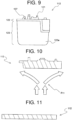
- FIG. 10 is a sectional view taken along a line A-A in FIG. 7 of the conventional heat sink 112.
- FIG. 11 is a cross-sectional view taken along a line B-B in FIG. 7 of the conventional heat sink 112.
- the conventional heat sink 112 includes a base portion 122 and a fin portion 123 including heat radiating fins 123a, and the base portion 122 is also provided with a first light shading piece 127 on an upper surface 112a.
- a pedestal portion 121, a screw hole 112b, a screw hole 112c, and a screw hole 125a are provided on the upper surface 112a.
- an upper surface 112a of the base portion 122 and the back surface side of the base portion 122 are horizontally configured. Therefore, when the pedestal portion 121 is provided, the size becomes larger as a whole, and therefore the thickness of the base portion 122 becomes thicker as a whole. Therefore, since the weight of the heat sink 112 becomes large, it is not possible to reduce the weight.
- convection F11 is generated from below the base portion 122, the convection F11 is generated separately in the front direction and the rear direction of the base portion 122, and therefore a part of the convection F11 flows into a space that is inside a reflector 13 and where the shade 32 is attached. As a result, the convection F11 tends to be stagnant, and the heat radiation performance deteriorates.
- the back surface of the base portion 22 is inclined with respect to the pedestal portion 21. Therefore, since the thickness of the base portion 22 is reduced by the amount of the inclination, it is possible to realize the weight reduction.
- the direction of the convection F1 is the direction in which the convection flows upward from the front to the rear due to an updraft of the heat generated by the light emitting element 11b and the inclination of the back surface of the base portion 22. Therefore, the convection F1 is not drawn into the space inside the reflector 13 from the front of the base portion 22 via the upper side of the light emitting element 11b, and therefore the convection F1 is not hindered by the reflector 13 or the like. From the above description, the vehicle lighting unit can realize weight reduction and improve heat radiation performance.
- the thickness of the base portion 22 is thicker on the lower side of the light emitting element 11b than on the rear side of the base portion 22. Accordingly, the heat capacity on the lower side of the light emitting element 11b that is the heat source is large, and therefore the temperature rise rate around the light emitting element 11b can be delayed. Therefore, it is possible to suppress change in the characteristics due to the heat of the light emitting element 11b.
- the heat transfer ribs 25 are disposed on the same surface side as the surface on which the light emitting element 11b is disposed, along the direction from the center of the light emitting element 11b to the outside, and the heat generated by the light emitting element 11b is transferred. Accordingly, radiant heat generated by the light emitting element 11b can be efficiently transferred as conductive heat to the outside of the light emitting element 11b. Therefore, since the temperature around the light emitting element 11b can be efficiently transferred to the heat sink 12, it is possible to suppress the temperature rise of the light emitting element 11b, and it is possible to prevent the characteristic change such as the decrease in the luminous efficiency due to the heat of the light emitting element 11b.
- the tip end side of the heat radiating fins 23a is inclined along the back surface of the base portion 22. Accordingly, the height of each heat radiating fin 23a can be maximized while the height limitation of the heat radiating fin 23a by the mold is considered. Therefore, the heat radiation areas of the heat radiating fins 23a can be increased to the maximum within the moldable range, and therefore it is possible to promote a heat radiation effect.
- the heat radiating fins 23a are each composed of a plate-shaped plate fin, but the present disclosure is not particularly limited to this.
- the heat radiating fin 23a may be composed of a collage fin.
- cooling fan unit 17 is provided and the convection F1 is generated by forced convection using the air volume supplied from the cooling fan unit 17 is described, but the present disclosure is not particularly limited to this.
- convection F1 may be generated by natural convection.
- the back surface of the base portion 22 has a flat configuration and an inclination is provided is described, but the present disclosure is not particularly limited to this.
- the back surface of the base portion 22 may be curved and be provided with an inclination. That is, the back surface of the base portion 22 only needs to be inclined upward from the front to the rear as a whole, and a part thereof may have a different shape.
Landscapes
- Engineering & Computer Science (AREA)
- General Engineering & Computer Science (AREA)
- Physics & Mathematics (AREA)
- Microelectronics & Electronic Packaging (AREA)
- Optics & Photonics (AREA)
- Non-Portable Lighting Devices Or Systems Thereof (AREA)
- Arrangement Of Elements, Cooling, Sealing, Or The Like Of Lighting Devices (AREA)
Claims (4)
- Bloc d'éclairage de véhicule comprenant :un dissipateur thermique (12) ;un élément émetteur de lumière (11b) disposé dans le dissipateur thermique (12) ; etun réflecteur (13) qui est disposé au-dessus de l'élément émetteur de lumière (11b), et qui réfléchit la lumière émise à l'avant de l'élément émetteur de lumière (11b), vers une lentille de projection (15),dans lequel le dissipateur thermique (12) comprend :une partie de base (22) pour disposer l'élément émetteur de lumière (11b) sur une partie de support (21) sur une surface supérieure (12a) du dissipateur thermique (12) ; etune partie d'ailettes (23) qui est disposée sur une surface de dos de la partie de base (22), et qui rayonne la chaleur générée par l'élément émetteur de lumière (11b),dans lequel la surface de dos de la partie de base (22) est inclinée par rapport à la partie de support (21) ;caractérisé en ce quele dissipateur thermique (12) comprend en outre des nervures de transfert de chaleur (25) qui sont disposées sur un même côté de surface qu'une surface sur laquelle l'élément émetteur de lumière (11b) est disposé, en dessous du réflecteur (13), le long d'une direction allant d'un centre de l'élément émetteur de lumière (1 1b) jusqu'à l'extérieur, pour transférer la chaleur générée par l'élément émetteur de lumière (11b).
- Bloc d'éclairage de véhicule selon la revendication 1, dans lequel
dans le dissipateur thermique (12), une épaisseur de la partie de base (22) est plus épaisse sur un côté inférieur de l'élément émetteur de lumière (11b) que sur un côté arrière de la partie de base, où un côté avant de la partie de base (22) du dissipateur thermique (12) est dans une direction avant vers la lentille de projection (15) et le côté arrière de la partie de base (22) est orienté à l'opposé de la direction avant. - Bloc d'éclairage de véhicule selon la revendication 1, où
le réflecteur 13 est positionné et fixé au dissipateur thermique (12) en étant vissé dans des trous de vis (25a) fournis dans les nervures de transfert de chaleur (25). - Bloc d'éclairage de véhicule selon la revendication 1, dans lequel
la partie d'ailettes (23) comprend des ailettes rayonnant la chaleur (23a) composées d'ailettes à plaques en forme de plaques disposées à un intervalle régulier le long d'une direction horizontale, et dans le dissipateur thermique (12), la surface de dos de la partie de base (22) s'étend dans une direction d'avant en arrière sur le côté inférieur de l'élément émetteur de lumière (1 1b), la direction d'avant en arrière étant une direction opposée à la lentille de projection (15), et un côté d'extrémité de pointe des ailettes rayonnant la chaleur (23a) est incliné le long de la surface de dos de la partie de base (22).
Applications Claiming Priority (2)
| Application Number | Priority Date | Filing Date | Title |
|---|---|---|---|
| JP2018145559A JP2020021665A (ja) | 2018-08-02 | 2018-08-02 | 車両用灯具 |
| PCT/JP2019/029827 WO2020027128A1 (fr) | 2018-08-02 | 2019-07-30 | Bloc d'éclairage de véhicule |
Publications (3)
| Publication Number | Publication Date |
|---|---|
| EP3832196A1 EP3832196A1 (fr) | 2021-06-09 |
| EP3832196A4 EP3832196A4 (fr) | 2021-12-22 |
| EP3832196B1 true EP3832196B1 (fr) | 2023-06-14 |
Family
ID=69232630
Family Applications (1)
| Application Number | Title | Priority Date | Filing Date |
|---|---|---|---|
| EP19844537.1A Active EP3832196B1 (fr) | 2018-08-02 | 2019-07-30 | Bloc d'éclairage de véhicule |
Country Status (5)
| Country | Link |
|---|---|
| US (1) | US11300267B2 (fr) |
| EP (1) | EP3832196B1 (fr) |
| JP (1) | JP2020021665A (fr) |
| CN (1) | CN112424528B (fr) |
| WO (1) | WO2020027128A1 (fr) |
Families Citing this family (2)
| Publication number | Priority date | Publication date | Assignee | Title |
|---|---|---|---|---|
| WO2023063147A1 (fr) * | 2021-10-15 | 2023-04-20 | 株式会社小糸製作所 | Lampe de véhicule |
| US11639781B1 (en) | 2022-02-11 | 2023-05-02 | Toyota Motor Engineering & Manufacturing North America, Inc. | Vehicle trailer hitch illumination system |
Family Cites Families (19)
| Publication number | Priority date | Publication date | Assignee | Title |
|---|---|---|---|---|
| JP4771723B2 (ja) * | 2005-03-24 | 2011-09-14 | 市光工業株式会社 | 車両用灯具 |
| DE102007016442B4 (de) * | 2007-04-05 | 2017-02-16 | Volkswagen Ag | LED-Leuchte für ein Kraftfahrzeug |
| JP4863502B2 (ja) | 2007-05-21 | 2012-01-25 | スタンレー電気株式会社 | 車両前照灯 |
| JP5008506B2 (ja) * | 2007-09-14 | 2012-08-22 | スタンレー電気株式会社 | Ledランプユニット |
| JP2013089425A (ja) * | 2011-10-17 | 2013-05-13 | Osram Gmbh | ヘッドランプ用led光源モジュール |
| JP5912539B2 (ja) * | 2012-01-10 | 2016-04-27 | 株式会社小糸製作所 | 車両用前照灯 |
| JP2014103058A (ja) * | 2012-11-22 | 2014-06-05 | Stanley Electric Co Ltd | Ledランプ |
| US9528677B2 (en) * | 2013-01-28 | 2016-12-27 | Koito Manufacturing Co., Ltd. | Vehicle lamp unit and vehicle headlamp |
| JP2015035349A (ja) * | 2013-08-09 | 2015-02-19 | パナソニック株式会社 | 車両用ヘッドランプ装置 |
| JP6252110B2 (ja) * | 2013-11-05 | 2017-12-27 | 市光工業株式会社 | 車両用灯具 |
| JP6299353B2 (ja) * | 2014-04-08 | 2018-03-28 | 市光工業株式会社 | 車両用灯具 |
| JP2016072166A (ja) * | 2014-10-01 | 2016-05-09 | パナソニックIpマネジメント株式会社 | 照明装置と、それを搭載した自動車 |
| JP6511870B2 (ja) * | 2015-03-05 | 2019-05-15 | 市光工業株式会社 | 車両用灯具 |
| JP6538394B2 (ja) | 2015-03-25 | 2019-07-03 | 株式会社ソノコム | ダミーパターンを使用したサスペンドメタルマスクおよびダミーパターンを使用したサスペンドメタルマスクの製造方法 |
| JP2016197511A (ja) * | 2015-04-02 | 2016-11-24 | 市光工業株式会社 | 車両用灯具 |
| JP6770347B2 (ja) * | 2016-06-27 | 2020-10-14 | 株式会社小糸製作所 | 車両用前照灯 |
| JP6674851B2 (ja) * | 2016-06-30 | 2020-04-01 | スタンレー電気株式会社 | 車両用灯具 |
| JP2018037205A (ja) * | 2016-08-30 | 2018-03-08 | スタンレー電気株式会社 | 車両用灯具 |
| JP6825308B2 (ja) * | 2016-11-04 | 2021-02-03 | 市光工業株式会社 | 車両用灯具 |
-
2018
- 2018-08-02 JP JP2018145559A patent/JP2020021665A/ja active Pending
-
2019
- 2019-07-30 EP EP19844537.1A patent/EP3832196B1/fr active Active
- 2019-07-30 WO PCT/JP2019/029827 patent/WO2020027128A1/fr not_active Ceased
- 2019-07-30 CN CN201980047271.3A patent/CN112424528B/zh active Active
- 2019-07-30 US US17/265,034 patent/US11300267B2/en active Active
Also Published As
| Publication number | Publication date |
|---|---|
| WO2020027128A1 (fr) | 2020-02-06 |
| EP3832196A4 (fr) | 2021-12-22 |
| JP2020021665A (ja) | 2020-02-06 |
| US20210302004A1 (en) | 2021-09-30 |
| CN112424528A (zh) | 2021-02-26 |
| EP3832196A1 (fr) | 2021-06-09 |
| CN112424528B (zh) | 2023-08-01 |
| US11300267B2 (en) | 2022-04-12 |
Similar Documents
| Publication | Publication Date | Title |
|---|---|---|
| JP5457061B2 (ja) | 車両用前照灯 | |
| JP5275672B2 (ja) | 車両用灯具 | |
| CN101806419B (zh) | 车辆用灯具 | |
| EP2484556B1 (fr) | Phare de véhicule | |
| EP2522898B1 (fr) | Lampe de véhicule | |
| JP6034611B2 (ja) | プロジェクタ型車両用前照灯 | |
| EP2148133A2 (fr) | Lampe d'automobile dotée d'un ventilateur | |
| JP5806053B2 (ja) | 車両用前照灯 | |
| EP3705777B1 (fr) | Lampe de véhicule | |
| JP7601878B2 (ja) | 車輌用灯具 | |
| JP6515700B2 (ja) | プロジェクタ型車両用前照灯 | |
| EP3832196B1 (fr) | Bloc d'éclairage de véhicule | |
| JP5658016B2 (ja) | 車両用灯具 | |
| US9227554B2 (en) | Vehicular lamp | |
| JP2018005980A (ja) | 車両用前照灯および光源ユニット | |
| JP2014165150A (ja) | 車両用灯具 | |
| JP2016173942A (ja) | 車両用前照灯 | |
| JP5491828B2 (ja) | 車両用灯具 | |
| JP2010165537A (ja) | 車両用灯具 | |
| JP6195515B2 (ja) | 車輌用前照灯 | |
| CN222963789U (zh) | 双光透镜汽车大灯 | |
| CN213420969U (zh) | 一种新型led透镜大灯 | |
| CN221631813U (zh) | 一种方便组装的摄影灯 | |
| CN218763084U (zh) | 一种照明灯具 | |
| CN214664190U (zh) | 一种可快速散热的汽车激光透镜 |
Legal Events
| Date | Code | Title | Description |
|---|---|---|---|
| STAA | Information on the status of an ep patent application or granted ep patent |
Free format text: STATUS: THE INTERNATIONAL PUBLICATION HAS BEEN MADE |
|
| PUAI | Public reference made under article 153(3) epc to a published international application that has entered the european phase |
Free format text: ORIGINAL CODE: 0009012 |
|
| STAA | Information on the status of an ep patent application or granted ep patent |
Free format text: STATUS: REQUEST FOR EXAMINATION WAS MADE |
|
| 17P | Request for examination filed |
Effective date: 20210202 |
|
| AK | Designated contracting states |
Kind code of ref document: A1 Designated state(s): AL AT BE BG CH CY CZ DE DK EE ES FI FR GB GR HR HU IE IS IT LI LT LU LV MC MK MT NL NO PL PT RO RS SE SI SK SM TR |
|
| DAV | Request for validation of the european patent (deleted) | ||
| DAX | Request for extension of the european patent (deleted) | ||
| A4 | Supplementary search report drawn up and despatched |
Effective date: 20211119 |
|
| RIC1 | Information provided on ipc code assigned before grant |
Ipc: F21S 45/47 20180101ALI20211115BHEP Ipc: F21S 45/435 20180101ALI20211115BHEP Ipc: F21S 41/19 20180101ALI20211115BHEP Ipc: F21Y 115/10 20160101ALI20211115BHEP Ipc: F21W 102/13 20180101ALI20211115BHEP Ipc: F21V 29/76 20150101ALI20211115BHEP Ipc: F21V 29/67 20150101ALI20211115BHEP Ipc: F21V 29/503 20150101ALI20211115BHEP Ipc: F21S 45/49 20180101ALI20211115BHEP Ipc: F21S 45/48 20180101ALI20211115BHEP Ipc: F21S 41/148 20180101ALI20211115BHEP Ipc: F21S 45/43 20180101AFI20211115BHEP |
|
| GRAP | Despatch of communication of intention to grant a patent |
Free format text: ORIGINAL CODE: EPIDOSNIGR1 |
|
| STAA | Information on the status of an ep patent application or granted ep patent |
Free format text: STATUS: GRANT OF PATENT IS INTENDED |
|
| RIC1 | Information provided on ipc code assigned before grant |
Ipc: F21S 45/47 20180101ALI20221216BHEP Ipc: F21S 45/435 20180101ALI20221216BHEP Ipc: F21S 41/19 20180101ALI20221216BHEP Ipc: F21Y 115/10 20160101ALI20221216BHEP Ipc: F21W 102/13 20180101ALI20221216BHEP Ipc: F21V 29/76 20150101ALI20221216BHEP Ipc: F21V 29/67 20150101ALI20221216BHEP Ipc: F21V 29/503 20150101ALI20221216BHEP Ipc: F21S 45/49 20180101ALI20221216BHEP Ipc: F21S 45/48 20180101ALI20221216BHEP Ipc: F21S 41/148 20180101ALI20221216BHEP Ipc: F21S 45/43 20180101AFI20221216BHEP |
|
| INTG | Intention to grant announced |
Effective date: 20230124 |
|
| GRAS | Grant fee paid |
Free format text: ORIGINAL CODE: EPIDOSNIGR3 |
|
| GRAA | (expected) grant |
Free format text: ORIGINAL CODE: 0009210 |
|
| STAA | Information on the status of an ep patent application or granted ep patent |
Free format text: STATUS: THE PATENT HAS BEEN GRANTED |
|
| AK | Designated contracting states |
Kind code of ref document: B1 Designated state(s): AL AT BE BG CH CY CZ DE DK EE ES FI FR GB GR HR HU IE IS IT LI LT LU LV MC MK MT NL NO PL PT RO RS SE SI SK SM TR |
|
| REG | Reference to a national code |
Ref country code: CH Ref legal event code: EP |
|
| REG | Reference to a national code |
Ref country code: DE Ref legal event code: R096 Ref document number: 602019031164 Country of ref document: DE |
|
| REG | Reference to a national code |
Ref country code: AT Ref legal event code: REF Ref document number: 1579459 Country of ref document: AT Kind code of ref document: T Effective date: 20230715 |
|
| REG | Reference to a national code |
Ref country code: LT Ref legal event code: MG9D |
|
| REG | Reference to a national code |
Ref country code: NL Ref legal event code: MP Effective date: 20230614 |
|
| PG25 | Lapsed in a contracting state [announced via postgrant information from national office to epo] |
Ref country code: SE Free format text: LAPSE BECAUSE OF FAILURE TO SUBMIT A TRANSLATION OF THE DESCRIPTION OR TO PAY THE FEE WITHIN THE PRESCRIBED TIME-LIMIT Effective date: 20230614 Ref country code: NO Free format text: LAPSE BECAUSE OF FAILURE TO SUBMIT A TRANSLATION OF THE DESCRIPTION OR TO PAY THE FEE WITHIN THE PRESCRIBED TIME-LIMIT Effective date: 20230914 Ref country code: ES Free format text: LAPSE BECAUSE OF FAILURE TO SUBMIT A TRANSLATION OF THE DESCRIPTION OR TO PAY THE FEE WITHIN THE PRESCRIBED TIME-LIMIT Effective date: 20230614 |
|
| REG | Reference to a national code |
Ref country code: AT Ref legal event code: MK05 Ref document number: 1579459 Country of ref document: AT Kind code of ref document: T Effective date: 20230614 |
|
| PG25 | Lapsed in a contracting state [announced via postgrant information from national office to epo] |
Ref country code: RS Free format text: LAPSE BECAUSE OF FAILURE TO SUBMIT A TRANSLATION OF THE DESCRIPTION OR TO PAY THE FEE WITHIN THE PRESCRIBED TIME-LIMIT Effective date: 20230614 Ref country code: NL Free format text: LAPSE BECAUSE OF FAILURE TO SUBMIT A TRANSLATION OF THE DESCRIPTION OR TO PAY THE FEE WITHIN THE PRESCRIBED TIME-LIMIT Effective date: 20230614 Ref country code: LV Free format text: LAPSE BECAUSE OF FAILURE TO SUBMIT A TRANSLATION OF THE DESCRIPTION OR TO PAY THE FEE WITHIN THE PRESCRIBED TIME-LIMIT Effective date: 20230614 Ref country code: LT Free format text: LAPSE BECAUSE OF FAILURE TO SUBMIT A TRANSLATION OF THE DESCRIPTION OR TO PAY THE FEE WITHIN THE PRESCRIBED TIME-LIMIT Effective date: 20230614 Ref country code: HR Free format text: LAPSE BECAUSE OF FAILURE TO SUBMIT A TRANSLATION OF THE DESCRIPTION OR TO PAY THE FEE WITHIN THE PRESCRIBED TIME-LIMIT Effective date: 20230614 Ref country code: GR Free format text: LAPSE BECAUSE OF FAILURE TO SUBMIT A TRANSLATION OF THE DESCRIPTION OR TO PAY THE FEE WITHIN THE PRESCRIBED TIME-LIMIT Effective date: 20230915 |
|
| PG25 | Lapsed in a contracting state [announced via postgrant information from national office to epo] |
Ref country code: FI Free format text: LAPSE BECAUSE OF FAILURE TO SUBMIT A TRANSLATION OF THE DESCRIPTION OR TO PAY THE FEE WITHIN THE PRESCRIBED TIME-LIMIT Effective date: 20230614 |
|
| PG25 | Lapsed in a contracting state [announced via postgrant information from national office to epo] |
Ref country code: SK Free format text: LAPSE BECAUSE OF FAILURE TO SUBMIT A TRANSLATION OF THE DESCRIPTION OR TO PAY THE FEE WITHIN THE PRESCRIBED TIME-LIMIT Effective date: 20230614 |
|
| PG25 | Lapsed in a contracting state [announced via postgrant information from national office to epo] |
Ref country code: IS Free format text: LAPSE BECAUSE OF FAILURE TO SUBMIT A TRANSLATION OF THE DESCRIPTION OR TO PAY THE FEE WITHIN THE PRESCRIBED TIME-LIMIT Effective date: 20231014 |
|
| PG25 | Lapsed in a contracting state [announced via postgrant information from national office to epo] |
Ref country code: SM Free format text: LAPSE BECAUSE OF FAILURE TO SUBMIT A TRANSLATION OF THE DESCRIPTION OR TO PAY THE FEE WITHIN THE PRESCRIBED TIME-LIMIT Effective date: 20230614 Ref country code: SK Free format text: LAPSE BECAUSE OF FAILURE TO SUBMIT A TRANSLATION OF THE DESCRIPTION OR TO PAY THE FEE WITHIN THE PRESCRIBED TIME-LIMIT Effective date: 20230614 Ref country code: RO Free format text: LAPSE BECAUSE OF FAILURE TO SUBMIT A TRANSLATION OF THE DESCRIPTION OR TO PAY THE FEE WITHIN THE PRESCRIBED TIME-LIMIT Effective date: 20230614 Ref country code: PT Free format text: LAPSE BECAUSE OF FAILURE TO SUBMIT A TRANSLATION OF THE DESCRIPTION OR TO PAY THE FEE WITHIN THE PRESCRIBED TIME-LIMIT Effective date: 20231016 Ref country code: IS Free format text: LAPSE BECAUSE OF FAILURE TO SUBMIT A TRANSLATION OF THE DESCRIPTION OR TO PAY THE FEE WITHIN THE PRESCRIBED TIME-LIMIT Effective date: 20231014 Ref country code: EE Free format text: LAPSE BECAUSE OF FAILURE TO SUBMIT A TRANSLATION OF THE DESCRIPTION OR TO PAY THE FEE WITHIN THE PRESCRIBED TIME-LIMIT Effective date: 20230614 Ref country code: CZ Free format text: LAPSE BECAUSE OF FAILURE TO SUBMIT A TRANSLATION OF THE DESCRIPTION OR TO PAY THE FEE WITHIN THE PRESCRIBED TIME-LIMIT Effective date: 20230614 Ref country code: AT Free format text: LAPSE BECAUSE OF FAILURE TO SUBMIT A TRANSLATION OF THE DESCRIPTION OR TO PAY THE FEE WITHIN THE PRESCRIBED TIME-LIMIT Effective date: 20230614 |
|
| PG25 | Lapsed in a contracting state [announced via postgrant information from national office to epo] |
Ref country code: PL Free format text: LAPSE BECAUSE OF FAILURE TO SUBMIT A TRANSLATION OF THE DESCRIPTION OR TO PAY THE FEE WITHIN THE PRESCRIBED TIME-LIMIT Effective date: 20230614 |
|
| REG | Reference to a national code |
Ref country code: CH Ref legal event code: PL |
|
| PG25 | Lapsed in a contracting state [announced via postgrant information from national office to epo] |
Ref country code: MC Free format text: LAPSE BECAUSE OF FAILURE TO SUBMIT A TRANSLATION OF THE DESCRIPTION OR TO PAY THE FEE WITHIN THE PRESCRIBED TIME-LIMIT Effective date: 20230614 |
|
| REG | Reference to a national code |
Ref country code: DE Ref legal event code: R097 Ref document number: 602019031164 Country of ref document: DE |
|
| REG | Reference to a national code |
Ref country code: BE Ref legal event code: MM Effective date: 20230731 |
|
| PG25 | Lapsed in a contracting state [announced via postgrant information from national office to epo] |
Ref country code: LU Free format text: LAPSE BECAUSE OF NON-PAYMENT OF DUE FEES Effective date: 20230730 |
|
| PG25 | Lapsed in a contracting state [announced via postgrant information from national office to epo] |
Ref country code: MC Free format text: LAPSE BECAUSE OF FAILURE TO SUBMIT A TRANSLATION OF THE DESCRIPTION OR TO PAY THE FEE WITHIN THE PRESCRIBED TIME-LIMIT Effective date: 20230614 Ref country code: LU Free format text: LAPSE BECAUSE OF NON-PAYMENT OF DUE FEES Effective date: 20230730 |
|
| PLBE | No opposition filed within time limit |
Free format text: ORIGINAL CODE: 0009261 |
|
| STAA | Information on the status of an ep patent application or granted ep patent |
Free format text: STATUS: NO OPPOSITION FILED WITHIN TIME LIMIT |
|
| REG | Reference to a national code |
Ref country code: IE Ref legal event code: MM4A |
|
| PG25 | Lapsed in a contracting state [announced via postgrant information from national office to epo] |
Ref country code: DK Free format text: LAPSE BECAUSE OF FAILURE TO SUBMIT A TRANSLATION OF THE DESCRIPTION OR TO PAY THE FEE WITHIN THE PRESCRIBED TIME-LIMIT Effective date: 20230614 Ref country code: CH Free format text: LAPSE BECAUSE OF NON-PAYMENT OF DUE FEES Effective date: 20230731 |
|
| PG25 | Lapsed in a contracting state [announced via postgrant information from national office to epo] |
Ref country code: SI Free format text: LAPSE BECAUSE OF FAILURE TO SUBMIT A TRANSLATION OF THE DESCRIPTION OR TO PAY THE FEE WITHIN THE PRESCRIBED TIME-LIMIT Effective date: 20230614 |
|
| 26N | No opposition filed |
Effective date: 20240315 |
|
| PG25 | Lapsed in a contracting state [announced via postgrant information from national office to epo] |
Ref country code: SI Free format text: LAPSE BECAUSE OF FAILURE TO SUBMIT A TRANSLATION OF THE DESCRIPTION OR TO PAY THE FEE WITHIN THE PRESCRIBED TIME-LIMIT Effective date: 20230614 Ref country code: IT Free format text: LAPSE BECAUSE OF FAILURE TO SUBMIT A TRANSLATION OF THE DESCRIPTION OR TO PAY THE FEE WITHIN THE PRESCRIBED TIME-LIMIT Effective date: 20230614 Ref country code: BE Free format text: LAPSE BECAUSE OF NON-PAYMENT OF DUE FEES Effective date: 20230731 |
|
| PG25 | Lapsed in a contracting state [announced via postgrant information from national office to epo] |
Ref country code: IE Free format text: LAPSE BECAUSE OF NON-PAYMENT OF DUE FEES Effective date: 20230730 |
|
| PG25 | Lapsed in a contracting state [announced via postgrant information from national office to epo] |
Ref country code: IE Free format text: LAPSE BECAUSE OF NON-PAYMENT OF DUE FEES Effective date: 20230730 |
|
| PG25 | Lapsed in a contracting state [announced via postgrant information from national office to epo] |
Ref country code: BG Free format text: LAPSE BECAUSE OF FAILURE TO SUBMIT A TRANSLATION OF THE DESCRIPTION OR TO PAY THE FEE WITHIN THE PRESCRIBED TIME-LIMIT Effective date: 20230614 |
|
| PG25 | Lapsed in a contracting state [announced via postgrant information from national office to epo] |
Ref country code: BG Free format text: LAPSE BECAUSE OF FAILURE TO SUBMIT A TRANSLATION OF THE DESCRIPTION OR TO PAY THE FEE WITHIN THE PRESCRIBED TIME-LIMIT Effective date: 20230614 |
|
| PG25 | Lapsed in a contracting state [announced via postgrant information from national office to epo] |
Ref country code: CY Free format text: LAPSE BECAUSE OF FAILURE TO SUBMIT A TRANSLATION OF THE DESCRIPTION OR TO PAY THE FEE WITHIN THE PRESCRIBED TIME-LIMIT; INVALID AB INITIO Effective date: 20190730 |
|
| PG25 | Lapsed in a contracting state [announced via postgrant information from national office to epo] |
Ref country code: HU Free format text: LAPSE BECAUSE OF FAILURE TO SUBMIT A TRANSLATION OF THE DESCRIPTION OR TO PAY THE FEE WITHIN THE PRESCRIBED TIME-LIMIT; INVALID AB INITIO Effective date: 20190730 |
|
| PGFP | Annual fee paid to national office [announced via postgrant information from national office to epo] |
Ref country code: DE Payment date: 20250722 Year of fee payment: 7 |
|
| PGFP | Annual fee paid to national office [announced via postgrant information from national office to epo] |
Ref country code: GB Payment date: 20250722 Year of fee payment: 7 |
|
| PGFP | Annual fee paid to national office [announced via postgrant information from national office to epo] |
Ref country code: FR Payment date: 20250725 Year of fee payment: 7 |
|
| PG25 | Lapsed in a contracting state [announced via postgrant information from national office to epo] |
Ref country code: TR Free format text: LAPSE BECAUSE OF FAILURE TO SUBMIT A TRANSLATION OF THE DESCRIPTION OR TO PAY THE FEE WITHIN THE PRESCRIBED TIME-LIMIT Effective date: 20230614 |