EP3832242B1 - Kondensator - Google Patents
Kondensator Download PDFInfo
- Publication number
- EP3832242B1 EP3832242B1 EP19840963.3A EP19840963A EP3832242B1 EP 3832242 B1 EP3832242 B1 EP 3832242B1 EP 19840963 A EP19840963 A EP 19840963A EP 3832242 B1 EP3832242 B1 EP 3832242B1
- Authority
- EP
- European Patent Office
- Prior art keywords
- outlet
- condenser
- inlet pipe
- impact plate
- inlet
- Prior art date
- Legal status (The legal status is an assumption and is not a legal conclusion. Google has not performed a legal analysis and makes no representation as to the accuracy of the status listed.)
- Active
Links
Images




Classifications
-
- F—MECHANICAL ENGINEERING; LIGHTING; HEATING; WEAPONS; BLASTING
- F28—HEAT EXCHANGE IN GENERAL
- F28D—HEAT-EXCHANGE APPARATUS, NOT PROVIDED FOR IN ANOTHER SUBCLASS, IN WHICH THE HEAT-EXCHANGE MEDIA DO NOT COME INTO DIRECT CONTACT
- F28D7/00—Heat-exchange apparatus having stationary tubular conduit assemblies for both heat-exchange media, the media being in contact with different sides of a conduit wall
- F28D7/16—Heat-exchange apparatus having stationary tubular conduit assemblies for both heat-exchange media, the media being in contact with different sides of a conduit wall the conduits being arranged in parallel spaced relation
- F28D7/1607—Heat-exchange apparatus having stationary tubular conduit assemblies for both heat-exchange media, the media being in contact with different sides of a conduit wall the conduits being arranged in parallel spaced relation with particular pattern of flow of the heat exchange media, e.g. change of flow direction
-
- F—MECHANICAL ENGINEERING; LIGHTING; HEATING; WEAPONS; BLASTING
- F25—REFRIGERATION OR COOLING; COMBINED HEATING AND REFRIGERATION SYSTEMS; HEAT PUMP SYSTEMS; MANUFACTURE OR STORAGE OF ICE; LIQUEFACTION SOLIDIFICATION OF GASES
- F25B—REFRIGERATION MACHINES, PLANTS OR SYSTEMS; COMBINED HEATING AND REFRIGERATION SYSTEMS; HEAT PUMP SYSTEMS
- F25B39/00—Evaporators; Condensers
- F25B39/04—Condensers
-
- F—MECHANICAL ENGINEERING; LIGHTING; HEATING; WEAPONS; BLASTING
- F28—HEAT EXCHANGE IN GENERAL
- F28B—STEAM OR VAPOUR CONDENSERS
- F28B1/00—Condensers in which the steam or vapour is separate from the cooling medium by walls, e.g. surface condenser
- F28B1/02—Condensers in which the steam or vapour is separate from the cooling medium by walls, e.g. surface condenser using water or other liquid as the cooling medium
-
- F—MECHANICAL ENGINEERING; LIGHTING; HEATING; WEAPONS; BLASTING
- F28—HEAT EXCHANGE IN GENERAL
- F28D—HEAT-EXCHANGE APPARATUS, NOT PROVIDED FOR IN ANOTHER SUBCLASS, IN WHICH THE HEAT-EXCHANGE MEDIA DO NOT COME INTO DIRECT CONTACT
- F28D7/00—Heat-exchange apparatus having stationary tubular conduit assemblies for both heat-exchange media, the media being in contact with different sides of a conduit wall
- F28D7/10—Heat-exchange apparatus having stationary tubular conduit assemblies for both heat-exchange media, the media being in contact with different sides of a conduit wall the conduits being arranged one within the other, e.g. concentrically
- F28D7/12—Heat-exchange apparatus having stationary tubular conduit assemblies for both heat-exchange media, the media being in contact with different sides of a conduit wall the conduits being arranged one within the other, e.g. concentrically the surrounding tube being closed at one end, e.g. return type
-
- F—MECHANICAL ENGINEERING; LIGHTING; HEATING; WEAPONS; BLASTING
- F28—HEAT EXCHANGE IN GENERAL
- F28D—HEAT-EXCHANGE APPARATUS, NOT PROVIDED FOR IN ANOTHER SUBCLASS, IN WHICH THE HEAT-EXCHANGE MEDIA DO NOT COME INTO DIRECT CONTACT
- F28D7/00—Heat-exchange apparatus having stationary tubular conduit assemblies for both heat-exchange media, the media being in contact with different sides of a conduit wall
- F28D7/16—Heat-exchange apparatus having stationary tubular conduit assemblies for both heat-exchange media, the media being in contact with different sides of a conduit wall the conduits being arranged in parallel spaced relation
- F28D7/163—Heat-exchange apparatus having stationary tubular conduit assemblies for both heat-exchange media, the media being in contact with different sides of a conduit wall the conduits being arranged in parallel spaced relation with conduit assemblies having a particular shape, e.g. square or annular; with assemblies of conduits having different geometrical features; with multiple groups of conduits connected in series or parallel and arranged inside common casing
- F28D7/1638—Heat-exchange apparatus having stationary tubular conduit assemblies for both heat-exchange media, the media being in contact with different sides of a conduit wall the conduits being arranged in parallel spaced relation with conduit assemblies having a particular shape, e.g. square or annular; with assemblies of conduits having different geometrical features; with multiple groups of conduits connected in series or parallel and arranged inside common casing with particular pattern of flow or the heat exchange medium flowing inside the conduits assemblies, e.g. change of flow direction from one conduit assembly to another one
-
- F—MECHANICAL ENGINEERING; LIGHTING; HEATING; WEAPONS; BLASTING
- F28—HEAT EXCHANGE IN GENERAL
- F28F—DETAILS OF HEAT-EXCHANGE AND HEAT-TRANSFER APPARATUS, OF GENERAL APPLICATION
- F28F9/00—Casings; Header boxes; Auxiliary supports for elements; Auxiliary members within casings
- F28F9/005—Other auxiliary members within casings, e.g. internal filling means or sealing means
-
- F—MECHANICAL ENGINEERING; LIGHTING; HEATING; WEAPONS; BLASTING
- F28—HEAT EXCHANGE IN GENERAL
- F28F—DETAILS OF HEAT-EXCHANGE AND HEAT-TRANSFER APPARATUS, OF GENERAL APPLICATION
- F28F9/00—Casings; Header boxes; Auxiliary supports for elements; Auxiliary members within casings
- F28F9/02—Header boxes; End plates
- F28F9/026—Header boxes; End plates with static flow control means, e.g. with means for uniformly distributing heat exchange media into conduits
- F28F9/0263—Header boxes; End plates with static flow control means, e.g. with means for uniformly distributing heat exchange media into conduits by varying the geometry or cross-section of header box
-
- F—MECHANICAL ENGINEERING; LIGHTING; HEATING; WEAPONS; BLASTING
- F28—HEAT EXCHANGE IN GENERAL
- F28F—DETAILS OF HEAT-EXCHANGE AND HEAT-TRANSFER APPARATUS, OF GENERAL APPLICATION
- F28F9/00—Casings; Header boxes; Auxiliary supports for elements; Auxiliary members within casings
- F28F9/02—Header boxes; End plates
- F28F9/026—Header boxes; End plates with static flow control means, e.g. with means for uniformly distributing heat exchange media into conduits
- F28F9/0265—Header boxes; End plates with static flow control means, e.g. with means for uniformly distributing heat exchange media into conduits by using guiding means or impingement means inside the header box
-
- F—MECHANICAL ENGINEERING; LIGHTING; HEATING; WEAPONS; BLASTING
- F25—REFRIGERATION OR COOLING; COMBINED HEATING AND REFRIGERATION SYSTEMS; HEAT PUMP SYSTEMS; MANUFACTURE OR STORAGE OF ICE; LIQUEFACTION SOLIDIFICATION OF GASES
- F25B—REFRIGERATION MACHINES, PLANTS OR SYSTEMS; COMBINED HEATING AND REFRIGERATION SYSTEMS; HEAT PUMP SYSTEMS
- F25B2339/00—Details of evaporators; Details of condensers
- F25B2339/04—Details of condensers
- F25B2339/044—Condensers with an integrated receiver
- F25B2339/0446—Condensers with an integrated receiver characterised by the refrigerant tubes connecting the header of the condenser to the receiver; Inlet or outlet connections to receiver
-
- F—MECHANICAL ENGINEERING; LIGHTING; HEATING; WEAPONS; BLASTING
- F25—REFRIGERATION OR COOLING; COMBINED HEATING AND REFRIGERATION SYSTEMS; HEAT PUMP SYSTEMS; MANUFACTURE OR STORAGE OF ICE; LIQUEFACTION SOLIDIFICATION OF GASES
- F25B—REFRIGERATION MACHINES, PLANTS OR SYSTEMS; COMBINED HEATING AND REFRIGERATION SYSTEMS; HEAT PUMP SYSTEMS
- F25B2339/00—Details of evaporators; Details of condensers
- F25B2339/04—Details of condensers
- F25B2339/045—Condensers made by assembling a tube on a plate-like element or between plate-like elements
-
- F—MECHANICAL ENGINEERING; LIGHTING; HEATING; WEAPONS; BLASTING
- F28—HEAT EXCHANGE IN GENERAL
- F28D—HEAT-EXCHANGE APPARATUS, NOT PROVIDED FOR IN ANOTHER SUBCLASS, IN WHICH THE HEAT-EXCHANGE MEDIA DO NOT COME INTO DIRECT CONTACT
- F28D21/00—Heat-exchange apparatus not covered by any of the groups F28D1/00 - F28D20/00
- F28D2021/0019—Other heat exchangers for particular applications; Heat exchange systems not otherwise provided for
- F28D2021/0061—Other heat exchangers for particular applications; Heat exchange systems not otherwise provided for for phase-change applications
- F28D2021/0063—Condensers
-
- F—MECHANICAL ENGINEERING; LIGHTING; HEATING; WEAPONS; BLASTING
- F28—HEAT EXCHANGE IN GENERAL
- F28D—HEAT-EXCHANGE APPARATUS, NOT PROVIDED FOR IN ANOTHER SUBCLASS, IN WHICH THE HEAT-EXCHANGE MEDIA DO NOT COME INTO DIRECT CONTACT
- F28D21/00—Heat-exchange apparatus not covered by any of the groups F28D1/00 - F28D20/00
- F28D2021/0019—Other heat exchangers for particular applications; Heat exchange systems not otherwise provided for
- F28D2021/0068—Other heat exchangers for particular applications; Heat exchange systems not otherwise provided for for refrigerant cycles
- F28D2021/007—Condensers
-
- F—MECHANICAL ENGINEERING; LIGHTING; HEATING; WEAPONS; BLASTING
- F28—HEAT EXCHANGE IN GENERAL
- F28F—DETAILS OF HEAT-EXCHANGE AND HEAT-TRANSFER APPARATUS, OF GENERAL APPLICATION
- F28F2265/00—Safety or protection arrangements; Arrangements for preventing malfunction
- F28F2265/02—Safety or protection arrangements; Arrangements for preventing malfunction in the form of screens or covers
Definitions
- the present application relates to the field of heat exchangers, more precisely to a condenser.
- a housing of a condenser contains heat exchange tubes; an inlet pipe of the condenser is generally arranged at an upper part of the condenser, and gaseous fluid enters the housing of the condenser through the inlet pipe of the condenser. Since the speed of the gaseous fluid is relatively high, the gaseous fluid can easily cause the heat exchange tubes to rupture if it strikes them directly.
- US 2007/028647 A1 which can be considered as the closest prior art, relates to a shell-side condenser inlet diffuser for a vapor compression refrigeration system.
- the diffuser includes an inlet to receive a compressed refrigerant from a compressor of the refrigeration system.
- a chamber is in fluid communication with the inlet to receive compressed refrigerant, the chamber having an upper side and a lower side and lateral sides bridging the upper and lower sides, the chamber having a plurality of openings to discharge refrigerant inside the condenser.
- a protrusion is disposed inside the chamber. The protrusion and the chamber are configured and disposed to diffuse and direct a flow of refrigerant from the compressor to inside the condenser, the refrigerant leaving the chamber having a higher pressure level than the refrigerant entering the chamber.
- a demonstrative embodiment of the present application can solve at least some of the abovementioned problems.
- the condenser of the present application can reduce frictional loss and local resistance of a refrigerant gas flowing into the inlet pipe, such that dynamic pressure of the refrigerant gas entering the condenser is partially converted to static pressure, and a static pressure loss when the refrigerant gas enters the tubular body through the inlet is reduced, thereby increasing the condensing pressure of the refrigerant gas in the condenser, so as to enhance the heat exchange performance.
- Fig. 1 is a three-dimensional drawing of a condenser 100 in an aspect of the present application.
- Fig. 2A is a sectional view, taken along section line A-A in Fig. 1 , of the condenser 100 in Fig. 1 .
- Fig. 2B is a sectional view, taken along section line B-B in Fig. 1 , of the condenser 100 in Fig. 1 .
- the condenser 100 comprises a housing 112.
- the housing 112 comprises a tubular body 102, a left dividing plate 116, a right dividing plate 114, a left end plate 226 and a right end plate 118.
- the tubular body 102 is formed to extend in a length direction of the condenser 100. Left and right ends of the tubular body 102 are closed by the left dividing plate 116 and right dividing plate 114 respectively, so as to form an accommodating cavity 202.
- the left end plate 226 is arc-shaped; the left end plate 226 is connected to the left dividing plate 116 to form a communicating cavity 208.
- the right end plate 118 is also arc-shaped; the right end plate 118 is connected to the right dividing plate 114.
- the right dividing plate 114 further comprises a transverse dividing plate 210 extending transversely from the right dividing plate 114 to the right end plate 118, thereby forming an outlet accommodating cavity 234 and an inlet accommodating cavity 232.
- the housing 112 further comprises a medium inlet pipe 122 and a medium outlet pipe 124; the medium inlet pipe 122 and medium outlet pipe 124 are disposed on the right end plate 118, the medium inlet pipe 122 being in fluid communication with the inlet accommodating cavity 232, and the medium outlet pipe 124 being in fluid communication with the outlet accommodating cavity 234.
- the condenser 100 further comprises a first tube bundle 242, and a second tube bundle 244 located below the first tube bundle 242.
- the first tube bundle 242 and second tube bundle 244 are horizontally installed in the accommodating cavity 202, and extend in the length direction of the condenser 100.
- One end of the first tube bundle 242 is in fluid communication with the communicating cavity 208, and another end of the first tube bundle 242 is in fluid communication with the outlet accommodating cavity 234; one end of the second tube bundle 244 is in fluid communication with the communicating cavity 208, and another end of the second tube bundle 244 is in fluid communication with the inlet accommodating cavity 232, such that a cooling medium can pass through the medium inlet pipe 122 and then flow through the inlet accommodating cavity 232, the second tube bundle 244, the communicating cavity 208, the first tube bundle 242 and the outlet accommodating cavity 234 in sequence, and flow out of the condenser 100 via the medium outlet pipe 124 (in the flow direction indicated by the arrows M in Fig. 2A ).
- the condenser 100 further comprises an inlet pipe 120 and an outlet pipe 130.
- the inlet pipe 120 is located at an upper part of the tubular body 102, and configured to receive a refrigerant gas.
- the outlet pipe 130 is located at a lower part of the tubular body 102, and configured to discharge condensed refrigerant liquid from the tubular body 102.
- the refrigerant gas that flows into the tubular body 102 through the inlet pipe 120 undergoes heat exchange with a medium in the first tube bundle 242 and second tube bundle 244, and after being condensed into refrigerant liquid, can be discharged from the tubular body 102 via the outlet pipe 130.
- the condenser 100 further comprises an anti-impact plate 204.
- the anti-impact plate 204 is substantially a flat plate and is installed transversely in the accommodating cavity 202.
- the anti-impact plate 204 is arranged below the inlet pipe 120, and located above the first tube bundle 242, such that when the refrigerant gas flows into the tubular body 102 through the inlet pipe 120 at a relatively high speed, the anti-impact plate 204 can prevent the refrigerant gas from directly striking the first tube bundle 242, so as to avoid rupture of the first tube bundle 242.
- the anti-impact plate 204 is also arranged to be separated from an outlet 224 of the inlet pipe 120 by a gap H, so that refrigerant fluid can flow toward the first tube bundle 242 and second tube bundle 244 after flowing out of the outlet 224.
- the anti-impact plate 204 is welded to the tubular body 102 by means of a pair of connecting rods 206.
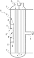
- Fig. 3 is an enlarged drawing of the part enclosed by dotted lines in Fig. 2A , intended to show in greater detail an aspect of the structure of the inlet pipe 120 and the anti-impact plate 204.
- the inlet pipe 120 is a round pipe with an internal diameter that gradually increases from an inlet 222 to the outlet 224, and has a central axis K.
- the inlet pipe 120 passes through an upper part of the housing 112, and the outlet 224 of the inlet pipe 120 is accommodated in the accommodating cavity 202.
- the inlet 222 of the inlet pipe 120 has internal diameter D 1
- the outlet 224 of the inlet pipe 120 has internal diameter D 2 ; the internal diameter of the inlet pipe 120 increases smoothly from the internal diameter D 1 of the inlet 222 to the internal diameter D 2 of the outlet 224.
- the outlet 224 of the inlet pipe 120 has a projected region S projected vertically downward along the central axis K of the inlet pipe 120.
- the projected region S is a hole-free zone, so that the refrigerant gas can flow past at least a part of an edge of the anti-impact plate 204 along an upper surface of the anti-impact plate 204 and then come into contact with the first tube bundle 242, thereby preventing the refrigerant gas from striking the first tube bundle 242 directly.
- Fig. 4 is a schematic drawing of part of an axial section of the inlet pipe 120 in Fig. 3 , intended to show the specific shape of an inner wall of the inlet pipe 120.
- x represents distance of the inner wall of the inlet pipe 120 on the axial section, in a direction perpendicular to the central axis K;
- y represents distance of the inner wall of the inlet pipe 120 on the axial section, in a direction parallel to the central axis K.
- a curve of the inner wall of the inlet pipe 120 satisfies any one or more of the following curves, wherein f, g, h, l, m, n, o, p, q, s, u and v represent constants:
- the smooth and gradual widening of the internal diameter of the inlet pipe 120 from the internal diameter D 1 of the inlet 222 to the internal diameter D 2 of the outlet 224 can reduce frictional loss of the refrigerant gas flowing into the inlet pipe 120, and this kind of gradually widening structure can also reduce local resistance of the refrigerant gas.
- the inlet pipe 120 is a pipe of equal thickness.
- the inlet pipe may also be a pipe of non-equal thickness.
- Fig. 5 is a schematic chart of the variation of a pressure recovery coefficient Cv of the inlet pipe 120 in Fig. 1 with respect to a ratio AreaRatio.
- the inlet 222 of the inlet pipe 120 has an inlet area A 1
- a surface formed by vertically downward extension of an edge of the outlet 224 of the inlet pipe 120 to the anti-impact plate (204) has an outlet extension area A 2
- the ratio AreaRatio represents the ratio of the inlet area A 1 to the outlet extension area A 2
- the pressure recovery coefficient Cv represents the ratio of conversion of dynamic pressure of the refrigerant gas entering the condenser 100 to static pressure. For example, when the pressure recovery coefficient Cv is 0.3, this indicates that 30% of dynamic pressure is converted to static pressure.
- the structural arrangement of the inlet pipe 120 and anti-impact plate 204 can cause the dynamic pressure of the refrigerant gas entering the condenser 100 to be partially converted to static pressure and reduce the static pressure loss when the refrigerant gas enters the tubular body 102 through the inlet 222, thereby increasing the condensing pressure of the refrigerant gas in the condenser 100, so as to enhance the heat exchange performance.
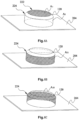
- Figs. 6A - 6C are schematic drawings of the relative positional relationship of the inlet pipe 120 and the anti-impact plate 204 in the condenser shown in Fig. 2A , wherein Fig. 6A is intended to show the inlet area A 1 of the inlet 222, and Figs. 6B - 6C are intended to show the outlet extension area A 2 .
- the shaded part in Fig. 6A indicates the inlet area A 1 of the inlet 222, wherein the inlet area A 1 is determined by the internal diameter D 1 of the inlet 222.
- the surface formed by vertically downward extension of the edge of the outlet 224 to the anti-impact plate 204 is an imaginary surface, which is a cylindrical surface and has the outlet extension area A 2 .
- the sum of a shaded part A 21 in Fig. 6B and a shaded part A 22 in Fig. 6C is the outlet extension area A 2 .
- the shaded part A 21 in Fig. 6B represents a part of the outlet extension area A 2 that is visible at the visual angle of Fig. 6B (which is the same as the visual angle of Fig. 6C )
- the shaded part A 22 in Fig. 6C represents another part of the outlet extension area A 2 that is not visible at the visual angle of Fig. 6C (which is the same as the visual angle of Fig. 6B ).
- the outlet extension area A 2 is related to the circumference of the outlet 224 and the gap H between the outlet 224 and the anti-impact plate 204.
- Fig. 7A is a sectional view, taken along section line A-A in Fig. 1 , of the condenser 100 according to another aspect of the present application.
- Fig. 7B is a sectional view, taken along section line B-B in Fig. 1 , of the condenser 100 in Fig. 7A .
- the configurations of all the other components are the same as in Figs. 2A - 2B , so are not described again here.
- two side edges of the anti-impact plate 204 in a width direction of the condenser 100 are bent upward, to form extension parts 702, 704 extending upward, and a connection with the housing 112 is made by means of the two side edges of the anti-impact plate 204 in the width direction of the condenser 100.
- Figs. 8A - 8C are schematic drawings of the relative positional relationship of the inlet pipe 120 and the anti-impact plate 204 in the aspect shown in Fig. 7A , wherein Fig. 8A is intended to show the inlet area A 1 of the inlet 222, and Figs. 8B - 8C are intended to show the outlet extension area A 2 of the surface formed by vertically downward extension of the edge of the outlet 224 to the anti-impact plate 204.
- the area A 1 of the inlet 222 shown in Fig. 8A and the method of calculation thereof are the same as in Fig. 6A , so are not described again here.
- the shaded part A 21 in Fig. 8B represents a part of the outlet extension area A 2 that is visible at the visual angle of Fig. 8B (which is the same as the visual angle of Fig. 8C )
- the shaded part A 22 in Fig. 8C represents a part of the outlet extension area A 2 that is obscured by the inlet pipe 120 at the visual angle of Fig. 8C (which is the same as the visual angle of Fig. 8B )
- the shaded part A 23 in Fig. 8C represents a part of the outlet extension area A 2 that is obscured by the extension part 704 of the anti-impact plate 204 at the visual angle of Fig. 8C (which is the same as the visual angle of Fig. 8B ).
- the surface of vertically downward extension of the edge of the outlet 224 to the anti-impact plate 204 is a cylindrical surface (i.e. annular).
- the surface formed by vertically downward extension of the edge of the outlet 224 to the anti-impact plate 204 is not a cylindrical surface.
- the surface formed by vertically downward extension of the edge of the outlet 224 strikes the extension parts 702, 704 of the anti-impact plate 204, so a cylindrical surface formed by vertically downward extension of the edge of the outlet 224 will have a part cut away by the extension parts 702, 704; thus, the surface formed by vertically downward extension of the edge of the outlet 224 is not cylindrical between the outlet 224 and the anti-impact plate 204. Therefore, the outlet extension area A 2 is not only related to the circumference of the outlet 224 and the gap H between the outlet 224 and the anti-impact plate 204, but also related to the structural shape of the anti-impact plate 204.
- Fig. 9 is a sectional view, taken along section line A-A in Fig. 1 , of the condenser 100 according to the invention.
- the configurations of all the other components are the same as in Figs. 2A - 2B , so are not described again here.
- the anti-impact plate 204 is provided with multiple holes 902; all of the multiple holes 902 are located outside the projected region S, on the anti-impact plate 204, of the outlet 224 of the inlet pipe 120, projected vertically downward along the central axis K of the inlet pipe 120, so that the refrigerant gas can flow toward the first tube bundle 242 more quickly via the multiple holes 902 after being blocked by the anti-impact plate 204.
- the anti-impact plate 204 is provided with the multiple holes 902, since the anti-impact plate 204 under the projected region S is still a flat plate, in the embodiment shown in Fig. 9 , the inlet area A 1 of the inlet 222 and the outlet extension area A 2 of vertically downward extension of the edge of the outlet 224 to the anti-impact plate 204 are calculated in the same way as that expounded in Fig. 7A .
- anti-impact plate in the present application is substantially configured as a flat plate in each case, those skilled in the art will understand that the anti-impact plate could also be designed to have another shape structure more favorable for the flow of refrigerant gas.
- the condenser in the present application is in each case described by taking a shell-and-tube condenser as an example, those skilled in the art will understand that based on the spirit of the present invention, the condenser can not only be a shell-and-tube condenser, but can also be another different form of condenser, such as a tube-in-tube condenser.
Landscapes
- Engineering & Computer Science (AREA)
- Physics & Mathematics (AREA)
- Mechanical Engineering (AREA)
- General Engineering & Computer Science (AREA)
- Thermal Sciences (AREA)
- Geometry (AREA)
- Heat-Exchange Devices With Radiators And Conduit Assemblies (AREA)
- Air-Conditioning For Vehicles (AREA)
Claims (4)
- Kondensator (100), umfassend:- ein Gehäuse (112), das einen Aufnahmehohlraum (202) aufweist;- ein Einlassrohr (120), wobei das Einlassrohr (120) ein rundes Rohr mit einem Innendurchmesser ist, der sich von einem Einlass (222) zu einem Auslass (224) allmählich erhöht, wobei das Einlassrohr (120) konfiguriert ist, durch einen oberen Teil des Gehäuses (112) hindurchzugehen, und der Auslass (224) des Einlassrohrs (120) in dem Aufnahmehohlraum (202) aufgenommen ist; und- eine Aufprallschutzplatte (204), die in dem Aufnahmehohlraum (202) aufgenommen ist und sich unterhalb des Auslasses (224) des Einlassrohrs (120) befindet, und eine Lücke (H), die zwischen der Aufprallschutzplatte (204) und dem Auslass (224) vorgesehen ist, wobei die Lücke den Durchfluss eines aus dem Auslass (224) strömenden Fluids ermöglicht,dadurch gekennzeichnet, dass
die Aufprallschutzplatte (204) mit mehreren Löchern (902) vorgesehen ist, die sich alle außerhalb einer vorstehenden Region (S) auf der Aufprallschutzplatte (204) befinden, wobei die vorstehende Region (S) dem Auslass (224) des Einlassrohrs (120) entspricht, der vertikal nach unten entlang einer mittleren Achse (K) des Einlassrohrs (120) vorsteht, und die vorstehende Region (S) eine lochfreie Zone ist. - Kondensator (100) nach Anspruch 1,
dadurch gekennzeichnet, dass
der Innendurchmesser des Einlassrohrs (120) vom Einlass (222) bis zum Auslass (224) gleichmäßig erhöht wird. - Kondensator (100) nach Anspruch 1 oder 2,
dadurch gekennzeichnet, dass
die Aufprallschutzplatte (204) so konfiguriert ist, dass das Fluid an mindestens einem Teil einer Kante der Aufprallschutzplatte (204) entlang einer oberen Oberfläche der Aufprallschutzplatte (204) strömt. - Kondensator (100) nach einem der Ansprüche 1 bis 3,
dadurch gekennzeichnet, dass
die Aufprallschutzplatte (204) mit dem Gehäuse (112) durch Mittel von zwei seitlichen Kanten der Aufprallschutzplatte (204) in einer Breitenrichtung des Kondensators (100) verbunden ist.
Applications Claiming Priority (3)
| Application Number | Priority Date | Filing Date | Title |
|---|---|---|---|
| CN201821214503.9U CN208872149U (zh) | 2018-07-27 | 2018-07-27 | 冷凝器 |
| CN201810843447.3A CN109141077A (zh) | 2018-07-27 | 2018-07-27 | 冷凝器 |
| PCT/CN2019/097919 WO2020020349A1 (zh) | 2018-07-27 | 2019-07-26 | 冷凝器 |
Publications (3)
| Publication Number | Publication Date |
|---|---|
| EP3832242A1 EP3832242A1 (de) | 2021-06-09 |
| EP3832242A4 EP3832242A4 (de) | 2022-04-06 |
| EP3832242B1 true EP3832242B1 (de) | 2024-09-18 |
Family
ID=69180807
Family Applications (1)
| Application Number | Title | Priority Date | Filing Date |
|---|---|---|---|
| EP19840963.3A Active EP3832242B1 (de) | 2018-07-27 | 2019-07-26 | Kondensator |
Country Status (4)
| Country | Link |
|---|---|
| US (1) | US12055326B2 (de) |
| EP (1) | EP3832242B1 (de) |
| KR (1) | KR102800889B1 (de) |
| WO (1) | WO2020020349A1 (de) |
Families Citing this family (4)
| Publication number | Priority date | Publication date | Assignee | Title |
|---|---|---|---|---|
| CN111928716A (zh) * | 2020-08-13 | 2020-11-13 | 中国核动力研究设计院 | 一种用于反应堆热交换器的导流装置 |
| EP4290613A4 (de) | 2021-03-22 | 2024-08-28 | Lg Chem, Ltd. | Kathodenaktivmaterial, kathode damit und lithiumsekundärbatterie |
| CN116465117B (zh) * | 2023-03-31 | 2026-04-28 | 约克(无锡)空调冷冻设备有限公司 | 冷凝器 |
| CN118376024B (zh) * | 2024-05-20 | 2025-11-14 | 约克(无锡)空调冷冻设备有限公司 | 冷凝器 |
Family Cites Families (21)
| Publication number | Priority date | Publication date | Assignee | Title |
|---|---|---|---|---|
| US2138469A (en) * | 1935-08-21 | 1938-11-29 | Alco Products Inc | Heat exchanger |
| US2607567A (en) * | 1940-07-31 | 1952-08-19 | James C Hobbs | Heat exchanger |
| US3180405A (en) * | 1959-03-11 | 1965-04-27 | Itt | Condensers |
| US4252186A (en) * | 1979-09-19 | 1981-02-24 | Borg-Warner Corporation | Condenser with improved heat transfer |
| US5465783A (en) * | 1994-03-04 | 1995-11-14 | Fedco Automotive Components Company, Inc. | Sacrificial erosion bridge for a heat exchanger |
| US6382313B2 (en) | 2000-02-25 | 2002-05-07 | Nippon Shokubai Co., Ltd. | Heat exchanger for easily polymerizing substance-containing gas provided with gas distributing plate |
| US6851277B1 (en) | 2003-08-27 | 2005-02-08 | Carrier Corporation | Economizer chamber for minimizing pressure pulsations |
| US20070028647A1 (en) * | 2005-08-04 | 2007-02-08 | York International | Condenser inlet diffuser |
| US8365812B2 (en) * | 2007-06-27 | 2013-02-05 | King Fahd University Of Petroleum And Minerals | Shell and tube heat exchanger |
| US8276653B2 (en) * | 2008-03-28 | 2012-10-02 | Saudi Arabian Oil Company | Raised overlapped impingement plate |
| DE102011013340A1 (de) * | 2010-12-30 | 2012-07-05 | Linde Aktiengesellschaft | Verteileinrichtung und Wärmetauschervorrichtung |
| CN106288523B (zh) | 2015-06-29 | 2019-09-13 | 约克(无锡)空调冷冻设备有限公司 | 冷凝和降膜蒸发混合换热器 |
| CN205279537U (zh) | 2015-12-31 | 2016-06-01 | 江森自控楼宇设备科技(无锡)有限公司 | 带外置过冷器的壳管式冷凝器 |
| CN205279536U (zh) | 2015-12-31 | 2016-06-01 | 江森自控楼宇设备科技(无锡)有限公司 | 带外置过冷器的壳管式冷凝器 |
| CN206113725U (zh) | 2016-08-31 | 2017-04-19 | 江苏明浩新能源发展有限公司 | 重质废油处理用冷凝器 |
| US10612823B2 (en) * | 2017-02-03 | 2020-04-07 | Daikin Applied Americas Inc. | Condenser |
| US10371422B2 (en) * | 2017-02-13 | 2019-08-06 | Daikin Applied Americas Inc. | Condenser with tube support structure |
| CN111630329B (zh) | 2017-10-10 | 2022-12-02 | 江森自控科技公司 | 加热、通风、空调和制冷系统、冷凝器及其设计方法 |
| CN208332761U (zh) * | 2018-01-16 | 2019-01-04 | 开利公司 | 用于冷凝器的导流板、具有其的冷凝器及制冷系统 |
| CN109141077A (zh) | 2018-07-27 | 2019-01-04 | 约克(无锡)空调冷冻设备有限公司 | 冷凝器 |
| CN208872149U (zh) | 2018-07-27 | 2019-05-17 | 约克(无锡)空调冷冻设备有限公司 | 冷凝器 |
-
2019
- 2019-07-26 WO PCT/CN2019/097919 patent/WO2020020349A1/zh not_active Ceased
- 2019-07-26 KR KR1020217005159A patent/KR102800889B1/ko active Active
- 2019-07-26 EP EP19840963.3A patent/EP3832242B1/de active Active
- 2019-07-26 US US17/263,844 patent/US12055326B2/en active Active
Also Published As
| Publication number | Publication date |
|---|---|
| EP3832242A1 (de) | 2021-06-09 |
| US20210310705A1 (en) | 2021-10-07 |
| WO2020020349A1 (zh) | 2020-01-30 |
| KR20210036940A (ko) | 2021-04-05 |
| EP3832242A4 (de) | 2022-04-06 |
| US12055326B2 (en) | 2024-08-06 |
| KR102800889B1 (ko) | 2025-04-24 |
Similar Documents
| Publication | Publication Date | Title |
|---|---|---|
| EP2369285B1 (de) | Wärmetauscher | |
| EP2392886B1 (de) | Ausrichtungsunabhängiges Kühlmittelverteilerrohr | |
| EP3832242A1 (de) | Kondensator | |
| US20080041093A1 (en) | Accumulator of air conditioner | |
| US10113813B2 (en) | Tube for heat exchanger | |
| JP2005516176A (ja) | 達磨型流路を有する熱交換器用チューブ及びこれを用いた熱交換器 | |
| US20150027672A1 (en) | Heat exchanger | |
| US10337808B2 (en) | Condenser | |
| JP2009063228A (ja) | 扁平状伝熱管 | |
| US7073571B2 (en) | Integrated condenser oil cooler with a receiver/dryer | |
| WO2014144105A1 (en) | Side mounted refrigerant distributor in a flooded evaporator and side mounted inlet pipe to the distributor | |
| JP2018189337A (ja) | 冷媒蒸発器およびその製造方法 | |
| EP3362759B1 (de) | Wärmetauscher für hlk-geräte im wohnbereich | |
| KR102653343B1 (ko) | 응축기 | |
| CN111220016A (zh) | 用于热交换器的收集管 | |
| US7290597B2 (en) | Heat exchanger | |
| JP5194279B2 (ja) | エバポレータ | |
| CN208872149U (zh) | 冷凝器 | |
| US20230280113A1 (en) | Heat exchanger | |
| JP4852307B2 (ja) | 熱交換器 | |
| EP1319908A1 (de) | Wärmetauscher | |
| JP5187047B2 (ja) | 熱交換器用チューブ | |
| CN109141077A (zh) | 冷凝器 | |
| KR100606332B1 (ko) | 공조기기의 열교환기용 납작튜브 | |
| JPH0359364A (ja) | 冷媒凝縮器及び冷媒凝縮器のチューブ群数の設定方法 |
Legal Events
| Date | Code | Title | Description |
|---|---|---|---|
| STAA | Information on the status of an ep patent application or granted ep patent |
Free format text: STATUS: THE INTERNATIONAL PUBLICATION HAS BEEN MADE |
|
| PUAI | Public reference made under article 153(3) epc to a published international application that has entered the european phase |
Free format text: ORIGINAL CODE: 0009012 |
|
| STAA | Information on the status of an ep patent application or granted ep patent |
Free format text: STATUS: REQUEST FOR EXAMINATION WAS MADE |
|
| 17P | Request for examination filed |
Effective date: 20210212 |
|
| AK | Designated contracting states |
Kind code of ref document: A1 Designated state(s): AL AT BE BG CH CY CZ DE DK EE ES FI FR GB GR HR HU IE IS IT LI LT LU LV MC MK MT NL NO PL PT RO RS SE SI SK SM TR |
|
| DAV | Request for validation of the european patent (deleted) | ||
| DAX | Request for extension of the european patent (deleted) | ||
| A4 | Supplementary search report drawn up and despatched |
Effective date: 20220307 |
|
| RIC1 | Information provided on ipc code assigned before grant |
Ipc: F25B 39/04 20060101ALI20220301BHEP Ipc: F28F 9/02 20060101ALI20220301BHEP Ipc: F28D 7/16 20060101AFI20220301BHEP |
|
| STAA | Information on the status of an ep patent application or granted ep patent |
Free format text: STATUS: EXAMINATION IS IN PROGRESS |
|
| 17Q | First examination report despatched |
Effective date: 20230724 |
|
| GRAP | Despatch of communication of intention to grant a patent |
Free format text: ORIGINAL CODE: EPIDOSNIGR1 |
|
| STAA | Information on the status of an ep patent application or granted ep patent |
Free format text: STATUS: GRANT OF PATENT IS INTENDED |
|
| INTG | Intention to grant announced |
Effective date: 20240411 |
|
| GRAS | Grant fee paid |
Free format text: ORIGINAL CODE: EPIDOSNIGR3 |
|
| GRAA | (expected) grant |
Free format text: ORIGINAL CODE: 0009210 |
|
| STAA | Information on the status of an ep patent application or granted ep patent |
Free format text: STATUS: THE PATENT HAS BEEN GRANTED |
|
| AK | Designated contracting states |
Kind code of ref document: B1 Designated state(s): AL AT BE BG CH CY CZ DE DK EE ES FI FR GB GR HR HU IE IS IT LI LT LU LV MC MK MT NL NO PL PT RO RS SE SI SK SM TR |
|
| REG | Reference to a national code |
Ref country code: GB Ref legal event code: FG4D |
|
| REG | Reference to a national code |
Ref country code: CH Ref legal event code: EP |
|
| REG | Reference to a national code |
Ref country code: DE Ref legal event code: R096 Ref document number: 602019059207 Country of ref document: DE |
|
| REG | Reference to a national code |
Ref country code: IE Ref legal event code: FG4D |
|
| REG | Reference to a national code |
Ref country code: LT Ref legal event code: MG9D |
|
| PG25 | Lapsed in a contracting state [announced via postgrant information from national office to epo] |
Ref country code: NO Free format text: LAPSE BECAUSE OF FAILURE TO SUBMIT A TRANSLATION OF THE DESCRIPTION OR TO PAY THE FEE WITHIN THE PRESCRIBED TIME-LIMIT Effective date: 20241218 |
|
| PG25 | Lapsed in a contracting state [announced via postgrant information from national office to epo] |
Ref country code: GR Free format text: LAPSE BECAUSE OF FAILURE TO SUBMIT A TRANSLATION OF THE DESCRIPTION OR TO PAY THE FEE WITHIN THE PRESCRIBED TIME-LIMIT Effective date: 20241219 Ref country code: FI Free format text: LAPSE BECAUSE OF FAILURE TO SUBMIT A TRANSLATION OF THE DESCRIPTION OR TO PAY THE FEE WITHIN THE PRESCRIBED TIME-LIMIT Effective date: 20240918 |
|
| PG25 | Lapsed in a contracting state [announced via postgrant information from national office to epo] |
Ref country code: BG Free format text: LAPSE BECAUSE OF FAILURE TO SUBMIT A TRANSLATION OF THE DESCRIPTION OR TO PAY THE FEE WITHIN THE PRESCRIBED TIME-LIMIT Effective date: 20240918 |
|
| PG25 | Lapsed in a contracting state [announced via postgrant information from national office to epo] |
Ref country code: LV Free format text: LAPSE BECAUSE OF FAILURE TO SUBMIT A TRANSLATION OF THE DESCRIPTION OR TO PAY THE FEE WITHIN THE PRESCRIBED TIME-LIMIT Effective date: 20240918 |
|
| PG25 | Lapsed in a contracting state [announced via postgrant information from national office to epo] |
Ref country code: HR Free format text: LAPSE BECAUSE OF FAILURE TO SUBMIT A TRANSLATION OF THE DESCRIPTION OR TO PAY THE FEE WITHIN THE PRESCRIBED TIME-LIMIT Effective date: 20240918 |
|
| REG | Reference to a national code |
Ref country code: NL Ref legal event code: MP Effective date: 20240918 |
|
| PG25 | Lapsed in a contracting state [announced via postgrant information from national office to epo] |
Ref country code: RS Free format text: LAPSE BECAUSE OF FAILURE TO SUBMIT A TRANSLATION OF THE DESCRIPTION OR TO PAY THE FEE WITHIN THE PRESCRIBED TIME-LIMIT Effective date: 20241218 |
|
| PG25 | Lapsed in a contracting state [announced via postgrant information from national office to epo] |
Ref country code: RS Free format text: LAPSE BECAUSE OF FAILURE TO SUBMIT A TRANSLATION OF THE DESCRIPTION OR TO PAY THE FEE WITHIN THE PRESCRIBED TIME-LIMIT Effective date: 20241218 Ref country code: NO Free format text: LAPSE BECAUSE OF FAILURE TO SUBMIT A TRANSLATION OF THE DESCRIPTION OR TO PAY THE FEE WITHIN THE PRESCRIBED TIME-LIMIT Effective date: 20241218 Ref country code: LV Free format text: LAPSE BECAUSE OF FAILURE TO SUBMIT A TRANSLATION OF THE DESCRIPTION OR TO PAY THE FEE WITHIN THE PRESCRIBED TIME-LIMIT Effective date: 20240918 Ref country code: HR Free format text: LAPSE BECAUSE OF FAILURE TO SUBMIT A TRANSLATION OF THE DESCRIPTION OR TO PAY THE FEE WITHIN THE PRESCRIBED TIME-LIMIT Effective date: 20240918 Ref country code: GR Free format text: LAPSE BECAUSE OF FAILURE TO SUBMIT A TRANSLATION OF THE DESCRIPTION OR TO PAY THE FEE WITHIN THE PRESCRIBED TIME-LIMIT Effective date: 20241219 Ref country code: FI Free format text: LAPSE BECAUSE OF FAILURE TO SUBMIT A TRANSLATION OF THE DESCRIPTION OR TO PAY THE FEE WITHIN THE PRESCRIBED TIME-LIMIT Effective date: 20240918 Ref country code: BG Free format text: LAPSE BECAUSE OF FAILURE TO SUBMIT A TRANSLATION OF THE DESCRIPTION OR TO PAY THE FEE WITHIN THE PRESCRIBED TIME-LIMIT Effective date: 20240918 |
|
| REG | Reference to a national code |
Ref country code: AT Ref legal event code: MK05 Ref document number: 1725015 Country of ref document: AT Kind code of ref document: T Effective date: 20240918 |
|
| PG25 | Lapsed in a contracting state [announced via postgrant information from national office to epo] |
Ref country code: NL Free format text: LAPSE BECAUSE OF FAILURE TO SUBMIT A TRANSLATION OF THE DESCRIPTION OR TO PAY THE FEE WITHIN THE PRESCRIBED TIME-LIMIT Effective date: 20240918 |
|
| PG25 | Lapsed in a contracting state [announced via postgrant information from national office to epo] |
Ref country code: PT Free format text: LAPSE BECAUSE OF FAILURE TO SUBMIT A TRANSLATION OF THE DESCRIPTION OR TO PAY THE FEE WITHIN THE PRESCRIBED TIME-LIMIT Effective date: 20250120 Ref country code: IS Free format text: LAPSE BECAUSE OF FAILURE TO SUBMIT A TRANSLATION OF THE DESCRIPTION OR TO PAY THE FEE WITHIN THE PRESCRIBED TIME-LIMIT Effective date: 20250118 |
|
| PG25 | Lapsed in a contracting state [announced via postgrant information from national office to epo] |
Ref country code: SM Free format text: LAPSE BECAUSE OF FAILURE TO SUBMIT A TRANSLATION OF THE DESCRIPTION OR TO PAY THE FEE WITHIN THE PRESCRIBED TIME-LIMIT Effective date: 20240918 Ref country code: RO Free format text: LAPSE BECAUSE OF FAILURE TO SUBMIT A TRANSLATION OF THE DESCRIPTION OR TO PAY THE FEE WITHIN THE PRESCRIBED TIME-LIMIT Effective date: 20240918 |
|
| PG25 | Lapsed in a contracting state [announced via postgrant information from national office to epo] |
Ref country code: ES Free format text: LAPSE BECAUSE OF FAILURE TO SUBMIT A TRANSLATION OF THE DESCRIPTION OR TO PAY THE FEE WITHIN THE PRESCRIBED TIME-LIMIT Effective date: 20240918 |
|
| PG25 | Lapsed in a contracting state [announced via postgrant information from national office to epo] |
Ref country code: EE Free format text: LAPSE BECAUSE OF FAILURE TO SUBMIT A TRANSLATION OF THE DESCRIPTION OR TO PAY THE FEE WITHIN THE PRESCRIBED TIME-LIMIT Effective date: 20240918 Ref country code: AT Free format text: LAPSE BECAUSE OF FAILURE TO SUBMIT A TRANSLATION OF THE DESCRIPTION OR TO PAY THE FEE WITHIN THE PRESCRIBED TIME-LIMIT Effective date: 20240918 |
|
| PG25 | Lapsed in a contracting state [announced via postgrant information from national office to epo] |
Ref country code: CZ Free format text: LAPSE BECAUSE OF FAILURE TO SUBMIT A TRANSLATION OF THE DESCRIPTION OR TO PAY THE FEE WITHIN THE PRESCRIBED TIME-LIMIT Effective date: 20240918 Ref country code: PL Free format text: LAPSE BECAUSE OF FAILURE TO SUBMIT A TRANSLATION OF THE DESCRIPTION OR TO PAY THE FEE WITHIN THE PRESCRIBED TIME-LIMIT Effective date: 20240918 |
|
| PG25 | Lapsed in a contracting state [announced via postgrant information from national office to epo] |
Ref country code: SK Free format text: LAPSE BECAUSE OF FAILURE TO SUBMIT A TRANSLATION OF THE DESCRIPTION OR TO PAY THE FEE WITHIN THE PRESCRIBED TIME-LIMIT Effective date: 20240918 Ref country code: IT Free format text: LAPSE BECAUSE OF FAILURE TO SUBMIT A TRANSLATION OF THE DESCRIPTION OR TO PAY THE FEE WITHIN THE PRESCRIBED TIME-LIMIT Effective date: 20240918 |
|
| REG | Reference to a national code |
Ref country code: DE Ref legal event code: R097 Ref document number: 602019059207 Country of ref document: DE |
|
| PG25 | Lapsed in a contracting state [announced via postgrant information from national office to epo] |
Ref country code: DK Free format text: LAPSE BECAUSE OF FAILURE TO SUBMIT A TRANSLATION OF THE DESCRIPTION OR TO PAY THE FEE WITHIN THE PRESCRIBED TIME-LIMIT Effective date: 20240918 |
|
| PLBE | No opposition filed within time limit |
Free format text: ORIGINAL CODE: 0009261 |
|
| STAA | Information on the status of an ep patent application or granted ep patent |
Free format text: STATUS: NO OPPOSITION FILED WITHIN TIME LIMIT |
|
| 26N | No opposition filed |
Effective date: 20250619 |
|
| PG25 | Lapsed in a contracting state [announced via postgrant information from national office to epo] |
Ref country code: SE Free format text: LAPSE BECAUSE OF FAILURE TO SUBMIT A TRANSLATION OF THE DESCRIPTION OR TO PAY THE FEE WITHIN THE PRESCRIBED TIME-LIMIT Effective date: 20240918 |
|
| PGFP | Annual fee paid to national office [announced via postgrant information from national office to epo] |
Ref country code: FR Payment date: 20250725 Year of fee payment: 7 |
|
| REG | Reference to a national code |
Ref country code: DE Ref legal event code: R119 Ref document number: 602019059207 Country of ref document: DE |
|
| REG | Reference to a national code |
Ref country code: CH Ref legal event code: H13 Free format text: ST27 STATUS EVENT CODE: U-0-0-H10-H13 (AS PROVIDED BY THE NATIONAL OFFICE) Effective date: 20260224 |
|
| PG25 | Lapsed in a contracting state [announced via postgrant information from national office to epo] |
Ref country code: LU Free format text: LAPSE BECAUSE OF NON-PAYMENT OF DUE FEES Effective date: 20250726 |
|
| GBPC | Gb: european patent ceased through non-payment of renewal fee |
Effective date: 20250726 |
|
| REG | Reference to a national code |
Ref country code: BE Ref legal event code: MM Effective date: 20250731 |
|
| PG25 | Lapsed in a contracting state [announced via postgrant information from national office to epo] |
Ref country code: GB Free format text: LAPSE BECAUSE OF NON-PAYMENT OF DUE FEES Effective date: 20250726 |
|
| PG25 | Lapsed in a contracting state [announced via postgrant information from national office to epo] |
Ref country code: DE Free format text: LAPSE BECAUSE OF NON-PAYMENT OF DUE FEES Effective date: 20260203 |
|
| PG25 | Lapsed in a contracting state [announced via postgrant information from national office to epo] |
Ref country code: BE Free format text: LAPSE BECAUSE OF NON-PAYMENT OF DUE FEES Effective date: 20250731 |
|
| PG25 | Lapsed in a contracting state [announced via postgrant information from national office to epo] |
Ref country code: CH Free format text: LAPSE BECAUSE OF NON-PAYMENT OF DUE FEES Effective date: 20250731 |