EP3832324A1 - Agencement de circuit à tension de mesure active permettant de déterminer la résistance d'isolation par rapport à la terre dans un système d'alimentation en courant non mis à la terre - Google Patents
Agencement de circuit à tension de mesure active permettant de déterminer la résistance d'isolation par rapport à la terre dans un système d'alimentation en courant non mis à la terre Download PDFInfo
- Publication number
- EP3832324A1 EP3832324A1 EP20208363.0A EP20208363A EP3832324A1 EP 3832324 A1 EP3832324 A1 EP 3832324A1 EP 20208363 A EP20208363 A EP 20208363A EP 3832324 A1 EP3832324 A1 EP 3832324A1
- Authority
- EP
- European Patent Office
- Prior art keywords
- measuring
- power supply
- sub
- voltage
- circuit arrangement
- Prior art date
- Legal status (The legal status is an assumption and is not a legal conclusion. Google has not performed a legal analysis and makes no representation as to the accuracy of the status listed.)
- Granted
Links
Images




Classifications
-
- G—PHYSICS
- G01—MEASURING; TESTING
- G01R—MEASURING ELECTRIC VARIABLES; MEASURING MAGNETIC VARIABLES
- G01R27/00—Arrangements for measuring resistance, reactance, impedance, or electric characteristics derived therefrom
- G01R27/02—Measuring real or complex resistance, reactance, impedance, or other two-pole characteristics derived therefrom, e.g. time constant
- G01R27/16—Measuring impedance of element or network through which a current is passing from another source, e.g. cable, power line
- G01R27/18—Measuring resistance to earth, i.e. line to ground
-
- G—PHYSICS
- G01—MEASURING; TESTING
- G01R—MEASURING ELECTRIC VARIABLES; MEASURING MAGNETIC VARIABLES
- G01R27/00—Arrangements for measuring resistance, reactance, impedance, or electric characteristics derived therefrom
- G01R27/02—Measuring real or complex resistance, reactance, impedance, or other two-pole characteristics derived therefrom, e.g. time constant
- G01R27/025—Measuring very high resistances, e.g. isolation resistances, i.e. megohm-meters
-
- G—PHYSICS
- G01—MEASURING; TESTING
- G01R—MEASURING ELECTRIC VARIABLES; MEASURING MAGNETIC VARIABLES
- G01R27/00—Arrangements for measuring resistance, reactance, impedance, or electric characteristics derived therefrom
- G01R27/02—Measuring real or complex resistance, reactance, impedance, or other two-pole characteristics derived therefrom, e.g. time constant
- G01R27/08—Measuring resistance by measuring both voltage and current
-
- G—PHYSICS
- G01—MEASURING; TESTING
- G01R—MEASURING ELECTRIC VARIABLES; MEASURING MAGNETIC VARIABLES
- G01R31/00—Arrangements for testing electric properties; Arrangements for locating electric faults; Arrangements for electrical testing characterised by what is being tested not provided for elsewhere
-
- G—PHYSICS
- G01—MEASURING; TESTING
- G01R—MEASURING ELECTRIC VARIABLES; MEASURING MAGNETIC VARIABLES
- G01R31/00—Arrangements for testing electric properties; Arrangements for locating electric faults; Arrangements for electrical testing characterised by what is being tested not provided for elsewhere
- G01R31/50—Testing of electric apparatus, lines, cables or components for short-circuits, continuity, leakage current or incorrect line connections
- G01R31/52—Testing for short-circuits, leakage current or ground faults
Definitions
- the invention relates to a circuit arrangement with an active measuring voltage for determining an insulation resistance or a complex-valued insulation impedance of an ungrounded power supply system with respect to earth potential, with a measuring path running between an active conductor of the power supply system and the earth potential, a measuring voltage generator for generating the measuring voltage, a measuring resistor for tapping a measured voltage and a coupling resistor, and with a signal evaluation circuit which has a signal input for evaluating the measured voltage and a ground connection.
- the network form of an ungrounded power supply system is used, which is also referred to as an isolated network or an IT power supply system (French: Isole Terre - IT).
- IT power supply system In this type of power supply system, its active parts are separated from the earth potential - opposite "earth".
- first fault such as an earth fault in an active conductor in the power supply system
- the ungrounded power supply system considered in the context of the invention can be an alternating current or a direct current system or a mixed form of both systems.
- insulation resistance - in the event of a fault also insulation fault resistance or fault resistance must therefore be properly monitored with a standard-compliant insulation monitoring device (IMD), as a possible further fault on another active conductor (second fault ) a fault loop would arise and the fault current flowing in connection with an overcurrent protective device would result in the system being shut down with an operational standstill.
- IMD insulation monitoring device
- active insulation monitoring devices are known from the prior art. These have a measuring path running between one or more active conductors of the power supply system and the earth potential, which comprises an internal measuring voltage generator. A measuring voltage generated by the measuring voltage generator actively drives a measuring current via the active conductor (s) and via the insulation resistor back into the measuring path, which contains a measuring resistor connected in series with the measuring voltage generator for tapping a measured voltage and a series connected coupling resistor for coupling to the power supply system having. The one above the measuring resistor Taken voltage drop is fed to a signal evaluation circuit for evaluation via a signal input to determine the insulation resistance.
- a single-pole coupling with exactly one measuring path to just one active conductor is sufficient.
- a coupling with at least two measuring paths can be useful in order to also be able to measure a mains and displacement voltage and to implement coupling monitoring.
- the series connection of the measuring path is set up in such a way that the ground connection of the signal evaluation circuit is not connected to ground potential. All interface signals of the insulation monitoring devices are therefore superimposed with the (common-mode) measuring voltage to earth and must be transmitted in an electrically isolated manner when integrated into the ungrounded power supply system. There must therefore be no galvanic connection between the insulation monitoring devices and other earthed devices.
- these galvanically isolated interfaces represent a considerable cost factor, especially since they have to be implemented in every insulation monitoring device. For example, relays are used for forwarding alarm messages or for digital interfaces Data coupler required to achieve galvanic isolation.
- the present invention is therefore based on the object of describing a circuit arrangement with an active measuring voltage for determining the insulation resistance or for determining the complex insulation impedance as well as its possible uses for an ungrounded power supply system, with elaborate galvanic separation between insulation monitoring devices when they are coupled.
- the basic idea of the present invention is thus based on connecting the ground connection of the signal evaluation circuit to ground potential. Because there is no potential gradient in this way, interference currents (signal looping) can be prevented. Galvanic isolation is no longer required for all analog and digital interfaces. By dispensing with the galvanic separation of all interfaces of the signal evaluation circuit, including their voltage supply to earth, insulation monitoring devices can be coupled without the measurement being falsified by disruptive loop currents.
- the measuring path is advantageously equipped in such a way that the ground potential, the measuring voltage generator, the measuring resistor and the coupling resistor form a series circuit in a first sequence.
- the elements of the measuring path that is to say the measuring path elements measuring voltage generator, measuring resistor and coupling resistor, starting from the ground potential in a first sequence starting with the measuring voltage generator, followed by the Measuring resistor and then the coupling resistor are arranged.
- this first measuring arrangement there is a connection of the measuring voltage generator together with the ground connection of the signal evaluation circuit at ground potential.
- the voltage measured just a few volts (order of magnitude ⁇ 2 volts) across the measuring resistor is superimposed by the larger (common-mode) measurement voltage (order of magnitude ⁇ 20 volts), so that the signal evaluation circuit has to work with high common-mode rejection for the measured voltages.
- a multi-pole coupling is provided in an ungrounded power supply system with at least two conductors, with at least two of the active conductors each being connected to the ground potential via a measuring path.
- the measurement paths can be implemented completely separately, that is, each with its own measurement voltage generator, a measurement resistor and a coupling resistor, or at least two measurement paths can have a common measurement voltage generator.
- the measuring path is designed in a second sequence in such a way that, starting from the ground potential, the measuring resistor, the measuring voltage generator and the coupling resistor form a series circuit.
- the (common-mode) measurement voltage is recorded differentially.
- the common-mode rejection does not have to meet high requirements, since the differentially recorded measurement voltage is considerably greater than the voltage measured across the measurement resistor.
- this can be implemented in an ungrounded power supply system with at least two active conductors in such a way that at least two of the active conductors are each connected separately to the earth potential via a measuring path.
- the measuring voltage generators arranged in the respective measuring paths generate different measuring voltages in order to check the functionality of the coupling.
- connection monitoring so that, for example, line interruptions in the measurement paths can be detected.
- the respective driving measuring voltages of the measuring paths are identical, the measuring current driven by the respective measuring voltage should therefore also be identical in the coupling paths. If the measurement voltages differ between the measurement paths, they generate one if the coupling is intact Current across the source and load impedance. If this current does not match an expected current flow that can be determined from the existing load constellations and network properties, an interrupted connection of the measurement path can be detected in this way.
- the circuit arrangement with multi-pole coupling via separate measurement paths can advantageously be used for simultaneous, active measurement of a respective insulation resistance or a complex-valued insulation impedance to ground potential in several ungrounded power supply systems, with the measurement paths of active conductors from different power supply systems being assigned.
- Independent power supply systems are networks that each have mains voltage sources isolated from one another and their own loads.
- the respective insulation resistance can be determined for each independent network.
- the respective power supply systems are advantageously subjected to different measurement voltages.
- This configuration enables insulation resistance or insulation impedance determination between two independent power supply systems.
- a current flow is established between the power supply systems via the measurement paths, so that an unintentional low-resistance connection ("cross fault") of the power supply networks can be detected and the elements of this "cross fault" can be determined according to real and imaginary parts.
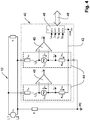
- Fig. 1 shows the basic structure of a circuit arrangement 10 for determining the insulation resistance (insulation monitoring device) of an ungrounded power supply system 12.
- a mains voltage source V N supplies a load R L via two active conductors L1, L2.
- the insulation monitoring device 10 is connected between the two active conductors L1, L2 and earth (earth potential) PE, which is coupled to the active conductors L1, L2 via a branched measuring path 14, so that a closed measuring circuit is established via the active conductors L1, L2 and can form the insulation resistance R F.
- the power supply system 12 is additionally described by a leakage capacitance C E modeled parallel to the insulation resistance R F , which together with the insulation resistance R F forms a complex-valued insulation impedance Z F. In a simplified representation, this complex-valued insulation impedance Z F is only shown for the active conductor L2, but in principle every active conductor L1, L2 has one.
- the measuring path 14 comprises a measuring voltage generator V G , a measuring resistor R M and a coupling resistor R A (V G , R M , R A and S A are intended here and below to represent all measuring path elements V Gi , R with the same effect Mi , R Ai and S Ai ).
- a switch S A for separating the insulation monitoring device 10 from the ungrounded power supply system 12 is provided in each measuring path 14.
- the measuring voltage generator V G generates a measuring voltage U G , which drives a current in the measuring circuit that closes via the insulation resistor R F , which leads to a measurable voltage drop (measured voltage) U M at the measuring resistor R M.
- the measurement voltage U G and the measured voltage U M are fed to a signal evaluation circuit 16 in order to determine the insulation resistance R F.
- the signal evaluation circuit 16 has an analog-to-digital converter ADC and a microcontroller for digital signal processing of the input signals ⁇ C and an interface 18, for example for outputting an alarm signal.
- Fig. 2 shows a circuit arrangement 20 according to the invention, with the measuring voltage generator V G , the measuring resistor R M and the coupling resistor R A forming a series circuit in a first sequence in the branched measuring paths 24, starting from the ground potential PE.
- a ground connection GND of the signal evaluation circuit 26 is connected to the ground potential PE via a galvanic connection 22.
- the two measuring paths 24 have a common measuring voltage generator V G.
- each measuring path 24 can also have its own measuring voltage generator V G.
- a high common-mode rejection is required to determine the measured voltage U M recorded by a differential amplifier 25 (instrumentation amplifier), since the (small) measured voltage U M is superimposed by a (large) common-mode measurement voltage U G.
- the measured voltage U M is in the order of magnitude of + -2 volts compared to the measurement voltage U G , which is in the order of magnitude of + -20 volts - would be an instrumentation amplifier with a common mode rejection of at least 120 dB for correct determination the measured voltage U M is required.
- the Figures 3a and 3b show two ways of doing this.
- the differential amplifier circuit 34 Fig. 3a
- the signal processing 36 Figure 3b
- the measured voltage U M a galvanic isolation 32 can be provided.
- Fig. 4 shows a circuit arrangement 40 according to the invention for determining the insulation resistance R F in an ungrounded power supply system 12 with multi-pole coupling.
- the measuring path elements are arranged in a second sequence measuring resistor R M , measuring voltage generator V G and coupling resistor R A in measuring paths 44.
- the measured voltages U M are recorded as a voltage drop across the respective measuring resistor R M directly to earth PE and fed to the signal evaluation unit 46 together with the differentially recorded measured voltages U G via a differential amplifier 45.
- the signal evaluation unit 46 is connected to the ground potential PE via a galvanic connection 42.
- the measurement voltage U G is required to determine the insulation resistance R F.
- a continuous, synchronous acquisition of the measurement voltage U G for tapping the measured voltage U M is not required. For example, by closing a switch S G arranged in parallel to the series circuit comprising the measuring voltage generator V G and the measuring resistor R M , as in FIG Figure 5a shown, the measurement voltage U G can be determined by means of the signal evaluation circuit 26, 46 for the measured voltage U M.
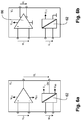
- the Figures 6a and 6b show a measuring voltage generator V G with an electrically isolated supply.
- the measurement voltage generator V G In order to avoid measurement-falsifying cross currents via the measurement voltage generator V G past the measurement resistor R M to the ground connection GND, the measurement voltage generator V G must have a galvanically isolated supply and high-resistance inputs for the control. If the control of the measurement voltage generator V G is to take place via an analog signal and the measurement voltage U G is to be bipolar, then as in Figure 6a shown, the measurement voltage source V G can be set up with a bipolar differential amplifier supplied by the voltages V CC or V DD.
- the supply voltage U GS supplies an internal, electrically isolated voltage source 62.
- a control voltage U GE controls the bipolar measurement voltage U G.
- the complexity of the internal, galvanically isolated voltage source 62 can be reduced by using a differential amplifier 66 with a differential output.
- This type of amplifier produces, as in Figure 6b shown, the bipolar measurement voltage U G even with a non-polar supply.
- Fig. 7 shows an application of the circuit arrangement 40 according to the invention in the second order Fig. 4 in two independent power supply systems 12.
- An active conductor L1 from the two mutually independent power supply systems 12 is assigned to each of the two measurement paths 44, so that the respective insulation resistances R F of the power supply systems 12 can be determined in the signal evaluation unit 46 independently of one another.
- This circuit configuration thus makes it possible to determine the respective insulation resistance R F for several independent power supply systems 12 simultaneously with only one circuit arrangement 40 according to the invention, whereby more than the two power supply systems 12 shown here by way of example can be monitored simultaneously.
- a multi-pole coupling to the respective power supply system 12 is also possible.
Landscapes
- Physics & Mathematics (AREA)
- General Physics & Mathematics (AREA)
- Testing Of Short-Circuits, Discontinuities, Leakage, Or Incorrect Line Connections (AREA)
- Measurement Of Resistance Or Impedance (AREA)
Applications Claiming Priority (1)
| Application Number | Priority Date | Filing Date | Title |
|---|---|---|---|
| DE102019132242.1A DE102019132242B4 (de) | 2019-11-28 | 2019-11-28 | Verwendungen einer Schaltungsanordnung mit aktiver Messspannung zur Bestimmung eines Isolationswiderstands in einem oder mehreren ungeerdeten Stromversorgungssystem(en) |
Publications (2)
| Publication Number | Publication Date |
|---|---|
| EP3832324A1 true EP3832324A1 (fr) | 2021-06-09 |
| EP3832324B1 EP3832324B1 (fr) | 2024-03-13 |
Family
ID=73475987
Family Applications (1)
| Application Number | Title | Priority Date | Filing Date |
|---|---|---|---|
| EP20208363.0A Active EP3832324B1 (fr) | 2019-11-28 | 2020-11-18 | Agencement de circuit à tension de mesure active permettant de déterminer la résistance d'isolation par rapport à la terre dans un système d'alimentation en courant non mis à la terre |
Country Status (4)
| Country | Link |
|---|---|
| US (1) | US11353486B2 (fr) |
| EP (1) | EP3832324B1 (fr) |
| CN (2) | CN112858785B (fr) |
| DE (1) | DE102019132242B4 (fr) |
Cited By (2)
| Publication number | Priority date | Publication date | Assignee | Title |
|---|---|---|---|---|
| DE102021132161B3 (de) | 2021-12-07 | 2023-06-07 | Bender Gmbh & Co. Kg | Verfahren und Einrichtung zur Impedanzüberwachung zum Schutz gegen elektrischen Schlag |
| EP4575525A1 (fr) * | 2023-12-20 | 2025-06-25 | Bender GmbH & Co. KG | Dispositif de mesure et procédé de mesure pour mesurer une impédance de broyage dans un système d'alimentation électrique non mis à la terre |
Families Citing this family (6)
| Publication number | Priority date | Publication date | Assignee | Title |
|---|---|---|---|---|
| DE102018121979A1 (de) * | 2018-09-10 | 2020-03-12 | Bender Gmbh & Co. Kg | Verfahren zur Isolationsüberwachung eines Umrichter-gespeisten Stromversorgungssystems |
| DE102019132242B4 (de) * | 2019-11-28 | 2021-06-17 | Bender Gmbh & Co. Kg | Verwendungen einer Schaltungsanordnung mit aktiver Messspannung zur Bestimmung eines Isolationswiderstands in einem oder mehreren ungeerdeten Stromversorgungssystem(en) |
| GB2600207B (en) * | 2021-06-18 | 2023-05-10 | Viper Innovations Ltd | Remote calculation of earth connection impedance |
| DE102022106394B3 (de) * | 2022-03-18 | 2023-08-17 | Bender Gmbh & Co. Kg | Verfahren und Überwachungseinrichtung zur Bestimmung einesTeil-Isolationswiderstands und einer Teil-Netzableitkapazität in einem verzweigten ungeerdeten Stromversorgungssystem |
| US12449456B2 (en) * | 2022-06-08 | 2025-10-21 | Sungrow Power Supply Co., Ltd. | Inverter and method for detecting insulation impedance of inverter |
| DE102023107987B3 (de) * | 2023-03-29 | 2024-07-25 | Bender Gmbh & Co. Kg | Verfahren zur Bestimmung eines Isolationswiderstands und einer Ableitkapazität eines ungeerdeten Stromversorgungssystems |
Citations (3)
| Publication number | Priority date | Publication date | Assignee | Title |
|---|---|---|---|---|
| DE3346387A1 (de) * | 1983-12-22 | 1985-07-04 | Standard Elektrik Lorenz Ag, 7000 Stuttgart | Schaltungsanordnung zur erd- und koerperschlussueberwachung |
| DE102011050590A1 (de) * | 2011-05-24 | 2012-11-29 | Sma Solar Technology Ag | Isolationsüberwachung mit einem Prüfsignal variabler Frequenz |
| DE102012019094A1 (de) * | 2012-09-27 | 2014-03-27 | E. Dold & Söhne KG | Verfahren und Einrichtung zur Überwachung eines Isolationswiderstandes von Netzen |
Family Cites Families (10)
| Publication number | Priority date | Publication date | Assignee | Title |
|---|---|---|---|---|
| DE2545325C3 (de) * | 1975-10-09 | 1979-03-22 | Siemens Ag, 1000 Berlin Und 8000 Muenchen | Schaltungsanordnung zur Messung des Isolationswiderstandes erdfreier Starkstromschaltungen |
| FR2978556B1 (fr) * | 2011-07-29 | 2014-03-07 | Schneider Electric Ind Sas | Dispositif de surveillance d'un conducteur de terre avec mesure de l'impedance |
| DE102012218107B4 (de) * | 2012-10-04 | 2023-04-27 | Bender Gmbh & Co. Kg | Verfahren zur Überwachung und Messung eines Isolationswiderstands mit einem störresistenten Messsignal und zugehöriger Signalgenerator |
| DE102014201044B3 (de) * | 2014-01-21 | 2015-03-05 | Bender Gmbh & Co. Kg | Isolationsüberwachungsvorrichtung zur simultanen Überwachung von Netzabschnitten eines ungeerdeten Stromversorgungssystems |
| DE102015207456B3 (de) * | 2015-04-23 | 2016-09-22 | Bender Gmbh & Co. Kg | Isolationsüberwachungsgerät mit Spannungsüberwachung und zugrunde liegendes Verfahren |
| FR3037406B1 (fr) * | 2015-06-15 | 2017-06-02 | Renault Sas | Systeme electrique comportant un circuit de detection d’un defaut d’isolement electrique |
| CN105119257B (zh) | 2015-07-25 | 2017-08-22 | 李景禄 | 一种配电网单相过渡电阻接地故障的动态处理方法 |
| EP3175761B1 (fr) * | 2015-12-02 | 2018-08-29 | Whirlpool Corporation | Procédé pour détecter un défaut dans un appareil installé |
| CN108872771A (zh) * | 2018-07-11 | 2018-11-23 | 云南电网有限责任公司电力科学研究院 | 一种变压器预防性试验等效方法 |
| DE102019132242B4 (de) * | 2019-11-28 | 2021-06-17 | Bender Gmbh & Co. Kg | Verwendungen einer Schaltungsanordnung mit aktiver Messspannung zur Bestimmung eines Isolationswiderstands in einem oder mehreren ungeerdeten Stromversorgungssystem(en) |
-
2019
- 2019-11-28 DE DE102019132242.1A patent/DE102019132242B4/de active Active
-
2020
- 2020-11-18 EP EP20208363.0A patent/EP3832324B1/fr active Active
- 2020-11-24 US US17/103,292 patent/US11353486B2/en active Active
- 2020-11-27 CN CN202011363716.XA patent/CN112858785B/zh active Active
- 2020-11-27 CN CN202022801402.5U patent/CN214335062U/zh active Active
Patent Citations (3)
| Publication number | Priority date | Publication date | Assignee | Title |
|---|---|---|---|---|
| DE3346387A1 (de) * | 1983-12-22 | 1985-07-04 | Standard Elektrik Lorenz Ag, 7000 Stuttgart | Schaltungsanordnung zur erd- und koerperschlussueberwachung |
| DE102011050590A1 (de) * | 2011-05-24 | 2012-11-29 | Sma Solar Technology Ag | Isolationsüberwachung mit einem Prüfsignal variabler Frequenz |
| DE102012019094A1 (de) * | 2012-09-27 | 2014-03-27 | E. Dold & Söhne KG | Verfahren und Einrichtung zur Überwachung eines Isolationswiderstandes von Netzen |
Cited By (4)
| Publication number | Priority date | Publication date | Assignee | Title |
|---|---|---|---|---|
| DE102021132161B3 (de) | 2021-12-07 | 2023-06-07 | Bender Gmbh & Co. Kg | Verfahren und Einrichtung zur Impedanzüberwachung zum Schutz gegen elektrischen Schlag |
| EP4195434A1 (fr) | 2021-12-07 | 2023-06-14 | Bender GmbH & Co. KG | Procédé et dispositif de surveillance de l'impédance pour la protection contre les chocs électriques |
| US12105128B2 (en) | 2021-12-07 | 2024-10-01 | Bender Gmbh & Co. Kg | Method and device for impedance monitoring for protection against electric shock |
| EP4575525A1 (fr) * | 2023-12-20 | 2025-06-25 | Bender GmbH & Co. KG | Dispositif de mesure et procédé de mesure pour mesurer une impédance de broyage dans un système d'alimentation électrique non mis à la terre |
Also Published As
| Publication number | Publication date |
|---|---|
| EP3832324B1 (fr) | 2024-03-13 |
| CN214335062U (zh) | 2021-10-01 |
| US11353486B2 (en) | 2022-06-07 |
| CN112858785A (zh) | 2021-05-28 |
| DE102019132242A1 (de) | 2021-06-02 |
| DE102019132242B4 (de) | 2021-06-17 |
| CN112858785B (zh) | 2025-05-23 |
| US20210165026A1 (en) | 2021-06-03 |
Similar Documents
| Publication | Publication Date | Title |
|---|---|---|
| EP3832324B1 (fr) | Agencement de circuit à tension de mesure active permettant de déterminer la résistance d'isolation par rapport à la terre dans un système d'alimentation en courant non mis à la terre | |
| DE102019125982B4 (de) | Kombinierte Überwachungsvorrichtung zur Isolationswiderstands- und Schutzleiterwiderstands-Überwachung eines Stromversorgungssystems | |
| EP3197704B1 (fr) | Système de circuit et procédé permettant de déterminer un état d'une boucle conductrice de verrouillage | |
| DE102014201044B3 (de) | Isolationsüberwachungsvorrichtung zur simultanen Überwachung von Netzabschnitten eines ungeerdeten Stromversorgungssystems | |
| DE102014202626A1 (de) | Batteriemanagementsystem für eine Batterie mit mehreren Batteriezellen und Verfahren | |
| DE102013218836A1 (de) | Isolationsfehlersuchsystem mit zweigselektiver Einspeisung und selektives Isolationsüberwachungssystem sowie Verfahren zur Bestimmung einer Querverbindungsimpedanz zwischen zwei Subsystemen | |
| EP3524985A1 (fr) | Dispositif et procédé pour une surveillance de l'isolation à reconnaissance d'un conducteur extérieur défectueux dans un système d'alimentation électrique non mis à la masse triphasé | |
| EP3631976B1 (fr) | Procédé servant à identifier un contact défectueux dans une installation photovoltaïque | |
| DE102019121961A1 (de) | Kompensationsvorrichtung zur Kompensation von Ableitströmen | |
| EP2880454A1 (fr) | Détection de courant résiduel et courant de fuite distribué ainsi que identification d'erreurs en chaîne | |
| DE102011017051B4 (de) | Überwachungseinrichtung für ein isoliert aufgebautes Netz einer Photovoltaikanlage, eine Photovoltaikanlage mit einer solchen Überwachungseinrichtung sowie ein Verfahren zum sicheren Betrieb einer Photovoltaikanlage | |
| EP3723221A1 (fr) | Détection d'une perte à la terre dans un réseau à courant continu | |
| WO2009043657A1 (fr) | Procédé et dispositif d'établissement de diagnostics concernant des circuits intégrés à pont de puissance | |
| DE102012107090A1 (de) | Mehrleitermessvorrichtung zum Erfassen eines fehlerhaften, temperaturabhängigen Widerstandssensors | |
| EP3723220B1 (fr) | Emplacements d'une perte à la terre dans un réseau à courant continue | |
| WO2020233937A1 (fr) | Dispositif et procédé de commande de courant d'un actionneur | |
| DE102014103321A1 (de) | Isolationsüberwachung für reihenkompensierte Wicklungen eines kontaktlosen Energieübertragungssystems | |
| EP4099029A1 (fr) | Dispositif de circuit électrique destiné à la surveillance d'isolement conforme aux normes, à arrêt rapide lors de la détection du raccordement à la terre pour un système d'alimentation électrique non mis à la terre | |
| EP3943954B1 (fr) | Agencement de circuit permettant de localiser des défauts d'isolation | |
| WO2011036056A1 (fr) | Circuit électrique pour la commutation d'un récepteur électrique | |
| EP3817172B1 (fr) | Agencement de surveillance d'un conducteur de protection, dispositif de distribution électrique et procédé de surveillance d'un conducteur de protection | |
| DE102013215731A1 (de) | Verfahren und Vorrichtung zur Messung eines oder mehrerer Isolationswiderstände in einem Kraftfahrzeug | |
| EP2015419A2 (fr) | Procédé d'attribution d'un courant différentiel à l'une des trois conduites de phases d'un système triphasé et circuit de protection du courant différentiel | |
| EP2237057A1 (fr) | Dispositif d'analyse destiné à l'analyse d'un réseau électrique | |
| EP3480609B1 (fr) | Modification des signaux de mesure d'essai pour dispositif de protection pour réseaux électriques |
Legal Events
| Date | Code | Title | Description |
|---|---|---|---|
| PUAI | Public reference made under article 153(3) epc to a published international application that has entered the european phase |
Free format text: ORIGINAL CODE: 0009012 |
|
| STAA | Information on the status of an ep patent application or granted ep patent |
Free format text: STATUS: THE APPLICATION HAS BEEN PUBLISHED |
|
| AK | Designated contracting states |
Kind code of ref document: A1 Designated state(s): AL AT BE BG CH CY CZ DE DK EE ES FI FR GB GR HR HU IE IS IT LI LT LU LV MC MK MT NL NO PL PT RO RS SE SI SK SM TR |
|
| STAA | Information on the status of an ep patent application or granted ep patent |
Free format text: STATUS: REQUEST FOR EXAMINATION WAS MADE |
|
| 17P | Request for examination filed |
Effective date: 20211130 |
|
| RBV | Designated contracting states (corrected) |
Designated state(s): AL AT BE BG CH CY CZ DE DK EE ES FI FR GB GR HR HU IE IS IT LI LT LU LV MC MK MT NL NO PL PT RO RS SE SI SK SM TR |
|
| GRAP | Despatch of communication of intention to grant a patent |
Free format text: ORIGINAL CODE: EPIDOSNIGR1 |
|
| STAA | Information on the status of an ep patent application or granted ep patent |
Free format text: STATUS: GRANT OF PATENT IS INTENDED |
|
| INTG | Intention to grant announced |
Effective date: 20230621 |
|
| GRAJ | Information related to disapproval of communication of intention to grant by the applicant or resumption of examination proceedings by the epo deleted |
Free format text: ORIGINAL CODE: EPIDOSDIGR1 |
|
| STAA | Information on the status of an ep patent application or granted ep patent |
Free format text: STATUS: REQUEST FOR EXAMINATION WAS MADE |
|
| INTC | Intention to grant announced (deleted) | ||
| GRAP | Despatch of communication of intention to grant a patent |
Free format text: ORIGINAL CODE: EPIDOSNIGR1 |
|
| STAA | Information on the status of an ep patent application or granted ep patent |
Free format text: STATUS: GRANT OF PATENT IS INTENDED |
|
| INTG | Intention to grant announced |
Effective date: 20231019 |
|
| GRAS | Grant fee paid |
Free format text: ORIGINAL CODE: EPIDOSNIGR3 |
|
| GRAA | (expected) grant |
Free format text: ORIGINAL CODE: 0009210 |
|
| STAA | Information on the status of an ep patent application or granted ep patent |
Free format text: STATUS: THE PATENT HAS BEEN GRANTED |
|
| AK | Designated contracting states |
Kind code of ref document: B1 Designated state(s): AL AT BE BG CH CY CZ DE DK EE ES FI FR GB GR HR HU IE IS IT LI LT LU LV MC MK MT NL NO PL PT RO RS SE SI SK SM TR |
|
| REG | Reference to a national code |
Ref country code: GB Ref legal event code: FG4D Free format text: NOT ENGLISH |
|
| REG | Reference to a national code |
Ref country code: CH Ref legal event code: EP |
|
| REG | Reference to a national code |
Ref country code: DE Ref legal event code: R096 Ref document number: 502020007326 Country of ref document: DE |
|
| REG | Reference to a national code |
Ref country code: IE Ref legal event code: FG4D Free format text: LANGUAGE OF EP DOCUMENT: GERMAN |
|
| PG25 | Lapsed in a contracting state [announced via postgrant information from national office to epo] |
Ref country code: LT Free format text: LAPSE BECAUSE OF FAILURE TO SUBMIT A TRANSLATION OF THE DESCRIPTION OR TO PAY THE FEE WITHIN THE PRESCRIBED TIME-LIMIT Effective date: 20240313 |
|
| REG | Reference to a national code |
Ref country code: LT Ref legal event code: MG9D |
|
| PG25 | Lapsed in a contracting state [announced via postgrant information from national office to epo] |
Ref country code: GR Free format text: LAPSE BECAUSE OF FAILURE TO SUBMIT A TRANSLATION OF THE DESCRIPTION OR TO PAY THE FEE WITHIN THE PRESCRIBED TIME-LIMIT Effective date: 20240614 |
|
| REG | Reference to a national code |
Ref country code: NL Ref legal event code: MP Effective date: 20240313 |
|
| PG25 | Lapsed in a contracting state [announced via postgrant information from national office to epo] |
Ref country code: HR Free format text: LAPSE BECAUSE OF FAILURE TO SUBMIT A TRANSLATION OF THE DESCRIPTION OR TO PAY THE FEE WITHIN THE PRESCRIBED TIME-LIMIT Effective date: 20240313 Ref country code: RS Free format text: LAPSE BECAUSE OF FAILURE TO SUBMIT A TRANSLATION OF THE DESCRIPTION OR TO PAY THE FEE WITHIN THE PRESCRIBED TIME-LIMIT Effective date: 20240613 |
|
| PG25 | Lapsed in a contracting state [announced via postgrant information from national office to epo] |
Ref country code: ES Free format text: LAPSE BECAUSE OF FAILURE TO SUBMIT A TRANSLATION OF THE DESCRIPTION OR TO PAY THE FEE WITHIN THE PRESCRIBED TIME-LIMIT Effective date: 20240313 |
|
| PG25 | Lapsed in a contracting state [announced via postgrant information from national office to epo] |
Ref country code: RS Free format text: LAPSE BECAUSE OF FAILURE TO SUBMIT A TRANSLATION OF THE DESCRIPTION OR TO PAY THE FEE WITHIN THE PRESCRIBED TIME-LIMIT Effective date: 20240613 Ref country code: NO Free format text: LAPSE BECAUSE OF FAILURE TO SUBMIT A TRANSLATION OF THE DESCRIPTION OR TO PAY THE FEE WITHIN THE PRESCRIBED TIME-LIMIT Effective date: 20240613 Ref country code: LT Free format text: LAPSE BECAUSE OF FAILURE TO SUBMIT A TRANSLATION OF THE DESCRIPTION OR TO PAY THE FEE WITHIN THE PRESCRIBED TIME-LIMIT Effective date: 20240313 Ref country code: HR Free format text: LAPSE BECAUSE OF FAILURE TO SUBMIT A TRANSLATION OF THE DESCRIPTION OR TO PAY THE FEE WITHIN THE PRESCRIBED TIME-LIMIT Effective date: 20240313 Ref country code: GR Free format text: LAPSE BECAUSE OF FAILURE TO SUBMIT A TRANSLATION OF THE DESCRIPTION OR TO PAY THE FEE WITHIN THE PRESCRIBED TIME-LIMIT Effective date: 20240614 Ref country code: FI Free format text: LAPSE BECAUSE OF FAILURE TO SUBMIT A TRANSLATION OF THE DESCRIPTION OR TO PAY THE FEE WITHIN THE PRESCRIBED TIME-LIMIT Effective date: 20240313 Ref country code: ES Free format text: LAPSE BECAUSE OF FAILURE TO SUBMIT A TRANSLATION OF THE DESCRIPTION OR TO PAY THE FEE WITHIN THE PRESCRIBED TIME-LIMIT Effective date: 20240313 Ref country code: BG Free format text: LAPSE BECAUSE OF FAILURE TO SUBMIT A TRANSLATION OF THE DESCRIPTION OR TO PAY THE FEE WITHIN THE PRESCRIBED TIME-LIMIT Effective date: 20240313 |
|
| P01 | Opt-out of the competence of the unified patent court (upc) registered |
Free format text: CASE NUMBER: APP_40103/2024 Effective date: 20240705 |
|
| PG25 | Lapsed in a contracting state [announced via postgrant information from national office to epo] |
Ref country code: SE Free format text: LAPSE BECAUSE OF FAILURE TO SUBMIT A TRANSLATION OF THE DESCRIPTION OR TO PAY THE FEE WITHIN THE PRESCRIBED TIME-LIMIT Effective date: 20240313 Ref country code: LV Free format text: LAPSE BECAUSE OF FAILURE TO SUBMIT A TRANSLATION OF THE DESCRIPTION OR TO PAY THE FEE WITHIN THE PRESCRIBED TIME-LIMIT Effective date: 20240313 |
|
| PG25 | Lapsed in a contracting state [announced via postgrant information from national office to epo] |
Ref country code: NL Free format text: LAPSE BECAUSE OF FAILURE TO SUBMIT A TRANSLATION OF THE DESCRIPTION OR TO PAY THE FEE WITHIN THE PRESCRIBED TIME-LIMIT Effective date: 20240313 |
|
| PG25 | Lapsed in a contracting state [announced via postgrant information from national office to epo] |
Ref country code: NL Free format text: LAPSE BECAUSE OF FAILURE TO SUBMIT A TRANSLATION OF THE DESCRIPTION OR TO PAY THE FEE WITHIN THE PRESCRIBED TIME-LIMIT Effective date: 20240313 |
|
| PG25 | Lapsed in a contracting state [announced via postgrant information from national office to epo] |
Ref country code: IS Free format text: LAPSE BECAUSE OF FAILURE TO SUBMIT A TRANSLATION OF THE DESCRIPTION OR TO PAY THE FEE WITHIN THE PRESCRIBED TIME-LIMIT Effective date: 20240713 |
|
| PG25 | Lapsed in a contracting state [announced via postgrant information from national office to epo] |
Ref country code: SM Free format text: LAPSE BECAUSE OF FAILURE TO SUBMIT A TRANSLATION OF THE DESCRIPTION OR TO PAY THE FEE WITHIN THE PRESCRIBED TIME-LIMIT Effective date: 20240313 Ref country code: PT Free format text: LAPSE BECAUSE OF FAILURE TO SUBMIT A TRANSLATION OF THE DESCRIPTION OR TO PAY THE FEE WITHIN THE PRESCRIBED TIME-LIMIT Effective date: 20240715 |
|
| PG25 | Lapsed in a contracting state [announced via postgrant information from national office to epo] |
Ref country code: CZ Free format text: LAPSE BECAUSE OF FAILURE TO SUBMIT A TRANSLATION OF THE DESCRIPTION OR TO PAY THE FEE WITHIN THE PRESCRIBED TIME-LIMIT Effective date: 20240313 Ref country code: EE Free format text: LAPSE BECAUSE OF FAILURE TO SUBMIT A TRANSLATION OF THE DESCRIPTION OR TO PAY THE FEE WITHIN THE PRESCRIBED TIME-LIMIT Effective date: 20240313 |
|
| PG25 | Lapsed in a contracting state [announced via postgrant information from national office to epo] |
Ref country code: PL Free format text: LAPSE BECAUSE OF FAILURE TO SUBMIT A TRANSLATION OF THE DESCRIPTION OR TO PAY THE FEE WITHIN THE PRESCRIBED TIME-LIMIT Effective date: 20240313 |
|
| PG25 | Lapsed in a contracting state [announced via postgrant information from national office to epo] |
Ref country code: SK Free format text: LAPSE BECAUSE OF FAILURE TO SUBMIT A TRANSLATION OF THE DESCRIPTION OR TO PAY THE FEE WITHIN THE PRESCRIBED TIME-LIMIT Effective date: 20240313 |
|
| PG25 | Lapsed in a contracting state [announced via postgrant information from national office to epo] |
Ref country code: SM Free format text: LAPSE BECAUSE OF FAILURE TO SUBMIT A TRANSLATION OF THE DESCRIPTION OR TO PAY THE FEE WITHIN THE PRESCRIBED TIME-LIMIT Effective date: 20240313 Ref country code: SK Free format text: LAPSE BECAUSE OF FAILURE TO SUBMIT A TRANSLATION OF THE DESCRIPTION OR TO PAY THE FEE WITHIN THE PRESCRIBED TIME-LIMIT Effective date: 20240313 Ref country code: RO Free format text: LAPSE BECAUSE OF FAILURE TO SUBMIT A TRANSLATION OF THE DESCRIPTION OR TO PAY THE FEE WITHIN THE PRESCRIBED TIME-LIMIT Effective date: 20240313 Ref country code: PT Free format text: LAPSE BECAUSE OF FAILURE TO SUBMIT A TRANSLATION OF THE DESCRIPTION OR TO PAY THE FEE WITHIN THE PRESCRIBED TIME-LIMIT Effective date: 20240715 Ref country code: PL Free format text: LAPSE BECAUSE OF FAILURE TO SUBMIT A TRANSLATION OF THE DESCRIPTION OR TO PAY THE FEE WITHIN THE PRESCRIBED TIME-LIMIT Effective date: 20240313 Ref country code: IS Free format text: LAPSE BECAUSE OF FAILURE TO SUBMIT A TRANSLATION OF THE DESCRIPTION OR TO PAY THE FEE WITHIN THE PRESCRIBED TIME-LIMIT Effective date: 20240713 Ref country code: EE Free format text: LAPSE BECAUSE OF FAILURE TO SUBMIT A TRANSLATION OF THE DESCRIPTION OR TO PAY THE FEE WITHIN THE PRESCRIBED TIME-LIMIT Effective date: 20240313 Ref country code: CZ Free format text: LAPSE BECAUSE OF FAILURE TO SUBMIT A TRANSLATION OF THE DESCRIPTION OR TO PAY THE FEE WITHIN THE PRESCRIBED TIME-LIMIT Effective date: 20240313 |
|
| PG25 | Lapsed in a contracting state [announced via postgrant information from national office to epo] |
Ref country code: IT Free format text: LAPSE BECAUSE OF FAILURE TO SUBMIT A TRANSLATION OF THE DESCRIPTION OR TO PAY THE FEE WITHIN THE PRESCRIBED TIME-LIMIT Effective date: 20240313 |
|
| REG | Reference to a national code |
Ref country code: DE Ref legal event code: R097 Ref document number: 502020007326 Country of ref document: DE |
|
| PG25 | Lapsed in a contracting state [announced via postgrant information from national office to epo] |
Ref country code: IT Free format text: LAPSE BECAUSE OF FAILURE TO SUBMIT A TRANSLATION OF THE DESCRIPTION OR TO PAY THE FEE WITHIN THE PRESCRIBED TIME-LIMIT Effective date: 20240313 |
|
| PG25 | Lapsed in a contracting state [announced via postgrant information from national office to epo] |
Ref country code: DK Free format text: LAPSE BECAUSE OF FAILURE TO SUBMIT A TRANSLATION OF THE DESCRIPTION OR TO PAY THE FEE WITHIN THE PRESCRIBED TIME-LIMIT Effective date: 20240313 |
|
| PLBE | No opposition filed within time limit |
Free format text: ORIGINAL CODE: 0009261 |
|
| STAA | Information on the status of an ep patent application or granted ep patent |
Free format text: STATUS: NO OPPOSITION FILED WITHIN TIME LIMIT |
|
| PG25 | Lapsed in a contracting state [announced via postgrant information from national office to epo] |
Ref country code: DK Free format text: LAPSE BECAUSE OF FAILURE TO SUBMIT A TRANSLATION OF THE DESCRIPTION OR TO PAY THE FEE WITHIN THE PRESCRIBED TIME-LIMIT Effective date: 20240313 |
|
| 26N | No opposition filed |
Effective date: 20241216 |
|
| PG25 | Lapsed in a contracting state [announced via postgrant information from national office to epo] |
Ref country code: SI Free format text: LAPSE BECAUSE OF FAILURE TO SUBMIT A TRANSLATION OF THE DESCRIPTION OR TO PAY THE FEE WITHIN THE PRESCRIBED TIME-LIMIT Effective date: 20240313 |
|
| REG | Reference to a national code |
Ref country code: CH Ref legal event code: PL |
|
| PG25 | Lapsed in a contracting state [announced via postgrant information from national office to epo] |
Ref country code: MC Free format text: LAPSE BECAUSE OF FAILURE TO SUBMIT A TRANSLATION OF THE DESCRIPTION OR TO PAY THE FEE WITHIN THE PRESCRIBED TIME-LIMIT Effective date: 20240313 |
|
| PG25 | Lapsed in a contracting state [announced via postgrant information from national office to epo] |
Ref country code: LU Free format text: LAPSE BECAUSE OF NON-PAYMENT OF DUE FEES Effective date: 20241118 |
|
| REG | Reference to a national code |
Ref country code: CH Ref legal event code: PL |
|
| PG25 | Lapsed in a contracting state [announced via postgrant information from national office to epo] |
Ref country code: CH Free format text: LAPSE BECAUSE OF NON-PAYMENT OF DUE FEES Effective date: 20241130 |
|
| REG | Reference to a national code |
Ref country code: BE Ref legal event code: MM Effective date: 20241130 |
|
| PG25 | Lapsed in a contracting state [announced via postgrant information from national office to epo] |
Ref country code: BE Free format text: LAPSE BECAUSE OF NON-PAYMENT OF DUE FEES Effective date: 20241130 |
|
| PG25 | Lapsed in a contracting state [announced via postgrant information from national office to epo] |
Ref country code: IE Free format text: LAPSE BECAUSE OF NON-PAYMENT OF DUE FEES Effective date: 20241118 |
|
| PGFP | Annual fee paid to national office [announced via postgrant information from national office to epo] |
Ref country code: DE Payment date: 20251118 Year of fee payment: 6 |
|
| PGFP | Annual fee paid to national office [announced via postgrant information from national office to epo] |
Ref country code: GB Payment date: 20251120 Year of fee payment: 6 |
|
| PGFP | Annual fee paid to national office [announced via postgrant information from national office to epo] |
Ref country code: AT Payment date: 20260113 Year of fee payment: 5 |
|
| PGFP | Annual fee paid to national office [announced via postgrant information from national office to epo] |
Ref country code: FR Payment date: 20251120 Year of fee payment: 6 |
|
| PG25 | Lapsed in a contracting state [announced via postgrant information from national office to epo] |
Ref country code: HU Free format text: LAPSE BECAUSE OF FAILURE TO SUBMIT A TRANSLATION OF THE DESCRIPTION OR TO PAY THE FEE WITHIN THE PRESCRIBED TIME-LIMIT; INVALID AB INITIO Effective date: 20201118 |
|
| PG25 | Lapsed in a contracting state [announced via postgrant information from national office to epo] |
Ref country code: CY Free format text: LAPSE BECAUSE OF FAILURE TO SUBMIT A TRANSLATION OF THE DESCRIPTION OR TO PAY THE FEE WITHIN THE PRESCRIBED TIME-LIMIT; INVALID AB INITIO Effective date: 20201118 |