EP3832350A1 - Fahrzeugradarsystem mit überwachungsfunktion - Google Patents
Fahrzeugradarsystem mit überwachungsfunktion Download PDFInfo
- Publication number
- EP3832350A1 EP3832350A1 EP19213811.3A EP19213811A EP3832350A1 EP 3832350 A1 EP3832350 A1 EP 3832350A1 EP 19213811 A EP19213811 A EP 19213811A EP 3832350 A1 EP3832350 A1 EP 3832350A1
- Authority
- EP
- European Patent Office
- Prior art keywords
- radar
- arrangement
- receiver
- signal
- transmitter
- Prior art date
- Legal status (The legal status is an assumption and is not a legal conclusion. Google has not performed a legal analysis and makes no representation as to the accuracy of the status listed.)
- Pending
Links
Images



Classifications
-
- G—PHYSICS
- G01—MEASURING; TESTING
- G01S—RADIO DIRECTION-FINDING; RADIO NAVIGATION; DETERMINING DISTANCE OR VELOCITY BY USE OF RADIO WAVES; LOCATING OR PRESENCE-DETECTING BY USE OF THE REFLECTION OR RERADIATION OF RADIO WAVES; ANALOGOUS ARRANGEMENTS USING OTHER WAVES
- G01S13/00—Systems using the reflection or reradiation of radio waves, e.g. radar systems; Analogous systems using reflection or reradiation of waves whose nature or wavelength is irrelevant or unspecified
- G01S13/88—Radar or analogous systems specially adapted for specific applications
- G01S13/93—Radar or analogous systems specially adapted for specific applications for anti-collision purposes
- G01S13/931—Radar or analogous systems specially adapted for specific applications for anti-collision purposes of land vehicles
-
- G—PHYSICS
- G01—MEASURING; TESTING
- G01S—RADIO DIRECTION-FINDING; RADIO NAVIGATION; DETERMINING DISTANCE OR VELOCITY BY USE OF RADIO WAVES; LOCATING OR PRESENCE-DETECTING BY USE OF THE REFLECTION OR RERADIATION OF RADIO WAVES; ANALOGOUS ARRANGEMENTS USING OTHER WAVES
- G01S13/00—Systems using the reflection or reradiation of radio waves, e.g. radar systems; Analogous systems using reflection or reradiation of waves whose nature or wavelength is irrelevant or unspecified
- G01S13/003—Bistatic radar systems; Multistatic radar systems
-
- G—PHYSICS
- G01—MEASURING; TESTING
- G01S—RADIO DIRECTION-FINDING; RADIO NAVIGATION; DETERMINING DISTANCE OR VELOCITY BY USE OF RADIO WAVES; LOCATING OR PRESENCE-DETECTING BY USE OF THE REFLECTION OR RERADIATION OF RADIO WAVES; ANALOGOUS ARRANGEMENTS USING OTHER WAVES
- G01S13/00—Systems using the reflection or reradiation of radio waves, e.g. radar systems; Analogous systems using reflection or reradiation of waves whose nature or wavelength is irrelevant or unspecified
- G01S13/02—Systems using reflection of radio waves, e.g. primary radar systems; Analogous systems
- G01S13/06—Systems determining position data of a target
- G01S13/08—Systems for measuring distance only
- G01S13/32—Systems for measuring distance only using transmission of continuous waves, whether amplitude-, frequency-, or phase-modulated, or unmodulated
- G01S13/34—Systems for measuring distance only using transmission of continuous waves, whether amplitude-, frequency-, or phase-modulated, or unmodulated using transmission of continuous, frequency-modulated waves while heterodyning the received signal, or a signal derived therefrom, with a locally-generated signal related to the contemporaneously transmitted signal
- G01S13/343—Systems for measuring distance only using transmission of continuous waves, whether amplitude-, frequency-, or phase-modulated, or unmodulated using transmission of continuous, frequency-modulated waves while heterodyning the received signal, or a signal derived therefrom, with a locally-generated signal related to the contemporaneously transmitted signal using sawtooth modulation
-
- G—PHYSICS
- G01—MEASURING; TESTING
- G01S—RADIO DIRECTION-FINDING; RADIO NAVIGATION; DETERMINING DISTANCE OR VELOCITY BY USE OF RADIO WAVES; LOCATING OR PRESENCE-DETECTING BY USE OF THE REFLECTION OR RERADIATION OF RADIO WAVES; ANALOGOUS ARRANGEMENTS USING OTHER WAVES
- G01S7/00—Details of systems according to groups G01S13/00, G01S15/00, G01S17/00
- G01S7/003—Transmission of data between radar, sonar or lidar systems and remote stations
-
- G—PHYSICS
- G01—MEASURING; TESTING
- G01S—RADIO DIRECTION-FINDING; RADIO NAVIGATION; DETERMINING DISTANCE OR VELOCITY BY USE OF RADIO WAVES; LOCATING OR PRESENCE-DETECTING BY USE OF THE REFLECTION OR RERADIATION OF RADIO WAVES; ANALOGOUS ARRANGEMENTS USING OTHER WAVES
- G01S7/00—Details of systems according to groups G01S13/00, G01S15/00, G01S17/00
- G01S7/003—Transmission of data between radar, sonar or lidar systems and remote stations
- G01S7/006—Transmission of data between radar, sonar or lidar systems and remote stations using shared front-end circuitry, e.g. antennas
-
- G—PHYSICS
- G01—MEASURING; TESTING
- G01S—RADIO DIRECTION-FINDING; RADIO NAVIGATION; DETERMINING DISTANCE OR VELOCITY BY USE OF RADIO WAVES; LOCATING OR PRESENCE-DETECTING BY USE OF THE REFLECTION OR RERADIATION OF RADIO WAVES; ANALOGOUS ARRANGEMENTS USING OTHER WAVES
- G01S7/00—Details of systems according to groups G01S13/00, G01S15/00, G01S17/00
- G01S7/02—Details of systems according to groups G01S13/00, G01S15/00, G01S17/00 of systems according to group G01S13/00
- G01S7/021—Auxiliary means for detecting or identifying radar signals or the like, e.g. radar jamming signals
-
- G—PHYSICS
- G01—MEASURING; TESTING
- G01S—RADIO DIRECTION-FINDING; RADIO NAVIGATION; DETERMINING DISTANCE OR VELOCITY BY USE OF RADIO WAVES; LOCATING OR PRESENCE-DETECTING BY USE OF THE REFLECTION OR RERADIATION OF RADIO WAVES; ANALOGOUS ARRANGEMENTS USING OTHER WAVES
- G01S7/00—Details of systems according to groups G01S13/00, G01S15/00, G01S17/00
- G01S7/02—Details of systems according to groups G01S13/00, G01S15/00, G01S17/00 of systems according to group G01S13/00
- G01S7/023—Interference mitigation, e.g. reducing or avoiding non-intentional interference with other HF-transmitters, base station transmitters for mobile communication or other radar systems, e.g. using electro-magnetic interference [EMI] reduction techniques
-
- G—PHYSICS
- G01—MEASURING; TESTING
- G01S—RADIO DIRECTION-FINDING; RADIO NAVIGATION; DETERMINING DISTANCE OR VELOCITY BY USE OF RADIO WAVES; LOCATING OR PRESENCE-DETECTING BY USE OF THE REFLECTION OR RERADIATION OF RADIO WAVES; ANALOGOUS ARRANGEMENTS USING OTHER WAVES
- G01S13/00—Systems using the reflection or reradiation of radio waves, e.g. radar systems; Analogous systems using reflection or reradiation of waves whose nature or wavelength is irrelevant or unspecified
- G01S13/88—Radar or analogous systems specially adapted for specific applications
- G01S13/93—Radar or analogous systems specially adapted for specific applications for anti-collision purposes
- G01S13/931—Radar or analogous systems specially adapted for specific applications for anti-collision purposes of land vehicles
- G01S2013/9316—Radar or analogous systems specially adapted for specific applications for anti-collision purposes of land vehicles combined with communication equipment with other vehicles or with base stations
Definitions
- the present disclosure relates to a vehicle radar system comprising a transceiver arrangement that is arranged for generating radar signals and is arranged to transmit a radar signal and to receive reflected signals.
- a radar transceiver is a device arranged for transmission and reception of radar signals in a radar frequency band. Radar transceivers are commonly used in vehicles for monitoring vehicle surroundings. Automatic Cruise Control (ACC) functions, Emergency Braking (EB) functions, Advanced Driver Assistance Systems (ADAS) and Autonomous Drive (AD) are some examples of applications where radar data represents an important source of information on which vehicle control is based.
- ACC Automatic Cruise Control
- EB Emergency Braking
- ADAS Advanced Driver Assistance Systems
- AD Autonomous Drive
- a well-known type of radar transmission format is the frequency modulated continuous wave (FMCW) format.
- FMCW frequency modulated continuous wave
- This type of radar waveform comprises a 'chirp' signal of linearly increasing or decreasing frequency.
- the chirp signals are transmitted, reflected and received by means of appropriate antennas comprised in the radar system.
- the frequency is continuously ramped between two values, the chirp signal thus being in the form of a continuous sinusoid where the frequency varies from a first low frequency to a second high frequency over the course of the ramp.
- the received signals are mixed with the transmitted chirp signal in order to convert the received signals to baseband signals.
- These baseband signals or IF (Intermediate Frequency) signals, are amplified and transferred in a plurality of channels to an Analog Digital Converter (ADC) arrangement which is arranged to convert the received analog signals to digital signals.
- ADC Analog Digital Converter
- the digital signals are used for retrieving an azimuth angle of possible targets by simultaneously sampling and analyzing phase and amplitude of the received signals.
- the analysis is generally performed in one or more Digital Signal Processors (DSP:s) by means of Fast Fourier Transform (FFT) processing.
- DSP Digital Signal Processors
- FFT Fast Fourier Transform
- the object of the present disclosure is thus to provide a vehicle radar system which is arranged for independent monitoring of the radar frequency band.
- a vehicle radar system comprising a control unit and a transceiver arrangement that comprises a transmitter arrangement.
- the transmitter arrangement comprises a transmitter oscillator, a signal generator and a transmit antenna arrangement, where the transmitter arrangement is arranged to generate and transmit a radar signal.
- the vehicle radar system further comprises a first receiver arrangement (that comprises a first receiver mixer.
- the first receiver arrangement is arranged to receive reflected signals where the transmitted radar signals have been reflected by an object.
- the transceiver arrangement comprises a second receiver arrangement that in turn comprises a second receiver mixer, where the second receiver mixer is connected directly to an oscillator.
- a signal that is received by the second receiver is mixed with an oscillator signal such that a conventional down-mixing to an IF band or directly to a base band is accomplished.
- the second receiver is dedicated for monitoring a certain frequency band of interest, such as the radar frequency band used, is advantageous since previously a waveform independent monitoring of the radar frequency band has not been possible.
- the second receiver mixer is connected directly to a separate oscillator that is comprised in the second receiver arrangement.
- a signal that is received by the second receiver arrangement is mixed with an oscillator signal that can be controlled independently of the rest of the vehicle radar system.
- the second receiver mixer is connected directly to the transmitter oscillator.
- the transmitter oscillator can be re-used for the second receiver arrangement.
- control unit is adapted to schedule a time gap in the transmitted radar signal where the transmitter arrangement is controlled to pause transmitting.
- control unit is adapted to time the radar signal in such a way that that an interfering signal occurs between radar signal occurrences.
- control unit is adapted to align the radar signal to different communicating radar systems and thus enabling data communication between these radar systems.
- the radar system is adapted for transmitting and receiving frequency modulated continuous wave (FMCW) chirp signals, the radar signal being constituted by an FMCW chirp signal.
- FMCW frequency modulated continuous wave
- Figure 1 schematically shows a top view of a vehicle 1 arranged to run on a road 2 in a direction D, where the vehicle 1 comprises a vehicle radar system 3 which is arranged to distinguish and/or resolve single targets from the surroundings by transmitting signals 4 and receiving reflected signals 5 and using a Doppler effect in a previously well-known manner.
- the vehicle radar system 3 is arranged to provide azimuth angles of possible objects 6 by simultaneously sampling and analyzing phase and amplitude of the received signals 5.
- the vehicle radar system 3 comprises a transceiver arrangement 10 arranged for generating sweep signals in the form of FMCW, Frequency Modulated Continuous Wave, chirp signals of a previously known kind.
- the transceiver arrangement 10 comprises a transmitter 20 and a first receiver 21a, where the transmitter 20 comprises a transmitter oscillator 23, a signal generator 24, a power amplifier arrangement 22 and a transmit antenna arrangement 25.
- the first receiver 21a comprises a first receiver antenna arrangement 13a, a first low-noise amplifier 14a and a first receiver mixer 12a, where the received signals 5 are mixed with the chirp signal 4 in the first receiver mixer 12a, where the chirp signal 4 is fed to the first receiver mixer 12a from the signal generator 24.
- the first receiver 21a further comprises an IF (intermediate frequency) filter 26, a first ADC (Analogue to digital converter) arrangement 16a, a sampling and timing arrangements 17 and a first DSP arrangement 18a that is adapted for radar signal processing by means of Fourier transforms in a previous well-known manner such that the results from successive chirp signal ramps are combined into the Doppler domain.
- IF intermediate frequency
- ADC Analogue to digital converter
- the transmitter 20 is arranged to transmit a chirp signal 4, and the first receiver 21a is arranged to receive reflected signals 5, where the transmitted chirp signals 4 have been reflected by an object 6 as will be discussed more in detail below.
- a chirp signal 4 is in the form of a continuous sinusoid where the frequency varies from a first frequency f start to a second frequency f stop over the course of a ramp, where the magnitude of the first frequency f start falls below the magnitude of the second frequency f stop .
- the chirp signal 4 comprises repeating cycles of a first plurality of frequency ramps r 1 where a cycle lasts for a certain cycle time t c and each ramp lasts a certain ramp time t r , having a ramp period time t T being the respective time between the starting of two consecutive ramps. Between two consecutive ramps of the chirp signal 4 there is a delay time t D1 .
- the chirp signal 4 is formed in the signal generator 24 with input from the oscillator 23.
- the transceiver arrangement 10 comprises a second receiver 21b that in turn comprises a second receiver antenna arrangement 13b, a second low-noise amplifier 14b and a second receiver mixer 12b, where the second receiver mixer 12b is connected directly to the transmitter oscillator 23, as indicated with dashed lines in Figure 2 .
- the second receiver mixer 12b is connected directly to a first separate oscillator 8. This means that a signal 9 that is received by the second receiver 21b is mixed with an oscillator signal such that a conventional down-mixing to an IF band or directly to a base band is accomplished.
- the second receiver 21b further comprises an IF bandpass filter 27, a second ADC arrangement 16b and a second DSP arrangement 18b that is adapted for detecting the received digital signals.
- the second receiver 21b further comprises a second separate oscillator 28 and a third receiver mixer 29, where the output down-mixed signal is fed into the second ADC arrangement 16b and then to the second DSP arrangement 18b.
- Having a second receiver 21b that is dedicated for monitoring a certain frequency band of interest, such as the radar frequency band used, is advantageous since previously a waveform independent monitoring of the radar frequency band has not been possible.
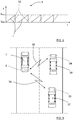
- Alignment to a communicating radar in the frequency domain for example for use in Radcom, i.e. data communication signals 38, 39 between radar systems 3; 34, 35 in different vehicles 1; 36, 37 as shown in Figure 6 , has previously been a challenge without having a separate channel for monitoring. Then, a transmission of FMCW chirp signals 4 had to take place when the communicating radar is pausing to avoid interference. While pausing the transmission, the receiver could listen to the communicating radar.
- the second receiver 21b power consumption, duty cycle, the ADC and the processing need not be optimized for radar only application. This means that components comprised in the second receiver 21b can be of relatively low cost and low performance compared to normal radar components.
- Radcom data communication signals 38, 39 can be received by means of the second receiver 21b, separately and independently of the radar waveform used.
- a control unit 33 comprised in the radar system 3 is adapted to change radar sub-band or center frequency of the chirp signal 4.
- FIG. 4 shows a second example of a chirp signal
- the control unit 33 is adapted to schedule the time gap 30 to correspond to the occurrence of interfering signals 31 to mitigate interference. This scheduling is enabled by means of the second receiver 21b that is adapted to monitoring the used frequency band.
- the control unit 33 is adapted to time the chirp signal 4 in such a way that that an interfering signal 32 occurs between adjacent ramps r to mitigate interference.
- the interfering signal 32 thus occurs between radar signal occurrences such that the radar signal 4 and the interfering signal 32 do not co-exist in time and frequency.
- This timing is enabled by means of the second receiver 21b that is adapted to monitoring the used frequency band.
- the relative drift in time and frequency between the chirp signal 4 and the interfering signal 32 caused by hardware tolerances can be continuously monitored. Dependent on the monitoring result, the mitigation methods and parameters could be adapted.
- the listen before talk method could be improved with the disclosure because the Radar RX and TX path could be configured in ready state and don't need to be reconfigured.
- the listen before talk approach generally means that a transmitter is configured without being switched on. For example, a pre-ramp can be analyzed in a receiver that is listening, and if the frequency band is used by someone else, there is no transmission, instead the transmission has to wait or another frequency band has to be chosen. The transmitter configuration is reset in case of band change. After listening again, the transmission can be started if the frequency band is not used by someone else.
- free slots in time and frequency are detected, continuously monitored, and the transmitter is configured accordingly before transmission.
- an independent receiving channel is obtained.
- This channel can according to some aspects be used to align a radar signal to communicating radars in the frequency domain and thus enabling data communication between different radar systems 3; 34, 35, track interfering radars and their timing and waveforms, monitor free sub bands of the radar band, and to find free timeslots by constant tracking or by using the channel for listen before talk without the costly processing and without demanding duty cycle.
- the present disclosure also relates to a method for a vehicle radar system 3, where the method comprises generating and transmitting S1 a radar signal 4 using a transmitter 20 with a transmitter oscillator 23, and receiving S2 reflected signals 5 using a first receiver 21a having a first receiver mixer, where the transmitted radar signals 4 have been reflected by an object 6.
- the method further comprises using S3 a second receiver 21b having a second receiver mixer 12b that is connected directly to an oscillator 23, 8.
- the second receiver mixer 12b is connected directly to a separate oscillator 8 in the second receiver 21b.
- the second receiver mixer 12b is connected directly to the transmitter oscillator 23.
- the method comprises scheduling S4 a time gap 30 in the transmitted radar signal 4 where the transmitter 20 is controlled to pause transmitting.
- method comprises timing S5 the radar signal 4 in such a way that that an interfering signal 32 occurs between radar signal occurrences.
- the method comprises aligning S6 the radar signal 4 to different communicating radar systems 3; 34, 35 and thus enabling data communication between these radar systems 3; 34, 35.
- the vehicle radar system 3 is used for transmitting and receiving frequency modulated continuous wave (FMCW) chirp signals, the radar signals 4 being constituted by an FMCW chirp signal 4.
- FMCW frequency modulated continuous wave
- any type of radar signals can be used, not only FMCW signals.
- Any type of communication between different radar systems 3; 34, 35 is possible, not being limited to the Radcom methods and systems previously known.
- the radar system 3 may comprise several radar transceivers, where one or more of these can comprise the second receiver according to the present disclosure.
- the radar system may be implemented in any type of vehicle such as cars, trucks and buses as well as boats and aircraft.
- the number of antenna arrangements, antennas within each antenna arrangement and IF signals may vary.
- each ADC arrangement and the DSP arrangement should each one be interpreted as having a corresponding ADC or DSP functionality, and may each be constituted by a plurality of separate components.
- each ADC arrangement may be comprised in one ADC chip, and each DSP arrangement may be comprised in one DSP chip.
- Each antenna arrangement 13a, 13b; 25 may for example comprise on or more antennas, and each antenna may be constituted by one antenna element or by an array of antenna elements.
- the first receiver antenna arrangement 13a and the second receiver antenna arrangement 13a can be constituted by one and the same common receiver antenna arrangement, where a power splitter and possibly a switch arrangement can be used for sharing the common receiver antenna arrangement between the first receiver 21a and the second receiver 21b.
- Each receiver and transmitter is to be regarding as a corresponding receiver arrangement and transmitter arrangement, having a corresponding functionality.
- a transmitter arrangement 20 a first receiver arrangement 21a and a second receiver arrangement 21b.
- the transceiver 10 can comprise two or more monitoring receivers of the same kind as the second receiver 21b described.
- the second ADC and DSP arrangement 18b is not necessary, and instead there can be any suitable detector device that is that is adapted for detecting the received digital signals.
- the present disclosure relates to a vehicle radar system 3 comprising a control unit 33 and a transceiver arrangement 10 that comprises a transmitter arrangement 20.
- the transmitter arrangement 20 comprises a transmitter oscillator 23, a signal generator 24 and a transmit antenna arrangement 25, where the transmitter arrangement 20 is arranged to generate and transmit a radar signal 4.
- the vehicle radar system 3 further comprises a first receiver arrangement 21a that comprises a first receiver mixer 12b, where the first receiver arrangement 21a is arranged to receive reflected signals 5 where the transmitted radar signals 4 have been reflected by an object 6.
- the transceiver arrangement 10 comprises a second receiver arrangement 21b that in turn comprises a second receiver mixer 12b, where the second receiver mixer 12b is connected directly to an oscillator 23, 8.
- the second receiver mixer 12b is connected directly to a separate oscillator 8 that is comprised in the second receiver arrangement 21b.
- the second receiver mixer 12b is connected directly to the transmitter oscillator 23.
- control unit 33 is adapted to schedule a time gap 30 in the transmitted radar signal 4 where the transmitter arrangement 20 is controlled to pause transmitting.
- control unit 33 is adapted to time the radar signal 4 in such a way that that an interfering signal 32 occurs between radar signal occurrences.
- control unit 33 is adapted to align the radar signal 4 to different communicating radar systems 3; 34, 35 and thus enabling data communication between these radar systems 3; 34, 35.
- the radar system 3 is adapted for transmitting and receiving frequency modulated continuous wave (FMCW) chirp signals, the radar signal 4 being constituted by an FMCW chirp signal 4.
- FMCW frequency modulated continuous wave
- the present disclosure also relates to a vehicle 1 comprising the vehicle radar system 3 according to the above.
Landscapes
- Engineering & Computer Science (AREA)
- Radar, Positioning & Navigation (AREA)
- Remote Sensing (AREA)
- Computer Networks & Wireless Communication (AREA)
- Physics & Mathematics (AREA)
- General Physics & Mathematics (AREA)
- Electromagnetism (AREA)
- Radar Systems Or Details Thereof (AREA)
Priority Applications (1)
| Application Number | Priority Date | Filing Date | Title |
|---|---|---|---|
| EP19213811.3A EP3832350A1 (de) | 2019-12-05 | 2019-12-05 | Fahrzeugradarsystem mit überwachungsfunktion |
Applications Claiming Priority (1)
| Application Number | Priority Date | Filing Date | Title |
|---|---|---|---|
| EP19213811.3A EP3832350A1 (de) | 2019-12-05 | 2019-12-05 | Fahrzeugradarsystem mit überwachungsfunktion |
Publications (1)
| Publication Number | Publication Date |
|---|---|
| EP3832350A1 true EP3832350A1 (de) | 2021-06-09 |
Family
ID=68806660
Family Applications (1)
| Application Number | Title | Priority Date | Filing Date |
|---|---|---|---|
| EP19213811.3A Pending EP3832350A1 (de) | 2019-12-05 | 2019-12-05 | Fahrzeugradarsystem mit überwachungsfunktion |
Country Status (1)
| Country | Link |
|---|---|
| EP (1) | EP3832350A1 (de) |
Cited By (5)
| Publication number | Priority date | Publication date | Assignee | Title |
|---|---|---|---|---|
| FR3132406A1 (fr) * | 2022-01-31 | 2023-08-04 | Psa Automobiles Sa | Procédé et dispositif de communication pour véhicule utilisant des radars |
| EP4290268A1 (de) * | 2022-06-07 | 2023-12-13 | Honeywell International Inc. | Systeme und verfahren zur verringerung von telekommunikationssignalstörungen bei radarhöhenmessern |
| US20250199112A1 (en) * | 2023-12-19 | 2025-06-19 | Nxp B.V. | Interference sensing and adaptation |
| EP4405705A4 (de) * | 2021-09-23 | 2025-07-09 | Intel Corp | Vorrichtung, system und verfahren zur planung von radarübertragungen |
| WO2026008782A1 (fr) * | 2024-07-04 | 2026-01-08 | Aumovio Germany Gmbh | Dispositif de détection d'une personne dans au moins une zone predeterminee autour d'un vehicule automobile |
Citations (5)
| Publication number | Priority date | Publication date | Assignee | Title |
|---|---|---|---|---|
| DE102009054776A1 (de) * | 2009-01-23 | 2010-08-12 | Adc Automotive Distance Control Systems Gmbh | Kommunikation über Radar |
| US20160320481A1 (en) * | 2015-05-01 | 2016-11-03 | Maxlinear, Inc. | Multistatic Radar Via an Array of Multifunctional Automotive Transceivers |
| CN106772336A (zh) * | 2017-02-28 | 2017-05-31 | 西安电子科技大学 | 雷达探测与通信检测一体化的系统及实现方法 |
| US20190056476A1 (en) * | 2017-08-18 | 2019-02-21 | Nxp B.V. | Radar unit, integrated circuit and methods for detecting and mitigating mutual interference |
| WO2019106656A1 (en) * | 2017-11-29 | 2019-06-06 | Arbe Robotics Ltd. | Detection, mitigation and avoidance of mutual interference between automotive radars |
-
2019
- 2019-12-05 EP EP19213811.3A patent/EP3832350A1/de active Pending
Patent Citations (5)
| Publication number | Priority date | Publication date | Assignee | Title |
|---|---|---|---|---|
| DE102009054776A1 (de) * | 2009-01-23 | 2010-08-12 | Adc Automotive Distance Control Systems Gmbh | Kommunikation über Radar |
| US20160320481A1 (en) * | 2015-05-01 | 2016-11-03 | Maxlinear, Inc. | Multistatic Radar Via an Array of Multifunctional Automotive Transceivers |
| CN106772336A (zh) * | 2017-02-28 | 2017-05-31 | 西安电子科技大学 | 雷达探测与通信检测一体化的系统及实现方法 |
| US20190056476A1 (en) * | 2017-08-18 | 2019-02-21 | Nxp B.V. | Radar unit, integrated circuit and methods for detecting and mitigating mutual interference |
| WO2019106656A1 (en) * | 2017-11-29 | 2019-06-06 | Arbe Robotics Ltd. | Detection, mitigation and avoidance of mutual interference between automotive radars |
Non-Patent Citations (2)
| Title |
|---|
| DEBORAH COHEN ET AL: "Spectrum Sharing Radar: Coexistence via Xampling", ARXIV.ORG, CORNELL UNIVERSITY LIBRARY, 201 OLIN LIBRARY CORNELL UNIVERSITY ITHACA, NY 14853, 19 November 2016 (2016-11-19), XP080733282, DOI: 10.1109/TAES.2017.2780599 * |
| HUANG YIXUAN ET AL: "NC-OFDM RadCom system for electromagnetic spectrum interference", 2017 IEEE 17TH INTERNATIONAL CONFERENCE ON COMMUNICATION TECHNOLOGY (ICCT), IEEE, 27 October 2017 (2017-10-27), pages 877 - 881, XP033340024, [retrieved on 20180515], DOI: 10.1109/ICCT.2017.8359760 * |
Cited By (7)
| Publication number | Priority date | Publication date | Assignee | Title |
|---|---|---|---|---|
| EP4405705A4 (de) * | 2021-09-23 | 2025-07-09 | Intel Corp | Vorrichtung, system und verfahren zur planung von radarübertragungen |
| FR3132406A1 (fr) * | 2022-01-31 | 2023-08-04 | Psa Automobiles Sa | Procédé et dispositif de communication pour véhicule utilisant des radars |
| EP4290268A1 (de) * | 2022-06-07 | 2023-12-13 | Honeywell International Inc. | Systeme und verfahren zur verringerung von telekommunikationssignalstörungen bei radarhöhenmessern |
| US12468011B2 (en) | 2022-06-07 | 2025-11-11 | Honeywell International Inc. | Systems and methods for mitigating telecommunications signal interference to radar altimeters |
| US20250199112A1 (en) * | 2023-12-19 | 2025-06-19 | Nxp B.V. | Interference sensing and adaptation |
| WO2026008782A1 (fr) * | 2024-07-04 | 2026-01-08 | Aumovio Germany Gmbh | Dispositif de détection d'une personne dans au moins une zone predeterminee autour d'un vehicule automobile |
| FR3164291A1 (fr) * | 2024-07-04 | 2026-01-09 | Continental Automotive Technologies GmbH | Dispositif de détection d’une personne dans au moins une zone prédéterminée autour d’un véhicule automobile |
Similar Documents
| Publication | Publication Date | Title |
|---|---|---|
| EP3832350A1 (de) | Fahrzeugradarsystem mit überwachungsfunktion | |
| US11215692B2 (en) | FMCW radar with additional AM for interference detection | |
| EP3056920B1 (de) | Kraftfahrzeugradarsystem mit zwei Sender-Empfänger-Anordnungen | |
| EP2876460B1 (de) | Fahrzeugradar mit zwei Senderantennenanordnungen | |
| US11789114B2 (en) | FMCW radar with frequency hopping | |
| US11914069B2 (en) | System and MMIC architecture for coherent multi-chip phased array MIMO applications | |
| KR101137088B1 (ko) | 통합 레이더 장치 및 통합 안테나 장치 | |
| EP3306339A1 (de) | Zur verringerung von interferenzen angeordnetes fahrzeugradarsystem | |
| EP3147685B1 (de) | Fahrzeugradarsystem mit synthetischer apertur | |
| AU2005242826B2 (en) | System and method for concurrent operation of multiple radar or active sonar systems on a common frequency | |
| US7791530B2 (en) | Time duplex apparatus and method for radar sensor front-ends | |
| US8947293B2 (en) | Radar apparatus | |
| JP5382087B2 (ja) | レーダ装置 | |
| US8305256B1 (en) | Radar with PRF alteration on receive | |
| EP3324201B1 (de) | Fahrzeugradarsystemwellenform | |
| EP2584373B1 (de) | Radarvorrichtung | |
| US11899125B2 (en) | Automatic interference detection and avoidance in radar transceiver systems | |
| US20110163906A1 (en) | Radar apparatus, antenna apparatus, and data acquisition method | |
| US20180284267A1 (en) | A modular vehicle radar | |
| US11977180B2 (en) | Radar system with monitoring function | |
| KR101167906B1 (ko) | 차량용 레이더시스템 및 차량용 레이더 시스템의 표적탐지 방법 | |
| EP1933164B1 (de) | Radargerät und verfahren zur inter-radarortseinstellung | |
| US20140313068A1 (en) | Apparatus and a method for obtaining information about at least one target | |
| KR101007216B1 (ko) | 장거리 탐지용 레이더 장치 | |
| EP2901174B1 (de) | Frequenzmoduliertes kontinuierliches wellenformradar (fmcw) |
Legal Events
| Date | Code | Title | Description |
|---|---|---|---|
| PUAI | Public reference made under article 153(3) epc to a published international application that has entered the european phase |
Free format text: ORIGINAL CODE: 0009012 |
|
| STAA | Information on the status of an ep patent application or granted ep patent |
Free format text: STATUS: THE APPLICATION HAS BEEN PUBLISHED |
|
| AK | Designated contracting states |
Kind code of ref document: A1 Designated state(s): AL AT BE BG CH CY CZ DE DK EE ES FI FR GB GR HR HU IE IS IT LI LT LU LV MC MK MT NL NO PL PT RO RS SE SI SK SM TR |
|
| STAA | Information on the status of an ep patent application or granted ep patent |
Free format text: STATUS: REQUEST FOR EXAMINATION WAS MADE |
|
| 17P | Request for examination filed |
Effective date: 20211203 |
|
| RBV | Designated contracting states (corrected) |
Designated state(s): AL AT BE BG CH CY CZ DE DK EE ES FI FR GB GR HR HU IE IS IT LI LT LU LV MC MK MT NL NO PL PT RO RS SE SI SK SM TR |
|
| STAA | Information on the status of an ep patent application or granted ep patent |
Free format text: STATUS: EXAMINATION IS IN PROGRESS |
|
| 17Q | First examination report despatched |
Effective date: 20230125 |
|
| RAP3 | Party data changed (applicant data changed or rights of an application transferred) |
Owner name: MAGNA ELECTRONICS SWEDEN AB |
|
| RAP3 | Party data changed (applicant data changed or rights of an application transferred) |
Owner name: MAGNA ELECTRONICS SWEDEN AB |