EP3832363B1 - Dispositif et procédé de connexion d'une préforme de fibre sur un système d'alimentation en pression - Google Patents
Dispositif et procédé de connexion d'une préforme de fibre sur un système d'alimentation en pression Download PDFInfo
- Publication number
- EP3832363B1 EP3832363B1 EP19213094.6A EP19213094A EP3832363B1 EP 3832363 B1 EP3832363 B1 EP 3832363B1 EP 19213094 A EP19213094 A EP 19213094A EP 3832363 B1 EP3832363 B1 EP 3832363B1
- Authority
- EP
- European Patent Office
- Prior art keywords
- fibre preform
- ssp
- fsp
- elongate holes
- ports
- Prior art date
- Legal status (The legal status is an assumption and is not a legal conclusion. Google has not performed a legal analysis and makes no representation as to the accuracy of the status listed.)
- Active
Links
Images
Classifications
-
- G—PHYSICS
- G02—OPTICS
- G02B—OPTICAL ELEMENTS, SYSTEMS OR APPARATUS
- G02B6/00—Light guides; Structural details of arrangements comprising light guides and other optical elements, e.g. couplings
- G02B6/02—Optical fibres with cladding with or without a coating
- G02B6/02295—Microstructured optical fibre
- G02B6/02314—Plurality of longitudinal structures extending along optical fibre axis, e.g. holes
- G02B6/02319—Plurality of longitudinal structures extending along optical fibre axis, e.g. holes characterised by core or core-cladding interface features
- G02B6/02323—Core having lower refractive index than cladding, e.g. photonic band gap guiding
- G02B6/02328—Hollow or gas filled core
-
- C—CHEMISTRY; METALLURGY
- C03—GLASS; MINERAL OR SLAG WOOL
- C03B—MANUFACTURE, SHAPING, OR SUPPLEMENTARY PROCESSES
- C03B37/00—Manufacture or treatment of flakes, fibres, or filaments from softened glass, minerals, or slags
- C03B37/01—Manufacture of glass fibres or filaments
- C03B37/02—Manufacture of glass fibres or filaments by drawing or extruding, e.g. direct drawing of molten glass from nozzles; Cooling fins therefor
- C03B37/025—Manufacture of glass fibres or filaments by drawing or extruding, e.g. direct drawing of molten glass from nozzles; Cooling fins therefor from reheated softened tubes, rods, fibres or filaments, e.g. drawing fibres from preforms
- C03B37/027—Fibres composed of different sorts of glass, e.g. glass optical fibres
- C03B37/02736—Means for supporting, rotating or feeding the tubes, rods, fibres or filaments to be drawn, e.g. fibre draw towers, preform alignment, butt-joining preforms or dummy parts during feeding
-
- C—CHEMISTRY; METALLURGY
- C03—GLASS; MINERAL OR SLAG WOOL
- C03B—MANUFACTURE, SHAPING, OR SUPPLEMENTARY PROCESSES
- C03B37/00—Manufacture or treatment of flakes, fibres, or filaments from softened glass, minerals, or slags
- C03B37/01—Manufacture of glass fibres or filaments
- C03B37/02—Manufacture of glass fibres or filaments by drawing or extruding, e.g. direct drawing of molten glass from nozzles; Cooling fins therefor
- C03B37/025—Manufacture of glass fibres or filaments by drawing or extruding, e.g. direct drawing of molten glass from nozzles; Cooling fins therefor from reheated softened tubes, rods, fibres or filaments, e.g. drawing fibres from preforms
- C03B37/027—Fibres composed of different sorts of glass, e.g. glass optical fibres
- C03B37/02781—Hollow fibres, e.g. holey fibres
-
- C—CHEMISTRY; METALLURGY
- C03—GLASS; MINERAL OR SLAG WOOL
- C03B—MANUFACTURE, SHAPING, OR SUPPLEMENTARY PROCESSES
- C03B2203/00—Fibre product details, e.g. structure, shape
- C03B2203/10—Internal structure or shape details
- C03B2203/14—Non-solid, i.e. hollow products, e.g. hollow clad or with core-clad interface
- C03B2203/16—Hollow core
-
- C—CHEMISTRY; METALLURGY
- C03—GLASS; MINERAL OR SLAG WOOL
- C03B—MANUFACTURE, SHAPING, OR SUPPLEMENTARY PROCESSES
- C03B2203/00—Fibre product details, e.g. structure, shape
- C03B2203/42—Photonic crystal fibres, e.g. fibres using the photonic bandgap PBG effect, microstructured or holey optical fibres
Definitions
- the present invention relates to a device and method for connecting a fibre preform including a plurality of elongate holes extending substantially parallel to a longitudinal axis of the fibre preform to a pressure supply system.
- Solid-core fibres are generally known and broadly used e.g. in data communication applications.
- Solid-core fibres can be designed for low-loss, single-mode transmission in a broadband transmission range of the fibre material, like quartz glass.
- So-called endlessly single-mode guidance (ESM, i.e. all higher order modes, HOMs, are leaky while the fundamental LP 01 mode is fully confined) is achieved in solid-core photonic crystal fibres (PCFs) by engineering a cladding structure surrounding the solid-core, as shown in Figure 1A (prior art), such that the diameter d of channels in the cladding structure and their centre-centre spacing (pitch) ⁇ fulfils the geometrical condition d/ ⁇ ⁇ 0.41.
- Pitch centre-centre spacing
- HC-PCFs Through their ability to guide light in a non-solid core region, which is evacuated (vacuum core), filled with a gas or filled with a liquid, hollow-core photonic crystal fibres, HC-PCFs, have unique advantages compared to solid-core fibres, resulting in application areas such as low-latency data transmission, high-power beam delivery, gas-based nonlinear optics, light guiding with ultralow nonlinearities and chemical sensing.
- HC-PCFs are typically divided into two classes depending on the physical guidance mechanism: hollow-core photonic bandgap fibres (HC-PBFs) and hollow-core anti-resonant-reflecting fibres (HC-AFs).
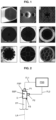
- Figures 1B to 1I shows a selection of scanning electron micrographs of different types of conventional HC- PCFs.
- Figures 1B and 1C show HC-PBFs that confine modes inside a central hollow core by means of a photonic bandgap in the cladding.
- These types of PCF typically have relatively low loss (ca. ⁇ 20 dB/km) at telecommunication wavelengths.
- due to the wavelength-specific effect of the photonic bandgap they guide light over a relatively narrow bandwidth (ca. ⁇ 15 THz) only.
- HC-PBFs support HOMs
- bended HC-PBFs can be made effectively single-mode by including "satellite" hollow cores in the cladding ( Fig. 1B ). These satellites strongly suppress HOMs in the core by phase-matching to them, causing high HOM loss.
- HC-PBGs can also be made truly single-mode over a narrow spectral range (ca. ⁇ 7 THz) if a small enough core is used
- Figures 1D to 1I show a selection of HC-AF structures, i.e. fibres having guidance mechanism based mostly on anti-resonant effects.
- Figures 1D and 1E have a Kagomé-lattice cladding and
- Figures 1F and 1G have one ring of single (F) or nested (G) anti-resonant elements (AREs).
- Figure 1H shows a HC-AF with a square core and
- Fig. 1I depicts a HC-AF with guiding properties in the ultraviolet.
- the loss of HC-AFs is in general larger because of the non-ideal confinement, but the transmission window is broader.
- HC-PCFs are typically fabricated from glass preforms in a fibre drawing process.
- the transverse structure of these preforms resembles that of the final fibre material, i.e. a plurality of elongate holes extending substantially parallel to a longitudinal axis of the fibre preform in a well-defined pattern.
- the transverse structure is scaled down from the original preform diameter, typically a few millimetres, to the diameter of the optical fibre, typically 100 to 500 micrometres.
- a drawback of the current drawing process is that connecting plurality of elongate holes to a pressure supply system is a complicated and time intensive process
- a device for connecting a fibre preform including a plurality of elongate holes extending substantially parallel to a longitudinal axis of the fibre preform to a pressure supply system comprising:
- the second surface includes a first surface portion substantially opposite the first surface and a second surface portion extending substantially non-parallel to the first surface, and wherein at least one port is arranged at the first surface portion of the second surface and at least one other port is arranged at the second surface portion of the second surface. This may provide more space between the at least two ports as the ports are arranged at surface portions that extend in different directions and thus have a different orientation.
- the end face of the fibre preform has a circular shape with a centre and a radius
- the device has a longitudinal axis to coincide with the centre of the fibre preform
- the second surface includes a first surface portion substantially opposite the first surface and a second surface portion extending substantially perpendicular to the first surface, and wherein at least one port is arranged at the second surface portion of the second surface at a distance from the longitudinal axis of the device that is larger than the radius of the fibre preform.
- the fibre preform typically has a radius in the range of a few millimetres.
- the device has a cylindrical shape with the first surface being an end surface of the cylindrical shape, wherein the second surface includes a first surface portion being an end surface of the cylindrical shape opposite the first surface and a second surface portion being a side surface of the cylindrical shape.
- the cylindrical shape corresponds to a right circular cylinder or a right elliptic cylinder.
- the first surface is provided with one or more nozzles to mate with corresponding tubular elements in the fibre preform forming elongate holes.
- An advantage of nozzles may be that sealing between an elongate hole and the channel system is improved and/or that the mechanical robustness is improved and/or that the alignment process between first surface of the device and the end face of the fibre preform is simplified.
- the channel system at a distance from the first surface occupies a cross-sectional area that is larger than a cross-sectional area occupied by the channel system at the first surface.
- Such a diverging channel system allows to easily create additional space for connecting the at least two ports to the pressure supply system.
- the intermediate device portion has one or more of the following features:
- the above mentioned feature a allows for an easy to fabricate port at a side surface of the device by incorporating the port in an intermediate device portion.
- a port may for instance be fabricated as an opening extending over the entire height of the intermediate device that is delimited at the bottom and top side by the adjacent device portions.
- the above mentioned feature c. allows channels that need to be pressurized with the same pressure to be combined to reduce the number of ports necessary to connect the fibre preform to the pressure supply system.
- the above mentioned feature d. allows for instance to increase the cross-section of the channels to match the size of a port or connection to the pressure supply system.
- the top device portion includes a port arranged at a side surface of the top device portion and/or a port arranged at a surface facing away from the at least one intermediate device portion.
- a method for connecting a fibre preform including a plurality of elongate holes extending substantially parallel to a longitudinal axis of the fibre preform to a pressure supply system comprising the following steps:
- the end face of the fibre preform is attached to the first surface of the device using a sealant to provide a substantially gas-tight connection between elongate holes in the fibre preform and the channel system of the device.
- the method comprises the following steps:
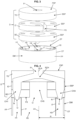
- Fig. 2 schematically depicts a fibre preform FP including a plurality of elongate holes extending substantially parallel to a longitudinal axis LA for instance similar to any of the shown examples B-I in Fig. 1 .
- the plurality of elongate holes end at an end face of the preform FP as for instance shown in Fig. 1 for the examples B-I.
- Fig. 2 schematically depicts how the fibre preform FP is connected to a pressure supply system PSS.
- a device D is provided according to the invention, examples of which will be explained below in more detail.
- the device D includes a first surface FS connected to an end face of the fibre preform FP where the plurality of elongate holes end, and a second surface including a first surface portion FSP substantially opposite the first surface FS and a second surface portion SSP extending between the first surface FS and the first surface portion FSP.
- first port P1 connected to the pressure supply system PSS via a first fluid communication line FL1.
- second port P2 is arranged to the pressure supply system PSS via a second fluid communication line FL2.
- At least one of the plurality of elongate holes of the fibre preform FP is connected to the first port P1 while at least one other of the plurality of elongate holes is connected to the second port P2 via channel system within the device D examples of which will be explained below in more detail.
- channel system the two ports P1, P2 and the two fluid communication lines FL1, FL2, it is possible to use the pressure supply system to provide different pressures to different elongate holes.
- the density of the two ports P1, P2 at the second surface is smaller than a corresponding density of the channel system at the first surface as will be explained below in more detail.
- Figs. 3 and 4 schematically depict an exploded view and a cross-sectional view of a device D according to an embodiment of the invention and a fibre preform FP, respectively.
- the fibre preform FP is schematically depicted as an outer tube OT encompassing four smaller inner tubes IT.
- the preform FP includes five elongate holes H1-H5, namely four elongate holes H1-H4 corresponding to the four inner tubes IT, respectively, and the elongate hole H5 corresponding to the space inside the outer tube OT in between the four inner tubes IT.
- the fibre preform FP has a cylindrical shape, at least near the device D, defined by a side wall SW of the outer tube OT and delimited at one end by an end face EF, which end face EF is also a face where the elongate holes H1-H5 end.
- the end face EF thus has a circular shape with a centre coinciding with a longitudinal axis LA of the preform FP and a radius R.
- the device D includes a bottom device portion BD, an intermediate device portion ID, and a top device portion TD.
- the device D has a cylindrical shape with a longitudinal axis DLA, so that the device portions BD, ID, TD form cylindrically shaped segments stacked upon each other to form the device D.
- the bottom device portion BD includes a first surface FS connected to the end face EF of the fibre preform FP, e.g. using a sealant to provide a substantially gas-tight connection.
- the top device portion TD includes a first surface portion FSP opposite to the first surface FS, which first surface portion FSP is part of a second surface of the device D.
- the device portions BD, ID, TD all include a portion of a second surface portion SSP extending between the first surface SP at the bottom device portion BD and the first surface portion FSP and being part of the second surface of the device D.
- the first surface FS of the device D includes an opening O per elongate hole H1-H5, which five openings O are connected to the first port P1 or the second port P2 via five corresponding channels of a channel system of which only the channels CH1, CH3 and CH5 are visible in Fig. 4 .
- a distance between the first port P1 and the second port P2 at the second surface of the device D can be larger than a distance between the openings O at the first surface FS of the device D.
- space is created to connect the first and second ports P1, P2 to a pressure supply system.
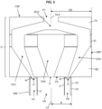
- Fig. 5 depicts a cross-sectional view of a device D according to another embodiment of the invention connected to the same fibre preform FP as in the embodiment of Figs. 3 and 4 .
- similar reference symbols are used to indicate similar parts of the device D and the description below focuses on the differences between the two embodiments, so that the description relating to the embodiment of Figs. 3 and 4 also applies to the embodiment of Fig. 5 as well for the similarities.
- the device D in Fig. 5 has a cylindrical shape with a radius DR that is larger than the radius R of the fibre preform FP.
- more surface area at the second surface of the device D is available for ports, such as the first port P1 and the second port P2, allowing to increase the number of ports while substantially keeping the same density of ports or to increase the size of the ports or use larger connectors to connect the ports to the pressure supply system.
- the openings O of the channel system are arranged around a centre of the first surface FS and do not cover the entire first surface FS.
- the channels CH1-CH5 of the channel system in the bottom device portion BD can diverge towards the intermediate device portion ID and/or taper outwards towards the intermediate device portion ID, so that a size of a cross-section of the one or more channels CH1-CH5 increases towards a top device portion side of the bottom device portion BD.
- the intermediate device portion ID and the top device portion TD have a similar construction compared to the embodiment of Figs. 3 and 4 , but with increased dimensions.
- the device D is modular and being made of a plurality of device portions, it is possible to use a single component device D as well. Such a device D can for instance be manufactured using 3D printing techniques.
Landscapes
- Chemical & Material Sciences (AREA)
- Engineering & Computer Science (AREA)
- Materials Engineering (AREA)
- Geochemistry & Mineralogy (AREA)
- Manufacturing & Machinery (AREA)
- General Life Sciences & Earth Sciences (AREA)
- Life Sciences & Earth Sciences (AREA)
- Organic Chemistry (AREA)
- Physics & Mathematics (AREA)
- General Physics & Mathematics (AREA)
- Optics & Photonics (AREA)
- Optical Fibers, Optical Fiber Cores, And Optical Fiber Bundles (AREA)
- Electrical Discharge Machining, Electrochemical Machining, And Combined Machining (AREA)
- Moulding By Coating Moulds (AREA)
- Filling Or Discharging Of Gas Storage Vessels (AREA)
Claims (13)
- Un dispositif (D) pour le raccordement d'une préforme de fibre (FP) incluant une pluralité de trous allongés (H1, H2, H3, H4, H5) s'étendant de manière substantiellement parallèle à un axe longitudinal (LA) de la préforme de fibre (FP) à un système d'alimentation en pression (PSS), ledit dispositif (D) comprenant :a. une première surface (FS) à raccorder à une face d'extrémité (EF) de la préforme de fibre (FP) où finissent la pluralité de trous allongés (H1, H2, H3, H4, H5) ;b. une deuxième surface (FSP, SSP) comprenant au moins deux orifices (P1, P2) configurée afin d'être en raccordement fluidique avec le système d'alimentation en pression (PSS) ; etc. un système de canaux (CH1, CH3, CH5) au sein du dispositif (D) raccordant la pluralité de trous allongés (H1, H2, H3, H4, H5) au niveau de la première surface (FS) aux au moins deux orifices (P1, P2) de telle sorte qu'au moins un trou de la pluralité de trous allongés (H1, H2, H3, H4, H5) est raccordé à l'un des au moins deux orifices (P1, P2) et de telle sorte qu'au moins un autre trou de la pluralité de trous allongés (H1, H2, H3, H4, H5) est raccordé à un autre des au moins deux orifices (P1, P2),où une densité des au moins deux orifices (P1, P2) au niveau de la deuxième surface (FSP, SSP) est plus petite qu'une densité correspondante du système de canaux (CH1, CH3, CH5) au niveau de la première surface (FS),où le dispositif (D) comprend une portion de dispositif de dessous (BD), une portion de dispositif intermédiaire (ID) et une portion de dispositif de dessus (TD), et où le dispositif (D) a une forme cylindrique avec un axe longitudinal (DLA) de sorte que la portion de dispositif de dessous (BD), la portion de dispositif intermédiaire (ID) et la portion de dispositif de dessus (TD) constituent des segments de forme cylindrique empilés les uns sur les autres afin de constituer le dispositif (D).
- Un dispositif selon la revendication 1, où la deuxième surface (FSP, SSP) inclut une première portion de surface (FSP) substantiellement à l'opposé de la première surface (FS) et une deuxième portion de surface (SSP) s'étendant de manière substantiellement non parallèle à la première surface (FS), et où au moins un orifice est agencé au niveau de la première portion de surface (FSP) de la deuxième surface (FSP, SSP) et au moins un autre orifice est agencé au niveau de la deuxième portion de surface (SSP) de la deuxième surface (FSP, SSP).
- Un dispositif (D) selon la revendication 1 ou la revendication 2, où la face d'extrémité (EF) de la préforme de fibre (FP) a une forme circulaire avec un centre et un rayon (R), où le dispositif (D) a l'axe longitudinal (DLA) afin qu'il coïncide avec le centre de la préforme de fibre (FP), où la deuxième surface (FSP, SSP) inclut la première portion de surface (FSP) substantiellement à l'opposé de la première surface (FS) et la deuxième portion de surface (SSP) s'étendant de manière substantiellement perpendiculaire à la première surface (FS), et où au moins un orifice (P1, P2) est agencé au niveau de la deuxième portion de surface (SSP) de la deuxième surface (FSP, SSP) à une distance de l'axe longitudinal (LA) du dispositif (D) qui est plus grande que le rayon (R) de la préforme de fibre (FP).
- Un dispositif (D) selon n'importe lesquelles des revendications 1 à 3, où le dispositif (D) a la forme cylindrique avec la première surface (FS) qui est une surface d'extrémité de la forme cylindrique, où la deuxième surface (FSP, SSP) inclut une première portion de surface (FSP) qui est une surface d'extrémité de la forme cylindrique à l'opposé de la première surface (FS) et une deuxième portion de surface (SSP) qui est une surface de côté de la forme cylindrique.
- Un dispositif (D) selon la revendication 4, où la forme cylindrique correspond à un cylindre circulaire droit ou un cylindre elliptique droit.
- Un dispositif (D) selon n'importe lesquelles des revendications 1 à 5, où la première surface (FS) est pourvue d'une ou de plusieurs tuyères (N) afin qu'elles s'accouplent avec des éléments tubulaires (IT) correspondants dans la préforme de fibre (FP) constituant les trous allongés (H1, H2, H3, H4, H5).
- Un dispositif (D) selon n'importe lesquelles des revendications 1 à 6, où le système de canaux (CH1, CH3, CH5) à une distance de la première surface (FS) occupe une aire de section transversale qui est plus grande qu'une aire de section transversale occupée par le système de canaux (CH1, CH3, CH5) au niveau de la première surface (FS).
- Un dispositif (D) selon la revendication 1, où la portion de dispositif intermédiaire (ID) a une ou plusieurs des caractéristiques suivantes :a. un orifice (P2) au niveau d'une surface de côté de la portion de dispositif intermédiaire (ID) ;b. un ou plusieurs canaux non ramifiés s'étendant à travers la portion de dispositif intermédiaire (ID) ;c. des canaux qui sont combinés en un canal unique ;d. un ou plusieurs canaux qui sont effilés, par ex. de telle sorte qu'une dimension d'une section transversale des un ou plusieurs canaux croît en direction d'un côté vers la portion de dispositif de dessus (TD) de la portion de dispositif intermédiaire (ID) ;et où la portion de dispositif de dessous (BD) inclut la première surface (FS).
- Un dispositif (D) selon la revendication 8, où la portion de dispositif de dessus (TD) inclut un orifice (P2) agencé au niveau d'une surface de côté de la portion de dispositif de dessus (TD) et/ou un orifice (P1) agencé au niveau d'une surface tournée du côté opposé à l'au moins une portion de dispositif intermédiaire (ID).
- Un procédé pour le raccordement d'une préforme de fibre (FP) incluant une pluralité de trous allongés (H1, H2, H3, H4, H5) s'étendant de manière substantiellement parallèle à un axe longitudinal (LA) de la préforme de fibre (FP) à un système d'alimentation en pression (PSS), ledit procédé comprenant les étapes suivantes :a. attacher une face d'extrémité (EF) de la préforme de fibre (FP) où finissent la pluralité de trous allongés (H1, H2, H3, H4, H5) à une première surface (FS) d'un dispositif (D) selon n'importe lesquelles des revendications 1 à 9 ; etb. raccorder les au moins deux orifices (P1, P2) au système d'alimentation en pression (PSS).
- Un procédé selon la revendication 10, où la face d'extrémité (EF) de la préforme de fibre (FP) est attachée à la première surface (FS) du dispositif (D) à l'aide d'un élément de scellage afin de fournir un raccord substantiellement étanche aux gaz entre des trous allongés (H1, H2, H3, H4, H5) dans la préforme de fibre (FP) et le système de canaux (CH1, CH3, CH5) du dispositif (D).
- Un procédé selon la revendication 10 ou la revendication 11, où le procédé comprend les étapes suivantes :i. préalablement à l'étape a., insérer un organe de blocage temporaire dans un ou plusieurs trous allongés (H1, H2, H3, H4, H5) dans la préforme de fibre (FP), l'organe de blocage temporaire étant configuré afin d'empêcher le blocage d'un passage entre le trou allongé (H1, H2, H3, H4, H5) correspondant et le système de canaux (CH1, CH3, CH5) du dispositif (D) durant l'étape a. ; etii. durant ou après l'étape a., enlever l'organe de blocage temporaire.
- Un procédé selon la revendication 12, où le dispositif (D) est un dispositif (D) selon n'importe lesquelles des revendications 1 à 9, où l'étape a. inclut l'étape d'attacher la face d'extrémité (EF) de la préforme de fibre (PF) à une portion de dispositif (BD) incluant la première surface (FS), et où l'étape ii. est effectuée à travers ladite portion de dispositif (BD) incluant la première surface (FS) et avant que d'autres portions de dispositif (TD, ID) ne soient raccordées à ladite portion de dispositif (BD) incluant la première surface (FS).
Priority Applications (8)
| Application Number | Priority Date | Filing Date | Title |
|---|---|---|---|
| DK19213094.6T DK3832363T3 (da) | 2019-12-03 | 2019-12-03 | En enhed og metode til at forbinde en fiberpræform til et trykforsyningssystem |
| EP19213094.6A EP3832363B1 (fr) | 2019-12-03 | 2019-12-03 | Dispositif et procédé de connexion d'une préforme de fibre sur un système d'alimentation en pression |
| CN202080083022.2A CN114787673B (zh) | 2019-12-03 | 2020-11-04 | 用于将光纤预制件连接至压力供应系统的装置和方法 |
| IL293395A IL293395B1 (en) | 2019-12-03 | 2020-11-04 | Apparatus and method for connecting a fiber enhancer to a pressure supply system |
| PCT/EP2020/080861 WO2021110338A1 (fr) | 2019-12-03 | 2020-11-04 | Dispositif et procédé de raccordement d'une préforme fibreuse à un système d'alimentation en pression |
| EP20205580.2A EP3832364A1 (fr) | 2019-12-03 | 2020-11-04 | Dispositif et procédé de connexion d'une préforme de fibre sur un système d'alimentation en pression |
| US17/096,278 US11780763B2 (en) | 2019-12-03 | 2020-11-12 | Device and method for connecting a fiber preform to a pressure supply system |
| TW109140022A TWI767413B (zh) | 2019-12-03 | 2020-11-17 | 用於將光纖預成型件連接至壓力供應系統之裝置及方法 |
Applications Claiming Priority (1)
| Application Number | Priority Date | Filing Date | Title |
|---|---|---|---|
| EP19213094.6A EP3832363B1 (fr) | 2019-12-03 | 2019-12-03 | Dispositif et procédé de connexion d'une préforme de fibre sur un système d'alimentation en pression |
Publications (2)
| Publication Number | Publication Date |
|---|---|
| EP3832363A1 EP3832363A1 (fr) | 2021-06-09 |
| EP3832363B1 true EP3832363B1 (fr) | 2025-01-29 |
Family
ID=68766564
Family Applications (2)
| Application Number | Title | Priority Date | Filing Date |
|---|---|---|---|
| EP19213094.6A Active EP3832363B1 (fr) | 2019-12-03 | 2019-12-03 | Dispositif et procédé de connexion d'une préforme de fibre sur un système d'alimentation en pression |
| EP20205580.2A Withdrawn EP3832364A1 (fr) | 2019-12-03 | 2020-11-04 | Dispositif et procédé de connexion d'une préforme de fibre sur un système d'alimentation en pression |
Family Applications After (1)
| Application Number | Title | Priority Date | Filing Date |
|---|---|---|---|
| EP20205580.2A Withdrawn EP3832364A1 (fr) | 2019-12-03 | 2020-11-04 | Dispositif et procédé de connexion d'une préforme de fibre sur un système d'alimentation en pression |
Country Status (7)
| Country | Link |
|---|---|
| US (1) | US11780763B2 (fr) |
| EP (2) | EP3832363B1 (fr) |
| CN (1) | CN114787673B (fr) |
| DK (1) | DK3832363T3 (fr) |
| IL (1) | IL293395B1 (fr) |
| TW (1) | TWI767413B (fr) |
| WO (1) | WO2021110338A1 (fr) |
Families Citing this family (2)
| Publication number | Priority date | Publication date | Assignee | Title |
|---|---|---|---|---|
| US12591090B2 (en) * | 2023-09-25 | 2026-03-31 | King Fahd University Of Petroleum And Minerals | Hollow-core photonic crystal fiber based edible oil sensor |
| EP4722173A1 (fr) | 2024-10-01 | 2026-04-08 | Heraeus Quarzglas GmbH & Co. KG | Préforme de fibre antiresonante à coeur creux et méthode de séparation d'une préforme de longueur donnée |
Citations (1)
| Publication number | Priority date | Publication date | Assignee | Title |
|---|---|---|---|---|
| US20010038740A1 (en) * | 2000-05-01 | 2001-11-08 | Sumitomo Electric Industries, Ltd. | Optical fiber and method for making the same |
Family Cites Families (17)
| Publication number | Priority date | Publication date | Assignee | Title |
|---|---|---|---|---|
| JPS53114927A (en) * | 1977-03-11 | 1978-10-06 | Nitto Boseki Co Ltd | Air nozzles for blowing air flows on the orifice plate of glass fiber spinning furnaces |
| US4257797A (en) * | 1979-01-05 | 1981-03-24 | Western Electric | Optical fiber fabrication process |
| US5974838A (en) * | 1998-07-07 | 1999-11-02 | Alcatel | Optical fiber graphite furnace featuring an automatic shutter door system for feeding an optical preform |
| GB2386434A (en) * | 2002-03-13 | 2003-09-17 | Univ Southampton | Microstructured optical fibre fabricated by extrusion through special extruder die |
| WO2003080524A1 (fr) | 2002-03-20 | 2003-10-02 | Crystal Fibre A/S | Procede d'etirage de fibres optiques de verre microstructurees a partir d'une preforme |
| US20030230118A1 (en) * | 2002-06-12 | 2003-12-18 | Dawes Steven B. | Methods and preforms for drawing microstructured optical fibers |
| US8132429B2 (en) * | 2004-04-27 | 2012-03-13 | Silitec Fibers Sa | Method for fabricating an optical fiber, preform for fabricating an optical fiber, optical fiber and apparatus |
| US7793521B2 (en) | 2006-03-01 | 2010-09-14 | Corning Incorporated | Method enabling dual pressure control within fiber preform during fiber fabrication |
| US8074474B2 (en) * | 2007-11-29 | 2011-12-13 | Corning Incorporated | Fiber air turn for low attenuation fiber |
| US10228510B2 (en) | 2014-12-18 | 2019-03-12 | Nkt Photonics A/S | Photonic crystal fiber, a method of production thereof and a supercontinuum light source |
| NL2016543A (en) | 2015-04-16 | 2016-10-19 | Asml Holding Nv | Method and apparatus for optical fiber connection. |
| EP3136143B1 (fr) | 2015-08-26 | 2020-04-01 | Max-Planck-Gesellschaft zur Förderung der Wissenschaften e.V. | Fibre à noyau creux et son procédé de fabrication |
| DK3359498T3 (da) | 2015-10-09 | 2021-02-22 | Prysmian Spa | Fremgangsmåde til fremstilling af en glaskernepræform til optiske fibre |
| WO2017080564A1 (fr) * | 2015-11-10 | 2017-05-18 | Nkt Photonics A/S | Élément pour une préforme, procédé de production de fibre et fibre optique étirée à partir de la préforme |
| EP3448818B1 (fr) | 2016-04-27 | 2024-09-25 | NKT Photonics A/S | Procédé de production de fibres |
| US10370280B2 (en) * | 2016-10-03 | 2019-08-06 | The United States Of America, As Represented By The Secretary Of The Navy | Method of making optical fibers with multiple openings |
| CN106495464B (zh) | 2016-10-27 | 2018-10-16 | 北京航空航天大学 | 一种用于光子带隙光纤拉制的气压控制方法及装置 |
-
2019
- 2019-12-03 EP EP19213094.6A patent/EP3832363B1/fr active Active
- 2019-12-03 DK DK19213094.6T patent/DK3832363T3/da active
-
2020
- 2020-11-04 IL IL293395A patent/IL293395B1/en unknown
- 2020-11-04 EP EP20205580.2A patent/EP3832364A1/fr not_active Withdrawn
- 2020-11-04 CN CN202080083022.2A patent/CN114787673B/zh active Active
- 2020-11-04 WO PCT/EP2020/080861 patent/WO2021110338A1/fr not_active Ceased
- 2020-11-12 US US17/096,278 patent/US11780763B2/en active Active
- 2020-11-17 TW TW109140022A patent/TWI767413B/zh active
Patent Citations (1)
| Publication number | Priority date | Publication date | Assignee | Title |
|---|---|---|---|---|
| US20010038740A1 (en) * | 2000-05-01 | 2001-11-08 | Sumitomo Electric Industries, Ltd. | Optical fiber and method for making the same |
Also Published As
| Publication number | Publication date |
|---|---|
| CN114787673A (zh) | 2022-07-22 |
| US20210163338A1 (en) | 2021-06-03 |
| EP3832364A1 (fr) | 2021-06-09 |
| US11780763B2 (en) | 2023-10-10 |
| IL293395A (en) | 2022-07-01 |
| TWI767413B (zh) | 2022-06-11 |
| EP3832363A1 (fr) | 2021-06-09 |
| IL293395B1 (en) | 2026-01-01 |
| DK3832363T3 (da) | 2025-02-10 |
| TW202136165A (zh) | 2021-10-01 |
| WO2021110338A1 (fr) | 2021-06-10 |
| CN114787673B (zh) | 2025-06-10 |
Similar Documents
| Publication | Publication Date | Title |
|---|---|---|
| US11662518B2 (en) | Hollow core optical fiber and a laser system | |
| US11733451B2 (en) | Hollow-core fibre and method of manufacturing thereof | |
| EP3832363B1 (fr) | Dispositif et procédé de connexion d'une préforme de fibre sur un système d'alimentation en pression | |
| CN102016667A (zh) | 光纤耦合器 | |
| US20200079680A1 (en) | Technique For Fabricating A Multistructure Core Rod Used In Formation Of Hollow Core Optical Fibers | |
| EP1385796A1 (fr) | Procede et appareil relatif aux fibres optiques | |
| US20170248757A1 (en) | High-Birefringence Hollow-Core Fibers And Techniques For Making Same | |
| US20070204656A1 (en) | Method enabling dual pressure control within fiber preform during fiber fabrication | |
| US20220236492A1 (en) | Multicore optical fiber coupler/device/adapter apparatus, methods, and applications | |
| NL2024371A (en) | A device and method for connecting a fibre preform to a pressure supply system | |
| US6718105B2 (en) | Optical fiber | |
| EP1128195B1 (fr) | Fibre optique | |
| CN120513411A (zh) | 具有产率耐受性的微结构的空芯光纤 | |
| JP2007051024A (ja) | フォトニッククリスタルファイバとその製造方法 | |
| JP4541264B2 (ja) | 光ファイバ母材の製造方法および光ファイバの製造方法 |
Legal Events
| Date | Code | Title | Description |
|---|---|---|---|
| PUAI | Public reference made under article 153(3) epc to a published international application that has entered the european phase |
Free format text: ORIGINAL CODE: 0009012 |
|
| STAA | Information on the status of an ep patent application or granted ep patent |
Free format text: STATUS: THE APPLICATION HAS BEEN PUBLISHED |
|
| AK | Designated contracting states |
Kind code of ref document: A1 Designated state(s): AL AT BE BG CH CY CZ DE DK EE ES FI FR GB GR HR HU IE IS IT LI LT LU LV MC MK MT NL NO PL PT RO RS SE SI SK SM TR |
|
| STAA | Information on the status of an ep patent application or granted ep patent |
Free format text: STATUS: REQUEST FOR EXAMINATION WAS MADE |
|
| 17P | Request for examination filed |
Effective date: 20211201 |
|
| RBV | Designated contracting states (corrected) |
Designated state(s): AL AT BE BG CH CY CZ DE DK EE ES FI FR GB GR HR HU IE IS IT LI LT LU LV MC MK MT NL NO PL PT RO RS SE SI SK SM TR |
|
| STAA | Information on the status of an ep patent application or granted ep patent |
Free format text: STATUS: EXAMINATION IS IN PROGRESS |
|
| 17Q | First examination report despatched |
Effective date: 20230112 |
|
| P01 | Opt-out of the competence of the unified patent court (upc) registered |
Effective date: 20230608 |
|
| GRAP | Despatch of communication of intention to grant a patent |
Free format text: ORIGINAL CODE: EPIDOSNIGR1 |
|
| STAA | Information on the status of an ep patent application or granted ep patent |
Free format text: STATUS: GRANT OF PATENT IS INTENDED |
|
| INTG | Intention to grant announced |
Effective date: 20240910 |
|
| GRAS | Grant fee paid |
Free format text: ORIGINAL CODE: EPIDOSNIGR3 |
|
| GRAA | (expected) grant |
Free format text: ORIGINAL CODE: 0009210 |
|
| STAA | Information on the status of an ep patent application or granted ep patent |
Free format text: STATUS: THE PATENT HAS BEEN GRANTED |
|
| AK | Designated contracting states |
Kind code of ref document: B1 Designated state(s): AL AT BE BG CH CY CZ DE DK EE ES FI FR GB GR HR HU IE IS IT LI LT LU LV MC MK MT NL NO PL PT RO RS SE SI SK SM TR |
|
| REG | Reference to a national code |
Ref country code: GB Ref legal event code: FG4D |
|
| REG | Reference to a national code |
Ref country code: CH Ref legal event code: EP |
|
| REG | Reference to a national code |
Ref country code: DK Ref legal event code: T3 Effective date: 20250203 |
|
| REG | Reference to a national code |
Ref country code: DE Ref legal event code: R096 Ref document number: 602019065347 Country of ref document: DE |
|
| REG | Reference to a national code |
Ref country code: IE Ref legal event code: FG4D |
|
| REG | Reference to a national code |
Ref country code: NL Ref legal event code: MP Effective date: 20250129 |
|
| PG25 | Lapsed in a contracting state [announced via postgrant information from national office to epo] |
Ref country code: NL Free format text: LAPSE BECAUSE OF FAILURE TO SUBMIT A TRANSLATION OF THE DESCRIPTION OR TO PAY THE FEE WITHIN THE PRESCRIBED TIME-LIMIT Effective date: 20250129 |
|
| PG25 | Lapsed in a contracting state [announced via postgrant information from national office to epo] |
Ref country code: RS Free format text: LAPSE BECAUSE OF FAILURE TO SUBMIT A TRANSLATION OF THE DESCRIPTION OR TO PAY THE FEE WITHIN THE PRESCRIBED TIME-LIMIT Effective date: 20250429 |
|
| PG25 | Lapsed in a contracting state [announced via postgrant information from national office to epo] |
Ref country code: FI Free format text: LAPSE BECAUSE OF FAILURE TO SUBMIT A TRANSLATION OF THE DESCRIPTION OR TO PAY THE FEE WITHIN THE PRESCRIBED TIME-LIMIT Effective date: 20250129 |
|
| PG25 | Lapsed in a contracting state [announced via postgrant information from national office to epo] |
Ref country code: PL Free format text: LAPSE BECAUSE OF FAILURE TO SUBMIT A TRANSLATION OF THE DESCRIPTION OR TO PAY THE FEE WITHIN THE PRESCRIBED TIME-LIMIT Effective date: 20250129 |
|
| PG25 | Lapsed in a contracting state [announced via postgrant information from national office to epo] |
Ref country code: ES Free format text: LAPSE BECAUSE OF FAILURE TO SUBMIT A TRANSLATION OF THE DESCRIPTION OR TO PAY THE FEE WITHIN THE PRESCRIBED TIME-LIMIT Effective date: 20250129 |
|
| REG | Reference to a national code |
Ref country code: LT Ref legal event code: MG9D |
|
| PG25 | Lapsed in a contracting state [announced via postgrant information from national office to epo] |
Ref country code: NO Free format text: LAPSE BECAUSE OF FAILURE TO SUBMIT A TRANSLATION OF THE DESCRIPTION OR TO PAY THE FEE WITHIN THE PRESCRIBED TIME-LIMIT Effective date: 20250429 Ref country code: IS Free format text: LAPSE BECAUSE OF FAILURE TO SUBMIT A TRANSLATION OF THE DESCRIPTION OR TO PAY THE FEE WITHIN THE PRESCRIBED TIME-LIMIT Effective date: 20250529 |
|
| REG | Reference to a national code |
Ref country code: AT Ref legal event code: MK05 Ref document number: 1763997 Country of ref document: AT Kind code of ref document: T Effective date: 20250129 |
|
| PG25 | Lapsed in a contracting state [announced via postgrant information from national office to epo] |
Ref country code: HR Free format text: LAPSE BECAUSE OF FAILURE TO SUBMIT A TRANSLATION OF THE DESCRIPTION OR TO PAY THE FEE WITHIN THE PRESCRIBED TIME-LIMIT Effective date: 20250129 |
|
| PG25 | Lapsed in a contracting state [announced via postgrant information from national office to epo] |
Ref country code: PT Free format text: LAPSE BECAUSE OF FAILURE TO SUBMIT A TRANSLATION OF THE DESCRIPTION OR TO PAY THE FEE WITHIN THE PRESCRIBED TIME-LIMIT Effective date: 20250529 Ref country code: LV Free format text: LAPSE BECAUSE OF FAILURE TO SUBMIT A TRANSLATION OF THE DESCRIPTION OR TO PAY THE FEE WITHIN THE PRESCRIBED TIME-LIMIT Effective date: 20250129 |
|
| PG25 | Lapsed in a contracting state [announced via postgrant information from national office to epo] |
Ref country code: GR Free format text: LAPSE BECAUSE OF FAILURE TO SUBMIT A TRANSLATION OF THE DESCRIPTION OR TO PAY THE FEE WITHIN THE PRESCRIBED TIME-LIMIT Effective date: 20250430 Ref country code: BG Free format text: LAPSE BECAUSE OF FAILURE TO SUBMIT A TRANSLATION OF THE DESCRIPTION OR TO PAY THE FEE WITHIN THE PRESCRIBED TIME-LIMIT Effective date: 20250129 |
|
| PG25 | Lapsed in a contracting state [announced via postgrant information from national office to epo] |
Ref country code: AT Free format text: LAPSE BECAUSE OF FAILURE TO SUBMIT A TRANSLATION OF THE DESCRIPTION OR TO PAY THE FEE WITHIN THE PRESCRIBED TIME-LIMIT Effective date: 20250129 |
|
| PG25 | Lapsed in a contracting state [announced via postgrant information from national office to epo] |
Ref country code: SE Free format text: LAPSE BECAUSE OF FAILURE TO SUBMIT A TRANSLATION OF THE DESCRIPTION OR TO PAY THE FEE WITHIN THE PRESCRIBED TIME-LIMIT Effective date: 20250129 |
|
| PG25 | Lapsed in a contracting state [announced via postgrant information from national office to epo] |
Ref country code: SM Free format text: LAPSE BECAUSE OF FAILURE TO SUBMIT A TRANSLATION OF THE DESCRIPTION OR TO PAY THE FEE WITHIN THE PRESCRIBED TIME-LIMIT Effective date: 20250129 |
|
| PG25 | Lapsed in a contracting state [announced via postgrant information from national office to epo] |
Ref country code: IT Free format text: LAPSE BECAUSE OF FAILURE TO SUBMIT A TRANSLATION OF THE DESCRIPTION OR TO PAY THE FEE WITHIN THE PRESCRIBED TIME-LIMIT Effective date: 20250129 |
|
| PG25 | Lapsed in a contracting state [announced via postgrant information from national office to epo] |
Ref country code: CZ Free format text: LAPSE BECAUSE OF FAILURE TO SUBMIT A TRANSLATION OF THE DESCRIPTION OR TO PAY THE FEE WITHIN THE PRESCRIBED TIME-LIMIT Effective date: 20250129 Ref country code: EE Free format text: LAPSE BECAUSE OF FAILURE TO SUBMIT A TRANSLATION OF THE DESCRIPTION OR TO PAY THE FEE WITHIN THE PRESCRIBED TIME-LIMIT Effective date: 20250129 |
|
| PG25 | Lapsed in a contracting state [announced via postgrant information from national office to epo] |
Ref country code: RO Free format text: LAPSE BECAUSE OF FAILURE TO SUBMIT A TRANSLATION OF THE DESCRIPTION OR TO PAY THE FEE WITHIN THE PRESCRIBED TIME-LIMIT Effective date: 20250129 |
|
| PG25 | Lapsed in a contracting state [announced via postgrant information from national office to epo] |
Ref country code: SK Free format text: LAPSE BECAUSE OF FAILURE TO SUBMIT A TRANSLATION OF THE DESCRIPTION OR TO PAY THE FEE WITHIN THE PRESCRIBED TIME-LIMIT Effective date: 20250129 |
|
| REG | Reference to a national code |
Ref country code: DE Ref legal event code: R097 Ref document number: 602019065347 Country of ref document: DE |
|
| PLBE | No opposition filed within time limit |
Free format text: ORIGINAL CODE: 0009261 |
|
| STAA | Information on the status of an ep patent application or granted ep patent |
Free format text: STATUS: NO OPPOSITION FILED WITHIN TIME LIMIT |
|
| 26N | No opposition filed |
Effective date: 20251030 |
|
| PGFP | Annual fee paid to national office [announced via postgrant information from national office to epo] |
Ref country code: GB Payment date: 20251223 Year of fee payment: 7 |
|
| PGFP | Annual fee paid to national office [announced via postgrant information from national office to epo] |
Ref country code: DK Payment date: 20251222 Year of fee payment: 7 |
|
| PGFP | Annual fee paid to national office [announced via postgrant information from national office to epo] |
Ref country code: FR Payment date: 20251223 Year of fee payment: 7 |
|
| PGFP | Annual fee paid to national office [announced via postgrant information from national office to epo] |
Ref country code: DE Payment date: 20251229 Year of fee payment: 7 |