EP3832372A2 - Lunette pourvue de pont articulé pivotant - Google Patents
Lunette pourvue de pont articulé pivotant Download PDFInfo
- Publication number
- EP3832372A2 EP3832372A2 EP20207274.0A EP20207274A EP3832372A2 EP 3832372 A2 EP3832372 A2 EP 3832372A2 EP 20207274 A EP20207274 A EP 20207274A EP 3832372 A2 EP3832372 A2 EP 3832372A2
- Authority
- EP
- European Patent Office
- Prior art keywords
- tube
- axis
- focusing
- tubes
- optical axis
- Prior art date
- Legal status (The legal status is an assumption and is not a legal conclusion. Google has not performed a legal analysis and makes no representation as to the accuracy of the status listed.)
- Granted
Links
Images






Classifications
-
- G—PHYSICS
- G02—OPTICS
- G02B—OPTICAL ELEMENTS, SYSTEMS OR APPARATUS
- G02B23/00—Telescopes, e.g. binoculars; Periscopes; Instruments for viewing the inside of hollow bodies; Viewfinders; Optical aiming or sighting devices
- G02B23/16—Housings; Caps; Mountings; Supports, e.g. with counterweight
- G02B23/18—Housings; Caps; Mountings; Supports, e.g. with counterweight for binocular arrangements
-
- G—PHYSICS
- G02—OPTICS
- G02B—OPTICAL ELEMENTS, SYSTEMS OR APPARATUS
- G02B7/00—Mountings, adjusting means, or light-tight connections, for optical elements
- G02B7/02—Mountings, adjusting means, or light-tight connections, for optical elements for lenses
- G02B7/04—Mountings, adjusting means, or light-tight connections, for optical elements for lenses with mechanism for focusing or varying magnification
- G02B7/06—Focusing binocular pairs
-
- G—PHYSICS
- G02—OPTICS
- G02B—OPTICAL ELEMENTS, SYSTEMS OR APPARATUS
- G02B7/00—Mountings, adjusting means, or light-tight connections, for optical elements
- G02B7/02—Mountings, adjusting means, or light-tight connections, for optical elements for lenses
- G02B7/12—Adjusting pupillary distance of binocular pairs
-
- G—PHYSICS
- G02—OPTICS
- G02B—OPTICAL ELEMENTS, SYSTEMS OR APPARATUS
- G02B7/00—Mountings, adjusting means, or light-tight connections, for optical elements
- G02B7/20—Light-tight connections for movable optical elements
- G02B7/24—Pivoted connections
-
- G—PHYSICS
- G02—OPTICS
- G02B—OPTICAL ELEMENTS, SYSTEMS OR APPARATUS
- G02B23/00—Telescopes, e.g. binoculars; Periscopes; Instruments for viewing the inside of hollow bodies; Viewfinders; Optical aiming or sighting devices
- G02B23/02—Telescopes, e.g. binoculars; Periscopes; Instruments for viewing the inside of hollow bodies; Viewfinders; Optical aiming or sighting devices involving prisms or mirrors
Definitions
- the invention relates to a binocular telescope with two tubes, which are connected to each other for adjusting the interpupillary distance by an articulated bridge that can be pivoted about a hinge axis, wherein in each of the two tubes a beam path with a first optical axis of an objective, with a second optical axis of an eyepiece and is designed with a prism erecting system, wherein the first optical axis of the objective and the second optical axis of the eyepiece are offset parallel to one another by a distance so that these axes do not coincide.
- This object is achieved according to the invention with a telescope of the type mentioned at the outset in that the first optical axis of the objective and the second optical axis of the eyepiece lie in a common first plane with the joint axis of the joint bridge.
- the solution according to the invention enables the implementation of a low overall height in a central area in which the prism is arranged due to the arrangement of the arrangement of the axes, which is changed compared to conventional telescopes.
- the solution according to the invention therefore allows the installation space gained to be used to improve ergonomics.
- an outer side of each tube in a region of the prism erecting system has a waist formed with a circumferential shape deviating from a circular shape, with a section running on an upper side of the tube as one following the waist, first holding trough is designed for a section of a finger and a section running on an underside of the tube as a section the waist following, second holding trough is formed for a portion of a thumb of a user.
- the outer sides of the two tubes each have the waist in a section of their longitudinal extent parallel to the optical axis, in a region of the prism reversing system in a direction perpendicular to the first plane.
- a cross section normal to the first plane and to the direction of the optical axis through each of the tubes in the area of the waist has its narrowest point in an intersection area of the respective tube with a plane normal to the direction of the first optical axis of the objective has, wherein a ratio of a diameter of the narrowest point of the tube normal to the first plane to a diameter of the housing in the area of the objective has a value of less than 80%, in particular between 60% and 80%, or the ratio has a value that is less than 0.80, in particular has a value between 0.60 and 0.80.
- an axially displaceable focusing means is arranged in each of the two tubes, and a common focusing device is designed for moving the focusing means, the focusing device comprising a housing and a focusing knob that can be rotated about an axis of rotation, and the axis of rotation is arranged coaxially to the hinge axis, and wherein the focusing knob is rotatably coupled to a focusing gear and the focusing gear each comprises a push rod through which the focusing gear is coupled to one of the two focusing means, a direction of a longitudinal axis of the push rod with a direction of the hinge axis includes acute angle.
- the joint axis can span a second plane together with the longitudinal axis of the push rod, the first plane and the second plane enclosing an acute angle with a value between 0 ° and 30 °, in particular between 10 ° and 30 °.
- the direction of the longitudinal axis of the push rod of each tube is particularly preferably aligned obliquely, in particular obliquely, with respect to a direction of an optical axis of the tube.
- each tube can advantageously have two holding depressions that lie opposite one another, in particular two holding depressions arranged on sections of the tube that are rotated by 180 ° relative to one another.
- Handling can be further improved in that the holding troughs each have a concave cross section transversely to the longitudinal direction of the waist.
- each holding trough of each tube has a first, eyepiece-side end area closer to the eyepiece and a second, objective-side end area closer to the objective, the distance between the respective eyepiece-side end areas of the holding troughs of the two Tubes is smaller than the distance between the respective lens-side end regions of the holding molds of the two tubes.
- the ease of use can be further increased by the fact that the holding troughs of the two tubes converge in a V-shape, with a holding trough of a first of the two tubes having a first leg of the "V" and a holding trough of a second of the two tubes a second leg of the "V” forms.
- a cross section normal to the first plane and to the direction of the optical axis through each of the tubes in the region of its waist has its widest point in a region of intersection of the tube with the first plane.
- a particularly favorable variant with regard to the required installation space provides that a tip of a roof edge of the prism reversing system is arranged in the area of the widest point and facing outwards, the shortest distance between the tip of the roof edge and the inner wall of the tube being smaller than the shortest distance between the tip of the roof edge and a surface of the prism erecting system opposite the tip of the roof edge.
- a second plane running through the first holding trough on the upper side of the tube and a second plane running through the second holding trough on the underside of the tube runs through the prism reversing system.
- the prism erecting system comprises a Schmidt-Pechan prism system.
- the Fig. 1 shows a pair of binoculars or a binocular telescope 1 shown in perspective.
- This comprises a first tube 2-1 and a second tube 2-2 with optical systems received therein for the enlarged representation of a distant object.
- an articulated bridge 5 is formed between them.
- the binocular telescope 1 is a first articulated bridge 5-1 and a second articulated bridge 5-2 spaced therefrom in the longitudinal direction and having a common joint axis 4 are provided.
- the two tubes 2 can thus be pivoted relative to one another about this joint axis 4 and in this way the interpupillary distance or the interpupillary distance 3 can be set for different users.
- a focusing device 7 is provided, which is arranged between the first articulated bridge 5-1 and the second articulated bridge 5-2.
- the focusing device 7 for its part comprises a housing 8 and a focusing button 10 with an axis of rotation 9.
- the axis of rotation 9 of the focusing button 10 is arranged coaxially to the joint axis 4 of the joint bridges 5-1, 5-2.
- the focusing device 7 also comprises a diopter ring 23. This can also be pivoted about the axis of rotation 9.
- the Fig. 2 shows the binocular telescope 1 according to FIG Fig. 1 in a perspective view from diagonally below.
- the focusing knob 10, designed with a knurled jacket, can be seen from both an upper side ( Fig. 1 ) as well as from an underside ( Fig. 2 ) of the binocular telescope 1 accessible. It is thus possible for a user, when gripping one of the two tubes 2-1, 2-2, to enclose such a tube with his hand and at the same time act on the focusing button 10 with his fingers from both the underside and the top.
- the Fig. 3 shows an example of an optical system 24 of the two tubes 2-1, 2-2 of the binocular telescope 1.
- the optical system 24 comprises an objective lens 18, a focusing lens 6, a prism erecting system 20, a field lens 25 and an ocular lens 19.
- the term "lens” is used here and in the following for simplification, it should be noted for clarification that it may also be a system of several individual lenses.
- the prism erecting system 20 comprises an erecting prism of the Schmidt-Pechan prism type.
- other prism erecting systems such as an Abbe-König prism or an Uppendahl prism, could also be used.
- the prism erecting system 20 is dimensioned such that a parallel offset by a distance 21 is formed between a first optical axis 17-1 of the objective lens 18 and a second optical axis 17-2 of the ocular lens 19.
- the optical system 24 of the two tubes 2-1, 2-2 of the telescope 1 has a so-called internal focusing.
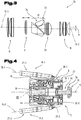
- the inner focusing lens 6 is shifted in the axial direction of the optical axis 17-1, 17-2, with the rotary movement of the focusing knob 10 via a focusing gear 11 ( Fig. 4 ) is converted into a longitudinal movement and corresponding displacement of the focusing lens 6.
- the Fig. 4 shows a longitudinal section of the focusing device 7 of the telescope 1 in detail with parts of the two focusing lenses 6 ( Fig. 3 ) leading focusing gear 11-1, 11-2.
- the focussing device 7 has the housing 8 and the focussing button 10 rotatably mounted about the axis of rotation 9 as central elements.
- the housing 8 of the focusing device 7 is fastened in a rotationally fixed manner to one of the two tubes 2-1, 2-2 in the area of the articulated bridge 5-1. This fastening of the housing 8 of the focusing device 7 takes place jointly on a joint axis 29 of the joint bridge 5 of the two tubes 2.
- the axis nut 30 and lock nut 31 used for this purpose are also in the Fig. 4 shown.
- a threaded spindle 12 is arranged displaceably in the axial direction (axis of rotation 9).
- the focusing device 7 has a push rod 27 in each case.
- a driver 28 fastened to an end region of the push rod 27 on the eyepiece side is in engagement with the threaded spindle 12.
- One end of the push rod 27 can be arranged in one of the tubes 2-1, 2-2 and another end of the push rod 27 in the articulated bridge 5.
- the Fig. 5 shows the cross section of the focusing device 7 according to FIG Fig. 4 , the housing 8, the threaded spindle 12 and the focusing knob 10 being shown in a separated state or in a dismantled state.
- the threaded spindle 12 comprises an inner sleeve 32 with a front adjusting disk 33 and a rear adjusting disk 34.
- a driver head 35 of the driver 28 extends between facing end faces of the front adjusting disk 33 and the rear adjusting disk 34, wherein the front adjusting disk 33 on the one hand and the rear adjusting disk 34 come to rest on the driver head 35 and an axial displacement of the threaded spindle 12 is converted into a corresponding movement of the push rods 27-1, 27-2.
- the two adjusting disks 33, 34 are arranged on a cylinder jacket section of the inner sleeve 32, the rear adjusting disk 34 on a radially protruding shoulder of the inner sleeve 32 comes to the plant.
- a compression spring 36 formed by a spiral spring is fastened to the inner sleeve 32 and, in the pretensioned state, holds the front adjusting disk 33, the driver head 35 and the rear adjusting disk 34 pressed against one another.
- An axle sleeve 37 is arranged in the interior of the housing 8 of the focusing device 7 and is connected to the housing 8.
- This axle sleeve 37 of the focusing device 7 serves as a straight guide for the threaded spindle 12.
- the inner sleeve 32 of the threaded spindle 12 is displaceable on the axle sleeve 37 of the housing 8 in the axial direction.
- a slot 38 extending in the longitudinal direction of the axle sleeve 37 is provided according to this embodiment ( Fig. 6 ).
- a guide pin 39 protruding inwardly on an inner circumference of the inner sleeve 32 of the threaded spindle 12, which engages in the slot 38 of the axle sleeve 37. That is to say, in the assembled state of the focusing device 7, the guide pin 39 extends through the slot 38 of the axle sleeve 37. This restricts the movement of the threaded spindle 12 to a translation 45 in the direction of the axis of rotation 9 ( Fig.
- a thread 40 is formed on an outer circumference of the threaded spindle 12, on which a corresponding internal thread 41 of a drive bushing 42 of the focusing knob 10 engages.
- the drive bushing 42 of the focusing knob 10 is rotatably mounted in the housing 8 of the focusing device 7.
- the focusing knob 10 is thus arranged to be stationary in the axial direction (axis of rotation 9).
- a rotation of the focusing knob 10 thus causes an axial displacement of the threaded spindle 12 with the two adjusting disks 33, 34, as a result of which - via the drivers 28-1, 28-2 and the push rods 27-1, 27-2 - the focusing lenses 6 are moved in the axial direction ( Fig. 3 ).
- the Fig. 6 shows the focusing knob 10, the threaded spindle 12 and the housing 8 of the focusing device 7 shown in section according to FIG Fig. 5 .
- the representation corresponds to a viewing direction pivoted by 90 °.
- the slot 38 which extends in the longitudinal extension of the axle sleeve 37 and in which the guide pin 39 slides along, can be seen more clearly.
- the slot 38 can also be designed as an elongated hole.
- the range of rotation or the angle of rotation of the focusing knob 10 relative to the housing 8 of the focusing device 7 is limited by a stop at both ends of the range of rotation, the range of rotation being more than 360 ° amounts to.
- the stops 13-1, 13-2 are arranged offset from one another.
- the stops 13-1, 13-2 can be offset from one another with respect to a longitudinal direction of the axis of rotation 9 or about the axis of rotation 9.
- the focusing knob 10 comprises a stop bolt or a stop element 43, which is connected to the focusing knob 10 in a rotationally fixed manner.
- this stop element 43 extends inside the axle sleeve 37 of the housing 8.
- the stop element 43 like the axle sleeve 37, is arranged coaxially to the common axis of rotation 9 of the focusing button 10.
- a thread-like groove 44 is formed or molded into it.
- the guide pin 39 of the inner sleeve 32 of the threaded spindle 12 also extends into the groove 44 ( Fig. 4 ).
- the Fig. 7 shows a detail of the device for limiting the rotary movement of the focusing knob 10 in an end position, according to FIG Fig. 4 , shown in perspective. For the sake of clarity, only the stop element 43 of the focusing knob 10 and the guide pin 39 of the threaded spindle 12 are shown.
- the guide pin 39 is moved when turning the focusing knob 10 in the direction of the longitudinal extension of the slot 38 of the axle sleeve 37 (in the direction of the axis of rotation 9). So it only carries out a translation 45.
- the stop element 43 executes a pure rotational movement 46 when the focusing knob 10 is turned.
- the movement of the guide pin 39 relative to the stop element 43 is that of a screw movement, the guide pin 39 moving along the helically formed groove 44.
- the height of one turn of the groove 44 is equal to the pitch of the mutually engaging threads of the threaded spindle 12 and of the focusing knob 10 (thread 40, internal thread 41).
- the arc length of the groove 44 (the length corresponding to a helical line) is limited by a first stop 13-1 and a second stop 13-2.
- These stops 13-1, 13-2 are formed by a front and a rear inner wall of the groove 44, these inner walls preferably being aligned approximately perpendicularly with respect to a direction of the relative movement between the guide pin 39 and the groove 44.
- the rotary movement of the focusing knob 10 therefore comes to an end at a precisely defined angle of rotation, namely when the front stop 13-1 or the rear stop 13-2 comes to rest on the guide pin 39.
- the second situation is precisely that which occurs in the Fig. 7 is shown, the rear stop 13-2 resting on the guide pin 39.
- the two stops 13-1, 13-2 on the stop element 43 are formed by independent stop bodies that protrude radially from an outer cylinder jacket side of the stop element 43.
- Such an alternative design of the stop element 43 accordingly also requires less material for its manufacture.
- the Fig. 8 shows a detail of the focusing device 7 ( Fig. 4 ) in perspective Representation and partly shown as an exploded view.
- the diopter ring 23 is mounted pivotably with respect to the axis of rotation 9 ( Fig. 5, 6 ).
- the two adjusting disks 33, 34 are arranged on a cylinder jacket section of the inner sleeve 32 of the threaded spindle 12. Depending on how they are fastened, the two adjusting disks 33, 34 can also be pivoted on the inner sleeve 32 with respect to the axis of rotation 9, this pivoting being effected by actuating the diopter ring 23.
- the diopter ring 23 has a driver arm 47.
- the driver arm 47 extends, projecting from the annular section of the diopter ring 23, parallel to the axis of rotation 9 in the direction of the lens side.
- the adjusting disks 33, 34 have recesses 48-1, 48-2 on their circumference. Since the driver arm 47 of the diopter ring 23 engages in the recesses 48-1, 48-2 of the adjusting disks 33, 34, these can be pivoted with respect to the axis of rotation 9 by actuating the diopter ring 23.
- one driver head 35 of the driver 28 of the two push rods 27-1, 27-2 is carried along between the facing end faces of the front adjusting disk 33 and the rear adjusting disk 34 and takes place in this way when the threaded spindle 12 is axially displaced a corresponding displacement of the focusing lenses 6.
- an additional displacement of one of the two focusing lenses 6 can now also be achieved by pivoting the diopter ring 23.
- sections or partial areas of the end faces of the two adjusting disks 33, 34 coming into contact with the driver heads 35 are designed to run differently.
- annular sides are provided in one of the two sub-areas, while in the other sub-area there are thread-like or helical sides. Accordingly, a helically extending first guide track 49-1 is formed in a first sub-area and a circular second guide track 49-2 is formed in a second sub-area through the two adjusting disks 33, 34.
- FIG. 8 the arrangement of the two adjusting disks 33, 34 also shown from the rear, that is, in a side view marked with "R".
- this design of the two adjusting disks 33, 34 when the diopter ring 23 is actuated, there is an additional displacement of the focusing lens 6 of the first tube 2-1 (thread-like guideway 49-1).
- the pivoting of the arrangement of the two adjusting disks 33, 34 when the diopter ring 23 is actuated does not cause any displacement of the focusing lens 6 of the second tube 2-2 (second guide track 49-2 running in the shape of an arc of a circle).
- the driver arm 47 of the diopter ring 23 is sufficient to be able to interact with the recesses 48-1, 48-2 on the adjusting disks 33, 34 into the interior of the cylinder jacket-shaped housing 8 Fig. 6
- the driver arm 47 has a radially extending section with which it is connected to the annular section of the diopter ring 23.
- the housing 8 of the focusing device 7 has, in the eyepiece-side end area of its cylinder jacket-shaped section, a slot 50 running over a partial area of the circumference through which the driver arm 47 extends ( Fig. 8 ).
- a first window 51-1 and a second window 51-2 are also formed ( Fig. 5 , 8th ), through which one of the two drivers 28-1, 28-2 of the focusing gear 11 extends.
- the driver heads 35-1, 35-2 of the drivers 28-1, 28-2 can engage in the adjusting disks 33, 34 and transmit an axial displacement to the push rods 27-1, 27-2 ( Fig. 4 ).
- the Fig. 9 shows a representation of parts of the binocular telescope 1 in a frontal view viewed from the object side in a viewing direction directed parallel to the joint axis 4.
- the binocular telescope 1 Of the binocular telescope 1, only the focusing device 7 (recognizable by the focusing button 10 and the focusing gear 11-1) with the driver 28-1, the push rod 27-1 and the lens mount 26-1 of the focusing lens 6 of the first tube 2-1 shown.
- one of the lenses of the eyepiece 19 is also shown.
- the first optical axis 17-1 of the objective 18 and the second optical axis 17-2 of the eyepiece 19 are offset parallel to one another by the distance 21.
- first optical axis 17-1 of the objective 18, the second optical axis 17-2 of the eyepiece 19 and the joint axis 4 of the joint bridge 5 lie in a common plane 22. This is also the case in an analogous manner when the optical system 24 is arranged in the second tube 2-2, which is arranged symmetrically to the first tube 2-1.
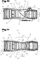
- Fig. 10 is a cross section through the first tube 2-1 with respect to a through the plane 22 ( Fig. 9 ) formed section plane shown. That is, the representation corresponds to a viewing direction perpendicular to the plane 22 containing the first optical axis 17-1 of the objective 18, the second optical axis 17-2 of the eyepiece 19 and the hinge axis 4.
- the alignment of the prism erecting system 20 in FIG Fig. 10 corresponds to that as in Fig. 3 shown.
- the distance 21 between the first optical axis 17-1 of the objective 18 and the second optical axis 17-2 of the eyepiece 19 also appears undistorted in the figure.
- the Fig. 11 shows a cross section of the first tube 2-1 with respect to a section plane "BB" containing the second optical axis 17-2 of the eyepiece 19 and perpendicular to the plane 22 ( Fig. 9 ).
- BB section plane
- an outer side 52-1 of a tube housing 57 has a waist 53 in the region of the prism erecting system 20.
- the waist 53 is formed with a circumferential shape deviating from a circular shape.
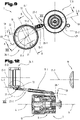
- a section running on an upper side of the tube 2-1 is designed as a holding trough 14-1 following the waist 53 for a section of a finger, as shown in FIG Figures 15 and 16 is shown.
- a section running on an underside of the tube 2-1 is designed as a holding trough 14-2 following the waist 53 for a section of a user's thumb.
- a plane 66 running through the holding trough 14-1 on the upper side of the tube 2-1 and a plane 66 running through the holding trough 14-2 on the underside of the tube 2-1 runs through the prism erecting system 20 or intersects it.
- each holding trough 14-1, 14-2 can have a concave cross-section transversely to the longitudinal direction of the waist 53.
- a longitudinal direction 67 of each holding trough 14-1, 14-2 can run obliquely to a longitudinal extension of the tube 2-1 (optical axes 17-1, 17-2). Furthermore, a longitudinal direction 67-1 of the holding trough 14-1 running on the top and / or a longitudinal direction 67-2 of the holding trough 14-2 running on the underside can enclose at least an angle 68 between 35 ° and 90 ° with a direction of the hinge axis 4 .
- the longitudinal direction 67 of a holding trough 14 should be understood to mean the direction of a course of the valley floor of the holding trough 14, as shown in FIG Figures 15 and 16 is indicated by dashed lines. That is to say, the sequence of points of the local minima of the radial distances from the intersection curves containing the optical axis 17-1 or 17-2 through the outside 52 of the tube housing 57 characterizes the longitudinal direction 67.
- each holding trough 14-1, 14-2 of each tube 2-1 can have a first end region on the eyepiece side, which is closer to the eyepiece 19, and a second end region on the objective side, which is closer to the objective 18.
- the distance between the respective eyepiece-side end regions of the holding troughs 14-1, 14-2 of the two tubes 2-1, 2-2 is smaller than the distance between the respective lens-side end regions of the holding troughs 14-1, 14-2 of the two tubes 2- 1, 2-2.
- Each tube 2-1, 2-2 has, in the region of its waist 53, two holding depressions 14-1, 14-2 which lie opposite one another, in particular two holding troughs 14-1, 14-2 which are arranged on sections of the tube 2-1, 2-2 rotated by 180 ° relative to one another. That is to say, holding troughs 14-1, 14-2 of the binocular telescope 1 are offset from one another with respect to a rotation by 180 ° relative to the optical axes 17-1, 17-2.
- the holding troughs 14-1, 14-2 of the two tubes 2-1, 2-2 can run towards one another in a V-shape, with a holding trough 14-1, 14-2 of a first of the two tubes 2-1, 2-2 being a first Leg of the V and a recess 14-1, 14-2 of a second of the two tubes 2-1, 2-2 forms a second leg of the V ( Fig. 1 ).
- a tip of the V can lie in the area of the focusing knob 10.
- imaginary extensions of the longitudinal extensions 67-1, 67-2 of the retaining troughs 14-1, 14-2, maintaining an orientation of the holding troughs 14-1, 14-2 can also run through the focusing button 10, or the focusing button 10 can run between an imaginary, the orientation of the holding depressions 14-1, 14-2 can be arranged extension of the longitudinal extensions 67-1, 67-2.
- a value of a diameter 54 of the waist 53 measured perpendicularly with respect to the plane 22 is in a ratio of less than 80%, preferably approx. 67% ( Fig. 11 ).
- the outer sides 52 of the two of the tubes 2-1, 2-2 are preferably shaped in a waisted manner such that a ratio of the diameter 54 of the waist 53 to the corresponding diameter 55 of the cylinder jacket 56 enveloping the outer side 52 is in a range between 0.60 and 0 .80 (or between 60% and 80%).
- a cross section through each of the tubes 2-1, 2-2 in the region of the waist 53 which is oriented normal to the first plane 22 and to the direction of the optical axis 17-1, 17-2 (corresponds to plane 66) its narrowest point with respect to a direction perpendicular to the first plane 22 on ( Fig. 9 , 11 ).
- a ratio of a clear height 69 of the narrowest point of the tube 2-1, 2-2 normal to the first plane 22 has a value of less than 80%, in particular between 60% and 80%, to a maximum free diameter 70 of the objective 18.
- the waist 53 has a circumferential shape deviating from a circular shape.
- the diameters of the tubes 2-1, 2-2 in the region of the waist 53, measured perpendicularly with respect to the optical axis 17-1, 17-2, have different values depending on the direction - unlike a circular cross section. That is, the diameter 54 of the waist 53 measured perpendicularly with respect to the plane 22 corresponds to the narrowest point and diameters measured in other directions have larger values.
- the waist of the outer sides 52 of the tubes 2-1, 2-2 is advantageous insofar as it enables a user to grasp and hold the binocular telescope 1 particularly comfortably and at the same time safely.
- the diameter 55 has a value of 51.5 mm and the diameter 54 of the waist 53 has a value of 35 mm.
- the value of the maximum free diameter 70 of the objective 18 in these tubes 2-1, 2-2 is 42 mm and the value of the clear height 69 of the narrowest point is 29 mm.
- a second exemplary embodiment of the tubes 2-1, 2-2 provides the corresponding values: the value of the diameter 55 of the cylinder jacket 56, which is intended to circumscribe the outer sides 52 of the tube 2, is 44.5 mm; The value of the diameter 54 of the waist 53 is 33.5 mm; value the maximum free diameter 70 of the objective 18 is equal to 32 mm and the value of the clear height 69 of the narrowest point of the tube is 25.5 mm.
- the outer shape of the tubes 2-1, 2-2 of the binocular telescope 1 is particularly well characterized by the ratio of the difference between the two diameters 55, 54 to the maximum free diameter 70 of the objective 18 (table, column 9).
- the value of this ratio in the binocular telescope 1 according to the invention is in a range greater than 0.20, preferably in a range between 0.30 and 0.60.
- values of the distance 21 by which the first optical axis 17-1 of the objective 18 and the second optical axis 17-2 of the eyepiece 19 are offset in parallel relative to one another should also be mentioned at this point.
- the distance 21 has a value of 3.2 mm and in example 2 a value of 2.9 mm. Values of the distance 21 from a range from 2 mm to 10 mm have proven to be advantageous.
- This configuration of the outer shape of the binocular telescope 1 or the outer shape of the tube housing 57 is also favored by the fact that, according to this exemplary embodiment, a special design of the prisms of the prism erecting system 20 is also implemented.
- a special design of the prisms of the prism erecting system 20 is also implemented.
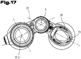
- in comparison to the theoretical basic shape of the two prisms of a Schmidt-Pechan prism in the embodiment in question in the radial direction - with respect to the optical axis 17-1, 17-2 - protruding corners are replaced by bevels, as best in FIG Fig. 3 , but also in Fig. 17 can be seen.
- the Fig. 12 shows a cross section of the binocular telescope 1 in a reduced representation according to FIG Fig. 9 .
- the illustrated parts of the binocular telescope 1 are the same as in FIG Fig. 9 onto a lens representing the eyepiece 19 and the focusing device 7 with the focusing gear 11 and the lens mount 26 of the focusing lens 6 ( Fig. 3 ) limited.
- the in Fig. 12 The cross section shown corresponds to a sectional plane which is determined by a plane 59 containing the joint axis 4 (or the axis of rotation 9) and the longitudinal axis 15 of the push rod 27.
- the push rod 27 is aligned obliquely with respect to the hinge axis 4, wherein - according to this exemplary embodiment - its longitudinal axis 15 encloses an acute angle 58 with a value of 7 ° with the hinge axis 4.
- the value of the angle 58 is preferably selected from a range between 0 ° and 30 °.
- the longitudinal axis 15 is, however, arranged in a so-called crooked position.
- the arrangement of the various axes relative to one another is better shown in the illustration Fig. 9 to recognize.
- the joint axis 4 spans the common plane 22 on the one hand with the optical axes 17-1, 17-2 and on the other hand, together with the longitudinal axis 15 of the push rod 27, the common plane 59.
- These two planes that is, the plane 22 and the plane 59, enclose an angle 60 with a value from a range between 0 ° and 30 °, in particular between 10 ° and 30 °. In the example shown, the angle 60 has a value of 12 °.
- This arrangement or alignment of the push rod 27 is implemented by a corresponding hole in the tube housing 57, which extends from the area of the articulated bridge 5-1, 5-2 or the area of the focusing device 7 extends to the lens mount 26 of the focusing lens 6 ( Fig. 13 ).
- the push rod 27 can thus be displaced back and forth in the tube housing 57 in the direction of its longitudinal axis 15.
- the Fig. 13 shows a cross section of the first tube 2-1 of the binocular telescope 1 according to a sectional plane formed by the plane 59. Ie the cutting plane contains the joint axis 4 and the longitudinal axis 15 of the push rod 27-1 ( Fig. 9 ).
- the tube housing 57 has a bore or a guide tunnel 61 in which the push rod 27-1 is mounted.
- the guide tunnel 61 accordingly extends from the inside of the tube housing 57, in the area of the lens mount 26 of the focusing lens 6, to the area of the first articulated bridge 5-1, where it opens outward on an eyepiece-side end of the first articulated bridge 5-1.
- a window 62 is also formed between the guide tunnel 61 and the focusing device 7, directed in the radial direction towards the joint axis.
- the driver 28-1 extends through this window 62 from the push rod 27-1 into the housing 8 of the focusing device 7 ( Fig. 12 ).
- the arrangement of the push rods 27-1, 27-2 in the binocular telescope 1 is thus provided such that they extend from the interior of the tube housing 57 into the first articulated bridge 5-1.
- the design of the binocular telescope 1 with the described, obliquely arranged push rods 27 and the corresponding guide tunnels 61 in the tube housings 57 of the tubes 2-1, 2-2 offers the possibility, particularly when assembling the binocular telescope 1, that a Adjustment of the focusing device can be made. Such an adjustment is possible by acting with a suitable tool through the eyepiece-side end of the guide tunnel 61 on the eyepiece-side end region of the push rod 27.
- the push rods 27 are namely, as below with reference to FIG Fig. 14 will be described, telescopically adjustable in length.
- a central basic position for the required adjustment ranges can thus be made both for focusing and for dioptric compensation.
- the Fig. 14 shows the push rod 27-1 shown as a longitudinal section with respect to its longitudinal axis 15-1.
- the push rods 27-1, 27-1 are preferably straight.
- the main components of the push rod 27-1 are an inner rod 63 and a push sleeve 64.
- a slide bushing 65 is also shown, through which the push rod 27-1 in the guide tunnel 61 is stored.
- the inner rod 63 and the push sleeve 64 are preferably designed with interlocking threads and can thus be adjusted in their relative length to one another in the direction of the longitudinal axis 15-1.
- the driver 28-1 is fastened to an end of the push sleeve 64 on the eyepiece side.
- an end of the inner rod 63 on the lens side is formed with a joint head arrangement 71.
- This joint head arrangement 71 in turn engages with a joint socket 72 of the lens mount 26 of the focusing lens 6.
- the joint socket 72 is formed by a fork protruding laterally from the lens mount 26 of the focusing lens 6 (see also FIG Figures 9, 12 ).
- the joint head arrangement 71 is preferably also designed with a pretensioned spring element and a washer, by means of which a play-free contact between corresponding contact sides of the joint socket 72 and the joint head arrangement 71 is achieved on the other hand in both adjustment directions.
- a play-free contact between corresponding contact sides of the joint socket 72 and the joint head arrangement 71 is achieved on the other hand in both adjustment directions.
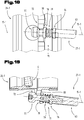
- the coupling or the mutual engagement of the push rod 27 and the lens mount 26 of the focusing lens 6 is based on the Figures 18 and 19 detailed.
- the Fig. 18 shows a detail of the lens mount 26 with the joint head arrangement 71 of the push rod 27 according to FIG Fig. 12 .
- the illustration corresponds to a lateral plan view of the lens mount 26 corresponding to a viewing direction parallel to the section plane “XIX-XIX” as in FIG Fig. 9 displayed.
- the Fig. 19 shows a cross section corresponding to a sectional plane containing the optical axis 17-1 with the focusing lens 6, the joint socket 72 of the lens mount 26 and the joint head arrangement 71 of the push rod 27.
- the joint head arrangement 71 is attached to the inner rod 63 of the push rod 27 by means of a joint head base 76.
- the joint head base 76 is screwed into the end of the inner rod 63 on the objective side.
- a cylindrical portion of a joint head 77 is attached to the joint head base 76.
- a sliding disk 78 and a compression spring 79 are mounted on the cylindrical section of the joint head 77.
- the compression spring 79 is arranged in such a way that it is supported on the one hand on the sliding disk 78 and on the other hand on a disk-shaped projection of the joint head base 76.
- the compression spring 79 is installed and in a pretensioned state In this way, the fork-shaped joint socket 72 of the lens mount 26 of the focusing lens 6 is clamped or clamped between the sliding disk 78 and the joint head 77.
- the transmission of a movement from the push rod 27 to the lens mount 26 of the focusing lens 6 can thus take place free of mechanical play.
- a radial compensation movement of the joint head 77 in the joint socket 72 - with respect to the optical axis 17-1 - is possible.
- a flank 80 on the eyepiece side or a flank 80 facing the sliding disk 78 has an inclination or inclination corresponding to the longitudinal axis 15 of the push rod 27.
- the sliding disk 78 rests almost over the entire surface on the flank 80 of the joint socket 72. In particular, this prevents the sliding disk 78 from jamming on the cylindrical section of the joint head 77.
- the inner rod 63 and the push sleeve 64 of the push rod 27-1 it is also provided that the inner rod 63 extends through the push sleeve 64 in the direction of the longitudinal axis 15-1 and protrudes therefrom - beyond the end region on the eyepiece side.
- a slot in the end region of the inner rod 63 on the eyepiece side enables a screwdriver, for example, to act, with which a length change or an adjustment setting can be made on the push rod 27-1.
- the tube 2-1 in a cross section of the tube 2-1 corresponding to the first plane 22 in a section covering the prism reversing system 20 has the greatest distance between each other Insides and thus its widest point.
- a cross section normal to the first plane 22 and to the direction of the optical axis through the tube 2-1 in the region of the waist 53 thus has its widest point in a region of intersection of the tube 2-1 with the first plane 22.
- a tip 73 of a roof edge 74 of the prism erecting system 20 is arranged in a region of the widest point and pointing outwards ( Fig. 10 ).
- the shortest distance between this tip 73 of the roof edge 74 and the inner wall of the tube 2-1 is smaller as the shortest distance between the tip 73 of the roof edge 74 and the optical axis 17-1 of the objective 18 and / or to the optical axis 17-2 of the eyepiece 19.
- the tip 73 of the roof edge 74 of the prism reversing system 20 is thus arranged in the area of the widest point and pointing outwards, so that the shortest distance between the tip 73 of the roof edge 74 and the inner wall of the tube 2-1 is smaller than the shortest distance between the tip 73 the roof edge 74 and a surface 75 of the prism erecting system 20 opposite the tip 73 of the roof edge 74.
- FIG. 20 shows a detail according to a plan view of the end area of the binocular telescope 1 on the eyepiece side.
- the illustration corresponds to a direction of view of the binocular telescope 1 parallel to the longitudinal axis 15 of the push rod 27 ( Fig. 12 ).
- a diopter ring 81 is provided, which is arranged asymmetrically to the joint axis 4 of the tubes 2-1, 2-2 of the telescope 1.
- This diopter ring 81 is arranged in an area between the joint axis 4 and the first tube 2-1. In particular, it is positioned in the area of the first articulated bridge 5-1 and particularly close to the end area of the push rod 27-1 on the eyepiece side ( Fig. 1 , 12th ).
- the Fig. 21 shows a detail of the articulated bridge 5-1 of the telescope 1 with the diopter ring 81 shown partially in section.
- the representation again corresponds to a viewing direction parallel to the longitudinal axis 15 of the first push rod 27-1.
- a diopter gear 82 is provided between the diopter ring 81 and the inner rod 63 of the push rod 27-1.
- This is formed in this embodiment by a gear transmission.
- a first gear 83 is connected to the diopter ring 81 and an actuation of the diopter ring 81 is thus transmitted to a second gear 84.
- a so-called sleeve coupling is formed between the second gear 84 and the eyepiece-side end region of the inner rod 63.
- the second gear 84 engages the end of the inner rod 63 in a form-fitting manner, so that a rotational movement is transmitted to the inner rod 63.
- the end of the inner rod 63 is designed with a triangular profile.
- the second gear 84 is not firmly connected to the inner rod 63, but can move the inner rod 63 relative to the gear 84 in the direction of the longitudinal axis 15-1. Because of the other hand between the Thrust sleeve 64 and the thread formed on the inner rod 63, when the gear 84 is rotated, there is an additional axial displacement of the inner rod 63 with the joint head arrangement 71 in the direction of the longitudinal axis 15-1.
- the diopter ring 81 and the gears 83, 84 of the diopter gear 82 are not shifted in the direction of the longitudinal axis 15-1.
- an actuation of the focusing button 10 and thus an axial displacement of the entire push rod 27-1 also remains without any interaction on the setting of the diopter ring 81 or the diopter gear 82.
- All information on value ranges in the present description should be understood to include any and all sub-areas, e.g. the information 1 to 10 should be understood to include all sub-areas, starting from the lower limit 1 and the upper limit 10 , ie all sub-ranges begin with a lower limit of 1 or greater and end at an upper limit of 10 or less, for example 1 to 1.7, or 3.2 to 8.1, or 5.5 to 10.
Landscapes
- Physics & Mathematics (AREA)
- General Physics & Mathematics (AREA)
- Optics & Photonics (AREA)
- Astronomy & Astrophysics (AREA)
- Telescopes (AREA)
Applications Claiming Priority (1)
| Application Number | Priority Date | Filing Date | Title |
|---|---|---|---|
| ATA50994/2019A AT522808B1 (de) | 2019-11-15 | 2019-11-15 | Fernrohr mit schwenkbarer Gelenkbrücke |
Publications (3)
| Publication Number | Publication Date |
|---|---|
| EP3832372A2 true EP3832372A2 (fr) | 2021-06-09 |
| EP3832372A3 EP3832372A3 (fr) | 2021-08-11 |
| EP3832372B1 EP3832372B1 (fr) | 2025-06-25 |
Family
ID=73597757
Family Applications (1)
| Application Number | Title | Priority Date | Filing Date |
|---|---|---|---|
| EP20207274.0A Active EP3832372B1 (fr) | 2019-11-15 | 2020-11-12 | Lunette pourvue de pont articulé pivotant |
Country Status (3)
| Country | Link |
|---|---|
| US (1) | US11914136B2 (fr) |
| EP (1) | EP3832372B1 (fr) |
| AT (1) | AT522808B1 (fr) |
Families Citing this family (1)
| Publication number | Priority date | Publication date | Assignee | Title |
|---|---|---|---|---|
| AT522799B1 (de) * | 2019-11-15 | 2021-02-15 | Swarovski Optik Kg | Fernrohr mit zwei Tuben mit Taille |
Family Cites Families (20)
| Publication number | Priority date | Publication date | Assignee | Title |
|---|---|---|---|---|
| US1364381A (en) * | 1919-02-01 | 1921-01-04 | Kent Arthur Atwater | Prismatic telescope |
| US3528724A (en) | 1964-06-25 | 1970-09-15 | Etat Francais French State | Binocular observation and sighting instruments |
| DE1241144B (de) * | 1964-09-02 | 1967-05-24 | D & D Company Inc | Schwimmfaehiges Fernglas |
| DE1547239A1 (de) | 1964-09-02 | 1969-11-06 | D & D Company Inc | Justiereinrichtung fuer binokulare Fernglaeser |
| GB1427004A (en) * | 1972-02-15 | 1976-03-03 | Secr Defence | Optical instruments |
| DE2365071A1 (de) | 1973-12-28 | 1975-07-03 | Christian R Schlotz | Binokulares fernglas |
| US4601552A (en) * | 1984-10-22 | 1986-07-22 | Jessmore Floyd E | Binocular construction having adjustable filters |
| DE9201269U1 (de) * | 1992-02-03 | 1992-04-09 | Hohen-Hinnebusch, Hans-Ingo, 4358 Haltern | Binokulares Fernglas |
| JP2005309094A (ja) * | 2004-04-21 | 2005-11-04 | Pentax Corp | 双眼鏡 |
| JP4974537B2 (ja) | 2006-02-08 | 2012-07-11 | 鎌倉光機株式会社 | 焦点調節装置及び光学機器 |
| DE102007020529B4 (de) * | 2007-05-02 | 2010-11-04 | Minox Gmbh Optische Und Feinmechanische Werke | Binokulares Fernglas |
| DE102008003414A1 (de) * | 2008-01-08 | 2009-07-09 | Carl Zeiss Sports Optics Gmbh | Binokulares Fernglas |
| AT506437B1 (de) * | 2008-01-31 | 2011-08-15 | Swarovski Optik Kg | Beobachtungsgerät mit entfernungsmesser |
| DE102010025136A1 (de) | 2010-06-25 | 2011-12-29 | Steiner-Optik Gmbh | Binokulares Fernrohr |
| DE102011110991A1 (de) | 2011-08-18 | 2013-02-21 | Carl Zeiss Sports Optics Gmbh | Verstelleinrichtung an einem optischen Gerät |
| EP2605055A1 (fr) | 2011-12-15 | 2013-06-19 | Carl Zeiss Sports Optics GmbH | Jumelles destinées à la représentation d'un objet |
| DE102012200514A1 (de) * | 2012-01-13 | 2013-07-18 | Carl Zeiss Sports Optics Gmbh | Optisches System zur Abbildung eines Objekts sowie Verfahren für das optische System |
| DE102012200521A1 (de) * | 2012-01-13 | 2013-07-18 | Carl Zeiss Meditec Ag | Optisches System zur Abbildung eines Objekts |
| DE102013013480A1 (de) * | 2013-08-15 | 2015-02-19 | Carl Zeiss Sports Optics Gmbh | Fernoptisches Gerät, insbesondere Binokuiar |
| JP6606617B2 (ja) * | 2016-08-04 | 2019-11-13 | 株式会社ニコンビジョン | 双眼鏡及び接眼レンズ |
-
2019
- 2019-11-15 AT ATA50994/2019A patent/AT522808B1/de active
-
2020
- 2020-11-10 US US17/093,881 patent/US11914136B2/en active Active
- 2020-11-12 EP EP20207274.0A patent/EP3832372B1/fr active Active
Also Published As
| Publication number | Publication date |
|---|---|
| EP3832372A3 (fr) | 2021-08-11 |
| EP3832372B1 (fr) | 2025-06-25 |
| US20210149181A1 (en) | 2021-05-20 |
| AT522808B1 (de) | 2021-02-15 |
| AT522808A4 (de) | 2021-02-15 |
| US11914136B2 (en) | 2024-02-27 |
Similar Documents
| Publication | Publication Date | Title |
|---|---|---|
| EP3822688B1 (fr) | Lunette pourvue de deux tubes à col | |
| EP0961147B1 (fr) | Télescope binoculaire | |
| DE19521710B4 (de) | Panoramakopf für optische Geräte, insbesondere für Fotoapparate | |
| DE69216763T2 (de) | Feldstecher mit Einzelfokussierung | |
| DE4013512A1 (de) | Schalteinrichtung zum umschalten eines kraftgetriebenen werkzeugs | |
| DE102004005538B4 (de) | Nockenmechanismus für einen Objektivtubus | |
| DE29720737U1 (de) | Zielfernrohr | |
| DE102012220578A1 (de) | Endoskop mit schwenkbarer Optik | |
| DE3028783C2 (fr) | ||
| EP4357834B1 (fr) | Lunette et dispositif de mise au point | |
| EP3822683B1 (fr) | Dispositif de mise au point de lunette et limitation de rotation | |
| DE60115185T2 (de) | Linearer Antrieb für Endoskop mit Drehanschlag | |
| EP3832372B1 (fr) | Lunette pourvue de pont articulé pivotant | |
| DE3128642A1 (de) | Zoomobjektivaufbau | |
| WO2009137860A1 (fr) | Appareil d'observation téléoptique | |
| DE102012009990B4 (de) | Binokulare fernoptische Einrichtung | |
| DE2841611B2 (de) | Feldstecher | |
| DE102012025700B3 (de) | Binokulare fernoptische Einrichtung | |
| DE2717575C3 (de) | Doppelfernrohr | |
| DE2717574B2 (de) | Doppelfernrohr mit zwei Drehachsen | |
| DE2346758A1 (de) | Aufnahmeobjektiv fuer kameras | |
| DE102018108088B4 (de) | Stabeinsetzinstrument | |
| WO1997038641A1 (fr) | Clou intramedullaire pour osteosynthese | |
| DE1926430C (de) | Feldstecher | |
| DE102008001775A1 (de) | Werkzeugmaschine, insbesondere handgehaltene Werkzeugmaschine |
Legal Events
| Date | Code | Title | Description |
|---|---|---|---|
| PUAI | Public reference made under article 153(3) epc to a published international application that has entered the european phase |
Free format text: ORIGINAL CODE: 0009012 |
|
| STAA | Information on the status of an ep patent application or granted ep patent |
Free format text: STATUS: THE APPLICATION HAS BEEN PUBLISHED |
|
| AK | Designated contracting states |
Kind code of ref document: A2 Designated state(s): AL AT BE BG CH CY CZ DE DK EE ES FI FR GB GR HR HU IE IS IT LI LT LU LV MC MK MT NL NO PL PT RO RS SE SI SK SM TR |
|
| PUAL | Search report despatched |
Free format text: ORIGINAL CODE: 0009013 |
|
| AK | Designated contracting states |
Kind code of ref document: A3 Designated state(s): AL AT BE BG CH CY CZ DE DK EE ES FI FR GB GR HR HU IE IS IT LI LT LU LV MC MK MT NL NO PL PT RO RS SE SI SK SM TR |
|
| RIC1 | Information provided on ipc code assigned before grant |
Ipc: G02B 23/18 20060101AFI20210705BHEP |
|
| STAA | Information on the status of an ep patent application or granted ep patent |
Free format text: STATUS: REQUEST FOR EXAMINATION WAS MADE |
|
| 17P | Request for examination filed |
Effective date: 20220209 |
|
| RBV | Designated contracting states (corrected) |
Designated state(s): AL AT BE BG CH CY CZ DE DK EE ES FI FR GB GR HR HU IE IS IT LI LT LU LV MC MK MT NL NO PL PT RO RS SE SI SK SM TR |
|
| RAP1 | Party data changed (applicant data changed or rights of an application transferred) |
Owner name: SWAROVSKI-OPTIK AG & CO KG. |
|
| STAA | Information on the status of an ep patent application or granted ep patent |
Free format text: STATUS: EXAMINATION IS IN PROGRESS |
|
| P01 | Opt-out of the competence of the unified patent court (upc) registered |
Effective date: 20230525 |
|
| 17Q | First examination report despatched |
Effective date: 20230616 |
|
| GRAP | Despatch of communication of intention to grant a patent |
Free format text: ORIGINAL CODE: EPIDOSNIGR1 |
|
| STAA | Information on the status of an ep patent application or granted ep patent |
Free format text: STATUS: GRANT OF PATENT IS INTENDED |
|
| RIC1 | Information provided on ipc code assigned before grant |
Ipc: G02B 23/02 20060101ALN20250113BHEP Ipc: G02B 7/12 20210101ALI20250113BHEP Ipc: G02B 7/06 20210101ALI20250113BHEP Ipc: G02B 23/18 20060101AFI20250113BHEP |
|
| INTG | Intention to grant announced |
Effective date: 20250203 |
|
| GRAS | Grant fee paid |
Free format text: ORIGINAL CODE: EPIDOSNIGR3 |
|
| GRAA | (expected) grant |
Free format text: ORIGINAL CODE: 0009210 |
|
| STAA | Information on the status of an ep patent application or granted ep patent |
Free format text: STATUS: THE PATENT HAS BEEN GRANTED |
|
| AK | Designated contracting states |
Kind code of ref document: B1 Designated state(s): AL AT BE BG CH CY CZ DE DK EE ES FI FR GB GR HR HU IE IS IT LI LT LU LV MC MK MT NL NO PL PT RO RS SE SI SK SM TR |
|
| REG | Reference to a national code |
Ref country code: GB Ref legal event code: FG4D Free format text: NOT ENGLISH |
|
| REG | Reference to a national code |
Ref country code: CH Ref legal event code: EP |
|
| REG | Reference to a national code |
Ref country code: CH Ref legal event code: EP |
|
| REG | Reference to a national code |
Ref country code: IE Ref legal event code: FG4D Free format text: LANGUAGE OF EP DOCUMENT: GERMAN |
|
| REG | Reference to a national code |
Ref country code: DE Ref legal event code: R096 Ref document number: 502020011277 Country of ref document: DE |
|
| REG | Reference to a national code |
Ref country code: NL Ref legal event code: FP |
|
| PG25 | Lapsed in a contracting state [announced via postgrant information from national office to epo] |
Ref country code: FI Free format text: LAPSE BECAUSE OF FAILURE TO SUBMIT A TRANSLATION OF THE DESCRIPTION OR TO PAY THE FEE WITHIN THE PRESCRIBED TIME-LIMIT Effective date: 20250625 |
|
| REG | Reference to a national code |
Ref country code: LT Ref legal event code: MG9D |
|
| PG25 | Lapsed in a contracting state [announced via postgrant information from national office to epo] |
Ref country code: NO Free format text: LAPSE BECAUSE OF FAILURE TO SUBMIT A TRANSLATION OF THE DESCRIPTION OR TO PAY THE FEE WITHIN THE PRESCRIBED TIME-LIMIT Effective date: 20250925 Ref country code: GR Free format text: LAPSE BECAUSE OF FAILURE TO SUBMIT A TRANSLATION OF THE DESCRIPTION OR TO PAY THE FEE WITHIN THE PRESCRIBED TIME-LIMIT Effective date: 20250926 |
|
| PG25 | Lapsed in a contracting state [announced via postgrant information from national office to epo] |
Ref country code: BG Free format text: LAPSE BECAUSE OF FAILURE TO SUBMIT A TRANSLATION OF THE DESCRIPTION OR TO PAY THE FEE WITHIN THE PRESCRIBED TIME-LIMIT Effective date: 20250625 |
|
| PG25 | Lapsed in a contracting state [announced via postgrant information from national office to epo] |
Ref country code: HR Free format text: LAPSE BECAUSE OF FAILURE TO SUBMIT A TRANSLATION OF THE DESCRIPTION OR TO PAY THE FEE WITHIN THE PRESCRIBED TIME-LIMIT Effective date: 20250625 |
|
| PG25 | Lapsed in a contracting state [announced via postgrant information from national office to epo] |
Ref country code: RS Free format text: LAPSE BECAUSE OF FAILURE TO SUBMIT A TRANSLATION OF THE DESCRIPTION OR TO PAY THE FEE WITHIN THE PRESCRIBED TIME-LIMIT Effective date: 20250925 |
|
| PG25 | Lapsed in a contracting state [announced via postgrant information from national office to epo] |
Ref country code: LV Free format text: LAPSE BECAUSE OF FAILURE TO SUBMIT A TRANSLATION OF THE DESCRIPTION OR TO PAY THE FEE WITHIN THE PRESCRIBED TIME-LIMIT Effective date: 20250625 |
|
| PG25 | Lapsed in a contracting state [announced via postgrant information from national office to epo] |
Ref country code: PT Free format text: LAPSE BECAUSE OF FAILURE TO SUBMIT A TRANSLATION OF THE DESCRIPTION OR TO PAY THE FEE WITHIN THE PRESCRIBED TIME-LIMIT Effective date: 20251027 |
|
| PGFP | Annual fee paid to national office [announced via postgrant information from national office to epo] |
Ref country code: NL Payment date: 20251118 Year of fee payment: 6 |
|
| REG | Reference to a national code |
Ref country code: CH Ref legal event code: U11 Free format text: ST27 STATUS EVENT CODE: U-0-0-U10-U11 (AS PROVIDED BY THE NATIONAL OFFICE) Effective date: 20251218 |
|
| PG25 | Lapsed in a contracting state [announced via postgrant information from national office to epo] |
Ref country code: IS Free format text: LAPSE BECAUSE OF FAILURE TO SUBMIT A TRANSLATION OF THE DESCRIPTION OR TO PAY THE FEE WITHIN THE PRESCRIBED TIME-LIMIT Effective date: 20251025 |
|
| PGFP | Annual fee paid to national office [announced via postgrant information from national office to epo] |
Ref country code: DE Payment date: 20251118 Year of fee payment: 6 |
|
| PGFP | Annual fee paid to national office [announced via postgrant information from national office to epo] |
Ref country code: GB Payment date: 20251125 Year of fee payment: 6 |
|
| PG25 | Lapsed in a contracting state [announced via postgrant information from national office to epo] |
Ref country code: SM Free format text: LAPSE BECAUSE OF FAILURE TO SUBMIT A TRANSLATION OF THE DESCRIPTION OR TO PAY THE FEE WITHIN THE PRESCRIBED TIME-LIMIT Effective date: 20250625 |
|
| PGFP | Annual fee paid to national office [announced via postgrant information from national office to epo] |
Ref country code: AT Payment date: 20251119 Year of fee payment: 6 |
|
| PGFP | Annual fee paid to national office [announced via postgrant information from national office to epo] |
Ref country code: CH Payment date: 20251218 Year of fee payment: 6 |
|
| PGFP | Annual fee paid to national office [announced via postgrant information from national office to epo] |
Ref country code: CZ Payment date: 20251030 Year of fee payment: 6 |
|
| PG25 | Lapsed in a contracting state [announced via postgrant information from national office to epo] |
Ref country code: PL Free format text: LAPSE BECAUSE OF FAILURE TO SUBMIT A TRANSLATION OF THE DESCRIPTION OR TO PAY THE FEE WITHIN THE PRESCRIBED TIME-LIMIT Effective date: 20250625 |
|
| PG25 | Lapsed in a contracting state [announced via postgrant information from national office to epo] |
Ref country code: EE Free format text: LAPSE BECAUSE OF FAILURE TO SUBMIT A TRANSLATION OF THE DESCRIPTION OR TO PAY THE FEE WITHIN THE PRESCRIBED TIME-LIMIT Effective date: 20250625 |
|
| PG25 | Lapsed in a contracting state [announced via postgrant information from national office to epo] |
Ref country code: SK Free format text: LAPSE BECAUSE OF FAILURE TO SUBMIT A TRANSLATION OF THE DESCRIPTION OR TO PAY THE FEE WITHIN THE PRESCRIBED TIME-LIMIT Effective date: 20250625 |
|
| PG25 | Lapsed in a contracting state [announced via postgrant information from national office to epo] |
Ref country code: ES Free format text: LAPSE BECAUSE OF FAILURE TO SUBMIT A TRANSLATION OF THE DESCRIPTION OR TO PAY THE FEE WITHIN THE PRESCRIBED TIME-LIMIT Effective date: 20250625 |
|
| PG25 | Lapsed in a contracting state [announced via postgrant information from national office to epo] |
Ref country code: RO Free format text: LAPSE BECAUSE OF FAILURE TO SUBMIT A TRANSLATION OF THE DESCRIPTION OR TO PAY THE FEE WITHIN THE PRESCRIBED TIME-LIMIT Effective date: 20250625 |
|
| PG25 | Lapsed in a contracting state [announced via postgrant information from national office to epo] |
Ref country code: DK Free format text: LAPSE BECAUSE OF FAILURE TO SUBMIT A TRANSLATION OF THE DESCRIPTION OR TO PAY THE FEE WITHIN THE PRESCRIBED TIME-LIMIT Effective date: 20250625 |
|
| PG25 | Lapsed in a contracting state [announced via postgrant information from national office to epo] |
Ref country code: IT Free format text: LAPSE BECAUSE OF FAILURE TO SUBMIT A TRANSLATION OF THE DESCRIPTION OR TO PAY THE FEE WITHIN THE PRESCRIBED TIME-LIMIT Effective date: 20250625 |
|
| PLBE | No opposition filed within time limit |
Free format text: ORIGINAL CODE: 0009261 |
|
| STAA | Information on the status of an ep patent application or granted ep patent |
Free format text: STATUS: NO OPPOSITION FILED WITHIN TIME LIMIT |