EP3832521A1 - Smart lock having an electromechanical key - Google Patents
Smart lock having an electromechanical key Download PDFInfo
- Publication number
- EP3832521A1 EP3832521A1 EP19306567.9A EP19306567A EP3832521A1 EP 3832521 A1 EP3832521 A1 EP 3832521A1 EP 19306567 A EP19306567 A EP 19306567A EP 3832521 A1 EP3832521 A1 EP 3832521A1
- Authority
- EP
- European Patent Office
- Prior art keywords
- nfc
- locking mechanism
- identification key
- wire antenna
- identification
- Prior art date
- Legal status (The legal status is an assumption and is not a legal conclusion. Google has not performed a legal analysis and makes no representation as to the accuracy of the status listed.)
- Pending
Links
Images

Classifications
-
- H—ELECTRICITY
- H01—ELECTRIC ELEMENTS
- H01Q—ANTENNAS, i.e. RADIO AERIALS
- H01Q1/00—Details of, or arrangements associated with, antennas
- H01Q1/12—Supports; Mounting means
- H01Q1/22—Supports; Mounting means by structural association with other equipment or articles
- H01Q1/2208—Supports; Mounting means by structural association with other equipment or articles associated with components used in interrogation type services, i.e. in systems for information exchange between an interrogator/reader and a tag/transponder, e.g. in Radio Frequency Identification [RFID] systems
- H01Q1/2216—Supports; Mounting means by structural association with other equipment or articles associated with components used in interrogation type services, i.e. in systems for information exchange between an interrogator/reader and a tag/transponder, e.g. in Radio Frequency Identification [RFID] systems used in interrogator/reader equipment
-
- G—PHYSICS
- G07—CHECKING-DEVICES
- G07C—TIME OR ATTENDANCE REGISTERS; REGISTERING OR INDICATING THE WORKING OF MACHINES; GENERATING RANDOM NUMBERS; VOTING OR LOTTERY APPARATUS; ARRANGEMENTS, SYSTEMS OR APPARATUS FOR CHECKING NOT PROVIDED FOR ELSEWHERE
- G07C9/00—Individual registration on entry or exit
- G07C9/00174—Electronically operated locks; Circuits therefor; Nonmechanical keys therefor, e.g. passive or active electrical keys or other data carriers without mechanical keys
- G07C9/00944—Details of construction or manufacture
-
- G—PHYSICS
- G07—CHECKING-DEVICES
- G07C—TIME OR ATTENDANCE REGISTERS; REGISTERING OR INDICATING THE WORKING OF MACHINES; GENERATING RANDOM NUMBERS; VOTING OR LOTTERY APPARATUS; ARRANGEMENTS, SYSTEMS OR APPARATUS FOR CHECKING NOT PROVIDED FOR ELSEWHERE
- G07C9/00—Individual registration on entry or exit
- G07C9/00174—Electronically operated locks; Circuits therefor; Nonmechanical keys therefor, e.g. passive or active electrical keys or other data carriers without mechanical keys
-
- G—PHYSICS
- G07—CHECKING-DEVICES
- G07C—TIME OR ATTENDANCE REGISTERS; REGISTERING OR INDICATING THE WORKING OF MACHINES; GENERATING RANDOM NUMBERS; VOTING OR LOTTERY APPARATUS; ARRANGEMENTS, SYSTEMS OR APPARATUS FOR CHECKING NOT PROVIDED FOR ELSEWHERE
- G07C9/00—Individual registration on entry or exit
- G07C9/00174—Electronically operated locks; Circuits therefor; Nonmechanical keys therefor, e.g. passive or active electrical keys or other data carriers without mechanical keys
- G07C9/00182—Electronically operated locks; Circuits therefor; Nonmechanical keys therefor, e.g. passive or active electrical keys or other data carriers without mechanical keys operated with unidirectional data transmission between data carrier and locks
-
- G—PHYSICS
- G07—CHECKING-DEVICES
- G07C—TIME OR ATTENDANCE REGISTERS; REGISTERING OR INDICATING THE WORKING OF MACHINES; GENERATING RANDOM NUMBERS; VOTING OR LOTTERY APPARATUS; ARRANGEMENTS, SYSTEMS OR APPARATUS FOR CHECKING NOT PROVIDED FOR ELSEWHERE
- G07C9/00—Individual registration on entry or exit
- G07C9/20—Individual registration on entry or exit involving the use of a pass
- G07C9/29—Individual registration on entry or exit involving the use of a pass the pass containing active electronic elements, e.g. smartcards
-
- H—ELECTRICITY
- H01—ELECTRIC ELEMENTS
- H01Q—ANTENNAS, i.e. RADIO AERIALS
- H01Q7/00—Loop antennas with a substantially uniform current distribution around the loop and having a directional radiation pattern in a plane perpendicular to the plane of the loop
-
- H—ELECTRICITY
- H01—ELECTRIC ELEMENTS
- H01Q—ANTENNAS, i.e. RADIO AERIALS
- H01Q9/00—Electrically-short antennas having dimensions not more than twice the operating wavelength and consisting of conductive active radiating elements
- H01Q9/04—Resonant antennas
- H01Q9/30—Resonant antennas with feed to end of elongated active element, e.g. unipole
- H01Q9/42—Resonant antennas with feed to end of elongated active element, e.g. unipole with folded element, the folded parts being spaced apart a small fraction of the operating wavelength
-
- H—ELECTRICITY
- H04—ELECTRIC COMMUNICATION TECHNIQUE
- H04B—TRANSMISSION
- H04B5/00—Near-field transmission systems, e.g. inductive or capacitive transmission systems
- H04B5/70—Near-field transmission systems, e.g. inductive or capacitive transmission systems specially adapted for specific purposes
-
- G—PHYSICS
- G07—CHECKING-DEVICES
- G07C—TIME OR ATTENDANCE REGISTERS; REGISTERING OR INDICATING THE WORKING OF MACHINES; GENERATING RANDOM NUMBERS; VOTING OR LOTTERY APPARATUS; ARRANGEMENTS, SYSTEMS OR APPARATUS FOR CHECKING NOT PROVIDED FOR ELSEWHERE
- G07C9/00—Individual registration on entry or exit
- G07C9/00174—Electronically operated locks; Circuits therefor; Nonmechanical keys therefor, e.g. passive or active electrical keys or other data carriers without mechanical keys
- G07C9/00309—Electronically operated locks; Circuits therefor; Nonmechanical keys therefor, e.g. passive or active electrical keys or other data carriers without mechanical keys operated with bidirectional data transmission between data carrier and locks
- G07C2009/00412—Electronically operated locks; Circuits therefor; Nonmechanical keys therefor, e.g. passive or active electrical keys or other data carriers without mechanical keys operated with bidirectional data transmission between data carrier and locks the transmitted data signal being encrypted
-
- G—PHYSICS
- G07—CHECKING-DEVICES
- G07C—TIME OR ATTENDANCE REGISTERS; REGISTERING OR INDICATING THE WORKING OF MACHINES; GENERATING RANDOM NUMBERS; VOTING OR LOTTERY APPARATUS; ARRANGEMENTS, SYSTEMS OR APPARATUS FOR CHECKING NOT PROVIDED FOR ELSEWHERE
- G07C9/00—Individual registration on entry or exit
- G07C9/00174—Electronically operated locks; Circuits therefor; Nonmechanical keys therefor, e.g. passive or active electrical keys or other data carriers without mechanical keys
- G07C2009/00579—Power supply for the keyless data carrier
- G07C2009/00603—Power supply for the keyless data carrier by power transmission from lock
- G07C2009/00611—Power supply for the keyless data carrier by power transmission from lock by using inductive transmission
-
- G—PHYSICS
- G07—CHECKING-DEVICES
- G07C—TIME OR ATTENDANCE REGISTERS; REGISTERING OR INDICATING THE WORKING OF MACHINES; GENERATING RANDOM NUMBERS; VOTING OR LOTTERY APPARATUS; ARRANGEMENTS, SYSTEMS OR APPARATUS FOR CHECKING NOT PROVIDED FOR ELSEWHERE
- G07C9/00—Individual registration on entry or exit
- G07C9/00174—Electronically operated locks; Circuits therefor; Nonmechanical keys therefor, e.g. passive or active electrical keys or other data carriers without mechanical keys
- G07C2009/00634—Power supply for the lock
- G07C2009/00642—Power supply for the lock by battery
-
- G—PHYSICS
- G07—CHECKING-DEVICES
- G07C—TIME OR ATTENDANCE REGISTERS; REGISTERING OR INDICATING THE WORKING OF MACHINES; GENERATING RANDOM NUMBERS; VOTING OR LOTTERY APPARATUS; ARRANGEMENTS, SYSTEMS OR APPARATUS FOR CHECKING NOT PROVIDED FOR ELSEWHERE
- G07C9/00—Individual registration on entry or exit
- G07C9/00174—Electronically operated locks; Circuits therefor; Nonmechanical keys therefor, e.g. passive or active electrical keys or other data carriers without mechanical keys
- G07C2009/00753—Electronically operated locks; Circuits therefor; Nonmechanical keys therefor, e.g. passive or active electrical keys or other data carriers without mechanical keys operated by active electrical keys
- G07C2009/00769—Electronically operated locks; Circuits therefor; Nonmechanical keys therefor, e.g. passive or active electrical keys or other data carriers without mechanical keys operated by active electrical keys with data transmission performed by wireless means
- G07C2009/00777—Electronically operated locks; Circuits therefor; Nonmechanical keys therefor, e.g. passive or active electrical keys or other data carriers without mechanical keys operated by active electrical keys with data transmission performed by wireless means by induction
-
- G—PHYSICS
- G07—CHECKING-DEVICES
- G07C—TIME OR ATTENDANCE REGISTERS; REGISTERING OR INDICATING THE WORKING OF MACHINES; GENERATING RANDOM NUMBERS; VOTING OR LOTTERY APPARATUS; ARRANGEMENTS, SYSTEMS OR APPARATUS FOR CHECKING NOT PROVIDED FOR ELSEWHERE
- G07C9/00—Individual registration on entry or exit
- G07C9/00174—Electronically operated locks; Circuits therefor; Nonmechanical keys therefor, e.g. passive or active electrical keys or other data carriers without mechanical keys
- G07C9/00309—Electronically operated locks; Circuits therefor; Nonmechanical keys therefor, e.g. passive or active electrical keys or other data carriers without mechanical keys operated with bidirectional data transmission between data carrier and locks
Definitions
- the invention relates to the field of secure key control and concerns a locking mechanism operating with a NFC system and configured to switch between a locked state and an unlocked state.
- Electromechanical lock and key with identification code are widespread. They enable authorized key holders to have access to locked rooms if the identification code of the key corresponds to a predetermined code in relation with the electromechanical lock.
- the key may be an ordinary looking key to insert into the lock.
- the electromechanical lock comprises a processor configured to compare the identification code of the key with the predetermined code. If the identification code corresponds to the predetermined code, the electromechanical lock switches from its locked state to its unlocked state.
- Commonly locks also called locking mechanisms, are formed with a body that can be easily unscrewed by a locksmith to facilitate rekeying.
- the body has the function to lock and unlock the lock.
- a lock body may be found under the form of a European cylinder (defined by the DIN18251).
- a European cylinder is a type of lock cylinder.
- a body may not be in the form of a cylinder.
- a lock body may be inserted into a lock or a mortise lock or a slot-in lock. This function offers the advantage of allowing its change without altering the boltwork hardware. Removing the body typically requires only loosening a set screw, then sliding the body from the boltwork.
- the smart locking mechanism comprises an interface configured to receive an identification code from an identification key.
- the identification key communicates with the locking mechanism using a NFC system or another RF technology that uses a passive device.
- NFC stands for Near Field Communication. It is a wireless technology for near field applications. In general NFC is used to communicate within a 5 centimeters distance using the 13,56 MHz frequency.
- the NFC system comprises an active part, called the reader, and a passive part, called the tag. When operating, the reader generates an initial 13,56 MHz signal. If powerful enough, this signal powers up the tag and a communication link is activated between the reader and the tag.
- NFC systems are used in a large variety of applications such as pay by phone, contactless payment with the credit card, building access badge, etc.
- the tag and its antenna are flat, and the antennas used with the reader are also flat.
- the chip of the tag sends data to the reader.
- the tag may also receive data from the reader. And more generally the tag may communicate any kind of information. There is a communication between the active and the passive part.
- the tag When used within a locking mechanism, the tag is positioned within the identification key and the reader is positioned within the locking mechanism. If the communication between the tag and the reader, i.e. between the key and the lock mechanism, is successful, the locking mechanism is unlocked, thus enabling the user to open/close the door.
- the tag comprises an antenna and a chip and operates as follows: the magnetic radiations from the reader antenna provides the tag with energy via the tag antenna. Being fed with energy, the chip of the tag sends data to the reader. If the data sent from the tag to the reader are in agreement with the data expected from the reader, the identification key is recognized as an authorized one and the reader sends an authorization signal to the processor of the locking mechanism to unlock the door. It is to be noticed that the tag may also receive data from the reader, and/or may communicate any kind of information.
- the tag In order to ensure a high level of security of the locking mechanism, the tag is equipped with a hardware cryptographic engine. It results that the tag requires a lot of energy to run its cryptographic hardware. Additionally, the tag must fit in the identification key, which is very similar to an ordinary looking key. It means that the tag diameter should not exceed 5 millimeters and the tag length should be less than 12 millimeters.
- the locking mechanism into which the reader and its antenna are installed may comprise a metallic body and metallic parts, typically the key hole into which the identification key is to be inserted. The metallic parts prevent the radio waves from radiating properly. The radiation lines going through these zones are attenuated and scattered, thereby leading to a decrease of the energy at the disposal of the tag to operate.
- a smart locking mechanism configured to switch from a locked state to an unlocked state, based on the communication of an identification code between the locking mechanism and an authorized identification key using the NFC system, which ensures a high level of security with a complex cryptography with a low power consumption while solving the integration problems related to the small dimensions of the lock mechanism.
- the identification key enables the authentication with the lock. Therefore, the user can unlock the door, or lock it. It enables also all type of communication between the tag and the door.
- the proposed solution to overcome this drawback is a locking mechanism with the establishment of NFC communication between the locking mechanism and the identification key, with a particular cooperation of the NFC passive part of the key and the NFC active part of the locking mechanism.
- the subject of the invention is a locking mechanism configured to switch from a locked state to an unlocked state, comprising:
- the wire antenna of the NFC active part comprises a second at least one winding around the aperture, the first at least one winding being positioned on a first side of the printed circuit board and the second at least one winding being positioned on a second side of the printed circuit board, opposite to the first side, and/or the wire antenna of the NFC active part comprises at least a third at least one winding around the aperture, the third at least one winding being positioned inside the printed circuit board.
- the first axis is substantially perpendicular to the printed circuit board.
- the locking mechanism of the invention may comprise a battery configured to provide the NFC active part with energy.
- the wire antenna of the NFC active part is configured to generate a magnetic field when the NFC active part is provided with energy, thereby providing energy to the NFC passive part of the identification key.
- the NFC passive part of the identification key comprises a wire antenna, a chip connected to the wire antenna and configured to store the identification code.
- the NFC passive part of the identification key comprises a core around which the wire antenna is wounded, preferably a ferrite core.
- the wire antenna of the NFC passive part is configured to provide the chip with energy when the NFC active part generates a magnetic field.
- the processor comprises an algorithm of asymmetrical cryptography configured to verify that the identification code is an authorized code of the locking mechanism.
- the invention also concerns an identification key configured to cooperate with a locking mechanism, configured to switch from a locked state to an unlocked state, said locking mechanism comprising:
- the NFC passive part of the identification key comprises a wire antenna, a chip connected to the wire antenna and configured to store the identification code.
- the NFC passive part of the identification key comprises a core around which the wire antenna is wounded, preferably a ferrite core.
- the wire antenna of the NFC passive part is configured to provide the chip with energy when the NFC active part of the locking mechanism generates a magnetic field.
- the invention also concerns an identification key configured to cooperate with a locking set comprising such a locking mechanism and such an identification key.
- the invention also concerns a method for establishing a NFC communication between a NFC active part of a locking mechanism and a NFC passive part of an identification key, the locking mechanism configured to switch from a locked state to an unlocked state, said locking mechanism comprising a processor configured to read an identification code of the identification key and configured to cause the locking mechanism to switch from the locked state to the unlocked state if the identification code of the identification key is an authorized code of the locking mechanism, a printed circuit board in a first plane comprising an aperture configured to accept insertion of the identification key according to a first axis secant to the printed circuit board, and a NFC active part comprising a wire antenna positioned on the printed circuit board, the wire antenna comprising a first at least one winding around the aperture, the wire antenna being connected to the processor, the identification key comprising a NFC passive part, said method comprising the steps of:
- the NFC passive part of the identification key comprising a wire antenna, a chip connected to the wire antenna and configured to store the identification code
- the step of establishing the NFC communication between the NFC active part of the locking mechanism and the NFC passive part of the identification key comprises the steps of:
- the method of the invention further comprises the steps of sending an identification code from the chip of the NFC passive part to the NFC active part, determining by the processor of the locking mechanism whether the identification code sent from the chip is an authorized code.
- a door is an opening unit enabling the access to a room (or from a room to the outside) through an aperture.
- the door is connected to a door frame that frames the aperture and is fixed to the walls around the aperture.
- the door In an unlocked state of the door, the door is mobile in relation to the door frame, typically mobile in rotation around doors hinges (or in translation in the case the door and the door frame are configured to let the door slide through a part of the door frame and into the wall).
- the door may be in an open configuration or a closed configuration. In the closed configuration, the door covers the aperture (i.e. no one can go through the aperture).
- the door is equipped with a lock mechanism.
- the lock mechanism has a latch that is either inserted into a slot of the door frame (the door is closed) or retracted inside the door (the door is no longer attached to the door frame and may be open). In the closed configuration, the latch is inserted into the slot of the door frame.
- a lock clutch is connected to the latch.
- the lock clutch is usually engaged with both the indoor and outdoor door knobs. This enables a user to activate the lock clutch to make the latch move by moving one of the door knobs. Therefore a user has to move a door knob of the door to switch from the closed configuration of the door to the open configuration of the door. Indeed, the lock clutch being engaged with the knob, the movement of the knob leads to the movement of the latch. Moving the door knob makes the latch retract into the door. The user can pull or push the door to open it.
- the lock mechanism can be either in a locked state or an unlocked state.
- the unlocked state corresponds to the case discussed above.
- the door may be open by a user when activating a door knob and pushing or pulling the door.
- the lock mechanism has a deadbolt entirely positioned inside the locking mechanism in the unlocked state. In the locked state, this deadbolt projects beyond the lock mechanism and is inserted into a slot of the door frame, thus locking the door to the frame.
- the movement of the deadbolt can be mechanically obtained, for example by a rotation of a key inserted into the locking mechanism.
- the rotation of the key clockwise, respectively anticlockwise, causes the deadbolt to translate either outside the lock mechanism to be inserted into the slot of the door frame, or inside the lock mechanism.
- a user has to rotate the key with the corresponding rotation of the key inside the lock mechanism.
- the lock mechanism may be unlocked by an authorized identification key. It is for example possible to authenticate with a smartphone (with BLE - Bluetooth Low Energy-) in addition to the key. But the user will have to rotate with his/her hand the outside handle of the lock and rotate with the corresponding rotation exactly the same way as if the user was using a key.
- the authorized identification key may activate a motor in the lock mechanism that causes the deadbolt to translate. More precisely the motor can only enable the user to move the deadbolt using the key or the outside handle. Then, to open the door, the user turns a door knob or pushes a door handle of the door, as explained before. In other words, the locked state corresponds to the fact that the user cannot action the door (i.e. open it or close it).
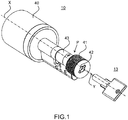
- FIG. 1 schematically represents a locking mechanism 10 and an identification key 13 adapted to implement the invention.
- the locking mechanism 10 comprises a cylinder 43 intended to be inserted into the door, a handle 40 intended to be placed inside a room to actuate the locking mechanism, thus enabling to open or close the door in the unlocked state.
- the locking mechanism comprises a front part 41 positioned outside the room. This front part 41 comprises an aperture 42 intended to receive the identification key 13.
- the aperture 42 and the outer part of the identification key 13 have a complementary form, but the outer part of the identification key 13 may also be loose in the aperture 42.
- the locking mechanism 10 may extend according to a longitudinal axis X.
- the locking mechanism may be configured so that the identification key 13 is to be inserted through the aperture 42 according to a first axis Y.
- the first axis Y may be parallel to the longitudinal axis X, but it may also be secant.
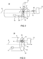
- FIG. 2 schematically represents a first embodiment of a locking mechanism 10 according to the invention.
- the locking mechanism 10 is configured to switch from a locked state to an unlocked state.
- the locking mechanism 10 comprises a processor 11 configured to read an identification code 12 of an identification key 13 and configured to cause the locking mechanism 10 to switch from the locked state to the unlocked state if the identification code 12 of the identification key 13 is an authorized code of the locking mechanism 10.
- the locking mechanism 10 comprises a printed circuit board 14 in a first plane P comprising an aperture 15 configured to accept insertion of the identification key 13 according to a first axis Y secant to the printed circuit board 14, the identification key 13 comprising a NFC passive part 16.
- the locking mechanism 10 further comprises a NFC active part 17 comprising a wire antenna 18 positioned on the printed circuit board 14, the wire antenna 18 comprising a first at least one winding 19 around the aperture 15, the wire antenna 18 being connected to the processor 11.
- the locking mechanism is configured to establish a NFC communication between the NFC active part 17 of the locking mechanism and the NFC passive part 16 of the identification key 13 when the identification key 13 is inserted into the aperture 15.
- the first axis Y is substantially perpendicular to the printed circuit board 14.
- FIG 3 schematically represents a detailed view of an embodiment of a locking mechanism 10 according to the invention.
- the identification 13 is inserted through the aperture 15 of the printed circuit board 14.
- the passive part 16 of the identification key 13 is positioned in the vicinity of the aperture 15.
- the winding 19 of the wire antenna 18 of the NFC active part 17 is around the NFC passive part 16 of the identification key 13. Thanks to this relative position between the NFC active part 17 of the locking mechanism 10 and the NFC passive part 16 of the identification key 13, the NFC passive part 16 can communicate the identification code 12 of the identification key 13 to the NFC active part 17 of the locking mechanism 10.
- the processor 11 of the locking mechanism 10 is able to determine whether the identification code 12 is an authorized code for the locking mechanism 10.
- the NFC reader (NFC active part 17) and the NFC tag (NFC passive part 16) antenna are not parallel and put on each other to operate.
- the NFC passive part 16 goes through the wire antenna 18 of the NFC active part 17.
- the relative movement between the NFC reader and the NFC tag is a translation from one part along the other part.
- the NFC passive part 16 is in the identification key 13 and the NFC active part 17 is in the locking mechanism 10, but the invention would apply inversely in a similar manner. More generally, the invention relies on the relative movement between the reader and the tag, by inserting the tag through the windings of the antenna of the reader, to provide the tag with energy and transfer information from the identification key 13 to the locking mechanism 10.
- the invention also relates to an identification key 13.
- the identification key 13 is configured to cooperate with the locking mechanism 10, configured to switch from a locked state to an unlocked state.
- the locking mechanism 10 comprises the elements mentioned before: a processor 11 configured to read an identification code 12 of the identification key 13 and configured to cause the locking mechanism 10 to switch from the locked state to the unlocked state if the identification code 12 of the identification key 13 is an authorized code of the locking mechanism 10, a printed circuit board 14 in a first plane P comprising an aperture 15 configured to accept insertion of the identification key 13 according to a first axis Y secant to the printed circuit board 14, a NFC active part 17 comprising a wire antenna 18 positioned on the printed circuit board 14, the wire antenna 18 comprising a first at least one winding 19 around the aperture 15, the wire antenna 18 being connected to the processor 11.
- the identification key 13 comprises a NFC passive part 16.
- the identification key 13 of the invention is adapted to be inserted into the aperture 15, thereby establishing a NFC communication between the NFC active part 17 of the
- the NFC passive part 16 of the identification key 13 comprises a wire antenna 32 and a chip 33 connected to the wire antenna 32 and configured to store the identification code 12.
- the NFC passive part 16 of the identification key 13 comprises a core 31 around which the wire antenna 32 is wounded, preferably a ferrite core.
- the wire antenna 32 of the NFC passive part 16 is configured to provide the chip 33 with energy when the NFC active part 17 of the locking mechanism 10 generates a magnetic field.
- This tag may take the shape of a cylinder with a copper coil rolled around the ferrite core.
- the antenna may for example (and in a non-limitating way) a 12 mm length.
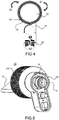
- Figure 4 schematically represents a printed circuit board 14 and a wire antenna 18 of the NFC active part of a locking mechanism 10 according to the invention.
- the wire antenna 18 may comprise at least one winding 19 around the aperture 15.
- the wire antenna 18 comprise three windings 19 around the aperture 15. It means that the wire antenna 18 makes three windings around the aperture 15 of the printed circuit board 14.
- the number of windings around the aperture is at least one and may be two, three, or even more. It constitutes a coil.
- the wire antenna 18 is for example a copper track.
- the wire antenna 18 of the NFC active part 17 may comprise a second at least one winding 19 around the aperture 15.
- the first at least one winding is positioned on a first side 21 of the printed circuit board 14 and the second at least one winding 19 is positioned on a second side 22 of the printed circuit board 14, opposite to the first side 21, and/or the wire antenna 18 of the NFC active part 17 comprises at least a third at least one winding 19 around the aperture 15, the third at least one winding 19 being positioned inside the printed circuit board 14.
- the number of windings around the aperture and the number of coils formed influence the level of the magnetic field between the NFC parts.
- the locking mechanism 10 comprises a battery 23 configured to provide the NFC active part 17 with energy.
- the identification key 13 and its tag can be inserted into the locking mechanism, as usual. At the same time, thanks to the positioning of the printed circuit board 14 and its aperture 15, the identification key 13 and its tag is thus inserted in the aperture 15 of the printed circuit board 14 within the antenna 18, thus enabling the highest radiated emission of the reader's antenna as to power the tag and to enable a reliable communication between the NFC reader and NFC tag.
- the wire antenna 18 of the NFC active part 17 is configured to generate a magnetic field when the NFC active part 17 is provided with energy, thereby providing energy to the NFC passive part 16 of the identification key 13.
- the NFC active part 17 may be for example wakened up every 300 ms in order to check if a NFC passive part is in its vicinity.
- the NFC active part activates the RF for a very short time and compares the field data from the one saved in the last wake-up. If the data has been modified, the NFC active part considers that a NFC passive part is in its vicinity. In this case, the NFC active part is fully powered by the battery 23 in order to start the communication with the NFC passive part.
- the processor 11 of the locking mechanism 10 advantageously comprises an algorithm of asymmetrical cryptography configured to verify that the identification code 12 is an authorized code of the locking mechanism 10.
- the locking mechanism 10 may comprise the Mifare Desfire EV2 tag from NXP. This tag is considered as one of the most secure one. It has an AES128 hardware cryptographic engine and is Common Criteria EAL5+ security certified by the ANSSI. Such a cryptographic engine requires many calculations. It results that the locking mechanism requires more energy to operate.
- the invention is described in a non-limitative example of a tag sending data to the reader, but the invention applies similarly to a tag that can receive data from the reader.
- the invention uses the Mifare Desfire EV2 chip from NXP, it is possible to create applications on the tag that interact with the reader to complete the full secure authentication.
- the invention applies to a NFC active part and a NFC passive part that can communicate a large variety of information, that is to say not only a command to open/close a door.
- the printed circuit board 14 may comprise a matching RF circuit 24.
- the RF matching circuit 24 enables an optimal communication link with a tag inserted in the metallic part of the locking mechanism 10. It is designed to enable a highly secure cryptographic exchange protocol with the identification key 13. In addition, it ensures the lowest power consumption for a reliable communication link.
- the matching circuit 24 is placed in the printed circuit board 14, i.e. on the same printed circuit board where the antenna 18 is placed, so as to avoid that the flex printed circuit board connecting the NFC antenna to the NFC read acts like an antenna. Furthermore the RF matching circuit 24 contributes to reduce metal impact on the antenna characteristics and the NFC communication.
- Figure 5 schematically represents the rear part of a locking mechanism 10 according to the invention. It should be kept in mind that the NFC active part 17 of the locking mechanism 10 and its wire antenna 18 are installed in a metallic environment 50 that prevents the radio waves from radiating properly. All the radiation lines going through the metallic part are attenuated and scattered.
- the printed circuit board 14 is positioned in the first plane P.
- the printed circuit board 14 may have the same form as the cylinder of the locking mechanism 10, so as to fit within the metallic environment 50 without any hand soldering.
- the wire antenna 18 may have a 260,78 mm length with 6 spires placed on both sides 21, 22 of the printed circuit board 14.
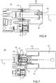
- Figure 6 schematically represents a cut view of the locking mechanism 10 according to the invention and figure 7 schematically represents a cut view of the locking mechanism 10 with an inserted identification key 13 according to the invention.
- the NFC passive part 16 of the identification key 13 comprises a wire antenna 32 and a chip 33 connected to the wire antenna 32 and configured to store the identification code 12.
- the NFC passive part 16 of the identification key 13 comprises a core 31 around which the wire antenna 32 is wounded, preferably a ferrite core.
- the wire antenna 32 of the NFC passive part 16 is configured to provide the chip 33 with energy when the NFC active part 17 generates a magnetic field.
- the front part 41 of the locking mechanism 10 is the outdoor part 52 of the locking mechanism.
- the aperture 42 of the locking mechanism 10 is in this front part 41 and is dedicated to the introduction of the outer part of the identification key 13.
- the battery 23 of the locking mechanism 10 provides the NFC active part 17 with energy. Following this, the wire antenna 18 of the NFC active part 17 generates a magnetic field. This magnetic field has a high level in the middle of the wounded antenna 18, where the wire antenna 32 of the NFC passive part 16 is inserted. It results in an energy supply to the NFC passive part 16 of the identification key 13.
- the chip 33 of the identification key 13 is now supplied with energy and can transfer data (such as its identification code 12) to the locking mechanism 10.
- Figure 8 represents a block diagram of the steps of a method for establishing a NFC communication between a NFC active part 17 of a locking mechanism 10 and a NFC passive part 16 of an identification key 13 according to the invention.
- the locking mechanism 10 is configured to switch from a locked state to an unlocked state, said locking mechanism 10 comprising a processor 11 configured to read an identification code 12 of the identification key 13 and configured to cause the locking mechanism 10 to switch from the locked state to the unlocked state if the identification code 12 of the identification key 13 is an authorized code of the locking mechanism 10, a printed circuit board 14 in a first plane comprising an aperture 15 configured to accept insertion of the identification key 13 according to a first axis Y secant to the printed circuit board 14, and a NFC active part 17 comprising a wire antenna 18 positioned on the printed circuit board 14, the wire antenna 18 comprising a first at least one winding 19 around the aperture 15, the wire antenna 18 being connected to the processor 11, the identification key 13 comprising a NFC passive part 16.
- the method of the invention comprises the
- the NFC passive part 16 of the identification key 13 may comprise a core 31, preferably a ferrite core, a wire antenna 32, preferably around the ferrite core, a chip 33 connected to the wire antenna 32 and configured to store the identification code 12.
- the step 102 of establishing the NFC communication between the NFC active part 17 of the locking mechanism 10 and the NFC passive part 16 of the identification key 13 comprises the steps of generating (step 103) a magnetic field by the wire antenna 18 of the NFC active part 17, thereby providing energy to the NFC passive part 16 of the identification key 13, i.e. powering up the NFC passive part 16, and providing (step 104) the chip 33 with energy by the wire antenna 32 of the NFC passive part 16.
- the step 103 of generating a magnetic field may be preceded by a step 107 of detecting the identification key 13.
- the method of the invention may further comprise the steps of sending (step 105) an identification code 12 from the chip 33 of the NFC passive part 16 to the NFC active part 17; and determining (step 106) by the processor 11 of the locking mechanism 10 whether the identification code 12 sent from the chip 33 is an authorized code.
Landscapes
- Physics & Mathematics (AREA)
- General Physics & Mathematics (AREA)
- Engineering & Computer Science (AREA)
- Computer Networks & Wireless Communication (AREA)
- Manufacturing & Machinery (AREA)
- Signal Processing (AREA)
- Lock And Its Accessories (AREA)
Abstract
Description
- The invention relates to the field of secure key control and concerns a locking mechanism operating with a NFC system and configured to switch between a locked state and an unlocked state.
- Electromechanical lock and key with identification code are widespread. They enable authorized key holders to have access to locked rooms if the identification code of the key corresponds to a predetermined code in relation with the electromechanical lock. The key may be an ordinary looking key to insert into the lock.
- The electromechanical lock comprises a processor configured to compare the identification code of the key with the predetermined code. If the identification code corresponds to the predetermined code, the electromechanical lock switches from its locked state to its unlocked state.
- Commonly locks, also called locking mechanisms, are formed with a body that can be easily unscrewed by a locksmith to facilitate rekeying. The body has the function to lock and unlock the lock. A lock body may be found under the form of a European cylinder (defined by the DIN18251). A European cylinder is a type of lock cylinder. There exist other profiles of lock bodies like the oval cylinder that is used in the Nordic countries. A body may not be in the form of a cylinder. A lock body may be inserted into a lock or a mortise lock or a slot-in lock. This function offers the advantage of allowing its change without altering the boltwork hardware. Removing the body typically requires only loosening a set screw, then sliding the body from the boltwork.
- The smart locking mechanism comprises an interface configured to receive an identification code from an identification key. The identification key communicates with the locking mechanism using a NFC system or another RF technology that uses a passive device. NFC stands for Near Field Communication. It is a wireless technology for near field applications. In general NFC is used to communicate within a 5 centimeters distance using the 13,56 MHz frequency. The NFC system comprises an active part, called the reader, and a passive part, called the tag. When operating, the reader generates an initial 13,56 MHz signal. If powerful enough, this signal powers up the tag and a communication link is activated between the reader and the tag.
- NFC systems are used in a large variety of applications such as pay by phone, contactless payment with the credit card, building access badge, etc. In these applications, the tag and its antenna are flat, and the antennas used with the reader are also flat. When provided with energy, the chip of the tag sends data to the reader. The tag may also receive data from the reader. And more generally the tag may communicate any kind of information. There is a communication between the active and the passive part.
- When used within a locking mechanism, the tag is positioned within the identification key and the reader is positioned within the locking mechanism. If the communication between the tag and the reader, i.e. between the key and the lock mechanism, is successful, the locking mechanism is unlocked, thus enabling the user to open/close the door.
- More precisely the tag comprises an antenna and a chip and operates as follows: the magnetic radiations from the reader antenna provides the tag with energy via the tag antenna. Being fed with energy, the chip of the tag sends data to the reader. If the data sent from the tag to the reader are in agreement with the data expected from the reader, the identification key is recognized as an authorized one and the reader sends an authorization signal to the processor of the locking mechanism to unlock the door. It is to be noticed that the tag may also receive data from the reader, and/or may communicate any kind of information.
- In order to ensure a high level of security of the locking mechanism, the tag is equipped with a hardware cryptographic engine. It results that the tag requires a lot of energy to run its cryptographic hardware. Additionally, the tag must fit in the identification key, which is very similar to an ordinary looking key. It means that the tag diameter should not exceed 5 millimeters and the tag length should be less than 12 millimeters. Last but not least, the locking mechanism into which the reader and its antenna are installed may comprise a metallic body and metallic parts, typically the key hole into which the identification key is to be inserted. The metallic parts prevent the radio waves from radiating properly. The radiation lines going through these zones are attenuated and scattered, thereby leading to a decrease of the energy at the disposal of the tag to operate.
- There is consequently a need for establishing a connection between the active part and the passive part of a NFC system to transmit information, identification, software updates, etc. In the field of locking mechanism, there is a need for a smart locking mechanism configured to switch from a locked state to an unlocked state, based on the communication of an identification code between the locking mechanism and an authorized identification key using the NFC system, which ensures a high level of security with a complex cryptography with a low power consumption while solving the integration problems related to the small dimensions of the lock mechanism. The identification key enables the authentication with the lock. Therefore, the user can unlock the door, or lock it. It enables also all type of communication between the tag and the door.
- The proposed solution to overcome this drawback is a locking mechanism with the establishment of NFC communication between the locking mechanism and the identification key, with a particular cooperation of the NFC passive part of the key and the NFC active part of the locking mechanism.
- To this end, the subject of the invention is a locking mechanism configured to switch from a locked state to an unlocked state, comprising:
- a. a processor configured to read an identification code of an identification key and configured to cause the locking mechanism to switch from the locked state to the unlocked state if the identification code of the identification key is an authorized code of the locking mechanism,
- b. a printed circuit board in a first plane comprising an aperture configured to accept insertion of the identification key according to a first axis secant to the printed circuit board, the identification key comprising a NFC passive part,
- c. a NFC active part comprising a wire antenna positioned on the printed circuit board, the wire antenna comprising a first at least one winding around the aperture, the wire antenna being connected to the processor,
- According to one aspect of the invention, the wire antenna of the NFC active part comprises a second at least one winding around the aperture, the first at least one winding being positioned on a first side of the printed circuit board and the second at least one winding being positioned on a second side of the printed circuit board, opposite to the first side, and/or the wire antenna of the NFC active part comprises at least a third at least one winding around the aperture, the third at least one winding being positioned inside the printed circuit board.
- Advantageously, the first axis is substantially perpendicular to the printed circuit board.
- Advantageously, the locking mechanism of the invention may comprise a battery configured to provide the NFC active part with energy.
- Advantageously, the wire antenna of the NFC active part is configured to generate a magnetic field when the NFC active part is provided with energy, thereby providing energy to the NFC passive part of the identification key.
- Advantageously, the NFC passive part of the identification key comprises a wire antenna, a chip connected to the wire antenna and configured to store the identification code.
- Advantageously, the NFC passive part of the identification key comprises a core around which the wire antenna is wounded, preferably a ferrite core.
- Advantageously, the wire antenna of the NFC passive part is configured to provide the chip with energy when the NFC active part generates a magnetic field.
- Advantageously, the processor comprises an algorithm of asymmetrical cryptography configured to verify that the identification code is an authorized code of the locking mechanism.
- The invention also concerns an identification key configured to cooperate with a locking mechanism, configured to switch from a locked state to an unlocked state, said locking mechanism comprising:
- a. a processor configured to read an identification code of the identification key and configured to cause the locking mechanism to switch from the locked state to the unlocked state if the identification code of the identification key is an authorized code of the locking mechanism,
- b. a printed circuit board in a first plane comprising an aperture configured to accept insertion of the identification key according to a first axis secant to the printed circuit board,
- c. a NFC active part comprising a wire antenna positioned on the printed circuit board, the wire antenna comprising a first at least one winding around the aperture, the wire antenna being connected to the processor,
- Advantageously, the NFC passive part of the identification key comprises a wire antenna, a chip connected to the wire antenna and configured to store the identification code.
- Advantageously, the NFC passive part of the identification key comprises a core around which the wire antenna is wounded, preferably a ferrite core.
- Advantageously, the wire antenna of the NFC passive part is configured to provide the chip with energy when the NFC active part of the locking mechanism generates a magnetic field.
- The invention also concerns an identification key configured to cooperate with a locking set comprising such a locking mechanism and such an identification key.
- The invention also concerns a method for establishing a NFC communication between a NFC active part of a locking mechanism and a NFC passive part of an identification key, the locking mechanism configured to switch from a locked state to an unlocked state, said locking mechanism comprising a processor configured to read an identification code of the identification key and configured to cause the locking mechanism to switch from the locked state to the unlocked state if the identification code of the identification key is an authorized code of the locking mechanism, a printed circuit board in a first plane comprising an aperture configured to accept insertion of the identification key according to a first axis secant to the printed circuit board, and a NFC active part comprising a wire antenna positioned on the printed circuit board, the wire antenna comprising a first at least one winding around the aperture, the wire antenna being connected to the processor, the identification key comprising a NFC passive part, said method comprising the steps of:
- a. inserting the identification key into the aperture;
- b. establishing a NFC communication between the NFC active part of the locking mechanism and the NFC passive part of the identification key.
- Advantageously, the NFC passive part of the identification key comprising a wire antenna, a chip connected to the wire antenna and configured to store the identification code, wherein the step of establishing the NFC communication between the NFC active part of the locking mechanism and the NFC passive part of the identification key comprises the steps of:
- a. generating a magnetic field by the wire antenna of the NFC active part, thereby providing energy to the NFC passive part of the identification key;
- b. providing the chip with energy by the wire antenna of the NFC passive part.
- Advantageously, the method of the invention further comprises the steps of sending an identification code from the chip of the NFC passive part to the NFC active part, determining by the processor of the locking mechanism whether the identification code sent from the chip is an authorized code.
- The accompanying drawings illustrate various non-limiting, example, innovative aspects in accordance with the present descriptions:
-
Figure 1 schematically represents a locking mechanism and an identification key adapted to implement the invention; -
Figure 2 schematically represents a first embodiment of a locking mechanism according to the invention; -
Figure 3 schematically represents a detailed view of an embodiment of a locking mechanism according to the invention; -
Figure 4 schematically represents a printed circuit board and a wire antenna of the NFC active part of a locking mechanism according to the invention; -
Figure 5 schematically represents the rear part of a locking mechanism according to the invention; -
Figure 6 schematically represents a cut view of the locking mechanism according to the invention; -
Figure 7 schematically represents a cut view of the locking mechanism with an inserted identification key according to the invention; -
Figure 8 represents a block diagram of the steps of a method for establishing a NFC communication between a NFC active part of a locking mechanism and a NFC passive part of an identification key according to the invention. - For the sake of clarity, the same elements have the same references in the various figures.
- Although many of the features of this invention are described in relation to a door, it is understood that they are generally applicable to any opening unit, such as a window. Moreover, these features are also applicable to many other devices, for example a padlock, having a locked state and an unlocked state.
- In order to illustrate the invention, the explanations are related to a door. Note that these explanations may be applied similarly to any opening unit. A door is an opening unit enabling the access to a room (or from a room to the outside) through an aperture. The door is connected to a door frame that frames the aperture and is fixed to the walls around the aperture. In an unlocked state of the door, the door is mobile in relation to the door frame, typically mobile in rotation around doors hinges (or in translation in the case the door and the door frame are configured to let the door slide through a part of the door frame and into the wall). The door may be in an open configuration or a closed configuration. In the closed configuration, the door covers the aperture (i.e. no one can go through the aperture). Typically the door is equipped with a lock mechanism. The lock mechanism has a latch that is either inserted into a slot of the door frame (the door is closed) or retracted inside the door (the door is no longer attached to the door frame and may be open). In the closed configuration, the latch is inserted into the slot of the door frame. In existing lock mechanisms, a lock clutch is connected to the latch. The lock clutch is usually engaged with both the indoor and outdoor door knobs. This enables a user to activate the lock clutch to make the latch move by moving one of the door knobs. Therefore a user has to move a door knob of the door to switch from the closed configuration of the door to the open configuration of the door. Indeed, the lock clutch being engaged with the knob, the movement of the knob leads to the movement of the latch. Moving the door knob makes the latch retract into the door. The user can pull or push the door to open it.
- In the closed configuration of the door, the lock mechanism can be either in a locked state or an unlocked state. The unlocked state corresponds to the case discussed above. The door may be open by a user when activating a door knob and pushing or pulling the door. More precisely, the lock mechanism has a deadbolt entirely positioned inside the locking mechanism in the unlocked state. In the locked state, this deadbolt projects beyond the lock mechanism and is inserted into a slot of the door frame, thus locking the door to the frame. The movement of the deadbolt can be mechanically obtained, for example by a rotation of a key inserted into the locking mechanism. The rotation of the key clockwise, respectively anticlockwise, causes the deadbolt to translate either outside the lock mechanism to be inserted into the slot of the door frame, or inside the lock mechanism. To switch from the locked state of the door to the unlocked state of the door, a user has to rotate the key with the corresponding rotation of the key inside the lock mechanism. As an alternative to a rotation of the key, the lock mechanism may be unlocked by an authorized identification key. It is for example possible to authenticate with a smartphone (with BLE - Bluetooth Low Energy-) in addition to the key. But the user will have to rotate with his/her hand the outside handle of the lock and rotate with the corresponding rotation exactly the same way as if the user was using a key. Indeed, once authenticate the motor moves and enables the user to move the deadlock. Then the user can move the deadlock in the way he/she wants. When it is identified in the vicinity of the lock mechanism, the authorized identification key may activate a motor in the lock mechanism that causes the deadbolt to translate. More precisely the motor can only enable the user to move the deadbolt using the key or the outside handle. Then, to open the door, the user turns a door knob or pushes a door handle of the door, as explained before. In other words, the locked state corresponds to the fact that the user cannot action the door (i.e. open it or close it).
- These explanations are intended to understand the meaning of the wording of locked state and unlocked state of the locking mechanism used in the description.
-
Figure 1 schematically represents alocking mechanism 10 and an identification key 13 adapted to implement the invention. Thelocking mechanism 10 comprises acylinder 43 intended to be inserted into the door, ahandle 40 intended to be placed inside a room to actuate the locking mechanism, thus enabling to open or close the door in the unlocked state. The locking mechanism comprises afront part 41 positioned outside the room. Thisfront part 41 comprises anaperture 42 intended to receive theidentification key 13. Advantageously, theaperture 42 and the outer part of theidentification key 13 have a complementary form, but the outer part of theidentification key 13 may also be loose in theaperture 42. Thelocking mechanism 10 may extend according to a longitudinal axis X. The locking mechanism may be configured so that theidentification key 13 is to be inserted through theaperture 42 according to a first axis Y. The first axis Y may be parallel to the longitudinal axis X, but it may also be secant. -
Figure 2 schematically represents a first embodiment of alocking mechanism 10 according to the invention. Thelocking mechanism 10 is configured to switch from a locked state to an unlocked state. Thelocking mechanism 10 comprises aprocessor 11 configured to read anidentification code 12 of anidentification key 13 and configured to cause thelocking mechanism 10 to switch from the locked state to the unlocked state if theidentification code 12 of theidentification key 13 is an authorized code of thelocking mechanism 10. Thelocking mechanism 10 comprises a printedcircuit board 14 in a first plane P comprising anaperture 15 configured to accept insertion of the identification key 13 according to a first axis Y secant to the printedcircuit board 14, theidentification key 13 comprising a NFCpassive part 16. Thelocking mechanism 10 further comprises a NFCactive part 17 comprising awire antenna 18 positioned on the printedcircuit board 14, thewire antenna 18 comprising a first at least one winding 19 around theaperture 15, thewire antenna 18 being connected to theprocessor 11. According to the invention, the locking mechanism is configured to establish a NFC communication between the NFCactive part 17 of the locking mechanism and the NFCpassive part 16 of theidentification key 13 when theidentification key 13 is inserted into theaperture 15. - In a preferred embodiment of the
locking mechanism 10, the first axis Y is substantially perpendicular to the printedcircuit board 14. -
Figure 3 schematically represents a detailed view of an embodiment of alocking mechanism 10 according to the invention. Theidentification 13 is inserted through theaperture 15 of the printedcircuit board 14. Thepassive part 16 of theidentification key 13 is positioned in the vicinity of theaperture 15. In other words, the winding 19 of thewire antenna 18 of the NFCactive part 17 is around the NFCpassive part 16 of theidentification key 13. Thanks to this relative position between the NFCactive part 17 of thelocking mechanism 10 and the NFCpassive part 16 of theidentification key 13, the NFCpassive part 16 can communicate theidentification code 12 of the identification key 13 to the NFCactive part 17 of thelocking mechanism 10. Theprocessor 11 of thelocking mechanism 10 is able to determine whether theidentification code 12 is an authorized code for thelocking mechanism 10. - Contrary to usual NFC application, the NFC reader (NFC active part 17) and the NFC tag (NFC passive part 16) antenna are not parallel and put on each other to operate. In the invention, the NFC
passive part 16 goes through thewire antenna 18 of the NFCactive part 17. The relative movement between the NFC reader and the NFC tag is a translation from one part along the other part. - Due to the dimension constraints, the NFC
passive part 16 is in theidentification key 13 and the NFCactive part 17 is in thelocking mechanism 10, but the invention would apply inversely in a similar manner. More generally, the invention relies on the relative movement between the reader and the tag, by inserting the tag through the windings of the antenna of the reader, to provide the tag with energy and transfer information from the identification key 13 to thelocking mechanism 10. - The invention also relates to an
identification key 13. Theidentification key 13 is configured to cooperate with thelocking mechanism 10, configured to switch from a locked state to an unlocked state. Thelocking mechanism 10 comprises the elements mentioned before: aprocessor 11 configured to read anidentification code 12 of theidentification key 13 and configured to cause thelocking mechanism 10 to switch from the locked state to the unlocked state if theidentification code 12 of theidentification key 13 is an authorized code of thelocking mechanism 10, a printedcircuit board 14 in a first plane P comprising anaperture 15 configured to accept insertion of the identification key 13 according to a first axis Y secant to the printedcircuit board 14, a NFCactive part 17 comprising awire antenna 18 positioned on the printedcircuit board 14, thewire antenna 18 comprising a first at least one winding 19 around theaperture 15, thewire antenna 18 being connected to theprocessor 11. Theidentification key 13 comprises a NFCpassive part 16. Theidentification key 13 of the invention is adapted to be inserted into theaperture 15, thereby establishing a NFC communication between the NFCactive part 17 of thelocking mechanism 10 and the NFCpassive part 16 of theidentification key 13. - As shown in
Figure 7 , the NFCpassive part 16 of theidentification key 13 comprises awire antenna 32 and achip 33 connected to thewire antenna 32 and configured to store theidentification code 12. - Advantageously, the NFC
passive part 16 of theidentification key 13 comprises acore 31 around which thewire antenna 32 is wounded, preferably a ferrite core. - The
wire antenna 32 of the NFCpassive part 16 is configured to provide thechip 33 with energy when the NFCactive part 17 of thelocking mechanism 10 generates a magnetic field. - Such a design enables that the NFC tag can be fitted within the
identification key 13. This tag may take the shape of a cylinder with a copper coil rolled around the ferrite core. The antenna may for example (and in a non-limitating way) a 12 mm length. - The cooperation between the NFC
active part 17 of thelocking mechanism 10 and the NFCpassive part 16 of theidentification key 13 will appear more clearly with the description of the following figures. -
Figure 4 schematically represents a printedcircuit board 14 and awire antenna 18 of the NFC active part of alocking mechanism 10 according to the invention. As mentioned before, thewire antenna 18 may comprise at least one winding 19 around theaperture 15. As depicted in the figure, thewire antenna 18 comprise threewindings 19 around theaperture 15. It means that thewire antenna 18 makes three windings around theaperture 15 of the printedcircuit board 14. The number of windings around the aperture is at least one and may be two, three, or even more. It constitutes a coil. Thewire antenna 18 is for example a copper track. - The
wire antenna 18 of the NFCactive part 17 may comprise a second at least one winding 19 around theaperture 15. The first at least one winding is positioned on afirst side 21 of the printedcircuit board 14 and the second at least one winding 19 is positioned on asecond side 22 of the printedcircuit board 14, opposite to thefirst side 21, and/or thewire antenna 18 of the NFCactive part 17 comprises at least a third at least one winding 19 around theaperture 15, the third at least one winding 19 being positioned inside the printedcircuit board 14. The number of windings around the aperture and the number of coils formed (i.e. one on each side of the printed circuit board and inside the printed circuit board) influence the level of the magnetic field between the NFC parts. - The
locking mechanism 10 comprises abattery 23 configured to provide the NFCactive part 17 with energy. - The
identification key 13 and its tag can be inserted into the locking mechanism, as usual. At the same time, thanks to the positioning of the printedcircuit board 14 and itsaperture 15, theidentification key 13 and its tag is thus inserted in theaperture 15 of the printedcircuit board 14 within theantenna 18, thus enabling the highest radiated emission of the reader's antenna as to power the tag and to enable a reliable communication between the NFC reader and NFC tag. - More precisely, once provided with energy, the
wire antenna 18 of the NFCactive part 17 is configured to generate a magnetic field when the NFCactive part 17 is provided with energy, thereby providing energy to the NFCpassive part 16 of theidentification key 13. The NFCactive part 17 may be for example wakened up every 300 ms in order to check if a NFC passive part is in its vicinity. When wakened, the NFC active part activates the RF for a very short time and compares the field data from the one saved in the last wake-up. If the data has been modified, the NFC active part considers that a NFC passive part is in its vicinity. In this case, the NFC active part is fully powered by thebattery 23 in order to start the communication with the NFC passive part. - The
processor 11 of thelocking mechanism 10 advantageously comprises an algorithm of asymmetrical cryptography configured to verify that theidentification code 12 is an authorized code of thelocking mechanism 10. For example thelocking mechanism 10 may comprise the Mifare Desfire EV2 tag from NXP. This tag is considered as one of the most secure one. It has an AES128 hardware cryptographic engine and is Common Criteria EAL5+ security certified by the ANSSI. Such a cryptographic engine requires many calculations. It results that the locking mechanism requires more energy to operate. - It is to be noted that the invention is described in a non-limitative example of a tag sending data to the reader, but the invention applies similarly to a tag that can receive data from the reader. In the cited example, using the Mifare Desfire EV2 chip from NXP, it is possible to create applications on the tag that interact with the reader to complete the full secure authentication. The invention applies to a NFC active part and a NFC passive part that can communicate a large variety of information, that is to say not only a command to open/close a door.
- The printed
circuit board 14 may comprise a matchingRF circuit 24. TheRF matching circuit 24 enables an optimal communication link with a tag inserted in the metallic part of thelocking mechanism 10. It is designed to enable a highly secure cryptographic exchange protocol with theidentification key 13. In addition, it ensures the lowest power consumption for a reliable communication link. The matchingcircuit 24 is placed in the printedcircuit board 14, i.e. on the same printed circuit board where theantenna 18 is placed, so as to avoid that the flex printed circuit board connecting the NFC antenna to the NFC read acts like an antenna. Furthermore theRF matching circuit 24 contributes to reduce metal impact on the antenna characteristics and the NFC communication. -
Figure 5 schematically represents the rear part of alocking mechanism 10 according to the invention. It should be kept in mind that the NFCactive part 17 of thelocking mechanism 10 and itswire antenna 18 are installed in ametallic environment 50 that prevents the radio waves from radiating properly. All the radiation lines going through the metallic part are attenuated and scattered. - The printed
circuit board 14 is positioned in the first plane P. As represented infigure 4 , the printedcircuit board 14 may have the same form as the cylinder of thelocking mechanism 10, so as to fit within themetallic environment 50 without any hand soldering. As an example and in a non-limitative way, thewire antenna 18 may have a 260,78 mm length with 6 spires placed on bothsides circuit board 14. -
Figure 6 schematically represents a cut view of thelocking mechanism 10 according to the invention andfigure 7 schematically represents a cut view of thelocking mechanism 10 with an inserted identification key 13 according to the invention. - The NFC
passive part 16 of theidentification key 13 comprises awire antenna 32 and achip 33 connected to thewire antenna 32 and configured to store theidentification code 12. The NFCpassive part 16 of theidentification key 13 comprises acore 31 around which thewire antenna 32 is wounded, preferably a ferrite core. - The
wire antenna 32 of the NFCpassive part 16 is configured to provide thechip 33 with energy when the NFCactive part 17 generates a magnetic field. - The
front part 41 of thelocking mechanism 10 is theoutdoor part 52 of the locking mechanism. Theaperture 42 of thelocking mechanism 10 is in thisfront part 41 and is dedicated to the introduction of the outer part of theidentification key 13. - The
battery 23 of thelocking mechanism 10 provides the NFCactive part 17 with energy. Following this, thewire antenna 18 of the NFCactive part 17 generates a magnetic field. This magnetic field has a high level in the middle of the woundedantenna 18, where thewire antenna 32 of the NFCpassive part 16 is inserted. It results in an energy supply to the NFCpassive part 16 of theidentification key 13. Thechip 33 of theidentification key 13 is now supplied with energy and can transfer data (such as its identification code 12) to thelocking mechanism 10. -
Figure 8 represents a block diagram of the steps of a method for establishing a NFC communication between a NFCactive part 17 of alocking mechanism 10 and a NFCpassive part 16 of an identification key 13 according to the invention. Thelocking mechanism 10 is configured to switch from a locked state to an unlocked state, saidlocking mechanism 10 comprising aprocessor 11 configured to read anidentification code 12 of theidentification key 13 and configured to cause thelocking mechanism 10 to switch from the locked state to the unlocked state if theidentification code 12 of theidentification key 13 is an authorized code of thelocking mechanism 10, a printedcircuit board 14 in a first plane comprising anaperture 15 configured to accept insertion of the identification key 13 according to a first axis Y secant to the printedcircuit board 14, and a NFCactive part 17 comprising awire antenna 18 positioned on the printedcircuit board 14, thewire antenna 18 comprising a first at least one winding 19 around theaperture 15, thewire antenna 18 being connected to theprocessor 11, theidentification key 13 comprising a NFCpassive part 16. The method of the invention comprises the steps of inserting (step 101) the identification key 13 into theaperture 15, establishing (step 102) a NFC communication between the NFCactive part 17 of thelocking mechanism 10 and the NFCpassive part 16 of theidentification key 13. - The NFC
passive part 16 of theidentification key 13 may comprise a core 31, preferably a ferrite core, awire antenna 32, preferably around the ferrite core, achip 33 connected to thewire antenna 32 and configured to store theidentification code 12. Thestep 102 of establishing the NFC communication between the NFCactive part 17 of thelocking mechanism 10 and the NFCpassive part 16 of theidentification key 13 comprises the steps of generating (step 103) a magnetic field by thewire antenna 18 of the NFCactive part 17, thereby providing energy to the NFCpassive part 16 of theidentification key 13, i.e. powering up the NFCpassive part 16, and providing (step 104) thechip 33 with energy by thewire antenna 32 of the NFCpassive part 16. Thestep 103 of generating a magnetic field may be preceded by astep 107 of detecting theidentification key 13. - Once the NFC communication between the locking
mechanism 10 and theidentification key 13 is established, the method of the invention may further comprise the steps of sending (step 105) anidentification code 12 from thechip 33 of the NFCpassive part 16 to the NFCactive part 17; and determining (step 106) by theprocessor 11 of thelocking mechanism 10 whether theidentification code 12 sent from thechip 33 is an authorized code. - The examples disclosed in this specification are therefore only illustrative of some embodiments of the invention and may be combined. They do not in any manner limit the scope of said invention which is defined by the appended claims.
Claims (17)
- A locking mechanism (10) configured to switch from a locked state to an unlocked state, comprising:a. a processor (11) configured to read an identification code (12) of an identification key (13) and configured to cause the locking mechanism (10) to switch from the locked state to the unlocked state if the identification code (12) of the identification key (13) is an authorized code of the locking mechanism (10),b. a printed circuit board (14) in a first plane (P) comprising an aperture (15) configured to accept insertion of the identification key (13) according to a first axis (Y) secant to the printed circuit board (14), the identification key (13) comprising a NFC passive part (16),c. a NFC active part (17) comprising a wire antenna (18) positioned on the printed circuit board (14), the wire antenna (18) comprising a first at least one winding (19) around the aperture (15), the wire antenna (18) being connected to the processor (11),wherein the locking mechanism is configured to establish a NFC communication between the NFC active part (17) of the locking mechanism and the NFC passive part (16) of the identification key (13) when the identification key (13) is inserted into the aperture (15).
- The locking mechanism (10) of claim 1, wherein the wire antenna (18) of the NFC active part (17) comprises a second at least one winding (19) around the aperture (15), the first at least one winding being positioned on a first side (21) of the printed circuit board (14) and the second at least one winding (19) being positioned on a second side (22) of the printed circuit board (14), opposite to the first side (21), and/or the wire antenna (18) of the NFC active part (17) comprises at least a third at least one winding (19) around the aperture (15), the third at least one winding (19) being positioned inside the printed circuit board (14).
- The locking mechanism (10) of claim 1 or 2, wherein the first axis (Y) is substantially perpendicular to the printed circuit board (14).
- The locking mechanism (10) of any one of claims 1 to 3, comprising a battery (23) configured to provide the NFC active part (17) with energy.
- The locking mechanism (10) of claim 4, wherein the wire antenna (18) of the NFC active part (17) is configured to generate a magnetic field when the NFC active part (17) is provided with energy, thereby providing energy to the NFC passive part (16) of the identification key (13).
- The locking mechanism (10) of any one of claims 1 to 5, wherein the NFC passive part (16) of the identification key (13) comprises:a. a wire antenna (32);b. a chip (33) connected to the wire antenna (32) and configured to store the identification code (12).
- The locking mechanism (10) of claim 6, wherein the NFC passive part (16) of the identification key (13) comprises a core (31) around which the wire antenna (32) is wounded, preferably a ferrite core.
- The locking mechanism (10) of any one of claims 6 or 7, wherein the wire antenna (32) of the NFC passive part (16) is configured to provide the chip (33) with energy when the NFC active part (17) generates a magnetic field.
- The locking mechanism (10) of any one of claims 1 to 8, wherein the processor (11) comprises an algorithm of asymmetrical cryptography configured to verify that the identification code (12) is an authorized code of the locking mechanism (10).
- An identification key (13) configured to cooperate with a locking mechanism (10), configured to switch from a locked state to an unlocked state, said locking mechanism comprising:a. a processor (11) configured to read an identification code (12) of the identification key (13) and configured to cause the locking mechanism (10) to switch from the locked state to the unlocked state if the identification code (12) of the identification key (13) is an authorized code of the locking mechanism (10),b. a printed circuit board (14) in a first plane (P)comprising an aperture (15) configured to accept insertion of the identification key (13) according to a first axis (Y) secant to the printed circuit board (14),c. a NFC active part (17) comprising a wire antenna (18) positioned on the printed circuit board (14), the wire antenna (18) comprising a first at least one winding (19) around the aperture (15), the wire antenna (18) being connected to the processor (11),the identification key (13) comprising a NFC passive part (16),
wherein the identification key (13) is adapted to be inserted into the aperture (15), thereby establishing a NFC communication between the NFC active part (17) of the locking mechanism (10) and the NFC passive part (16) of the identification key (13). - The identification key (13) of claim 10, wherein the NFC passive part (16) of the identification key (13) comprises:a. a wire antenna (32);b. a chip (33) connected to the wire antenna (32) and configured to store the identification code (12).
- The identification key (13) of claim 11, wherein the NFC passive part (16) of the identification key (13) comprises a core (31) around which the wire antenna (32) is wounded, preferably a ferrite core.
- The identification key (13) of claim 10, wherein the wire antenna (32) of the NFC passive part (16) is configured to provide the chip (33) with energy when the NFC active part (17) of the locking mechanism (10) generates a magnetic field.
- A locking set (30) comprising the locking mechanism (10) of any one of claims 1 to 9 and the identification key (13) of any one of claims 10 to 13.
- A method for establishing a NFC communication between a NFC active part (17) of a locking mechanism (10) and a NFC passive part (16) of an identification key (13),
the locking mechanism (10) configured to switch from a locked state to an unlocked state, said locking mechanism (10) comprising a processor (11) configured to read an identification code (12) of the identification key (13) and configured to cause the locking mechanism (10) to switch from the locked state to the unlocked state if the identification code (12) of the identification key (13) is an authorized code of the locking mechanism (10), a printed circuit board (14) in a first plane comprising an aperture (15) configured to accept insertion of the identification key (13) according to a first axis (Y) secant to the printed circuit board (14), and a NFC active part (17) comprising a wire antenna (18) positioned on the printed circuit board (14), the wire antenna (18) comprising a first at least one winding (19) around the aperture (15), the wire antenna (18) being connected to the processor (11), the identification key (13) comprising a NFC passive part (16),
said method comprising the steps of:c. inserting (step 101) the identification key (13) into the aperture (15);d. establishing (step 102) a NFC communication between the NFC active part (17) of the locking mechanism (10) and the NFC passive part (16) of the identification key (13). - The method of claim 15, the NFC passive part (16) of the identification key (13) comprising a wire antenna (32), a chip (33) connected to the wire antenna (32) and configured to store the identification code (12), wherein the step (102) of establishing the NFC communication between the NFC active part (17) of the locking mechanism (10) and the NFC passive part (16) of the identification key (13) comprises the steps of:c. generating (step 103) a magnetic field by the wire antenna (18) of the NFC active part (17), thereby providing energy to the NFC passive part (16) of the identification key (13);d. providing (step 104) the chip (33) with energy by the wire antenna (32) of the NFC passive part (16).
- The method of claim 15 or 16, further comprising the steps of:a. sending (step 105) an identification code (12) from the chip (33) of the NFC passive part (16) to the NFC active part (17);b. determining (step 106) by the processor (11) of the locking mechanism (10) whether the identification code (12) sent from the chip (33) is an authorized code.
Priority Applications (4)
| Application Number | Priority Date | Filing Date | Title |
|---|---|---|---|
| EP19306567.9A EP3832521A1 (en) | 2019-12-04 | 2019-12-04 | Smart lock having an electromechanical key |
| CN202080080628.0A CN114868161A (en) | 2019-12-04 | 2020-11-23 | Intelligent lock with electromechanical key |
| US17/777,673 US12170394B2 (en) | 2019-12-04 | 2020-11-23 | Smart lock having an electromechanical key |
| PCT/EP2020/083052 WO2021110453A1 (en) | 2019-12-04 | 2020-11-23 | Smart lock having an electromechanical key |
Applications Claiming Priority (1)
| Application Number | Priority Date | Filing Date | Title |
|---|---|---|---|
| EP19306567.9A EP3832521A1 (en) | 2019-12-04 | 2019-12-04 | Smart lock having an electromechanical key |
Publications (1)
| Publication Number | Publication Date |
|---|---|
| EP3832521A1 true EP3832521A1 (en) | 2021-06-09 |
Family
ID=69593525
Family Applications (1)
| Application Number | Title | Priority Date | Filing Date |
|---|---|---|---|
| EP19306567.9A Pending EP3832521A1 (en) | 2019-12-04 | 2019-12-04 | Smart lock having an electromechanical key |
Country Status (4)
| Country | Link |
|---|---|
| US (1) | US12170394B2 (en) |
| EP (1) | EP3832521A1 (en) |
| CN (1) | CN114868161A (en) |
| WO (1) | WO2021110453A1 (en) |
Citations (6)
| Publication number | Priority date | Publication date | Assignee | Title |
|---|---|---|---|---|
| EP0695676A2 (en) * | 1994-06-06 | 1996-02-07 | Delco Electronics Corporation | Vehicle security system |
| US20060226948A1 (en) * | 2005-04-08 | 2006-10-12 | Computerized Security Systems | Door lock with RFID key |
| EP1717761A2 (en) * | 2005-04-25 | 2006-11-02 | CEStronics GmbH | Cylinder lock for a key storing an electronic secret code |
| EP2708681A2 (en) * | 2012-09-12 | 2014-03-19 | Aug. Winkhaus GmbH & Co. KG | Locking cylinder for an electronic key |
| JP2014203385A (en) * | 2013-04-09 | 2014-10-27 | 株式会社名岐ベンド | Management system of automatic dispenser, and management device |
| CN206337913U (en) * | 2016-12-30 | 2017-07-18 | 卓捷创芯科技(深圳)有限公司 | Based on passive radio-frequency identification labeled intelligent door lock |
Family Cites Families (15)
| Publication number | Priority date | Publication date | Assignee | Title |
|---|---|---|---|---|
| US5367295A (en) * | 1992-02-14 | 1994-11-22 | Security People, Inc. | Conventional mechanical lock cylinders and keys with electronic access control feature |
| JP3380368B2 (en) * | 1995-06-05 | 2003-02-24 | 三菱電機株式会社 | Vehicle anti-theft device |
| JPH10140900A (en) * | 1996-09-13 | 1998-05-26 | Tokai Rika Co Ltd | Immobilizer system mounting vehicle and member used for immobilizer system |
| DE19908085C1 (en) * | 1999-02-25 | 2000-06-21 | Huf Huelsbeck & Fuerst Gmbh | Device for receiving and holding an identity transmitter like an electronic key has a holding element to engage in a side notch on the identity transmitter for swiveling a sprung flap-like cover open and closed. |
| US7116214B2 (en) * | 2004-09-16 | 2006-10-03 | Lear Corporation | Circuit board assembly with integral antenna |
| EP2017794A1 (en) * | 2007-07-18 | 2009-01-21 | iLoq Oy | Electromechanical lock and key |
| DE102010061351A1 (en) * | 2010-12-20 | 2012-06-21 | Huf Hülsbeck & Fürst Gmbh & Co. Kg | Compact, NFC communication option having ID transmitter of a motor vehicle access system |
| DE112016004186T5 (en) | 2015-09-15 | 2018-05-30 | Murata Manufacturing Co., Ltd. | Key with wireless communication device and lock for key with wireless communication device |
| ITUA20163129A1 (en) | 2016-05-04 | 2017-11-04 | Guidi Francesco Srlu | WEARABLE DEVICE WITH RFID OR INTEGRATED CHIPSET |
| EP3373457A1 (en) | 2017-03-08 | 2018-09-12 | iLOQ Oy | Electromechanical lock |
| EP3506215A1 (en) | 2017-12-28 | 2019-07-03 | Netatmo | Smart lock having an electromechanical key |
| EP3506216A1 (en) * | 2017-12-28 | 2019-07-03 | Netatmo | Smart lock with power saving having an electromechanical key |
| CN108643713B (en) | 2018-04-24 | 2020-10-27 | 深圳禾苗通信科技有限公司 | Passive lock structure, passive lock and control system and method thereof |
| CN109493497A (en) | 2018-12-26 | 2019-03-19 | 无锡卓信信息科技股份有限公司 | Electronics unlocking system |
| CN110533803A (en) | 2019-07-19 | 2019-12-03 | 宁波生久柜锁有限公司 | The passive intelligent electronic lock of electricity is taken based on NFC electromagnetic field |
-
2019
- 2019-12-04 EP EP19306567.9A patent/EP3832521A1/en active Pending
-
2020
- 2020-11-23 CN CN202080080628.0A patent/CN114868161A/en active Pending
- 2020-11-23 US US17/777,673 patent/US12170394B2/en active Active
- 2020-11-23 WO PCT/EP2020/083052 patent/WO2021110453A1/en not_active Ceased
Patent Citations (6)
| Publication number | Priority date | Publication date | Assignee | Title |
|---|---|---|---|---|
| EP0695676A2 (en) * | 1994-06-06 | 1996-02-07 | Delco Electronics Corporation | Vehicle security system |
| US20060226948A1 (en) * | 2005-04-08 | 2006-10-12 | Computerized Security Systems | Door lock with RFID key |
| EP1717761A2 (en) * | 2005-04-25 | 2006-11-02 | CEStronics GmbH | Cylinder lock for a key storing an electronic secret code |
| EP2708681A2 (en) * | 2012-09-12 | 2014-03-19 | Aug. Winkhaus GmbH & Co. KG | Locking cylinder for an electronic key |
| JP2014203385A (en) * | 2013-04-09 | 2014-10-27 | 株式会社名岐ベンド | Management system of automatic dispenser, and management device |
| CN206337913U (en) * | 2016-12-30 | 2017-07-18 | 卓捷创芯科技(深圳)有限公司 | Based on passive radio-frequency identification labeled intelligent door lock |
Also Published As
| Publication number | Publication date |
|---|---|
| CN114868161A (en) | 2022-08-05 |
| US12170394B2 (en) | 2024-12-17 |
| WO2021110453A1 (en) | 2021-06-10 |
| US20230006330A1 (en) | 2023-01-05 |
Similar Documents
| Publication | Publication Date | Title |
|---|---|---|
| CA3009775C (en) | Near field communication tag | |
| EP2157552B1 (en) | Electromechanical lock | |
| CN104011776B (en) | Electromechanical lock and method for operating an electromechanical lock | |
| US20030217574A1 (en) | Lock device for a door and method of operating the lock device | |
| WO2016023020A1 (en) | Electronic locking system | |
| US20140218167A1 (en) | Wirelessly sensed and controlled locking device | |
| WO2013138791A1 (en) | Non-contact electronic door locks having specialized radio frequency beam formation | |
| CN102656331A (en) | wireless security door antenna | |
| CN104599352A (en) | Intelligent lock core, lock, blocking device, intelligent blocking system and working method of intelligent blocking system | |
| US20190206157A1 (en) | Smart lock having an electromechanical key with power saving | |
| US9747738B1 (en) | Electronic access control device | |
| US12170394B2 (en) | Smart lock having an electromechanical key | |
| EP4205090B1 (en) | Lock device based on magnet and magnetically controllable switch | |
| US12428873B2 (en) | Actuating device for lock device, and lock device | |
| EP3987133B1 (en) | Bolt identity | |
| EP3506215A1 (en) | Smart lock having an electromechanical key | |
| EP3480736B1 (en) | Electronic identification device | |
| US20240271465A1 (en) | Roll-up door lock | |
| US20240401376A1 (en) | Electronic locking system with mechanical override and keyless locking system | |
| EP3263810B1 (en) | History management system of electronic locking apparatus | |
| JP2005299264A (en) | Key device incorporating radiotag | |
| US12258787B2 (en) | Vandal-proof mechatronic lock system | |
| KR101445297B1 (en) | Wireless card key | |
| EP3505709B1 (en) | Secure smart lock | |
| JP7163042B2 (en) | door control system |
Legal Events
| Date | Code | Title | Description |
|---|---|---|---|
| PUAI | Public reference made under article 153(3) epc to a published international application that has entered the european phase |
Free format text: ORIGINAL CODE: 0009012 |
|
| STAA | Information on the status of an ep patent application or granted ep patent |
Free format text: STATUS: THE APPLICATION HAS BEEN PUBLISHED |
|
| AK | Designated contracting states |
Kind code of ref document: A1 Designated state(s): AL AT BE BG CH CY CZ DE DK EE ES FI FR GB GR HR HU IE IS IT LI LT LU LV MC MK MT NL NO PL PT RO RS SE SI SK SM TR |
|
| STAA | Information on the status of an ep patent application or granted ep patent |
Free format text: STATUS: REQUEST FOR EXAMINATION WAS MADE |
|
| 17P | Request for examination filed |
Effective date: 20211013 |
|
| RBV | Designated contracting states (corrected) |
Designated state(s): AL AT BE BG CH CY CZ DE DK EE ES FI FR GB GR HR HU IE IS IT LI LT LU LV MC MK MT NL NO PL PT RO RS SE SI SK SM TR |
|
| STAA | Information on the status of an ep patent application or granted ep patent |
Free format text: STATUS: EXAMINATION IS IN PROGRESS |
|
| 17Q | First examination report despatched |
Effective date: 20230329 |
|
| STAA | Information on the status of an ep patent application or granted ep patent |
Free format text: STATUS: THE APPLICATION IS DEEMED TO BE WITHDRAWN |