EP3832632A2 - Afficheur avec vision nocturne - Google Patents
Afficheur avec vision nocturne Download PDFInfo
- Publication number
- EP3832632A2 EP3832632A2 EP20212006.9A EP20212006A EP3832632A2 EP 3832632 A2 EP3832632 A2 EP 3832632A2 EP 20212006 A EP20212006 A EP 20212006A EP 3832632 A2 EP3832632 A2 EP 3832632A2
- Authority
- EP
- European Patent Office
- Prior art keywords
- sub
- pixel
- video
- light
- grayscale
- Prior art date
- Legal status (The legal status is an assumption and is not a legal conclusion. Google has not performed a legal analysis and makes no representation as to the accuracy of the status listed.)
- Granted
Links
Images





Classifications
-
- G—PHYSICS
- G09—EDUCATION; CRYPTOGRAPHY; DISPLAY; ADVERTISING; SEALS
- G09G—ARRANGEMENTS OR CIRCUITS FOR CONTROL OF INDICATING DEVICES USING STATIC MEANS TO PRESENT VARIABLE INFORMATION
- G09G3/00—Control arrangements or circuits, of interest only in connection with visual indicators other than cathode-ray tubes
- G09G3/20—Control arrangements or circuits, of interest only in connection with visual indicators other than cathode-ray tubes for presentation of an assembly of a number of characters, e.g. a page, by composing the assembly by combination of individual elements arranged in a matrix no fixed position being assigned to or needed to be assigned to the individual characters or partial characters
- G09G3/22—Control arrangements or circuits, of interest only in connection with visual indicators other than cathode-ray tubes for presentation of an assembly of a number of characters, e.g. a page, by composing the assembly by combination of individual elements arranged in a matrix no fixed position being assigned to or needed to be assigned to the individual characters or partial characters using controlled light sources
- G09G3/30—Control arrangements or circuits, of interest only in connection with visual indicators other than cathode-ray tubes for presentation of an assembly of a number of characters, e.g. a page, by composing the assembly by combination of individual elements arranged in a matrix no fixed position being assigned to or needed to be assigned to the individual characters or partial characters using controlled light sources using electroluminescent panels
- G09G3/32—Control arrangements or circuits, of interest only in connection with visual indicators other than cathode-ray tubes for presentation of an assembly of a number of characters, e.g. a page, by composing the assembly by combination of individual elements arranged in a matrix no fixed position being assigned to or needed to be assigned to the individual characters or partial characters using controlled light sources using electroluminescent panels semiconductive, e.g. using light-emitting diodes [LED]
-
- G—PHYSICS
- G09—EDUCATION; CRYPTOGRAPHY; DISPLAY; ADVERTISING; SEALS
- G09G—ARRANGEMENTS OR CIRCUITS FOR CONTROL OF INDICATING DEVICES USING STATIC MEANS TO PRESENT VARIABLE INFORMATION
- G09G5/00—Control arrangements or circuits for visual indicators common to cathode-ray tube indicators and other visual indicators
- G09G5/10—Intensity circuits
-
- G—PHYSICS
- G02—OPTICS
- G02B—OPTICAL ELEMENTS, SYSTEMS OR APPARATUS
- G02B27/00—Optical systems or apparatus not provided for by any of the groups G02B1/00 - G02B26/00, G02B30/00
- G02B27/0093—Optical systems or apparatus not provided for by any of the groups G02B1/00 - G02B26/00, G02B30/00 with means for monitoring data relating to the user, e.g. head-tracking, eye-tracking
-
- G—PHYSICS
- G02—OPTICS
- G02B—OPTICAL ELEMENTS, SYSTEMS OR APPARATUS
- G02B27/00—Optical systems or apparatus not provided for by any of the groups G02B1/00 - G02B26/00, G02B30/00
- G02B27/01—Head-up displays
- G02B27/017—Head mounted
- G02B27/0172—Head mounted characterised by optical features
-
- G—PHYSICS
- G06—COMPUTING OR CALCULATING; COUNTING
- G06F—ELECTRIC DIGITAL DATA PROCESSING
- G06F3/00—Input arrangements for transferring data to be processed into a form capable of being handled by the computer; Output arrangements for transferring data from processing unit to output unit, e.g. interface arrangements
- G06F3/01—Input arrangements or combined input and output arrangements for interaction between user and computer
- G06F3/011—Arrangements for interaction with the human body, e.g. for user immersion in virtual reality
- G06F3/012—Head tracking input arrangements
-
- G—PHYSICS
- G09—EDUCATION; CRYPTOGRAPHY; DISPLAY; ADVERTISING; SEALS
- G09G—ARRANGEMENTS OR CIRCUITS FOR CONTROL OF INDICATING DEVICES USING STATIC MEANS TO PRESENT VARIABLE INFORMATION
- G09G3/00—Control arrangements or circuits, of interest only in connection with visual indicators other than cathode-ray tubes
- G09G3/20—Control arrangements or circuits, of interest only in connection with visual indicators other than cathode-ray tubes for presentation of an assembly of a number of characters, e.g. a page, by composing the assembly by combination of individual elements arranged in a matrix no fixed position being assigned to or needed to be assigned to the individual characters or partial characters
- G09G3/2003—Display of colours
-
- G—PHYSICS
- G09—EDUCATION; CRYPTOGRAPHY; DISPLAY; ADVERTISING; SEALS
- G09G—ARRANGEMENTS OR CIRCUITS FOR CONTROL OF INDICATING DEVICES USING STATIC MEANS TO PRESENT VARIABLE INFORMATION
- G09G5/00—Control arrangements or circuits for visual indicators common to cathode-ray tube indicators and other visual indicators
- G09G5/02—Control arrangements or circuits for visual indicators common to cathode-ray tube indicators and other visual indicators characterised by the way in which colour is displayed
- G09G5/028—Circuits for converting colour display signals into monochrome display signals
-
- G—PHYSICS
- G02—OPTICS
- G02B—OPTICAL ELEMENTS, SYSTEMS OR APPARATUS
- G02B27/00—Optical systems or apparatus not provided for by any of the groups G02B1/00 - G02B26/00, G02B30/00
- G02B27/01—Head-up displays
- G02B27/017—Head mounted
- G02B2027/0178—Eyeglass type
-
- G—PHYSICS
- G09—EDUCATION; CRYPTOGRAPHY; DISPLAY; ADVERTISING; SEALS
- G09G—ARRANGEMENTS OR CIRCUITS FOR CONTROL OF INDICATING DEVICES USING STATIC MEANS TO PRESENT VARIABLE INFORMATION
- G09G2300/00—Aspects of the constitution of display devices
- G09G2300/04—Structural and physical details of display devices
- G09G2300/0439—Pixel structures
- G09G2300/0443—Pixel structures with several sub-pixels for the same colour in a pixel, not specifically used to display gradations
-
- G—PHYSICS
- G09—EDUCATION; CRYPTOGRAPHY; DISPLAY; ADVERTISING; SEALS
- G09G—ARRANGEMENTS OR CIRCUITS FOR CONTROL OF INDICATING DEVICES USING STATIC MEANS TO PRESENT VARIABLE INFORMATION
- G09G2300/00—Aspects of the constitution of display devices
- G09G2300/04—Structural and physical details of display devices
- G09G2300/0439—Pixel structures
- G09G2300/0452—Details of colour pixel setup, e.g. pixel composed of a red, a blue and two green components
-
- G—PHYSICS
- G09—EDUCATION; CRYPTOGRAPHY; DISPLAY; ADVERTISING; SEALS
- G09G—ARRANGEMENTS OR CIRCUITS FOR CONTROL OF INDICATING DEVICES USING STATIC MEANS TO PRESENT VARIABLE INFORMATION
- G09G2310/00—Command of the display device
- G09G2310/02—Addressing, scanning or driving the display screen or processing steps related thereto
- G09G2310/0264—Details of driving circuits
- G09G2310/027—Details of drivers for data electrodes, the drivers handling digital grey scale data, e.g. use of D/A converters
-
- G—PHYSICS
- G09—EDUCATION; CRYPTOGRAPHY; DISPLAY; ADVERTISING; SEALS
- G09G—ARRANGEMENTS OR CIRCUITS FOR CONTROL OF INDICATING DEVICES USING STATIC MEANS TO PRESENT VARIABLE INFORMATION
- G09G2320/00—Control of display operating conditions
- G09G2320/02—Improving the quality of display appearance
- G09G2320/0242—Compensation of deficiencies in the appearance of colours
-
- G—PHYSICS
- G09—EDUCATION; CRYPTOGRAPHY; DISPLAY; ADVERTISING; SEALS
- G09G—ARRANGEMENTS OR CIRCUITS FOR CONTROL OF INDICATING DEVICES USING STATIC MEANS TO PRESENT VARIABLE INFORMATION
- G09G2320/00—Control of display operating conditions
- G09G2320/06—Adjustment of display parameters
- G09G2320/0606—Manual adjustment
-
- G—PHYSICS
- G09—EDUCATION; CRYPTOGRAPHY; DISPLAY; ADVERTISING; SEALS
- G09G—ARRANGEMENTS OR CIRCUITS FOR CONTROL OF INDICATING DEVICES USING STATIC MEANS TO PRESENT VARIABLE INFORMATION
- G09G2320/00—Control of display operating conditions
- G09G2320/06—Adjustment of display parameters
- G09G2320/0626—Adjustment of display parameters for control of overall brightness
-
- G—PHYSICS
- G09—EDUCATION; CRYPTOGRAPHY; DISPLAY; ADVERTISING; SEALS
- G09G—ARRANGEMENTS OR CIRCUITS FOR CONTROL OF INDICATING DEVICES USING STATIC MEANS TO PRESENT VARIABLE INFORMATION
- G09G2340/00—Aspects of display data processing
- G09G2340/04—Changes in size, position or resolution of an image
- G09G2340/0457—Improvement of perceived resolution by subpixel rendering
-
- G—PHYSICS
- G09—EDUCATION; CRYPTOGRAPHY; DISPLAY; ADVERTISING; SEALS
- G09G—ARRANGEMENTS OR CIRCUITS FOR CONTROL OF INDICATING DEVICES USING STATIC MEANS TO PRESENT VARIABLE INFORMATION
- G09G2340/00—Aspects of display data processing
- G09G2340/06—Colour space transformation
-
- G—PHYSICS
- G09—EDUCATION; CRYPTOGRAPHY; DISPLAY; ADVERTISING; SEALS
- G09G—ARRANGEMENTS OR CIRCUITS FOR CONTROL OF INDICATING DEVICES USING STATIC MEANS TO PRESENT VARIABLE INFORMATION
- G09G2340/00—Aspects of display data processing
- G09G2340/08—Monochrome to colour transformation
Definitions
- HMDs helmet-mounted displays
- HUDs head-up displays
- inventions of the inventive concepts disclosed herein are directed to a system.
- the system may include a display element.
- the display element may include pixel groups.
- Each of the pixel groups may include: a first sub-pixel configured to output light of a first color; a second sub-pixel configured to output light of a second color; a third sub-pixel configured to output light of a third color; and a fourth sub-pixel configured to output light, wherein the fourth sub-pixel has a maximum brightness that is dimmer than a maximum brightness of each of the first sub-pixel, the second sub-pixel, and the third sub-pixel.
- inventions of the inventive concepts disclosed herein are directed to a method.
- the method may include outputting, by a first sub-pixel of a pixel group of a display element, light of a first color.
- the method may further include outputting, by a second sub-pixel of the pixel group of the display element, light of a second color.
- the method may further include outputting, by a third sub-pixel of the pixel group of the display element, light of a third color.
- the method may further include outputting, by a fourth sub-pixel of the pixel group of the display element, light, wherein the fourth sub-pixel has a maximum brightness that is dimmer than a maximum brightness of each of the first sub-pixel, the second sub-pixel, and the third sub-pixel.
- inventive concepts are not limited in their application to the details of construction and the arrangement of the components or steps or methodologies set forth in the following description or illustrated in the drawings.
- inventive concepts disclosed herein may be practiced without these specific details.
- well-known features may not be described in detail to avoid unnecessarily complicating the instant disclosure.
- inventive concepts disclosed herein are capable of other embodiments or of being practiced or carried out in various ways. Also, it is to be understood that the phraseology and terminology employed herein is for the purpose of description and should not be regarded as limiting.
- a letter following a reference numeral is intended to reference an embodiment of the feature or element that may be similar, but not necessarily identical, to a previously described element or feature bearing the same reference numeral (e.g., 1, 1a, 1b).
- reference numeral e.g. 1, 1a, 1b
- Such shorthand notations are used for purposes of convenience only, and should not be construed to limit the inventive concepts disclosed herein in any way unless expressly stated to the contrary.
- any reference to "one embodiment,” or “some embodiments” means that a particular element, feature, structure, or characteristic described in connection with the embodiment is included in at least one embodiment of the inventive concepts disclosed herein.
- the appearances of the phrase “in some embodiments” in various places in the specification are not necessarily all referring to the same embodiment, and embodiments of the inventive concepts disclosed may include one or more of the features expressly described or inherently present herein, or any combination of sub-combination of two or more such features, along with any other features which may not necessarily be expressly described or inherently present in the instant disclosure.
- embodiments of the inventive concepts disclosed herein are directed to a method and a system including a display element, wherein the display element includes a plurality of pixel groups such that each pixel group has a sub-pixel that has a maximum brightness that is dimmer than a maximum brightness of each of other sub-pixels of the pixel group.
- Some embodiments may be useful for high dynamic luminance range displays and for augmented reality (AR), virtual reality (VR), and/or mixed reality (MR) systems and displays.
- AR augmented reality
- VR virtual reality
- MR mixed reality
- Some embodiments may provide an optimized sub-pixel color architecture for improved MTF for night vision imaging performance in day mode and/or night mode for display elements (e.g., AR display elements and/or VR display elements).
- display elements e.g., AR display elements and/or VR display elements.
- Some embodiments may include a quad red, green, blue, white sub-pixel display with the white sub-pixel optimized for night mode applications, such as presenting digital night vision sensor imagery at the highest MTF possible. Some embodiments may include a quad red, green, blue, green sub-pixel display with the second green sub-pixel optimized for night mode applications, such as presenting digital night vision sensor imagery at the highest MTF possible. Some embodiments may overcome the difficulty in driving solid-state lighting/displays to extremely low levels as the solid-state lighting/displays start to become unstable. Some embodiments may allow for a highest contrast display of white imagery along with an increased MTF of displayed sensor imagery to a user. In some embodiments, benefits may include creating a display with a constant white point across all brightness levels in night mode as well as a consistent gamma correction at the lowest luminance levels.
- Some embodiments may include a sub-pixel architecture optimized to provide a best night time/low luminance display performance for a grayscale (e.g., white grayscale or green grayscale) display image.
- a grayscale e.g., white grayscale or green grayscale
- such sub-pixel architecture may provide: consistent gamma and color coordinate over a high dynamic luminance range (e.g., 1,000 foot Lamberts (fL) down to 0.01 fL (100,000:1)) (3426.26 cd/m 2 down to 0.03426 cd/m 2 ); maximized MTF performance by utilizing sub-pixel resolutions; and/or best possible rendering of sensor video inputs.
- the sub-pixel architecture for a color display may be optimized to provide a highest brightness display possible during day mode while still providing an ability to generate a white image for night vision scenery at a best possible MTF (resolution) and lowest brightness possible.
- Some embodiments may include a video drive scheme for minimizing bandwidth required for the sub-pixel architecture.
- displays e.g., AR displays
- HWDs head wearable devices
- HUDs head-up displays
- these displays need to be able to operate in extremely dark environments, which can necessitate the need of a high dynamic brightness range (e.g., 100,000:1) for the displays.
- improved display image performance may be required in a low ambient luminance; for example, if the display has a red green blue (RGB) sub-pixel arrangement, the display may require the entire pixel (e.g., the red, green, and blue sub-pixels) to be illuminated to display white imagery with no gain in imaging performance.
- RGB red green blue
- Typical aerospace applications use green as the primary color for displays in order to make the image easier to see by the human eye, due to the sensitivity of the eye being centered on the green portion of the visible light spectrum.
- white for many nighttime/night vision applications, but at low luminance levels it can be hard to control the device for a consistent and uniform display.
- Sensor systems that input video imagery into an AR display in low ambient conditions can require the display to be driven at very low brightness levels while still being able to accurately represent the sensor inputs.
- additional sub-pixels may increase video bandwidth required to drive the display.
- RGB red green blue green
- RGBG red green blue green
- these currently implemented arrangements do not lend themselves to being able to drive a smaller pixel for night operations and still achieve a small color pixel (e.g., a white or green sub-pixel) for a given resolution display.
- achieving color balance at low brightness levels poses a significant challenge due to the inability to control solid state lighting at such low levels.
- achieving a consistent gamma at low luminance levels for white poses a significant challenge due to the inability to control solid state lighting at such low levels.
- increases in subpixels increases required video bandwidth.
- Some embodiments may include a display element having a plurality of pixel groups such that each pixel group has a sub-pixel that has a maximum brightness that is dimmer than a maximum brightness of each of other sub-pixels of the pixel group.
- the dimmer sub-pixel may be a white sub-pixel of a red green blue white (RGBW) or a red green blue green white (RGBGW) sub-pixel architecture.
- the white sub-pixel may have multiple benefits for operating a display in night mode (e.g., for night vision video).
- the white sub-pixel may allow for maintaining white balance over a brightness range without the need to for color balancing, which would be necessary with an RGB sub-pixel architecture.
- the white sub-pixel may allow for simplified gamma correction as gamma correction may only be required for the white channel (as long as video is only displayed in white).
- the white sub-pixel may allow for ⁇ 25% pixel active area to be on, which may simplify brightness control at minimum night luminance settings; for example, controlling of dimming at low end for current implementations can be difficult for organic light-emitting diode (OLED) and active-matrix liquid-crystal display (AMLCD)/light-emitting diode (LED) technology without relying on subpixel drive.
- OLED organic light-emitting diode
- AMLCD active-matrix liquid-crystal display
- LED light-emitting diode
- the white sub-pixel may allow for a luminance increase of monochrome colors by driving the white sub-pixel with the red, green, and blue sub-pixels to provide RGB plus white (RGB+W) video, such that color may be less saturated with increased brightness.
- the white sub-pixel may allow for improved night mode MTF performance in both horizontal and vertical axes.
- the white sub-pixel may allow for a reduction in video bandwidth required for a white display since only one subpixel would be driven, as compared to driving three sub-pixels to display white color for an RGB arrangement.
- the dimmer sub-pixel may be a second green sub-pixel of a red green blue green (RGBG) sub-pixel architecture.
- each sub-pixel has diode characteristics and requires a forward biased voltage to begin to illuminate the display.
- a margin between the forward bias and the actual voltage required to illuminate the display at very low light levels can result in the use of additional sub-pixel drive schemes such as pulse width modulation (PWM) that can create complexity in the design.
- PWM pulse width modulation
- the dimmer subpixel e.g., a dimmer white or green sub-pixel
- the dimmer sub-pixel may have less efficiency than other sub-pixels of a pixel group. Reducing the efficiency of the dimmer sub-pixel may increase the margin between the forward bias voltage and the voltage required for the first shade of gray (SOG) (e.g., 0.01 ftL (0.03426 cd/m 2 )). This may result in a more stable design with less complexity.
- SOG shade of gray
- some embodiments may reduce the efficiency of the dimmer sub-pixel such that when driven just above the minimum drive voltage, the output may fall below threshold brightness requirement (e.g., a 0.01 fL (0.03426 cd/m 2 )). For example, this may provide a larger voltage gap between the forward bias and minimum drive voltages and may simplify control of pixel brightness.
- threshold brightness requirement e.g., a 0.01 fL (0.03426 cd/m 2 )
- Some embodiments may provide a sub-pixel that has a maximum brightness that is dimmer than a maximum brightness of each of other sub-pixels of the pixel group by including any of various means of reducing the luminous efficacy of the dimmer sub-pixel (e.g., a white or green sub-pixel) as compared to the luminous efficacy of the other sub-pixels of a pixel group.
- Luminous efficacy is the ratio of luminous flux to electrical input power with units of Lumens per Watt.
- dimming the dimmer sub-pixel may be achieved by: reducing an emitter area of the dimmer sub-pixel to smaller than the dimmer sub-pixel area; applying a mask layer to the dimmer sub-pixel to partially block light; applying a filter (e.g., an organic filter or an inorganic filter) material, which may be polarization sensitive or insensitive, to attenuate light; reducing the effective size of a drive transistor in the dimmer sub-pixel; adding absorbing particles, such as phosphor or quantum dots, to the emitting surface of the dimmer sub-pixel to reduce overall transmission of light; and/or treating the emitting surface of the dimmer sub-pixel, such as to form microstructures, to prevent light from exiting.
- a filter e.g., an organic filter or an inorganic filter
- the dimmer sub-pixel may be able to achieve a minimum luminance level of 0.001 fL (0.03426 cd/m 2 ).
- the system 100 may be implemented as any suitable system, such as a vehicle (e.g., an aircraft (e.g., an airplane and/or helicopter), a watercraft, a submersible craft, an automobile, or a train), a wearable system, and/or a work station.
- a vehicle e.g., an aircraft (e.g., an airplane and/or helicopter), a watercraft, a submersible craft, an automobile, or a train
- a wearable system e.g., a work station
- the system 100 may include at least one head wearable device (e.g., HMD 102, an AR headset, or a near-eye display (e.g., 502 as shown in FIG.
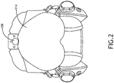
- the HMD 102 may include at least one eye tracking system 104, at least one head tracking system 106, at least one night vision sensor 108, at least one processor 110, at least one optical system 112, and at least one visor 114, some or all of which may be communicatively coupled at any given time.
- the HMD 102 may be implemented as any suitable HMD in any suitable environment.
- the HMD 102 may be implemented as a lightweight, wide field of view (FOV), off-the-visor HMD with an integrated night vision system that may provide a user with unparalleled and intuitive access to flight, navigation, tactical, and/or sensor information that may, for example, be displayed on the visor 114.
- FOV wide field of view
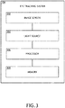
- the eye tracking system 104 may include at least one infrared light source 302 (e.g., at least one infrared light emitting diode (LED)), at least one infrared image sensor 304, at least one processor 306, and at least one memory 308, as well as other components, equipment, and/or devices commonly included in an eye tracking system, some or all of which may be communicatively coupled at any time, as shown in FIG. 3 .
- the eye tracking system 104 may be configured to track eye gestures, track movement of a user's eye, track a user's gaze, and/or otherwise receive inputs from a user's eyes.
- the eye tracking system 104 may be configured for performing fully automatic eye tracking operations of users in real time.
- the infrared light source 302 may be configured to emit infrared light onto an environment onto at least one eye of a user.
- the infrared sensitive image sensor 304 may be configured to capture images of the environment illuminated by the infrared light source 302.
- the processor 306 may be configured to process data received from the infrared sensitive image sensor 304 and output processed data to one or more devices or systems of the HMD 102 and/or the system 100. For example, the processor 306 may be configured to generate eye tracking data and output the generated eye tracking data to one of the devices (e.g., the processor 110) of the HMD 102 and/or the system 100.
- the processor 306 may be configured to run various software applications or computer code stored (e.g., maintained) in a non-transitory computer-readable medium (e.g., memory 308) and configured to execute various instructions or operations.
- the processor 306 may be implemented as a special purpose processor configured to execute instructions for performing (e.g., collectively performing if more than one processor) any or all of the operations disclosed throughout.
- the processor 306 may be configured to: receive image data from the infrared sensitive image sensor 304; track movement of at least one eye of a user based on the image data; and/or output eye tracking system data indicative of the tracked movement of the at least one eye of the user.
- the processor 306 may be configured to: perform visor distortion correction operations; perform eye mapping and alignment operations; output, via at least one data connection, eye tracking system data (e.g., indicative of eye azimuth and/or elevation) to an aircraft interface, simulator interface, and/or other computing device of the system; and/or perform a head tracking translation operation.
- eye tracking system data e.g., indicative of eye azimuth and/or elevation
- the head tracking system 106 may have optical, magnetic, and/or inertial tracking capability.
- the head tracking system 106 may include at least one sensor 402, at least one processor 404, and at least one memory 406, as well as other components, equipment, and/or devices commonly included in a head tracking system, some or all of which may be communicatively coupled at any time, as shown in FIG. 4 .
- the at least one sensor 402 may be at least one optical sensor (e.g., an optical infrared sensor configured to detect infrared light), at least one magnetic sensor, and/or at least one inertial sensor.
- the head tracking system 106 may be configured to determine and track a position and an orientation of a user's head relative to an environment.
- the head tracking system 106 may be configured for performing fully automatic head tracking operations in real time.
- the processor 404 of the head tracking system 106 may be configured to process data received from the sensors 402 and output processed data to one of the computing devices of the system and/or the processor 110 for use in generating images aligned with the user's field of view, such as augmented reality or virtual reality images aligned with the user's field of view to be displayed by the optical system 112 onto the visor 114.
- the processor 404 may be configured to determine and track a position and orientation of a user's head relative to an environment. Additionally, for example, the processor 404 may be configured to generate position and orientation data associated with such determined information and output the generated position and orientation data.
- the processor 404 may be configured to run various software applications or computer code stored in a non-transitory computer-readable medium (e.g., memory 406) and configured to execute various instructions or operations.
- the at least one processor 404 may be implemented as a special purpose processor configured to execute instructions for performing (e.g., collectively performing if more than one processor) any or all of the operations disclosed throughout.
- the night vision image sensor 108 may be configured to capture night vision images of the environment.
- the night vision image sensor 108 may be configured to detect infrared light.
- the night vision image sensor 108 may be configured to output night vision image data to the processor 110, which may output the images to the optical system 112 to be displayed onto the visor 114.
- the at least one processor 110 may be implemented as any suitable processor(s), such as at least one general purpose, at least one image processor, at least one graphics processing unit (GPU), and/or at least one special purpose processor, configured to execute instructions for performing (e.g., collectively performing if more than one processor) any or all of the operations disclosed throughout.
- the processor 110 may be communicatively coupled to the display element 116.
- the processor 110 may be configured to: receive the eye tracking system data; receive the head tracking system data; receive the night vision image data; generate and/or output synthetic vision system image data to the optical system 112, for example, based on the eye tracking system data and/or the head tracking system data; generate and/or output night vision image data to the optical system 112, for example, based on the eye tracking system data and/or the head tracking system data; generate and/or output augmented reality and/or virtual reality image data to the optical system, for example, based on the eye tracking system data and/or the head tracking system data; and/or generate and/or output other image data, which may include vehicle operation (e.g., flight) information, navigation information, tactical information, and/or sensor information to the optical system 112, for example, based on the eye tracking system data and/or the head tracking system data.
- vehicle operation e.g., flight
- the optical system 112 may be configured to receive image data from the processor 110 and project images onto the visor 114 for display to the user.
- the optical system 112 may include at least one display element 116. While the display element 116 is exemplarily depicted and described as being part of the optical system 112, in some embodiments, the display element 116 may be used in other display applications that do not include a optical system. In some embodiments, the optical system 112 may take the display element 116 as an input and transfer, translates, and/or form an image to the correct size and/or orientation for the user to view the information.
- the optical system 112 may include at least one lens, at least one mirror, diffraction gratings, at least one polarization sensitive component, at least one beam splitter, at least one combiner, at least one waveguide, at least one light pipe, at least one window, and/or the display element 116.
- the optical system 112 may include a collimator.
- the optical system 112 may include a relay lens.
- the optical system 112 may include a collimator and a combiner (e.g. a flat combiner).
- the optical system 112 may include a relay lens and a combiner (e.g., a curved combiner).
- the optical system 112 may include a prism collimator and a beam splitter.
- the optical system 112 may include collimator and a waveguide (e.g., a diffractive, mirror, or beam splitter based waveguide).
- the display element 116 may be an emissive display element, such as an OLED or micro-LED display element.
- the display element 116 may include red, green, blue, and white sub-pixels.
- the display element 116 may include red, green, and blue sub-pixels, such as in a RGBG sub-pixel architecture.
- the display element 116 may have an RGBW or an RGBGW sub-pixel architecture.
- the display element 116 may be configured to display RGB images and/or video, RGB+W images and/or video, RGB+G images and/or video, and/or grayscale (e.g., white grayscale or green grayscale) images and/or video.
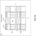
- the display element 116 may include a plurality of pixel groups 710.
- a pixel group is a group of sub-pixels.
- each of the plurality of pixel groups 710 may include a plurality (e.g., at least four) of sub-pixels 702, 704, 706, 708.
- a first sub-pixel 702 may be configured to output light of a first color
- a second sub-pixel 704 may be configured to output light of a second color
- a third sub-pixel 706 may be configured to output light of a third color
- a fourth sub-pixel 708 may be configured to output light.
- the fourth sub-pixel 708 may have a maximum brightness that is dimmer than a maximum brightness of each of the first sub-pixel 702, the second sub-pixel 704, and the third sub-pixel 706.
- the fourth sub-pixel 708 may have a maximum brightness that is at least four times dimmer than a maximum brightness of each of the first sub-pixel 702, the second sub-pixel 704, and the third sub-pixel 706.
- the fourth sub-pixel 708 may be a white sub-pixel configured to output white light.
- the fourth sub-pixel 708 may be a green sub-pixel configured to output green light.
- the fourth sub-pixel 708 may be any suitable color.
- the first sub-pixel 702 may be a red sub-pixel configured to output red light; however, in other embodiments, the first sub-pixel 702 may be any suitable color.
- the second sub-pixel 704 may be a green sub-pixel configured to output green light; however, in other embodiments, the second sub-pixel 704 may be any suitable color.
- the third sub-pixel 706 may be a blue sub-pixel configured to output blue light; however, in other embodiments, the third sub-pixel 706 may be any suitable color.
- the processor 110 may be further configured to: receive grayscale video, such as from the night vision sensor 108; and drive some or all of the fourth sub-pixels 708 corresponding to the grayscale (e.g., white grayscale or green grayscale) video such that grayscale images are displayed by the display element 116.
- grayscale video such as from the night vision sensor 108
- the processor 110 may be further configured to: receive grayscale video, such as from the night vision sensor 108; and drive some or all of the fourth sub-pixels 708 corresponding to the grayscale (e.g., white grayscale or green grayscale) video such that grayscale images are displayed by the display element 116.
- the grayscale e.g., white grayscale or green grayscale
- the processor 110 may be further configured to: receive red green blue (RGB) video; encode the RGB video as grayscale video; and drive some or all of the fourth sub-pixels 708 corresponding to the grayscale video such that grayscale images are displayed by the display element 116.
- RGB red green blue
- the processor 110 may be further configured to: receive red green blue (RGB) video; encode the RGB video as grayscale video; and drive some or all of the red, green, and blue pixels 702, 704, 706 corresponding to the RGB video and some or all of the fourth sub-pixels 708 corresponding to the grayscale video such that enhanced RGB plus grayscale images are displayed by the display element 116.
- RGB red green blue
- the processor 110 may be further configured to: operate in a day mode (e.g., for operating in a high luminance environment) and a night mode (e.g., for operating with night vision video in a low luminance environment).
- a day mode e.g., for operating in a high luminance environment
- a night mode e.g., for operating with night vision video in a low luminance environment
- the at least one processor 110 may be further configured to: receive red green blue (RGB) video, encode the RGB video as grayscale video, and drive some or all of the red, green, and blue pixels 702, 704, 706 corresponding to the RGB video and some or all of the fourth sub-pixels 708 corresponding to the grayscale video such that enhanced RGB plus grayscale images are displayed by the display element 116.
- RGB red green blue
- the at least one processor 110 may be further configured to: receive night vision grayscale video, and drive some or all of the fourth sub-pixels 708 corresponding to the night vision grayscale video such that night vision grayscale images are displayed by the display element 116.
- the system may be implemented as any suitable system, such as a vehicle (e.g., an aircraft (e.g., an airplane and/or helicopter), a watercraft, a submersible craft, an automobile, or a train), a wearable system, and/or a work station.
- a vehicle e.g., an aircraft (e.g., an airplane and/or helicopter), a watercraft, a submersible craft, an automobile, or a train), a wearable system, and/or a work station.
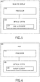
- the system may include at least one near-eye display 502.
- the near-eye display 502 may include some or all of the elements of the HMD 102 of FIG. 1 , and such elements may function similarly as described with respect to the HMD 102 of FIG. 1 .
- the system may be implemented as any suitable system, such as a vehicle (e.g., an aircraft (e.g., an airplane and/or helicopter), a watercraft, a submersible craft, an automobile, or a train), a wearable system, and/or a work station.
- a vehicle e.g., an aircraft (e.g., an airplane and/or helicopter), a watercraft, a submersible craft, an automobile, or a train), a wearable system, and/or a work station.
- the system may include at least one HUD 602.
- the HUD 602 may include some or all of the elements of the HMD 102 of FIG. 1 , and such elements may function similarly as described with respect to the HMD 102 of FIG. 1 .
- the display element 116 may have any suitable sub-pixel architecture.
- each pixel group 710 may include red, green, blue, and white sub-pixels 702, 704, 706, 708.
- such an architecture may allow for a small white sub-pixel 708.
- such an architecture may allow low luminance applications (e.g., night vision video applications) needing white to drive just the white sub-pixels 708, which may maximize image performance and MTF performance.
- such an architecture may allow for the red, green, blue, and white sub-pixels 702, 704, 706, 708 to all be driven to a same size line widths.
- such an architecture may allow for reduced video bandwidth for white only display.
- each pixel group 710 may include red, green, blue, and green sub-pixels with the second green sub-pixel dimmer than the other sub-pixels.
- each pixel group 710 may include red, green, blue, and white sub-pixels 702, 704, 706, 708.
- such an architecture may allow for a small white sub-pixel 708.
- such an architecture may allow low luminance applications (e.g., night vision video applications) needing white to drive just the white sub-pixels 708.
- such an architecture may allow for the red, green, blue, and white sub-pixels 702, 704, 706, 708 to all be driven to a same size line widths.
- such an architecture may allow for reduced video bandwidth for white only display.
- each pixel group 710 may include red, green, blue, and green sub-pixels with the second green sub-pixel dimmer than the other sub-pixels.
- the display element 116 may have a tiled five sub-pixel architecture.
- each pixel group 710 may include red, two green, blue, and white sub-pixels 702, 704, 706, 708.
- such an architecture may allow for a small white sub-pixel 708.
- such an architecture may allow low luminance applications (e.g., night vision video applications) needing white to drive just the white sub-pixels 708.
- such an architecture may allow for the red, green, blue, and white sub-pixels 702, 704, 706, 708 to all be driven to a same size line widths.
- such an architecture may allow for reduced video bandwidth for white only display.
- such an architecture may allow for a large monochrome subpixel for maximum pixel brightness for that color, while other color subpixel arrangement allows for those colors to be driven bright.
- such an architecture may provide best resolution for green as depicted, such that the central large pixel has the best resolution.
- the central large sub-pixel could be reduced in size and corner sub-pixels increased in size.
- the HMD 102 may include a reduced bandwidth RGB+W architecture.
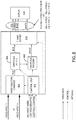
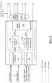
- FIGS. 8-9 exemplarily disclose an RGB+W architecture
- some embodiments may include any suitable RGB plus grayscale (e.g., white grayscale or green grayscale) architecture where the grayscale may be driven by dimmer sub-pixels (e.g., green or white dimmer sub-pixels).
- Such reduced bandwidth RGB+W architecture may include control logic 802, a video selector/combiner 804, a grayscale detector 806, a grayscale encoder 808, a memory (e.g., a frame buffer 810), and/or the display element 116, some or all of which may be communicatively coupled.
- each of the control logic 802, the video selector/combiner 804, the grayscale detector 806, and/or the grayscale encoder 808 may be implemented as a portion of the at least one processor 110, and/or the control logic 802, the video selector/combiner 804, the grayscale detector 806, and/or the grayscale encoder 808 may be implemented as separate processors of the at least one processor 110.
- the control logic 802 may be configured to control whether the system, the display element 116, and/or the at least one processor 110 operates in a day mode or night mode.
- the control logic 802 may be further configured to control a brightness of the display element 116, such as based on a detected luminance of the environment.
- the control logic 802 may be further configured to control other operations of the system, the display element 116, and/or the at least one processor 110.
- the control logic 802 may be further configured to output control settings to the video selector/combiner 804, the grayscale detector 806, and/or the grayscale encoder 808.
- the video selector/combiner 804 may be configured to receive one or more video inputs at any given time, such as an RGB video (e.g., synthetic vision system video), AR content video, and/or night vision video, and to receive control settings.
- the video selector/combiner 804 may be further configured to select one or more of the received video inputs such as based on a received control setting from the control logic 802, and if two or video inputs are selected, the video selector/combiner 804 may be further configured to combine the video inputs and output the combined video to the grayscale detector 806.
- the grayscale detector 806 may be configured to, based on control settings, detect grayscale video (e.g., night vision grayscale video used in night mode) and pass the video to the grayscale encoder. In some embodiments, the grayscale detector 806 may be further configured to re-encode RGB video to lower pixel resolution depending on a control setting. The grayscale detector 806 may output RGB video to the frame buffer 810, which may be passed to the display element 116. In some embodiments, the grayscale detector 806 may be configured to detect grayscale (e.g., based on control settings) or simply pass the RGB video to the frame buffer 810 without performing grayscale detection (e.g., based on control settings).
- grayscale video e.g., night vision grayscale video used in night mode
- the grayscale detector 806 may be further configured to re-encode RGB video to lower pixel resolution depending on a control setting.
- the grayscale detector 806 may output RGB video to the frame buffer 810, which may be passed to the display element 116.
- the grayscale encoder 808 may be configured to convert RGB video to grayscale video to be displayed by the white sub-pixels 708.
- the grayscale encoder 808 may output grayscale video to the frame buffer 810, which may be passed to the display element 116.
- the frame buffer 810 may receive RGB video and/or grayscale video. If both the RGB video and the grayscale video are received, the display element 116 may display enhanced RGB+W video. In some embodiments, based on a control setting, the frame buffer may only receive RGB video or grayscale video to be displayed by the display element 116.
- the architecture of FIG. 8 may be scaled to add or subtract a total number of sub-pixels as well as any combination of colors.
- the HMD 102 may include a scalable reduced bandwidth RGB+W architecture.
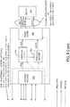
- Such architecture may include control logic 802, a video selector/combiner 804, a grayscale detector 806, a grayscale encoder 808, a memory (e.g., a frame buffer 810), receiver/decoder 902, a grayscale detector 904, a grayscale encoder 906, a memory (e.g., a frame buffer 902), and/or the display element 116, some or all of which may be communicatively coupled.
- each of the control logic 802, the video selector/combiner 804, the grayscale detector 806, the grayscale encoder 808, the receiver/decoder 902, the grayscale detector 904, and/or the grayscale encoder 906 may be implemented as a portion of the at least one processor 110, and/or the control logic 802, the video selector/combiner 804, the grayscale detector 806, the grayscale encoder 808, the receiver/decoder 902, the grayscale detector 904, and/or the grayscale encoder 906 may be implemented as separate processors of the at least one processor 110.
- the elements of FIG. 9 may be implemented similarly and function similarly to the elements of FIG. 8 , except that the scalable reduced bandwidth RGB+W architecture of FIG. 9 is scalable to allow for an optional intermediate video link.
- the optional intermediate video link may allow for scalability using the same architecture and may add optional control data within the video stream, which may be used to pass control data to a downstream video processor of the at least one processor 110.
- an exemplary embodiment of a method 1000 may include one or more of the following steps. Additionally, for example, some embodiments may include performing one more instances of the method 1000 iteratively, concurrently, and/or sequentially. Additionally, for example, at least some of the steps of the method 1000 may be performed in parallel and/or concurrently. Additionally, in some embodiments, at least some of the steps of the method 1000 may be performed non-sequentially.
- a step 1002 may include outputting, by a first sub-pixel of a pixel group of a display element, light of a first color.
- a step 1004 may include outputting, by a second sub-pixel of the pixel group of the display element, light of a second color.
- a step 1006 may include outputting, by a third sub-pixel of the pixel group of the display element, light of a third color.
- a step 1008 may include outputting, by a fourth sub-pixel of the pixel group of the display element, light, wherein the fourth sub-pixel is less bright than each of the first sub-pixel, the second sub-pixel, and the third sub-pixel.
- method 1000 may include any of the operations disclosed throughout.
- embodiments of the inventive concepts disclosed herein may be directed to a method and a system including a display element, wherein the display element includes a plurality of pixel groups such that each pixel group has a sub-pixel that is less efficient than other sub-pixels of the pixel group.
- At least one non-transitory computer-readable medium may refer to as at least one non-transitory computer-readable medium (e.g., e.g., at least one computer-readable medium implemented as hardware; e.g., at least one non-transitory processor-readable medium, at least one memory (e.g., at least one nonvolatile memory, at least one volatile memory, or a combination thereof; e.g., at least one random-access memory, at least one flash memory, at least one read-only memory (ROM) (e.g., at least one electrically erasable programmable read-only memory (EEPROM)), at least one on-processor memory (e.g., at least one on-processor cache, at least one on-processor buffer, at least one on-processor flash memory, at least one on-processor EEPROM, or a combination thereof), or a combination thereof), at least one storage device (e.g., at least one hard disk drive, or a digital versatile disk drive, or a magnetic tape
- At least one means one or a plurality of; for example, “at least one” may comprise one, two, three, ..., one hundred, or more.
- one or more means one or a plurality of; for example, “one or more” may comprise one, two, three, ..., one hundred, or more.
- zero or more means zero, one, or a plurality of; for example, “zero or more” may comprise zero, one, two, three, ..., one hundred, or more.
- the methods, operations, and/or functionality disclosed may be implemented as sets of instructions or software readable by a device. Further, it is understood that the specific order or hierarchy of steps in the methods, operations, and/or functionality disclosed are examples of exemplary approaches. Based upon design preferences, it is understood that the specific order or hierarchy of steps in the methods, operations, and/or functionality can be rearranged while remaining within the scope of the inventive concepts disclosed herein.
- the accompanying claims may present elements of the various steps in a sample order, and are not necessarily meant to be limited to the specific order or hierarchy presented.
- embodiments of the methods according to the inventive concepts disclosed herein may include one or more of the steps described herein. Further, such steps may be carried out in any desired order and two or more of the steps may be carried out simultaneously with one another. Two or more of the steps disclosed herein may be combined in a single step, and in some embodiments, one or more of the steps may be carried out as two or more sub-steps. Further, other steps or sub-steps may be carried in addition to, or as substitutes to one or more of the steps disclosed herein.
Landscapes
- Physics & Mathematics (AREA)
- Engineering & Computer Science (AREA)
- General Physics & Mathematics (AREA)
- Theoretical Computer Science (AREA)
- Optics & Photonics (AREA)
- Computer Hardware Design (AREA)
- General Engineering & Computer Science (AREA)
- Human Computer Interaction (AREA)
- Control Of Indicators Other Than Cathode Ray Tubes (AREA)
- Controls And Circuits For Display Device (AREA)
- Video Image Reproduction Devices For Color Tv Systems (AREA)
- Instrument Panels (AREA)
Applications Claiming Priority (1)
| Application Number | Priority Date | Filing Date | Title |
|---|---|---|---|
| US16/704,322 US11100892B2 (en) | 2019-12-05 | 2019-12-05 | Display element, system, and method |
Publications (3)
| Publication Number | Publication Date |
|---|---|
| EP3832632A2 true EP3832632A2 (fr) | 2021-06-09 |
| EP3832632A3 EP3832632A3 (fr) | 2021-08-04 |
| EP3832632B1 EP3832632B1 (fr) | 2025-01-29 |
Family
ID=73726726
Family Applications (1)
| Application Number | Title | Priority Date | Filing Date |
|---|---|---|---|
| EP20212006.9A Active EP3832632B1 (fr) | 2019-12-05 | 2020-12-04 | Afficheur avec vision nocturne |
Country Status (2)
| Country | Link |
|---|---|
| US (1) | US11100892B2 (fr) |
| EP (1) | EP3832632B1 (fr) |
Cited By (1)
| Publication number | Priority date | Publication date | Assignee | Title |
|---|---|---|---|---|
| EP4641553A4 (fr) * | 2023-01-26 | 2025-12-03 | Lg Electronics Inc | Dispositif d'affichage utilisant des éléments électroluminescents, et procédé d'excitation associé |
Families Citing this family (2)
| Publication number | Priority date | Publication date | Assignee | Title |
|---|---|---|---|---|
| CN119741898A (zh) * | 2023-09-26 | 2025-04-01 | 未来(北京)黑科技有限公司 | 一种抬头显示器、车辆及抬头显示器的控制方法 |
| IL315759A (en) * | 2024-09-12 | 2026-04-01 | Elbit Systems Ltd | Compatible monitor |
Family Cites Families (20)
| Publication number | Priority date | Publication date | Assignee | Title |
|---|---|---|---|---|
| US7012588B2 (en) * | 2001-06-05 | 2006-03-14 | Eastman Kodak Company | Method for saving power in an organic electroluminescent display using white light emitting elements |
| EP1770676B1 (fr) | 2005-09-30 | 2017-05-03 | Semiconductor Energy Laboratory Co., Ltd. | Dispositif d'affichage et dispositif électronique |
| JP2011064959A (ja) | 2009-09-17 | 2011-03-31 | Global Oled Technology Llc | 表示装置 |
| KR101588336B1 (ko) | 2009-12-17 | 2016-01-26 | 삼성디스플레이 주식회사 | 데이터 처리 방법 및 이를 수행하기 위한 표시 장치 |
| US20120299947A1 (en) | 2010-01-22 | 2012-11-29 | Sharp Kabushiki Kaisha | Display device |
| WO2012053404A1 (fr) | 2010-10-19 | 2012-04-26 | シャープ株式会社 | Afficheur |
| US9633607B1 (en) | 2013-12-02 | 2017-04-25 | Amazon Technologies, Inc. | Adaptive RGBW conversion |
| CN103762224B (zh) | 2014-01-29 | 2017-01-04 | 京东方科技集团股份有限公司 | 有机电致发光显示面板 |
| CN104036700B (zh) | 2014-05-30 | 2016-02-03 | 京东方科技集团股份有限公司 | 显示面板、显示方法和显示装置 |
| US10885827B2 (en) | 2014-12-29 | 2021-01-05 | Novatek Microelectronics Corp. | Display panel for effectively dispersing specific sub-pixels |
| US11461936B2 (en) * | 2015-03-17 | 2022-10-04 | Raytrx, Llc | Wearable image manipulation and control system with micro-displays and augmentation of vision and sensing in augmented reality glasses |
| KR102456353B1 (ko) * | 2015-04-29 | 2022-10-20 | 엘지디스플레이 주식회사 | 4원색 유기발광 표시장치와 그 구동방법 |
| JP6499511B2 (ja) | 2015-05-19 | 2019-04-10 | 株式会社ジャパンディスプレイ | 表示装置 |
| CN106023819B (zh) | 2016-05-27 | 2019-08-30 | 京东方科技集团股份有限公司 | 像素结构、阵列基板、显示装置和显示装置的驱动方法 |
| KR102589145B1 (ko) | 2016-10-04 | 2023-10-12 | 엘지전자 주식회사 | 영상표시장치 |
| US20180137602A1 (en) | 2016-11-14 | 2018-05-17 | Google Inc. | Low resolution rgb rendering for efficient transmission |
| JP2019174537A (ja) | 2018-03-27 | 2019-10-10 | 株式会社ジャパンディスプレイ | 表示装置 |
| CN108810507B (zh) * | 2018-06-15 | 2019-10-29 | 京东方科技集团股份有限公司 | 一种色域转换方法及色域转换器、显示装置 |
| FR3087582B1 (fr) * | 2018-10-22 | 2021-09-03 | Microoled | Dispositif d'affichage jour et nuit |
| US11367377B2 (en) * | 2019-08-02 | 2022-06-21 | Tianma Japan, Ltd. | Display device |
-
2019
- 2019-12-05 US US16/704,322 patent/US11100892B2/en active Active
-
2020
- 2020-12-04 EP EP20212006.9A patent/EP3832632B1/fr active Active
Cited By (1)
| Publication number | Priority date | Publication date | Assignee | Title |
|---|---|---|---|---|
| EP4641553A4 (fr) * | 2023-01-26 | 2025-12-03 | Lg Electronics Inc | Dispositif d'affichage utilisant des éléments électroluminescents, et procédé d'excitation associé |
Also Published As
| Publication number | Publication date |
|---|---|
| EP3832632B1 (fr) | 2025-01-29 |
| US11100892B2 (en) | 2021-08-24 |
| US20210174764A1 (en) | 2021-06-10 |
| EP3832632A3 (fr) | 2021-08-04 |
Similar Documents
| Publication | Publication Date | Title |
|---|---|---|
| EP3832632B1 (fr) | Afficheur avec vision nocturne | |
| US10401627B1 (en) | Stacked display panels for image enhancement | |
| US8681073B1 (en) | System for and method of controlling contrast or color contrast in see-through displays | |
| US9378691B2 (en) | Display device and method for driving display device | |
| US10719127B1 (en) | Extended life display by utilizing eye tracking | |
| US20130328948A1 (en) | Combined Emissive and Reflective Dual Modulation Display System | |
| US10957247B1 (en) | Display with sub-pixel drive | |
| KR20170067856A (ko) | 두부 장착형 표시 장치, 두부 장착형 표시 장치의 제어 방법 및 컴퓨터 프로그램을 갖는 컴퓨터 판독 가능 기록 매체 | |
| US11127371B2 (en) | Extending brightness dimming range of displays via image frame manipulation | |
| US11778148B2 (en) | Variable-pitch color emitting display | |
| CN110036436A (zh) | 光源控制装置、显示装置、图像处理装置、光源控制装置的控制方法以及控制程序 | |
| US10699673B2 (en) | Apparatus, systems, and methods for local dimming in brightness-controlled environments | |
| US20170116950A1 (en) | Liquid crystal display with variable drive voltage | |
| US20170278443A1 (en) | Display device and control method thereof, and display system | |
| US8547295B2 (en) | Motion simulator and display system typically using light-emitting diodes | |
| KR102639962B1 (ko) | 디스플레이와 관련된 개선사항들 | |
| US11137605B1 (en) | Near-eye display assembly with enhanced display resolution | |
| JP2015154420A (ja) | 表示装置 | |
| US11302289B2 (en) | Display element, system, and method | |
| US11568813B1 (en) | Pixel level burn-in compensation for light-emitting diode based displays | |
| US12474578B1 (en) | Narrowband reflective optical combiner with narrowband display device having multi-coloured backlight unit | |
| Ali et al. | Night vision goggle stimulation using LCoS and DLP projection technology, which is better? | |
| JP2014132332A (ja) | 視覚的快適性が改善されたヘッドアップディスプレイ | |
| Ross et al. | AMOLED image source for use in integrated panoramic night vision goggle (IPNVG) | |
| Haas et al. | Session 2. MicroLED and VR/ARs |
Legal Events
| Date | Code | Title | Description |
|---|---|---|---|
| PUAI | Public reference made under article 153(3) epc to a published international application that has entered the european phase |
Free format text: ORIGINAL CODE: 0009012 |
|
| STAA | Information on the status of an ep patent application or granted ep patent |
Free format text: STATUS: THE APPLICATION HAS BEEN PUBLISHED |
|
| AK | Designated contracting states |
Kind code of ref document: A2 Designated state(s): AL AT BE BG CH CY CZ DE DK EE ES FI FR GB GR HR HU IE IS IT LI LT LU LV MC MK MT NL NO PL PT RO RS SE SI SK SM TR |
|
| PUAL | Search report despatched |
Free format text: ORIGINAL CODE: 0009013 |
|
| AK | Designated contracting states |
Kind code of ref document: A3 Designated state(s): AL AT BE BG CH CY CZ DE DK EE ES FI FR GB GR HR HU IE IS IT LI LT LU LV MC MK MT NL NO PL PT RO RS SE SI SK SM TR |
|
| RIC1 | Information provided on ipc code assigned before grant |
Ipc: G09G 3/32 20160101AFI20210629BHEP Ipc: G09G 3/20 20060101ALI20210629BHEP Ipc: G09G 5/02 20060101ALI20210629BHEP Ipc: G02B 27/01 20060101ALI20210629BHEP |
|
| STAA | Information on the status of an ep patent application or granted ep patent |
Free format text: STATUS: REQUEST FOR EXAMINATION WAS MADE |
|
| 17P | Request for examination filed |
Effective date: 20220204 |
|
| RBV | Designated contracting states (corrected) |
Designated state(s): AL AT BE BG CH CY CZ DE DK EE ES FI FR GB GR HR HU IE IS IT LI LT LU LV MC MK MT NL NO PL PT RO RS SE SI SK SM TR |
|
| STAA | Information on the status of an ep patent application or granted ep patent |
Free format text: STATUS: EXAMINATION IS IN PROGRESS |
|
| 17Q | First examination report despatched |
Effective date: 20230322 |
|
| GRAP | Despatch of communication of intention to grant a patent |
Free format text: ORIGINAL CODE: EPIDOSNIGR1 |
|
| STAA | Information on the status of an ep patent application or granted ep patent |
Free format text: STATUS: GRANT OF PATENT IS INTENDED |
|
| RIC1 | Information provided on ipc code assigned before grant |
Ipc: G02B 27/01 20060101ALI20240628BHEP Ipc: G09G 3/32 20160101AFI20240628BHEP |
|
| INTG | Intention to grant announced |
Effective date: 20240718 |
|
| GRAS | Grant fee paid |
Free format text: ORIGINAL CODE: EPIDOSNIGR3 |
|
| GRAA | (expected) grant |
Free format text: ORIGINAL CODE: 0009210 |
|
| STAA | Information on the status of an ep patent application or granted ep patent |
Free format text: STATUS: THE PATENT HAS BEEN GRANTED |
|
| AK | Designated contracting states |
Kind code of ref document: B1 Designated state(s): AL AT BE BG CH CY CZ DE DK EE ES FI FR GB GR HR HU IE IS IT LI LT LU LV MC MK MT NL NO PL PT RO RS SE SI SK SM TR |
|
| REG | Reference to a national code |
Ref country code: GB Ref legal event code: FG4D |
|
| REG | Reference to a national code |
Ref country code: CH Ref legal event code: EP |
|
| REG | Reference to a national code |
Ref country code: DE Ref legal event code: R096 Ref document number: 602020045452 Country of ref document: DE |
|
| REG | Reference to a national code |
Ref country code: IE Ref legal event code: FG4D |
|
| REG | Reference to a national code |
Ref country code: NL Ref legal event code: MP Effective date: 20250129 |
|
| PG25 | Lapsed in a contracting state [announced via postgrant information from national office to epo] |
Ref country code: NL Free format text: LAPSE BECAUSE OF FAILURE TO SUBMIT A TRANSLATION OF THE DESCRIPTION OR TO PAY THE FEE WITHIN THE PRESCRIBED TIME-LIMIT Effective date: 20250129 |
|
| PG25 | Lapsed in a contracting state [announced via postgrant information from national office to epo] |
Ref country code: RS Free format text: LAPSE BECAUSE OF FAILURE TO SUBMIT A TRANSLATION OF THE DESCRIPTION OR TO PAY THE FEE WITHIN THE PRESCRIBED TIME-LIMIT Effective date: 20250429 |
|
| PG25 | Lapsed in a contracting state [announced via postgrant information from national office to epo] |
Ref country code: FI Free format text: LAPSE BECAUSE OF FAILURE TO SUBMIT A TRANSLATION OF THE DESCRIPTION OR TO PAY THE FEE WITHIN THE PRESCRIBED TIME-LIMIT Effective date: 20250129 |
|
| PG25 | Lapsed in a contracting state [announced via postgrant information from national office to epo] |
Ref country code: PL Free format text: LAPSE BECAUSE OF FAILURE TO SUBMIT A TRANSLATION OF THE DESCRIPTION OR TO PAY THE FEE WITHIN THE PRESCRIBED TIME-LIMIT Effective date: 20250129 |
|
| PG25 | Lapsed in a contracting state [announced via postgrant information from national office to epo] |
Ref country code: ES Free format text: LAPSE BECAUSE OF FAILURE TO SUBMIT A TRANSLATION OF THE DESCRIPTION OR TO PAY THE FEE WITHIN THE PRESCRIBED TIME-LIMIT Effective date: 20250129 |
|
| REG | Reference to a national code |
Ref country code: LT Ref legal event code: MG9D |
|
| PG25 | Lapsed in a contracting state [announced via postgrant information from national office to epo] |
Ref country code: NO Free format text: LAPSE BECAUSE OF FAILURE TO SUBMIT A TRANSLATION OF THE DESCRIPTION OR TO PAY THE FEE WITHIN THE PRESCRIBED TIME-LIMIT Effective date: 20250429 Ref country code: IS Free format text: LAPSE BECAUSE OF FAILURE TO SUBMIT A TRANSLATION OF THE DESCRIPTION OR TO PAY THE FEE WITHIN THE PRESCRIBED TIME-LIMIT Effective date: 20250529 |
|
| REG | Reference to a national code |
Ref country code: AT Ref legal event code: MK05 Ref document number: 1764265 Country of ref document: AT Kind code of ref document: T Effective date: 20250129 |
|
| PG25 | Lapsed in a contracting state [announced via postgrant information from national office to epo] |
Ref country code: HR Free format text: LAPSE BECAUSE OF FAILURE TO SUBMIT A TRANSLATION OF THE DESCRIPTION OR TO PAY THE FEE WITHIN THE PRESCRIBED TIME-LIMIT Effective date: 20250129 |
|
| PG25 | Lapsed in a contracting state [announced via postgrant information from national office to epo] |
Ref country code: PT Free format text: LAPSE BECAUSE OF FAILURE TO SUBMIT A TRANSLATION OF THE DESCRIPTION OR TO PAY THE FEE WITHIN THE PRESCRIBED TIME-LIMIT Effective date: 20250529 Ref country code: LV Free format text: LAPSE BECAUSE OF FAILURE TO SUBMIT A TRANSLATION OF THE DESCRIPTION OR TO PAY THE FEE WITHIN THE PRESCRIBED TIME-LIMIT Effective date: 20250129 |
|
| PG25 | Lapsed in a contracting state [announced via postgrant information from national office to epo] |
Ref country code: GR Free format text: LAPSE BECAUSE OF FAILURE TO SUBMIT A TRANSLATION OF THE DESCRIPTION OR TO PAY THE FEE WITHIN THE PRESCRIBED TIME-LIMIT Effective date: 20250430 Ref country code: BG Free format text: LAPSE BECAUSE OF FAILURE TO SUBMIT A TRANSLATION OF THE DESCRIPTION OR TO PAY THE FEE WITHIN THE PRESCRIBED TIME-LIMIT Effective date: 20250129 |
|
| PG25 | Lapsed in a contracting state [announced via postgrant information from national office to epo] |
Ref country code: AT Free format text: LAPSE BECAUSE OF FAILURE TO SUBMIT A TRANSLATION OF THE DESCRIPTION OR TO PAY THE FEE WITHIN THE PRESCRIBED TIME-LIMIT Effective date: 20250129 |
|
| PG25 | Lapsed in a contracting state [announced via postgrant information from national office to epo] |
Ref country code: SE Free format text: LAPSE BECAUSE OF FAILURE TO SUBMIT A TRANSLATION OF THE DESCRIPTION OR TO PAY THE FEE WITHIN THE PRESCRIBED TIME-LIMIT Effective date: 20250129 |
|
| PG25 | Lapsed in a contracting state [announced via postgrant information from national office to epo] |
Ref country code: SM Free format text: LAPSE BECAUSE OF FAILURE TO SUBMIT A TRANSLATION OF THE DESCRIPTION OR TO PAY THE FEE WITHIN THE PRESCRIBED TIME-LIMIT Effective date: 20250129 |
|
| PG25 | Lapsed in a contracting state [announced via postgrant information from national office to epo] |
Ref country code: DK Free format text: LAPSE BECAUSE OF FAILURE TO SUBMIT A TRANSLATION OF THE DESCRIPTION OR TO PAY THE FEE WITHIN THE PRESCRIBED TIME-LIMIT Effective date: 20250129 |
|
| PG25 | Lapsed in a contracting state [announced via postgrant information from national office to epo] |
Ref country code: IT Free format text: LAPSE BECAUSE OF FAILURE TO SUBMIT A TRANSLATION OF THE DESCRIPTION OR TO PAY THE FEE WITHIN THE PRESCRIBED TIME-LIMIT Effective date: 20250129 |
|
| PG25 | Lapsed in a contracting state [announced via postgrant information from national office to epo] |
Ref country code: CZ Free format text: LAPSE BECAUSE OF FAILURE TO SUBMIT A TRANSLATION OF THE DESCRIPTION OR TO PAY THE FEE WITHIN THE PRESCRIBED TIME-LIMIT Effective date: 20250129 Ref country code: EE Free format text: LAPSE BECAUSE OF FAILURE TO SUBMIT A TRANSLATION OF THE DESCRIPTION OR TO PAY THE FEE WITHIN THE PRESCRIBED TIME-LIMIT Effective date: 20250129 |
|
| PG25 | Lapsed in a contracting state [announced via postgrant information from national office to epo] |
Ref country code: RO Free format text: LAPSE BECAUSE OF FAILURE TO SUBMIT A TRANSLATION OF THE DESCRIPTION OR TO PAY THE FEE WITHIN THE PRESCRIBED TIME-LIMIT Effective date: 20250129 |
|
| PG25 | Lapsed in a contracting state [announced via postgrant information from national office to epo] |
Ref country code: SK Free format text: LAPSE BECAUSE OF FAILURE TO SUBMIT A TRANSLATION OF THE DESCRIPTION OR TO PAY THE FEE WITHIN THE PRESCRIBED TIME-LIMIT Effective date: 20250129 |
|
| REG | Reference to a national code |
Ref country code: DE Ref legal event code: R097 Ref document number: 602020045452 Country of ref document: DE |
|
| PLBE | No opposition filed within time limit |
Free format text: ORIGINAL CODE: 0009261 |
|
| STAA | Information on the status of an ep patent application or granted ep patent |
Free format text: STATUS: NO OPPOSITION FILED WITHIN TIME LIMIT |
|
| 26N | No opposition filed |
Effective date: 20251030 |
|
| PGFP | Annual fee paid to national office [announced via postgrant information from national office to epo] |
Ref country code: DE Payment date: 20251126 Year of fee payment: 6 |
|
| PGFP | Annual fee paid to national office [announced via postgrant information from national office to epo] |
Ref country code: GB Payment date: 20251120 Year of fee payment: 6 |
|
| PGFP | Annual fee paid to national office [announced via postgrant information from national office to epo] |
Ref country code: FR Payment date: 20251119 Year of fee payment: 6 |