EP3832818B1 - Appareillage de commutation - Google Patents
Appareillage de commutation Download PDFInfo
- Publication number
- EP3832818B1 EP3832818B1 EP19844890.4A EP19844890A EP3832818B1 EP 3832818 B1 EP3832818 B1 EP 3832818B1 EP 19844890 A EP19844890 A EP 19844890A EP 3832818 B1 EP3832818 B1 EP 3832818B1
- Authority
- EP
- European Patent Office
- Prior art keywords
- door
- housing
- switchgear
- bolt
- sealing material
- Prior art date
- Legal status (The legal status is an assumption and is not a legal conclusion. Google has not performed a legal analysis and makes no representation as to the accuracy of the status listed.)
- Active
Links
Images







Classifications
-
- H—ELECTRICITY
- H02—GENERATION; CONVERSION OR DISTRIBUTION OF ELECTRIC POWER
- H02B—BOARDS, SUBSTATIONS OR SWITCHING ARRANGEMENTS FOR THE SUPPLY OR DISTRIBUTION OF ELECTRIC POWER
- H02B1/00—Frameworks, boards, panels, desks, casings; Details of substations or switching arrangements
- H02B1/26—Casings; Parts thereof or accessories therefor
- H02B1/28—Casings; Parts thereof or accessories therefor dustproof, splashproof, drip-proof, waterproof or flameproof
-
- H—ELECTRICITY
- H02—GENERATION; CONVERSION OR DISTRIBUTION OF ELECTRIC POWER
- H02B—BOARDS, SUBSTATIONS OR SWITCHING ARRANGEMENTS FOR THE SUPPLY OR DISTRIBUTION OF ELECTRIC POWER
- H02B1/00—Frameworks, boards, panels, desks, casings; Details of substations or switching arrangements
- H02B1/26—Casings; Parts thereof or accessories therefor
- H02B1/30—Cabinet-type casings; Parts thereof or accessories therefor
- H02B1/38—Hinged covers or doors
Definitions
- the present invention relates to a switchgear, and more particularly, to a metal-enclosed switchgear which requires pressure-resistant performance.
- a metal-enclosed switchgear in which high-voltage equipment such as a switch is accommodated in a metal closed box, is widely used in facilities with large electric equipment capacity such as a power station, a substation, an iron mill, and a petrochemical plant.
- the metal-enclosed switchgears are roughly classified into three types of switchgears: a metal clad type switchgear in which the inner space is separated into multiple compartments (storage space) with a metal partition board; a compartment type switchgear in which the inner space is separated into multiple compartments with a non-metal (insulating) partition board; and a cubicle type switchgear other than those switchgears.
- Patent Literature 1 For example, with regard to an object to increase sealability of the housing, a technique as in Patent Literature 1 is known.
- Patent Literature 1 discloses an "electronic control device in which a connector-mounted circuit board is stored in the inner space of a housing, and the inner space is made waterproof space with a sealing material". Furthermore, PTL 2 discloses a casing for a power conversion device including a box-shaped casing body portion having an opening portion on the front surface side. PTL 3 discloses a switchgear, wherein a closing edge having an initial section, an intermediate section and an end section is substantially Z-shaped, wherein a magnetically conductive HF sealing element is applied to the inside of the door in the region of the end section of the closing edge.
- PTL 4 discloses a metal-enclosed switchgear, wherein a flange of a front panel is formed by a compressed groove on which a seal is applied, wherein said groove is connected to the panel, and wherein a recessed surface is provided with openings arranged uniformly in series for the attachment of supports or accessories.
- PTL 5 discloses another switch gear, wherein edges of the door for engaging with a sealing strip have an inwardly angled sealing edge at an angle of about 45°.
- PTL 6 also discloses a switch gear having a box-like cabinet body, wherein an edge of a door is set back so far against the cabinet body that a door frame forms an accessible receptacle which is open at the front so that a cover strip is inserted into the slot-like receptacle.
- PTL 7 discloses a rectangular receptacle comprising clamp bolts extending through a yoke and a notch in a flange of a cover, wherein each bolt having its head positioned between side arms of the yoke and a nut screwed on to the upper end of each bolt for drawing said flanges and said yokes together and forcing the gasket to be impressed upon the edges of the body.
- PTL 8 discloses an enclosure, which is externally hinged and has a positive internal locking mechanism/arrangement to ensure uniform sealing all around, between body and cover.
- PTL 9 discloses yet another casing, wherein a door or an extension has on the inside on its frame a profile forming a concave groove, wherein said groove is adapted to receive and to hold a seal.
- PTL 10 also discloses a cabinet for electrical equipment.
- PTL 11 describes an improved structure for an electrical equipment storage box designed to prevent water accumulation and ensure dust and water resistance.
- the box features a main body with an opening and a door equipped with inner and outer gaskets. These gaskets, along with a rib on the door and a partition wall, enhance sealing performance and prevent water ingress.
- the design includes sloped surfaces to direct water away and a protective overhang to shield against rain and UV light, making it suitable for outdoor use.
- a device structure to prevent the influence on the outside due to the high-temperature and high-pressure gas (hot gas) upon occurrence of a short circuit accident (arc accident) is considered.
- prevention of the discharge of the high-temperature and high-pressure gas (hot gas) from the gap between the housing and the door of the switchgear is a significant object to protect the peripheral equipment and ensure safety for the worker.
- Patent Literature 1 is for a comparatively small electronic control device.
- the structure of the sealing material and the groove described in Patent Literature 1 is to be applied to the door of the switchgear, as the contact area between the members such as the housing and the door and the sealing member is increased, a large force is required when closing the door.
- the switchgear accommodates high-voltage equipment such as a switch inside, and periodical maintenance and inspection are required. Accordingly, an easily-openable/closable door structure is desired.
- the purpose of the present invention is to provide a door seal structure (packing structure), with high sealing performance, which enables opening/closing of the door with ease, in a metal-enclosed switchgear.
- the present invention in the metal-enclosed switchgear, it is possible to realize a door seal structure (packing structure), with high sealing performance, which enables closing of the door with ease.
- Figure 1 is a perspective view showing an appearance of a housing of the switchgear according to the present example.
- Figure 2 shows a state where a door 1 of the switchgear is open.
- Figure 3 to Figure 6 are enlarged views showing a cross section of a part A in Figure 1 .
- Figure 3 shows a state where the door 1 is open (strictly, a state immediately before closing of the door 1).
- Figure 4 shows a state where the door 1 is closed.
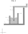
- Figure 5 and Figure 6 are modifications of Figure 4 respectively.
- the present invention is also applicable to a metal clad type switchgear in which the inner space of the housing 4 is separated into multiple compartments (storage space) with a metal partition board, a compartment type switchgear in which the inner space is separated into multiple compartments with a non-metal (insulating) partition board, or a cubicle type switchgear other than those switchgears.
- X, Y, and Z axes are shown to clarify the arrangement (relationship) of the configuration in the respective drawings.
- the axes respectively correspond to the width direction (X axis), the depth direction (Y axis), and the height direction (Z axis) of the switchgear.
- the switchgear according to the present example is a metal closed box, i.e., a so-called metal-enclosed switchgear, in which the door 1 having a handle 22 is installed openably/closably with respect to the housing 4.
- steel material such as iron or stainless steel (SUS material) is mainly used as the door 1 and the housing 4.
- SUS material stainless steel
- the handle 22 is connected to a bolt structure (door lock mechanism) as described later.
- the handle 22 is a handle upon opening/closing of the door 1, and upon closing the door 1, becomes a part of the door lock mechanism to fix the door 1 to the housing 4.
- the door 1 is installed, openably/closably (rotatably) with respect to the housing 4, with unshown multiple hinge joints (hinges). Note that to secure equipment installation space in the switchgear, it is desirable that the door 1 is an outward-opening door as shown in Figure 2 .
- a plate 2 to limit misalignment of a sealing material is provided inside of the door 1.
- a plate 5 having a wedge-shaped cross section is provided on the door side (a joint part with respect to the door 1 when the door is closed) of the housing 4.
- the wedge-shaped plate 5 is shown as a frame-shaped member provided around the opening (the joint part with respect to the door 1 when the door is closed) of the housing 4 to surround the opening and to be projected from the housing 4.
- the wedge-shaped plate 5 may be configured with four plate-shaped members, respectively extended in a horizontal direction (x direction) or a vertical direction (z direction) with respect to an installation surface (floor surface) of the housing 4 in one side of the opening of the housing 4, and projected from the housing 4.
- the wedge-shaped plate 5 has a wedge-shaped cross-sectional shape so as to press the sealing material with a comparatively small force when closing the door 1, and furthermore, so as to secure sealability of the switchgear.
- the cross-sectional shape is not necessarily limited to the wedge shape. That is, it is possible to paraphrase the wedge-shaped plate 5 into a sealing material pressing member, a frame-shaped member to press the sealing material, a plate-shaped member to press the sealing material, or the like.
- Figure 3 is an enlarged view of the seal structure (packing structure) in a state where the door 1 is open (strictly, a state immediately before closing of the door 1).
- Figure 4 is an enlarged view of the seal structure (packing structure) in a state where the door 1 is closed.
- two plates 2a and 2b to limit misalignment of the sealing material 3 are provided inside of the door 1 of the switchgear.
- the two plates 2a and 2b form a groove between them.
- the two plates 2a and 2b are two plate-shaped members vertically fixed with respect to the door 1 in one side of the door 1.
- the sealing material 3 is fitted and fixed in the groove between the two plates 2a and 2b. That is, the two plates 2a and 2b are support members to support-fix the sealing material 3 on the door 1.
- the plate 5 with a wedge-shaped cross-sectional end is provided on the door side (the joint part with respect to the door 1 when the door is closed) of the housing 4 of the switchgear.
- the wedge-shaped plate 5 is pressed against the sealing material 3 and caused to bite into the sealing material 3. That is, the wedge-shaped plate 5 is a pressing member to press the sealing material 3.
- the movement of the sealing material 3 is limited with the two plates 2a and 2b. For example, even when a high pressure to cause heated and expanded high-temperature and high-pressure gas (hot gas) inside of the switchgear has acted, it is possible to maintain the sealing without misalignment of the sealing material 3.
- hot gas heated and expanded high-temperature and high-pressure gas
- the plate 5, provided on the housing 4 side By forming the plate 5, provided on the housing 4 side, in a wedge shape, the area in contact with the sealing material 3 is small, and a high surface pressure acts on the sealing material 3. It is possible, even with a small force, to effectively prevent leakage of high pressure (high-pressure gas) occurred inside of the switchgear to the outside.
- the depth of the groove formed with the two plates 2a and 2b (the depth in the y direction between 2a and 2b in Figure 4 ) to be longer than the width of the groove formed with the two plates 2a and 2b (the width in the x direction between 2a, 2b in Figure 4 )
- the high-temperature and high-pressure gas (hot gas) which occurs in the switchgear hardly enters in the groove, and it is possible to reduce the possibility of the contact between the high-temperature and high-pressure gas (hot gas) and the sealing material 3.
- an elastic material for example, an organic material such as natural rubber, synthetic rubber such as nitrile rubber, silicone rubber, acrylic rubber, styrene-butadiene rubber, fluorine rubber, ethylenepropylene rubber, or tetrafluoroethylene rubber resin, can be given.
- an organic material such as natural rubber, synthetic rubber such as nitrile rubber, silicone rubber, acrylic rubber, styrene-butadiene rubber, fluorine rubber, ethylenepropylene rubber, or tetrafluoroethylene rubber resin.
- hot gas high-temperature and high-pressure gas
- a non-organic material having elasticity to secure a fixed amount of biting of the wedge-shaped plate 5 into the sealing material 3 may be used as long as it prevents leakage of the high-temperature and high-pressure gas (hot gas) to the outside.
- the wedge-shaped plate 5 having a shape to cover (surround) the entire circumference of the door opening is shown. It may be configured such that the wedge-shaped plate 5 is e.g. a wedge-shaped member, and multiple wedge-shaped members are scattered, in a dotted line, so as to surround the door opening.
- the shape viewed from the front side of the switchgear may be line shape or dotted line shape as long as it is a shape to bite into the material 3 in the respective cross sections as shown in Figure 3 to Figure 5 .
- the packing (sealing material 3) into the outer periphery of the door 1, and cause the edge of the housing 4 (wedge-shaped plate 5) to bite into the packing (sealing material 3), the leakage of gas or the like occurred in the housing 4 is prevented.
- the door 1 is somewhat misaligned upon increase of the inner pressure of the housing 4; however, since the amount of biting of the edge of the housing 4 (wedge-shaped plate 5) into the packing (sealing material 3) is larger than the amount of misalignment, no gap occurs between the door 1 and the housing 4, and the leakage of gas or the like does not occur. Further, the misalignment of the packing (sealing material 3) due to pressure is prevented by holding the packing (sealing material 3) between the two plates 2a and 2b.
- the housing 4 by forming the housing 4 to have a wedge-shaped (sharp) edge to reduce the contact area with respect to the packing (sealing material 3), the structure to increase the surface pressure for sufficient biting with a small force is given. With this configuration, upon closing of the door 1, a large force is not required, and it is possible to easily and reliably prevent the leakage of gas or the like occurred inside of the housing 4.
- Figure 5 and Figure 6 are modifications of the seal structure (packing structure) in Figure 4 .
- the plate 2a on the hinge joint (hinge) side is shorter than the plate 2b, as in the case of a plate 2c in Figure 5 , it is possible to avoid the possibility of contact (interference) between the plate 2a (2c) and wedge-shaped plate 5 upon opening/closing of the door 1.
- a plate to limit the misalignment of a sealing material, the sealing material, and a wedge-shaped plate are provided on both door 1 side and housing 4 side, as a double seal structure (packing structure).
- one plate 2a and a plate 5a with a wedge-shaped end are provided on the door 1, and a sealing material 3a is fitted and fixed in the groove formed between these plates.
- a similar structure one plate 2b, a plate 5b with a wedge-shaped end, and a sealing material 3b is provided on the housing 4 oppositely, and the respective wedge-shaped plates 5a and 5b are pressed against the sealing materials 3a and 3b, to seal the switchgear.
- the number of the sealing materials (3a and 3b) is large, it is possible to further improve the pressure resistance.
- FIG. 7 shows the bolt structure (door lock mechanism) of the switchgear according to the present example viewed from the inside of the door 1.
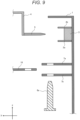
- Figure 8 shows a state where the door 1 is locked (fixed) to the housing with the bolt structure (door lock mechanism).
- Figure 9 and Figure 10 are enlarged views respectively showing the details of the B-B cross section in Figure 7 and Figure 8 .
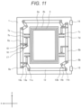
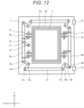
- Figure 11 and Figure 12 are modifications of Figure 7 and Figure 8 respectively.
- the bolt structure (door lock mechanism) as shown in Figure 7 is provided inside of the door 1 of the switchgear.
- the bolt structure (door lock mechanism) is provided inside of the door 1 (the housing 4 side) and further inside (the center side of the door 1) than the seal structure (the plates 2a and 2b and the sealing material 3) described in Example 1.
- the bolt structure (door lock mechanism) is configured with two bolts 6a and 6b provided on both sides of the door 1, L-shaped metal fittings 9 and 14 respectively connected to the bolts 6a and 6b with pins 8a and 8b, a rod 12 connected to the L-shaped metal fittings 9 and 14 with pins 11a and 11b, and perforated plates 7a to 7d which are provided on the door 1 side and through which the bolts are inserted.
- the L-shaped metal fitting 9 is connected via a handle shaft 10 to the handle 22 provided on the opposite side of the door 1. It is possible to operate the bolt structure (door lock mechanism) by operating the handle 22 to move the bolts 6a and 6b in the vertical direction in the drawing.
- the L-shaped metal fitting 14 is rotatably attached to the door 1 with a shaft 13, and is rotated about the shaft 13 as a rotation center in accordance with movement of the L-shaped metal fitting 9 and the rod 12 with the handle 22.
- the door 1 is connected to the unshown housing 4 with a hinge joint (hinge) 15.
- the door 1 is fixed to the housing 4 with six bolts; however, the number of bolts is not necessarily limited to this number. As long as it is possible to withstand the inner pressure of the switchgear, respectively one or two bolts may be provided on the left and right of the door 1. Further, since the door 1 is connected (fixed) to the housing 4 with the hinge joint (hinge) 15, as long as it is possible to secure the strength of the bolt, the bolt may be provided only on the handle 22 side (the left side in Figure 7 and Figure 8 ).
- Figure 11 and Figure 12 are modifications of the bolt structure (door lock mechanism) in Figure 7 and Figure 8 .
- the bolt structure (door lock mechanism) is provided further inside (the center side of the door 1) than the seal structure (the plates 2a and 2b and the sealing material 3).
- the seal structure (the plates 2a and 2b and the sealing material 3) is provided further inside (the center side of the door 1) than the bolt structure (door lock mechanism).
- the bolt structure (door lock mechanism) is provided on the further outer peripheral side of the door 1 than the seal structure (the plates 2a and 2b and the sealing material 3) .
- the bolt structure (door lock mechanism) shown in Figure 11 and Figure 12 is configured with the two bolts 6a and 6b provided on both sides of the door 1, L-shaped metal fittings 14a and 14b respectively connected to the bolts 6a and 6b with the pins 8a and 8b, the rod 12 connected to the L-shaped metal fittings 14a and 14b with pins 11a and 11b, and the perforated plates 7a to 7d which are provided on the door 1 side and through which the bolts are inserted.
- the bolt 6a is connected, via the metal fitting 17 attached to the handle shaft, the pin 18 which connects the metal fitting 17 and the bolt 6a, and the handle shaft 10, to the handle 22 provided on the opposite side of the door 1. It is possible to operate the bolt structure (door lock mechanism) by operating the handle 22 to move the bolts 6a and 6b in the vertical direction in Figure 11 and Figure 12 .
- two bolts i.e., total four bolts, are provided on the left and right sides of the door 1.
- Figure 13 is a perspective view showing the outer appearance of the housing of the switchgear according to the present example.
- Figure 14 shows a state where the door 1 of the switchgear is closed.
- Figure 15 and Figure 16 are enlarged views showing a cross section of a part C in Figure 14 .
- Figure 15 shows a state where the door 1 is open (strictly, a state immediately before closing of the door 1).
- Figure 16 shows a state where the door 1 is closed.
- a knob screw to fix the door 1 of the switchgear to the housing 4 is provided.
- the knob screw is provided further inside (the center side of the door 1) than the seal structure (the plates 2a and 2b and the sealing material 3) described in Example 1.
- the metal fitting 21 is a support member for a weld nut to fix the door 1 to the housing 4 with the knob screw 19 when the door 1 is closed.
- Figure 15 is an enlarged view of the seal structure (packing structure) and the door fixing structure in a state where the door 1 is open (strictly, a state immediately before closing of the door 1).
- Figure 16 is an enlarged view of the seal structure (packing structure) and the fixing structure in a state where the door 1 is closed.
- the door fixing structure with the knob screw, in addition to the seal structure (packing structure) according to Example 1, even when the door 1 has an outward-opening structure, as the door 1 is reliably fixed to the housing 4, it is possible to obtain sufficient pressure resistance with respect to the high-temperature and high-pressure gas (hot gas) which occurs in the switchgear.
- hot gas high-temperature and high-pressure gas
- Example 2 when both the seal structure (packing structure) and the bolt structure (door lock mechanism) are provided, when closing the door 1, in some cases, misalignment occurs between the position of the bolt insertion hole on the door side (for example, the holes of the perforated plates 7a and 7b in Figure 9 ) and the position of the bolt insertion hole on the housing side (for example, the hole of the perforated plate 16 in Figure 9 ) due to the repulsive force (elastic force) of the sealing material 3, and the bolt cannot be inserted well or friction occurs due to rubbing between the hole edge and the bolt.
- the position of the bolt insertion hole on the door side for example, the holes of the perforated plates 7a and 7b in Figure 9
- the position of the bolt insertion hole on the housing side for example, the hole of the perforated plate 16 in Figure 9
- knob screw by further providing the knob screw, it is possible to crush the sealing material with the knob screw upon closing of the door 1, and it is possible to align the positions of the bolt insertion hole on the door side and the bolt insertion hole on the housing side, and further it is possible to smoothly insert the bolt.
- knob screw 19 as the door fixing structure, it is possible to manually fix the door 1 to the housing 4 without any tool; however, a bolt may be used in place of the knob screw 19.
- the door 1 is fixed to the housing 4 with two knob screws 19; however, the number of knob screws 19 is not necessarily limited to this number. As long as it is possible to withstand the inner pressure of the switchgear, one or three or more knob screws may be provided at least on the handle 22 side (the opposite side to the hinge 15 side) of the door 1.
- the door fixing structure using the knob screw 19 is provided further inside (the center side of the door 1) than the seal structure (the plates 2a and 2b and the sealing material 3). As long as installation space is secured, the door fixing structure using the knob screw 19 may be provided further outside (the outer peripheral side of the door 1) than the seal structure (the plates 2a and 2b and the sealing material 3).
- the door fixing structure may be combined with the bolt structure (door lock mechanism) according to Example 2 in addition to the seal structure (packing structure) according to Example 1.
- a structure where the knob screw 19 to cause the edge of the housing 4 (the wedge-shaped plate 5) to sufficiently bite into the packing (sealing material 3) is attached, and when closing the door 1, the edge of the housing 4 (the wedge-shaped plate 5) is caused to bite, with the knob screw 19, into the packing (sealing material 3), then the bolt is inserted, may be used.
Landscapes
- Engineering & Computer Science (AREA)
- Power Engineering (AREA)
- Patch Boards (AREA)
- Casings For Electric Apparatus (AREA)
Claims (8)
- Appareillage de commutation comprenant :un boîtier (4) qui loge un équipement à l'intérieur ; etune porte d'ouverture vers l'extérieur (1) qui est prévue de manière à pouvoir être ouverte/fermée sur le boîtier (4) avec une charnière (15),dans lequel une structure comprenant une plaque (2a) et une plaque (5a) ayant une extrémité en forme de coin est prévue sur la porte (1), et un matériau d'étanchéité fait d'un corps élastique (3a) est ménagé et fixé dans la rainure formée entre ces plaques,dans lequel une structure similaire comprenant une plaque (2b), une plaque (5b) ayant une extrémité en forme de coin, et un matériau d'étanchéité (3b) fait d'un corps élastique ménagé et fixé entre celles-ci est prévu sur le boîtier (4) à l'opposé de la structure de la porte (1),caractérisé en ce que :
quand la porte (1) est fermée, les plaques en forme de coin respectives (5a) et (5b) sont pressées contre les matériaux d'étanchéité (3a) et (3b) pour étancher l'appareillage de commutation. - Appareillage de commutation selon la revendication 1,
dans lequel la longueur du premier élément en forme de plaque (2a) sur le côté charnière est plus courte que la longueur du second élément en forme de plaque (5a). - Appareillage de commutation selon la revendication 1, comprenant en outre :un boulon (6, 6a, 6b) qui est prévu à l'intérieur de la porte (1), et sur le côté central plus éloigné de la porte (1) que le matériau d'étanchéité (3, 3b) ; etune poignée (22) qui est prévue à l'extérieur de la porte (1), et qui est connectée au boulon (6, 6a, 6b),dans lequel le boulon (6, 6a, 6b) a pour fonction de fixer la porte (1) au boîtier (4) lors d'un fonctionnement de la poignée (22).
- Appareillage de commutation selon la revendication 3,
dans lequel trois boulons (6, 6a, 6b) sont prévus respectivement sur la gauche et sur la droite de la porte (1). - Appareillage de commutation selon la revendication 1, comprenant en outre :un boulon (6, 6a, 6b) qui est prévu à l'intérieur de la porte (1), et sur le côté périphérique extérieur plus éloigné de la porte (1) que le matériau d'étanchéité (3, 3b) ; et une poignée (22) qui est prévue à l'extérieur de la porte (1), et qui est connectée au boulon (6, 6a, 6b),dans lequel le boulon (6, 6a, 6b) a pour fonction de fixer la porte (1) au boîtier (4) lors d'un fonctionnement de la poignée (22).
- Appareillage de commutation selon la revendication 5,
dans lequel deux boulons (6, 6a, 6b) sont prévus respectivement sur la gauche et sur la droite de la porte (1). - Appareillage de commutation selon l'une quelconque des revendications 1 à 6,
dans lequel la porte (1) est fixée au boîtier (4) avec une vis à bouton (19) et un écrou (20). - Appareillage de commutation selon l'une quelconque des revendications 1 à 6,
dans lequel la porte (1) est fixée au boîtier (4) avec un boulon (6, 6a, 6b) et un écrou (20).
Applications Claiming Priority (2)
| Application Number | Priority Date | Filing Date | Title |
|---|---|---|---|
| JP2018143549A JP7123685B2 (ja) | 2018-07-31 | 2018-07-31 | スイッチギヤ |
| PCT/JP2019/016966 WO2020026541A1 (fr) | 2018-07-31 | 2019-04-22 | Appareillage de commutation |
Publications (3)
| Publication Number | Publication Date |
|---|---|
| EP3832818A1 EP3832818A1 (fr) | 2021-06-09 |
| EP3832818A4 EP3832818A4 (fr) | 2022-06-01 |
| EP3832818B1 true EP3832818B1 (fr) | 2025-02-12 |
Family
ID=69231558
Family Applications (1)
| Application Number | Title | Priority Date | Filing Date |
|---|---|---|---|
| EP19844890.4A Active EP3832818B1 (fr) | 2018-07-31 | 2019-04-22 | Appareillage de commutation |
Country Status (3)
| Country | Link |
|---|---|
| EP (1) | EP3832818B1 (fr) |
| JP (1) | JP7123685B2 (fr) |
| WO (1) | WO2020026541A1 (fr) |
Families Citing this family (4)
| Publication number | Priority date | Publication date | Assignee | Title |
|---|---|---|---|---|
| KR102298772B1 (ko) * | 2020-07-16 | 2021-09-07 | 주식회사 주왕산업 | 방습, 방진 및 화재예방 기능을 갖는 태양광 발전용 접속반 |
| JPWO2022131226A1 (fr) * | 2020-12-16 | 2022-06-23 | ||
| KR102350163B1 (ko) * | 2021-06-18 | 2022-01-17 | 구대원 | 공동주택 분전함 |
| GB2644185A (en) * | 2024-09-18 | 2026-03-25 | Electrix International Ltd | An enclosure |
Citations (1)
| Publication number | Priority date | Publication date | Assignee | Title |
|---|---|---|---|---|
| JP2017059664A (ja) * | 2015-09-16 | 2017-03-23 | 日東工業株式会社 | 電気機器収納用箱 |
Family Cites Families (17)
| Publication number | Priority date | Publication date | Assignee | Title |
|---|---|---|---|---|
| US2522964A (en) * | 1945-10-03 | 1950-09-19 | Trumbull Electric Mfg Co | Hinged closure and fastener therefor |
| JPS353839Y1 (fr) * | 1958-07-22 | 1960-03-02 | ||
| JPS52146840A (en) * | 1976-06-02 | 1977-12-06 | Hitachi Ltd | Casing for electric assembly |
| JPS5937782Y2 (ja) * | 1978-02-16 | 1984-10-19 | 富士写真フイルム株式会社 | 防水カメラの密閉構造 |
| JPS5795106A (en) * | 1980-12-04 | 1982-06-12 | Tokyo Shibaura Electric Co | Protection controller |
| DE3440899C1 (de) * | 1984-11-09 | 1986-04-17 | Rittal-Werk Rudolf Loh Gmbh & Co Kg, 6348 Herborn | Schaltschrank mit einem boxartigen Schrankkorpus und mit einer die OEffnung desselben verschliessenden Schranktuer |
| FR2581825B1 (fr) * | 1985-05-09 | 1988-08-19 | Sarel Sa | Perfectionnements a la fermeture etanche des coffrets ou armoires |
| JPH0739271Y2 (ja) * | 1991-12-28 | 1995-09-06 | 日本碍子株式会社 | 電力機器容器のガスケット |
| ES1021968U (es) * | 1992-07-15 | 1993-03-01 | Hispano Mecano Electrica, S.A. | Armario para aparatos electricos, perfeccionado. |
| JPH1046896A (ja) * | 1996-07-31 | 1998-02-17 | Matsushita Electric Works Ltd | 箱体の扉構造 |
| DE29620447U1 (de) * | 1996-11-15 | 1998-03-12 | Siemens AG, 80333 München | Schaltschrank mit einer abgedichteten Tür |
| FR2764765B1 (fr) * | 1997-06-17 | 1999-07-16 | Schneider Electric Sa | Armoire metallique pour appareils electriques |
| DE19811744C1 (de) * | 1998-03-18 | 1999-12-09 | Loh Kg Rittal Werk | Schaltschrank mit einem Gehäuse und daran angelenkter Tür r |
| AU2003272085A1 (en) * | 2003-05-14 | 2004-12-03 | Ramesh Roahan | Enclosures with positive internal locking arrangement |
| JP2014170669A (ja) | 2013-03-04 | 2014-09-18 | Denso Corp | 電子制御装置 |
| JP6513417B2 (ja) | 2015-02-16 | 2019-05-15 | 株式会社デンソー | 屋外用キャビネット |
| JP6269880B1 (ja) | 2017-03-31 | 2018-01-31 | 富士電機株式会社 | 電力変換装置用の筐体 |
-
2018
- 2018-07-31 JP JP2018143549A patent/JP7123685B2/ja active Active
-
2019
- 2019-04-22 WO PCT/JP2019/016966 patent/WO2020026541A1/fr not_active Ceased
- 2019-04-22 EP EP19844890.4A patent/EP3832818B1/fr active Active
Patent Citations (1)
| Publication number | Priority date | Publication date | Assignee | Title |
|---|---|---|---|---|
| JP2017059664A (ja) * | 2015-09-16 | 2017-03-23 | 日東工業株式会社 | 電気機器収納用箱 |
Also Published As
| Publication number | Publication date |
|---|---|
| EP3832818A4 (fr) | 2022-06-01 |
| EP3832818A1 (fr) | 2021-06-09 |
| JP2020022253A (ja) | 2020-02-06 |
| WO2020026541A1 (fr) | 2020-02-06 |
| JP7123685B2 (ja) | 2022-08-23 |
Similar Documents
| Publication | Publication Date | Title |
|---|---|---|
| EP3832818B1 (fr) | Appareillage de commutation | |
| US7558052B1 (en) | Electrical cabinet assembly and seal assembly therefor | |
| KR102115056B1 (ko) | 방폭 인클로저를 위한 체결 디바이스 | |
| CA2262201C (fr) | Enceinte a l'epreuve des intemperies | |
| US9879446B2 (en) | Door locking mechanism | |
| US10833489B2 (en) | Enclosure for electrical network protection element | |
| CA2268493A1 (fr) | Enceinte pour connecteur electrique | |
| WO2009088434A1 (fr) | Joint pour porte d'enceinte d'appareillage de commutation | |
| US9318883B2 (en) | Sealed doors, enclosures, and methods adapted for use with electrical arc-prone components | |
| US20190045644A1 (en) | Ventilation cover apparatus for an electrical enclosure including water-resistant and arc-resistant features | |
| US7095606B2 (en) | Electric switchgear with an enclosed design | |
| RU2285319C1 (ru) | Шкаф комплектного распределительного устройства и выдвижной элемент шкафа комплектного распределительного устройства | |
| US10973141B2 (en) | Cooling system for enclosure for electrical network protection element | |
| US10601204B2 (en) | Electrical unit for a motor control center with ingress protection | |
| KR20180003078A (ko) | 조립식 전기 컨트롤 박스 | |
| CN110601019B (zh) | 一种组合式环网柜 | |
| KR100746787B1 (ko) | 안전 잠금 장치를 구비한 분전함 | |
| JP2000514596A (ja) | 低圧遮断器用消弧室 | |
| GB2557947A (en) | Improvements to safety enclosures for covering linkages between items of hazardous equipment | |
| KR200322678Y1 (ko) | 주택용 분전함의 분리형 단자 커버 | |
| US20200214152A1 (en) | Hinge for enclosure for electrical network protection element | |
| WO2018131179A1 (fr) | Appareillage de commutation | |
| RU180918U1 (ru) | Ящик электротехнический | |
| CN112531545B (zh) | 机构密封型气体绝缘环网柜 | |
| KR101932666B1 (ko) | 부스덕트용 배수장치 |
Legal Events
| Date | Code | Title | Description |
|---|---|---|---|
| STAA | Information on the status of an ep patent application or granted ep patent |
Free format text: STATUS: THE INTERNATIONAL PUBLICATION HAS BEEN MADE |
|
| PUAI | Public reference made under article 153(3) epc to a published international application that has entered the european phase |
Free format text: ORIGINAL CODE: 0009012 |
|
| STAA | Information on the status of an ep patent application or granted ep patent |
Free format text: STATUS: REQUEST FOR EXAMINATION WAS MADE |
|
| 17P | Request for examination filed |
Effective date: 20210301 |
|
| AK | Designated contracting states |
Kind code of ref document: A1 Designated state(s): AL AT BE BG CH CY CZ DE DK EE ES FI FR GB GR HR HU IE IS IT LI LT LU LV MC MK MT NL NO PL PT RO RS SE SI SK SM TR |
|
| DAV | Request for validation of the european patent (deleted) | ||
| DAX | Request for extension of the european patent (deleted) | ||
| A4 | Supplementary search report drawn up and despatched |
Effective date: 20220502 |
|
| RIC1 | Information provided on ipc code assigned before grant |
Ipc: H02B 1/38 20060101ALI20220425BHEP Ipc: H02B 1/28 20060101AFI20220425BHEP |
|
| GRAP | Despatch of communication of intention to grant a patent |
Free format text: ORIGINAL CODE: EPIDOSNIGR1 |
|
| STAA | Information on the status of an ep patent application or granted ep patent |
Free format text: STATUS: GRANT OF PATENT IS INTENDED |
|
| INTG | Intention to grant announced |
Effective date: 20240902 |
|
| GRAS | Grant fee paid |
Free format text: ORIGINAL CODE: EPIDOSNIGR3 |
|
| GRAA | (expected) grant |
Free format text: ORIGINAL CODE: 0009210 |
|
| STAA | Information on the status of an ep patent application or granted ep patent |
Free format text: STATUS: THE PATENT HAS BEEN GRANTED |
|
| AK | Designated contracting states |
Kind code of ref document: B1 Designated state(s): AL AT BE BG CH CY CZ DE DK EE ES FI FR GB GR HR HU IE IS IT LI LT LU LV MC MK MT NL NO PL PT RO RS SE SI SK SM TR |
|
| REG | Reference to a national code |
Ref country code: GB Ref legal event code: FG4D |
|
| REG | Reference to a national code |
Ref country code: CH Ref legal event code: EP |
|
| REG | Reference to a national code |
Ref country code: DE Ref legal event code: R096 Ref document number: 602019065901 Country of ref document: DE |
|
| REG | Reference to a national code |
Ref country code: IE Ref legal event code: FG4D |
|
| REG | Reference to a national code |
Ref country code: NL Ref legal event code: MP Effective date: 20250212 |
|
| PG25 | Lapsed in a contracting state [announced via postgrant information from national office to epo] |
Ref country code: RS Free format text: LAPSE BECAUSE OF FAILURE TO SUBMIT A TRANSLATION OF THE DESCRIPTION OR TO PAY THE FEE WITHIN THE PRESCRIBED TIME-LIMIT Effective date: 20250512 |
|
| PG25 | Lapsed in a contracting state [announced via postgrant information from national office to epo] |
Ref country code: FI Free format text: LAPSE BECAUSE OF FAILURE TO SUBMIT A TRANSLATION OF THE DESCRIPTION OR TO PAY THE FEE WITHIN THE PRESCRIBED TIME-LIMIT Effective date: 20250212 |
|
| PG25 | Lapsed in a contracting state [announced via postgrant information from national office to epo] |
Ref country code: PL Free format text: LAPSE BECAUSE OF FAILURE TO SUBMIT A TRANSLATION OF THE DESCRIPTION OR TO PAY THE FEE WITHIN THE PRESCRIBED TIME-LIMIT Effective date: 20250212 |
|
| PGFP | Annual fee paid to national office [announced via postgrant information from national office to epo] |
Ref country code: DE Payment date: 20250430 Year of fee payment: 7 |
|
| PG25 | Lapsed in a contracting state [announced via postgrant information from national office to epo] |
Ref country code: ES Free format text: LAPSE BECAUSE OF FAILURE TO SUBMIT A TRANSLATION OF THE DESCRIPTION OR TO PAY THE FEE WITHIN THE PRESCRIBED TIME-LIMIT Effective date: 20250212 |
|
| REG | Reference to a national code |
Ref country code: LT Ref legal event code: MG9D |
|
| PG25 | Lapsed in a contracting state [announced via postgrant information from national office to epo] |
Ref country code: NO Free format text: LAPSE BECAUSE OF FAILURE TO SUBMIT A TRANSLATION OF THE DESCRIPTION OR TO PAY THE FEE WITHIN THE PRESCRIBED TIME-LIMIT Effective date: 20250512 Ref country code: IS Free format text: LAPSE BECAUSE OF FAILURE TO SUBMIT A TRANSLATION OF THE DESCRIPTION OR TO PAY THE FEE WITHIN THE PRESCRIBED TIME-LIMIT Effective date: 20250612 |
|
| PG25 | Lapsed in a contracting state [announced via postgrant information from national office to epo] |
Ref country code: NL Free format text: LAPSE BECAUSE OF FAILURE TO SUBMIT A TRANSLATION OF THE DESCRIPTION OR TO PAY THE FEE WITHIN THE PRESCRIBED TIME-LIMIT Effective date: 20250212 |
|
| PG25 | Lapsed in a contracting state [announced via postgrant information from national office to epo] |
Ref country code: HR Free format text: LAPSE BECAUSE OF FAILURE TO SUBMIT A TRANSLATION OF THE DESCRIPTION OR TO PAY THE FEE WITHIN THE PRESCRIBED TIME-LIMIT Effective date: 20250212 |
|
| PG25 | Lapsed in a contracting state [announced via postgrant information from national office to epo] |
Ref country code: PT Free format text: LAPSE BECAUSE OF FAILURE TO SUBMIT A TRANSLATION OF THE DESCRIPTION OR TO PAY THE FEE WITHIN THE PRESCRIBED TIME-LIMIT Effective date: 20250612 Ref country code: LV Free format text: LAPSE BECAUSE OF FAILURE TO SUBMIT A TRANSLATION OF THE DESCRIPTION OR TO PAY THE FEE WITHIN THE PRESCRIBED TIME-LIMIT Effective date: 20250212 |
|
| PGFP | Annual fee paid to national office [announced via postgrant information from national office to epo] |
Ref country code: FR Payment date: 20250422 Year of fee payment: 7 |
|
| PG25 | Lapsed in a contracting state [announced via postgrant information from national office to epo] |
Ref country code: BG Free format text: LAPSE BECAUSE OF FAILURE TO SUBMIT A TRANSLATION OF THE DESCRIPTION OR TO PAY THE FEE WITHIN THE PRESCRIBED TIME-LIMIT Effective date: 20250212 Ref country code: GR Free format text: LAPSE BECAUSE OF FAILURE TO SUBMIT A TRANSLATION OF THE DESCRIPTION OR TO PAY THE FEE WITHIN THE PRESCRIBED TIME-LIMIT Effective date: 20250513 |
|
| REG | Reference to a national code |
Ref country code: AT Ref legal event code: MK05 Ref document number: 1767031 Country of ref document: AT Kind code of ref document: T Effective date: 20250212 |
|
| PG25 | Lapsed in a contracting state [announced via postgrant information from national office to epo] |
Ref country code: SE Free format text: LAPSE BECAUSE OF FAILURE TO SUBMIT A TRANSLATION OF THE DESCRIPTION OR TO PAY THE FEE WITHIN THE PRESCRIBED TIME-LIMIT Effective date: 20250212 |
|
| PG25 | Lapsed in a contracting state [announced via postgrant information from national office to epo] |
Ref country code: SM Free format text: LAPSE BECAUSE OF FAILURE TO SUBMIT A TRANSLATION OF THE DESCRIPTION OR TO PAY THE FEE WITHIN THE PRESCRIBED TIME-LIMIT Effective date: 20250212 |
|
| PG25 | Lapsed in a contracting state [announced via postgrant information from national office to epo] |
Ref country code: DK Free format text: LAPSE BECAUSE OF FAILURE TO SUBMIT A TRANSLATION OF THE DESCRIPTION OR TO PAY THE FEE WITHIN THE PRESCRIBED TIME-LIMIT Effective date: 20250212 |
|
| PG25 | Lapsed in a contracting state [announced via postgrant information from national office to epo] |
Ref country code: IT Free format text: LAPSE BECAUSE OF FAILURE TO SUBMIT A TRANSLATION OF THE DESCRIPTION OR TO PAY THE FEE WITHIN THE PRESCRIBED TIME-LIMIT Effective date: 20250212 |
|
| PG25 | Lapsed in a contracting state [announced via postgrant information from national office to epo] |
Ref country code: AT Free format text: LAPSE BECAUSE OF FAILURE TO SUBMIT A TRANSLATION OF THE DESCRIPTION OR TO PAY THE FEE WITHIN THE PRESCRIBED TIME-LIMIT Effective date: 20250212 |
|
| PG25 | Lapsed in a contracting state [announced via postgrant information from national office to epo] |
Ref country code: EE Free format text: LAPSE BECAUSE OF FAILURE TO SUBMIT A TRANSLATION OF THE DESCRIPTION OR TO PAY THE FEE WITHIN THE PRESCRIBED TIME-LIMIT Effective date: 20250212 Ref country code: CZ Free format text: LAPSE BECAUSE OF FAILURE TO SUBMIT A TRANSLATION OF THE DESCRIPTION OR TO PAY THE FEE WITHIN THE PRESCRIBED TIME-LIMIT Effective date: 20250212 |
|
| PG25 | Lapsed in a contracting state [announced via postgrant information from national office to epo] |
Ref country code: RO Free format text: LAPSE BECAUSE OF FAILURE TO SUBMIT A TRANSLATION OF THE DESCRIPTION OR TO PAY THE FEE WITHIN THE PRESCRIBED TIME-LIMIT Effective date: 20250212 |
|
| PG25 | Lapsed in a contracting state [announced via postgrant information from national office to epo] |
Ref country code: SK Free format text: LAPSE BECAUSE OF FAILURE TO SUBMIT A TRANSLATION OF THE DESCRIPTION OR TO PAY THE FEE WITHIN THE PRESCRIBED TIME-LIMIT Effective date: 20250212 |
|
| REG | Reference to a national code |
Ref country code: DE Ref legal event code: R097 Ref document number: 602019065901 Country of ref document: DE |
|
| REG | Reference to a national code |
Ref country code: CH Ref legal event code: H13 Free format text: ST27 STATUS EVENT CODE: U-0-0-H10-H13 (AS PROVIDED BY THE NATIONAL OFFICE) Effective date: 20251125 |
|
| PG25 | Lapsed in a contracting state [announced via postgrant information from national office to epo] |
Ref country code: LU Free format text: LAPSE BECAUSE OF NON-PAYMENT OF DUE FEES Effective date: 20250422 |
|
| PLBE | No opposition filed within time limit |
Free format text: ORIGINAL CODE: 0009261 |
|
| STAA | Information on the status of an ep patent application or granted ep patent |
Free format text: STATUS: NO OPPOSITION FILED WITHIN TIME LIMIT |
|
| PG25 | Lapsed in a contracting state [announced via postgrant information from national office to epo] |
Ref country code: MC Free format text: LAPSE BECAUSE OF FAILURE TO SUBMIT A TRANSLATION OF THE DESCRIPTION OR TO PAY THE FEE WITHIN THE PRESCRIBED TIME-LIMIT Effective date: 20250212 |
|
| REG | Reference to a national code |
Ref country code: BE Ref legal event code: MM Effective date: 20250430 |
|
| PG25 | Lapsed in a contracting state [announced via postgrant information from national office to epo] |
Ref country code: BE Free format text: LAPSE BECAUSE OF NON-PAYMENT OF DUE FEES Effective date: 20250430 |
|
| PG25 | Lapsed in a contracting state [announced via postgrant information from national office to epo] |
Ref country code: CH Free format text: LAPSE BECAUSE OF NON-PAYMENT OF DUE FEES Effective date: 20250430 |
|
| 26N | No opposition filed |
Effective date: 20251113 |
|
| PGFP | Annual fee paid to national office [announced via postgrant information from national office to epo] |
Ref country code: GB Payment date: 20260324 Year of fee payment: 8 |
|
| PG25 | Lapsed in a contracting state [announced via postgrant information from national office to epo] |
Ref country code: IE Free format text: LAPSE BECAUSE OF NON-PAYMENT OF DUE FEES Effective date: 20250422 |