EP3832843A1 - Objet fonctionnant sur batterie et procédé de fonctionnement de l'objet fonctionnant sur batterie - Google Patents
Objet fonctionnant sur batterie et procédé de fonctionnement de l'objet fonctionnant sur batterie Download PDFInfo
- Publication number
- EP3832843A1 EP3832843A1 EP20210053.3A EP20210053A EP3832843A1 EP 3832843 A1 EP3832843 A1 EP 3832843A1 EP 20210053 A EP20210053 A EP 20210053A EP 3832843 A1 EP3832843 A1 EP 3832843A1
- Authority
- EP
- European Patent Office
- Prior art keywords
- battery
- charge
- battery module
- operated object
- modules
- Prior art date
- Legal status (The legal status is an assumption and is not a legal conclusion. Google has not performed a legal analysis and makes no representation as to the accuracy of the status listed.)
- Withdrawn
Links
Images

Classifications
-
- H—ELECTRICITY
- H02—GENERATION; CONVERSION OR DISTRIBUTION OF ELECTRIC POWER
- H02J—ELECTRIC POWER NETWORKS; CIRCUIT ARRANGEMENTS OR SYSTEMS FOR SUPPLYING OR DISTRIBUTING ELECTRIC POWER; SYSTEMS FOR STORING ELECTRIC ENERGY
- H02J7/00—Circuit arrangements for charging or discharging batteries or for supplying loads from batteries
- H02J7/50—Circuit arrangements for charging or discharging batteries or for supplying loads from batteries acting upon multiple batteries simultaneously or sequentially
- H02J7/52—Circuit arrangements for charging or discharging batteries or for supplying loads from batteries acting upon multiple batteries simultaneously or sequentially for charge balancing, e.g. equalisation of charge between batteries
- H02J7/56—Active balancing, e.g. using capacitor-based, inductor-based or DC-DC converters
-
- H—ELECTRICITY
- H02—GENERATION; CONVERSION OR DISTRIBUTION OF ELECTRIC POWER
- H02J—ELECTRIC POWER NETWORKS; CIRCUIT ARRANGEMENTS OR SYSTEMS FOR SUPPLYING OR DISTRIBUTING ELECTRIC POWER; SYSTEMS FOR STORING ELECTRIC ENERGY
- H02J7/00—Circuit arrangements for charging or discharging batteries or for supplying loads from batteries
- H02J7/90—Regulation of charging or discharging current or voltage
- H02J7/96—Regulation of charging or discharging current or voltage in response to battery voltage
-
- Y—GENERAL TAGGING OF NEW TECHNOLOGICAL DEVELOPMENTS; GENERAL TAGGING OF CROSS-SECTIONAL TECHNOLOGIES SPANNING OVER SEVERAL SECTIONS OF THE IPC; TECHNICAL SUBJECTS COVERED BY FORMER USPC CROSS-REFERENCE ART COLLECTIONS [XRACs] AND DIGESTS
- Y02—TECHNOLOGIES OR APPLICATIONS FOR MITIGATION OR ADAPTATION AGAINST CLIMATE CHANGE
- Y02T—CLIMATE CHANGE MITIGATION TECHNOLOGIES RELATED TO TRANSPORTATION
- Y02T10/00—Road transport of goods or passengers
- Y02T10/60—Other road transportation technologies with climate change mitigation effect
- Y02T10/70—Energy storage systems for electromobility, e.g. batteries
Definitions
- the invention relates to a method for operating a battery-operated object comprising at least two battery modules, each battery module comprising a housing with an electrical connection and at least one battery cell. Further aspects of the invention relate to such a battery-operated object and a battery module for use with the battery-operated object.
- batteries are used which, depending on the design of the object, are charged in the battery-operated object itself or for charging from the battery-operated object. Furthermore, in the case of such a battery-operated object, it can be provided that the batteries can be charged both inside the object and outside the object.
- the battery-operated objects which require a high level of power several battery modules are generally provided, which in turn can comprise a large number of battery cells.
- the battery cells can be lithium-based battery cells such as lithium-ion or lithium-polymer battery cells.
- a charging device for charging batteries in a battery-operated object is known. It is intended to charge the batteries without removing them from the object.
- the object here comprises a battery and at least one additional battery, each of which has a plurality of battery cells.
- the charging device comprises a control module and at least one additional control module, which are connected in series for power supply via connecting lines, the control module with the Battery and each an additional control module is connected to an additional battery.
- the control modules can be coupled via a bus in order to exchange data with one another and to release the charging voltages for the individual cells. If the batteries are to be charged one after the other, individual control modules can be decoupled via switching elements so that the corresponding battery is temporarily excluded from the charging process.
- the battery-operated object can initially only be supplied from the battery or batteries that have a higher state of charge than other batteries.
- the batteries can be equipped with an integrated switch which, when the batteries are connected, separates the batteries with a low state of charge from batteries with a higher state of charge and thus prevents equalizing currents.
- the battery-operated object can be supplied in parallel from several or even all batteries. The disadvantage here is that only a limited power of the battery-operated object is available until the balance between the charge states of the individual batteries is achieved.
- the battery-operated object comprises at least two battery modules, each battery module having a housing with an electrical connection, at least one battery cell, and an isolating switch for disconnecting an electrical connection between the electrical connection and the comprises at least one battery cell, a DC converter and a control unit for controlling a charging current for charging the at least one battery cell.
- the electrical connections of all battery modules are connected in parallel to one another via a common power supply, with each of the control units recording a charge status of the respective battery module and, if there is a deviation in the charge status of the battery modules above a predetermined limit value, a charge equalization is carried out.
- the isolating switch of a first battery module which of the two battery modules has the lower state of charge
- a second battery module which of the two battery modules has the higher state of charge
- a charging current is then provided via the DC converter of the first battery module in order to charge the at least one battery cell of the first battery module.
- the DC converter of the second battery module is switched off and is bridged by the closed isolating switch.
- the individual battery modules are each set up to be removed from the battery-operated object and charged with an external charger. If different states of charge arise, for example because not all battery modules have been fully charged, the proposed method is used to carry out a charge equalization.
- the second battery module having the higher state of charge, energy is provided and used to charge the first battery module.
- the isolating switch By switching the isolating switch accordingly, the battery cells of the second battery module are connected directly to the common power supply. If further battery modules have an identical state of charge to the second battery module, their isolating switches can also be closed in order to discharge them all evenly during the equalization. Otherwise, it is preferred to open the disconnectors of the remaining battery modules that are not involved in the charge equalization.
- Charge equalization is preferably carried out when the charge states of the two battery modules involved differ from one another by more than 10%, preferably by more than 5%. With lesser ones Deviations, it is assumed that the charge states are the same or match. Accordingly, no charge equalization is then required between these two battery modules.
- each of the battery modules has a direct current converter, often also referred to as a DC / DC converter, and a control unit in order to provide the charging current required for charging.
- the DC / DC converter is connected directly to the common power supply, bypassing the circuit breaker, and can thus receive electrical energy from the second battery module via the common power supply in order to provide the charging current.
- the isolating switch with which the battery cells of the battery modules can be disconnected from their electrical connections and thus from the common power supply, can be designed, for example, as a mechanical switch such as a relay or a semiconductor switch.
- a bus is preferably provided which connects the corresponding control units to one another.
- the control units can exchange the determined state of charge of the battery modules with one another via the bus and thus coordinate the implementation of the charge equalization.
- the bus can be designed as a CAN bus, for example.
- a charging current is preferably kept constant until a predetermined cell voltage value is reached at a predetermined current value and, after reaching the predetermined cell voltage, is reduced in such a way that the cell voltage is kept at the predetermined cell voltage value.
- This charging process is also known as CCCV (constant current constant voltage) and takes into account the special requirements of lithium-based battery cells so that they are not damaged during charging.
- CCCV constant current constant voltage
- the battery cells are first charged with a constant current.
- the Constant current charging takes place until the end-of-charge voltage of the battery cells is reached. Accordingly, it is preferred to predefine this end-of-charge voltage as the predefined cell voltage value.
- the end-of-charge voltage is reached at around 70% to 80% of the nominal capacity of the battery cell. Then the charging continues with constant voltage, so that the end-of-charge voltage cannot be exceeded.
- the charging current decreases as the charge increases.
- Monitoring is preferably carried out when charging a battery cell, it being possible to monitor one or more safety-relevant parameters such as the temperature of the battery cells, the current and / or the voltage. If a parameter exceeds a defined limit, the charging process is preferably interrupted and thus the charge equalization is interrupted. Furthermore, it can be provided that these parameters are transmitted between the battery modules and, if necessary, a higher-level control unit via the bus.
- the charging of the at least one battery cell of the first battery module is preferably ended when the state of charge of the first battery module corresponds to that of the second battery module. This is particularly advantageous when the battery-operated object comprises exactly two battery modules. The state of charge is then regarded as corresponding to that of the second battery module, for example, when the difference is below the predetermined limit value.
- the battery-operated object preferably comprises at least three battery modules and a target state of charge is determined for each battery module. During the subsequent execution of the charge equalization, the charging of the first battery module is then terminated when it has reached its target state of charge.
- the target state of charge is deemed to have been reached, for example, when the difference between the actual state of charge and the target state of charge is below the predetermined limit value.
- At least two battery modules have an essentially identical charge state, then the at least two battery modules with essentially identical charge states during the Executing the charge equalization is used jointly as second battery modules, their isolating switches being closed.
- the battery modules can have different states of charge with respect to one another. If the battery modules consist of several battery cells, the different battery cells of a battery module can also have different states of charge with respect to one another.
- All battery modules are preferably charged together by connecting an external power supply unit to the common power supply.
- the power supply unit provides a DC voltage that is above the nominal voltage of the battery modules.
- To charge the battery modules their isolating switches are opened and a charging current is provided for the battery cells of the respective battery modules via the respective DC-DC converters and control units.
- the external power supply does not include a control unit and does not have to be connected to the bus for communication with the individual control units of the battery modules.
- the external power supply unit only provides a DC voltage and can for this purpose include, for example, a rectifier and a DC current converter in order to rectify a mains voltage, which is usually an AC voltage, and convert it to a voltage which is suitable as an input voltage for the DC current converter of the battery modules.
- the external power supply unit provides a voltage of 60 V, for example.
- the voltage of the charging current for the battery cells is then set by the DC converter of the battery module, for example in the range from 20 to 60 V.
- all battery modules are preferably connected to the common power supply by closing their isolating switches.
- the DC converters of the battery cells are switched off in this state.
- a consumer of the battery-operated object such as an electric motor, can then be supplied by all battery modules, which are then connected in parallel to one another and connected to the common power supply. It is also possible to recuperate energy, for example when braking an electrically powered vehicle take place with all battery modules, which are then recharged accordingly.
- the proposed battery module comprises a housing with an electrical connection, at least one battery cell, an isolating switch for disconnecting an electrical connection between the electrical connection and the at least one battery cell, a DC converter and a control unit for controlling a charging current for charging the at least one battery cell.
- the battery module is preferably set up to carry out the steps to be carried out by the battery module of one of the methods described herein when received in a battery-operated object.
- features described in the context of one of the methods apply to the battery module and vice versa, features described in the context of the battery module apply to the methods.
- the battery module preferably comprises a bus module and a bus connection via which a bus can be connected to the battery module. Furthermore, the control unit of the battery module is set up in particular to exchange information about the charge status of the battery module with other battery modules via the bus and to coordinate charge equalization between two battery modules in each case according to one of the proposed methods.
- the battery module is preferably set up to be accommodated in a battery-operated object.
- the battery module is designed as a replaceable battery module so that the housing of the battery module offers sufficient protection against mechanical damage and other environmental influences, even if the battery module is not accommodated in a battery-operated object.
- the battery module is set up, for example, as a 48 V battery module for use with electrical tools or an electrically powered small vehicle such as an eBike or an eScooter.
- the direct current converter accommodated in the battery module and the control unit are preferably set up, together with an external power supply unit, which provides a direct voltage above a nominal voltage of the battery module, to form a charger for charging the battery cells of the battery module.
- the power supply itself does not have a control unit and only provides the DC voltage.
- the circuit breaker of the battery module is opened and a charging current is provided via the DC converter contained in the battery module and the control unit also contained.
- the proposed battery-operated object comprises at least two of the battery modules described herein and a power supply, via which the battery modules are electrically connected in parallel to one another. Furthermore, it is provided that the battery-operated object additionally comprises a bus, which can be connected to the battery modules and enables the battery modules to communicate with one another, and that the battery modules are received on the battery-operated object in such a way that they can be individually removed and reinserted.
- the battery-operated object is preferably set up to carry out one of the methods described herein.
- features described in the context of one of the methods apply to the battery-operated object, and vice versa, features described in the context of the battery-operated object apply to the method.
- the battery-operated object preferably further comprises a power connection via which an external power supply unit can be connected to the power supply.
- the power supply unit is set up to provide a DC voltage which is above the nominal voltage of the battery modules.
- a DC voltage is provided on the common power supply of the battery-operated object, which enables the battery modules to be charged.
- the disconnectors of the battery modules are opened and a charging current is provided via the DC converter contained in the battery module and the control unit also contained.
- a control unit in the external power supply unit is not required.
- the battery-operated object is preferably designed as an electrically powered tool or as an electrically powered vehicle.
- an electrically powered vehicle include electrically powered two-wheelers, in particular eBikes, scooters or as kick scooters, in particular eScooters.
- the scooter is particularly preferably a scooter of the L1e or L3e class, which has several battery modules.
- the battery modules according to the invention have an integrated charging unit with the integrated DC converter and the control unit.
- This charging unit which is integrated into the respective battery module, can be used on the one hand to charge it regularly using an external power supply unit.
- the external power pack can be constructed in a particularly simple manner, since it only has to provide a direct voltage suitable for the direct current converter, but does not need to regulate the charge for the battery cells of the battery module.
- the integrated charging unit is advantageously used not only for regular charging of the battery cells, but also for carrying out a charge equalization of different charge states between two battery modules in each case.
- the battery cells of a first battery module are charged using the integrated DC converter and the integrated control unit, with a second battery module, which has a higher state of charge, providing the electrical energy.
- the charge equalization can thus be controlled and carried out particularly gently for the individual battery cells.
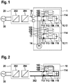
- FIG. 1 shows schematically a battery-operated object 1 which, in the exemplary embodiment shown, comprises two battery modules 10, namely a first battery module 11 and a second battery module 12, as well as a consumer 14.
- the battery-operated object 1 is, for example, an electrically powered small vehicle, such as an eBike or an eScooter.
- the consumer 14 is designed accordingly, for example, as an electric motor.
- the battery modules 10 are set up to be removed from the battery-operated object 1 and reinserted. For this purpose, they comprise a housing 114, which protects the interior of the battery modules 10 from environmental influences, in particular outside the battery-operated object 1.
- the battery modules 10 each include at least one battery cell 110. In the schematic illustration of FIG Figure 1 a single battery cell 110 is shown in each case. However, a battery module 10 preferably comprises a multiplicity of battery cells 110. The battery modules 10 also comprise electrical connections 112, with which they are connected to a common power supply 16 in the battery-operated object 1. All battery modules 10 are connected in parallel to one another via the common power supply 16 and can thus jointly supply the consumer 14 with electrical energy.
- the battery modules 10 furthermore comprise a disconnector 108 and a DC-DC converter 102, which are connected in parallel to one another and thus each connect the battery cell 110 to an electrical connection 112.
- a control unit 104 and a bus module 106 are also provided.
- the control unit 104 is connected to the DC / DC converter 102, the isolating switch 108 and the bus module 106.
- the control unit 104 is set up in particular to control the disconnector 108 and the DC converter 102.
- the isolating switch 108 can be designed, for example, as a relay or semiconductor switch.
- a bus 17 is provided in the battery-operated object 1.
- the bus modules 106 of the battery modules 10 are connected to the bus 17 via bus connections 113.
- the battery-operated object 1 also includes a power connection 18, with which it can be connected to an external power supply unit 20.
- the power connection 18 is in turn connected to the common power supply 16, so that an electrical connection can be established between the external power pack 20 and all battery modules 10 of the battery-operated object 1.
- the battery modules 10 are to be charged so that the external power pack 20 is connected to the power connection 18.
- the external power supply unit 20 comprises, for example, an AC / DC converter 202, which can be connected to an AC voltage source 30, for example a socket, and provides a DC voltage.
- This direct voltage is set via a DC / DC converter 204 to a voltage which is preferably above the nominal voltage of the battery modules 10 and is suitable as an input voltage for the direct current converter 102 of the battery modules 10.
- the isolating switches 108 of the battery modules 10 are opened and a charging current is provided via the DC / DC converter 102, which is controlled by the control unit 104.
- Control by the external power pack 20 is not required; the external power pack 20 merely provides a direct voltage.
- FIG. 2 shows schematically a single battery module 10, which is charged with an external power pack 20.
- the battery module 10 corresponds to the battery modules 10, which are already used in connection with the battery-operated device 1 of Figure 1 and comprises a housing 114, electrical connections 112, a bus connection 113, a DC converter 102, a control unit 104, a circuit breaker 108, a bus module 106 and at least one battery cell 110.
- the external power supply unit 20 also corresponds to that in connection with FIG Figure 1 described external power supply 20 and comprises an AC / DC converter 202 for rectifying an AC voltage of the AC voltage source 30 and a DC / DC converter 204 for adjusting the provided DC voltage.
- the external power pack 20 is connected on an input side to the AC voltage source 30 and on an output side to the electrical connections 112 of the battery module 10. The current flowing during charging is indicated by the arrows with the reference numeral 302.
- the isolating switch 108 of the battery module 10 is opened and a charging current, as indicated by the reference marks 302, is provided via the DC converter 102, which is controlled by the control unit 104.
- Control by the external power pack 20 is not required; the external power pack 20 merely provides a direct voltage.
- FIG Figure 3 shows a charge equalization between two battery modules 10 of the already with reference to FIG Figure 1 described battery-operated object 1.
- the state of charge of the two battery modules 10 is different.
- the first battery module 11 has a lower state of charge than the second battery module 12.
- the states of charge of the two battery modules 10 remain below a predetermined limit value. Is this as in the in Figure 3 If the situation outlined is not the case, a charge equalization is carried out.
- the disconnector 108 of the first battery module 11 is opened and the disconnector 108 of the second battery module 12 is closed.
- the direct current converter 102 of the second battery module 12 is switched off, so that the battery cell 110 of the second battery module is connected directly to the common power supply 16 is.
- a charging current is provided via the DC / DC converter 102, controlled by the control unit 104.
- the current flowing for the charge equalization is sketched with the reference numeral 304 by means of arrows.
- the charging of the at least one battery cell 110 of the first battery module 11 is preferably ended when the state of charge of the first battery module 11 corresponds to that of the second battery module 12.
- the state of charge is then regarded as corresponding to that of the second battery module 12, for example, when the difference is below the predetermined limit value.
- Figure 4 shows the supply of the consumer 14 of the already with reference to Figure 1 described battery-operated object 1 with electrical energy.
- the states of charge of the first battery module 11 and of the second battery module 12 correspond to one another, so that a difference is below the predetermined limit value.
- the battery cells 110 of both battery modules 10 are connected in parallel via the common power supply 16.
- the isolating switches 108 of the two battery modules 10 are each closed. Both battery modules 10 thus contribute equally to supplying consumer 14 with electrical energy.
- the current flowing is in the Figure 4 indicated by arrows with the reference numeral 306.
- the recuperated energy can be absorbed by the battery cells 110 of both battery modules 10 in the same way.
Landscapes
- Engineering & Computer Science (AREA)
- Power Engineering (AREA)
- Charge And Discharge Circuits For Batteries Or The Like (AREA)
- Electric Propulsion And Braking For Vehicles (AREA)
- Secondary Cells (AREA)
Applications Claiming Priority (1)
| Application Number | Priority Date | Filing Date | Title |
|---|---|---|---|
| DE102019219018.9A DE102019219018A1 (de) | 2019-12-06 | 2019-12-06 | Batteriebetriebenes Objekt und Verfahren zum Betreiben des batteriebetriebenen Objekts |
Publications (1)
| Publication Number | Publication Date |
|---|---|
| EP3832843A1 true EP3832843A1 (fr) | 2021-06-09 |
Family
ID=73598758
Family Applications (1)
| Application Number | Title | Priority Date | Filing Date |
|---|---|---|---|
| EP20210053.3A Withdrawn EP3832843A1 (fr) | 2019-12-06 | 2020-11-26 | Objet fonctionnant sur batterie et procédé de fonctionnement de l'objet fonctionnant sur batterie |
Country Status (3)
| Country | Link |
|---|---|
| EP (1) | EP3832843A1 (fr) |
| DE (1) | DE102019219018A1 (fr) |
| TW (1) | TW202130033A (fr) |
Families Citing this family (2)
| Publication number | Priority date | Publication date | Assignee | Title |
|---|---|---|---|---|
| TWI857611B (zh) * | 2022-05-18 | 2024-10-01 | 英屬開曼群島商睿能創意公司 | 具有不同化學材料的電池組的電能儲存裝置及電動車輛 |
| TWI864945B (zh) * | 2023-08-07 | 2024-12-01 | 宏碁股份有限公司 | 電池模組之控制方法 |
Citations (5)
| Publication number | Priority date | Publication date | Assignee | Title |
|---|---|---|---|---|
| DE102008060936A1 (de) * | 2008-12-06 | 2010-06-10 | Daimler Ag | Vorrichtung und Verfahren zum Betreiben einer Batterieeinheit eines Kraftfahrzeugs |
| DE102010037094A1 (de) * | 2010-08-20 | 2012-02-23 | Hochschule Regensburg | Ladungsausgleichsschaltung und Verfahren zur vorausschauenden Steuerung des Ladungsausgleichs |
| DE102015002072A1 (de) * | 2015-02-18 | 2016-08-18 | Audi Ag | Einstellen von Ladungszuständen von Batteriezellen |
| DE102017209282A1 (de) | 2017-06-01 | 2018-12-06 | Robert Bosch Gmbh | Ladevorrichtung zum Laden von Batterien in einem batteriebetriebenen Objekt, batteriebetriebenes Objekt und Verfahren zum Laden von Batterien in einem batteriebetriebenen Objekt |
| US20190288524A1 (en) * | 2018-03-15 | 2019-09-19 | Audi Ag | Battery for a motor vehicle and method for operating a battery |
Family Cites Families (2)
| Publication number | Priority date | Publication date | Assignee | Title |
|---|---|---|---|---|
| KR101221319B1 (ko) * | 2011-02-28 | 2013-01-15 | (주)이미지스테크놀로지 | 배터리팩의 능동형 셀-밸런싱 제어시스템 |
| DE102014107670A1 (de) * | 2014-05-30 | 2015-12-24 | Hochschule Regensburg | Ladungsübertragungsverfahren und -schaltung mit Energiezwischenspeicherung |
-
2019
- 2019-12-06 DE DE102019219018.9A patent/DE102019219018A1/de active Pending
-
2020
- 2020-11-26 EP EP20210053.3A patent/EP3832843A1/fr not_active Withdrawn
- 2020-12-03 TW TW109142620A patent/TW202130033A/zh unknown
Patent Citations (5)
| Publication number | Priority date | Publication date | Assignee | Title |
|---|---|---|---|---|
| DE102008060936A1 (de) * | 2008-12-06 | 2010-06-10 | Daimler Ag | Vorrichtung und Verfahren zum Betreiben einer Batterieeinheit eines Kraftfahrzeugs |
| DE102010037094A1 (de) * | 2010-08-20 | 2012-02-23 | Hochschule Regensburg | Ladungsausgleichsschaltung und Verfahren zur vorausschauenden Steuerung des Ladungsausgleichs |
| DE102015002072A1 (de) * | 2015-02-18 | 2016-08-18 | Audi Ag | Einstellen von Ladungszuständen von Batteriezellen |
| DE102017209282A1 (de) | 2017-06-01 | 2018-12-06 | Robert Bosch Gmbh | Ladevorrichtung zum Laden von Batterien in einem batteriebetriebenen Objekt, batteriebetriebenes Objekt und Verfahren zum Laden von Batterien in einem batteriebetriebenen Objekt |
| US20190288524A1 (en) * | 2018-03-15 | 2019-09-19 | Audi Ag | Battery for a motor vehicle and method for operating a battery |
Also Published As
| Publication number | Publication date |
|---|---|
| DE102019219018A1 (de) | 2021-06-10 |
| TW202130033A (zh) | 2021-08-01 |
Similar Documents
| Publication | Publication Date | Title |
|---|---|---|
| EP2448082B1 (fr) | Système de batterie et procédé de surveillance d'un état de charge d'au moins une batterie rechargeable | |
| EP3209518B1 (fr) | Procédé permettant de faire fonctionner un dispositif d'accumulation d'énergie dans un véhicule automobile et véhicule automobile | |
| EP3092150B1 (fr) | Accumulateur d'énergie électrochimique et procédé d'équilibrage | |
| DE112017004673B4 (de) | Energie-Umwandlungsvorrichtung | |
| DE102009001670A1 (de) | Ladeverfahren und Ladesystem | |
| EP3771019B1 (fr) | Système électrique d'accumulation d'énergie et son procédé de fonctionnement | |
| DE202016105015U1 (de) | Speichersystem zur Speicherung elektrischer Energie | |
| WO2013159821A1 (fr) | Chargeur | |
| WO2016113298A1 (fr) | Batterie haute tension destinée à un véhicule automobile et véhicule automobile | |
| DE102021116525A1 (de) | Vorrichtung und Verfahren zur elektrischen Versorgung eines Niederspannungs-Bordnetzes eines Kraftfahrzeugs, insbesondere Elektrokraftfahrzeugs | |
| EP3470259B1 (fr) | Système d'accumulateurs d'énergie doté d'une pluralité d'accumulateurs d'énergie couplés en parallèle et procédé de fonctionnement d'un système d'accumulateurs d'énergie | |
| DE102018116013B4 (de) | Energieerzeugungsanlage, Wechselrichter und Verfahren zur Vorladung von Gleichspannungs-Zwischenkreisen von Wechselrichtern | |
| DE102020209673A1 (de) | Ladesäule zum Laden eines Stromspeichers eines Elektrofahrzeugs | |
| EP3832843A1 (fr) | Objet fonctionnant sur batterie et procédé de fonctionnement de l'objet fonctionnant sur batterie | |
| EP1332539B1 (fr) | Dispositif chargeur de batteries et procede permettant de charger des batteries a plusieurs blocs de batteries | |
| EP3915825B1 (fr) | Chargeur modulaire destiné à la charge électrique en courant continu d'une batterie d'un véhicule électrique | |
| EP3711133B1 (fr) | Procédé de démarrage autonome d'un dispositif d'alimentation en énergie, onduleur bidirectionnel et dispositif d'alimentation en énergie doté d'un onduleur bidirectionnel | |
| DE102024109502A1 (de) | Laden von und zu einem kraftfahrzeugbatteriesystem über ein mehrfachanschluss-ladesystem | |
| EP4126587A1 (fr) | Procédé, système et dispositif pour alimenter un consommateur en énergie électrique | |
| DE102019209854B4 (de) | Fahrzeugbordnetz | |
| WO2019101443A1 (fr) | Procédé de fonctionnement d'un dispositif accumulateur d'énergie électrique pour véhicule automobile et dispositif accumulateur d'énergie correspondant | |
| EP2582009A1 (fr) | Système de stockage d'énergie avec algorithme de réglage implémenté et procédé de commande de l'état de chargement de ses éléments | |
| DE102010017439A1 (de) | Schaltungsanordnung und Verfahren zum Ausgleich von unterschiedlichen Ladezuständen von Zellen eines Energiespeichers | |
| EP2859639B1 (fr) | Circuit de compensation des charges pour un accumulateur d'énergie et procédé pour la compensation des différences de charge dans un accumulateur d'énergie | |
| DE102020113907A1 (de) | Modulare Ladesäule zum elektrischen Gleichstromladen einer Batterie eines Elektrofahrzeugs |
Legal Events
| Date | Code | Title | Description |
|---|---|---|---|
| PUAI | Public reference made under article 153(3) epc to a published international application that has entered the european phase |
Free format text: ORIGINAL CODE: 0009012 |
|
| STAA | Information on the status of an ep patent application or granted ep patent |
Free format text: STATUS: THE APPLICATION HAS BEEN PUBLISHED |
|
| AK | Designated contracting states |
Kind code of ref document: A1 Designated state(s): AL AT BE BG CH CY CZ DE DK EE ES FI FR GB GR HR HU IE IS IT LI LT LU LV MC MK MT NL NO PL PT RO RS SE SI SK SM TR |
|
| STAA | Information on the status of an ep patent application or granted ep patent |
Free format text: STATUS: REQUEST FOR EXAMINATION WAS MADE |
|
| 17P | Request for examination filed |
Effective date: 20211209 |
|
| RBV | Designated contracting states (corrected) |
Designated state(s): AL AT BE BG CH CY CZ DE DK EE ES FI FR GB GR HR HU IE IS IT LI LT LU LV MC MK MT NL NO PL PT RO RS SE SI SK SM TR |
|
| STAA | Information on the status of an ep patent application or granted ep patent |
Free format text: STATUS: THE APPLICATION IS DEEMED TO BE WITHDRAWN |
|
| 18D | Application deemed to be withdrawn |
Effective date: 20250603 |