EP3832882B1 - Verfahren zur steuerung einer mehrphasigen elektrischen maschine und steuerungssystem - Google Patents
Verfahren zur steuerung einer mehrphasigen elektrischen maschine und steuerungssystem Download PDFInfo
- Publication number
- EP3832882B1 EP3832882B1 EP19213083.9A EP19213083A EP3832882B1 EP 3832882 B1 EP3832882 B1 EP 3832882B1 EP 19213083 A EP19213083 A EP 19213083A EP 3832882 B1 EP3832882 B1 EP 3832882B1
- Authority
- EP
- European Patent Office
- Prior art keywords
- currents
- electrical machine
- controller
- vsd
- phases
- Prior art date
- Legal status (The legal status is an assumption and is not a legal conclusion. Google has not performed a legal analysis and makes no representation as to the accuracy of the status listed.)
- Active
Links
Images

Classifications
-
- H—ELECTRICITY
- H02—GENERATION; CONVERSION OR DISTRIBUTION OF ELECTRIC POWER
- H02P—CONTROL OR REGULATION OF ELECTRIC MOTORS, ELECTRIC GENERATORS OR DYNAMO-ELECTRIC CONVERTERS; CONTROLLING TRANSFORMERS, REACTORS OR CHOKE COILS
- H02P21/00—Arrangements or methods for the control of electric machines by vector control, e.g. by control of field orientation
- H02P21/0003—Control strategies in general, e.g. linear type, e.g. P, PI, PID, using robust control
-
- H—ELECTRICITY
- H02—GENERATION; CONVERSION OR DISTRIBUTION OF ELECTRIC POWER
- H02P—CONTROL OR REGULATION OF ELECTRIC MOTORS, ELECTRIC GENERATORS OR DYNAMO-ELECTRIC CONVERTERS; CONTROLLING TRANSFORMERS, REACTORS OR CHOKE COILS
- H02P21/00—Arrangements or methods for the control of electric machines by vector control, e.g. by control of field orientation
- H02P21/22—Current control, e.g. using a current control loop
-
- H—ELECTRICITY
- H02—GENERATION; CONVERSION OR DISTRIBUTION OF ELECTRIC POWER
- H02P—CONTROL OR REGULATION OF ELECTRIC MOTORS, ELECTRIC GENERATORS OR DYNAMO-ELECTRIC CONVERTERS; CONTROLLING TRANSFORMERS, REACTORS OR CHOKE COILS
- H02P25/00—Arrangements or methods for the control of AC motors characterised by the kind of AC motor or by structural details
- H02P25/16—Arrangements or methods for the control of AC motors characterised by the kind of AC motor or by structural details characterised by the circuit arrangement or by the kind of wiring
- H02P25/22—Multiple windings; Windings for more than three phases
-
- H—ELECTRICITY
- H02—GENERATION; CONVERSION OR DISTRIBUTION OF ELECTRIC POWER
- H02P—CONTROL OR REGULATION OF ELECTRIC MOTORS, ELECTRIC GENERATORS OR DYNAMO-ELECTRIC CONVERTERS; CONTROLLING TRANSFORMERS, REACTORS OR CHOKE COILS
- H02P27/00—Arrangements or methods for the control of AC motors characterised by the kind of supply voltage
- H02P27/04—Arrangements or methods for the control of AC motors characterised by the kind of supply voltage using variable-frequency supply voltage, e.g. inverter or converter supply voltage
-
- H—ELECTRICITY
- H02—GENERATION; CONVERSION OR DISTRIBUTION OF ELECTRIC POWER
- H02P—CONTROL OR REGULATION OF ELECTRIC MOTORS, ELECTRIC GENERATORS OR DYNAMO-ELECTRIC CONVERTERS; CONTROLLING TRANSFORMERS, REACTORS OR CHOKE COILS
- H02P27/00—Arrangements or methods for the control of AC motors characterised by the kind of supply voltage
- H02P27/04—Arrangements or methods for the control of AC motors characterised by the kind of supply voltage using variable-frequency supply voltage, e.g. inverter or converter supply voltage
- H02P27/06—Arrangements or methods for the control of AC motors characterised by the kind of supply voltage using variable-frequency supply voltage, e.g. inverter or converter supply voltage using DC to AC converters or inverters
-
- H—ELECTRICITY
- H02—GENERATION; CONVERSION OR DISTRIBUTION OF ELECTRIC POWER
- H02P—CONTROL OR REGULATION OF ELECTRIC MOTORS, ELECTRIC GENERATORS OR DYNAMO-ELECTRIC CONVERTERS; CONTROLLING TRANSFORMERS, REACTORS OR CHOKE COILS
- H02P27/00—Arrangements or methods for the control of AC motors characterised by the kind of supply voltage
- H02P27/04—Arrangements or methods for the control of AC motors characterised by the kind of supply voltage using variable-frequency supply voltage, e.g. inverter or converter supply voltage
- H02P27/06—Arrangements or methods for the control of AC motors characterised by the kind of supply voltage using variable-frequency supply voltage, e.g. inverter or converter supply voltage using DC to AC converters or inverters
- H02P27/08—Arrangements or methods for the control of AC motors characterised by the kind of supply voltage using variable-frequency supply voltage, e.g. inverter or converter supply voltage using DC to AC converters or inverters with pulse width modulation
- H02P27/12—Arrangements or methods for the control of AC motors characterised by the kind of supply voltage using variable-frequency supply voltage, e.g. inverter or converter supply voltage using DC to AC converters or inverters with pulse width modulation pulsing by guiding the flux vector, current vector or voltage vector on a circle or a closed curve, e.g. for direct torque control
Definitions
- the present disclosure generally relates to multi-phase electrical machines and in particular to a method of controlling a multi-phase electrical machine.
- the control of a multi-phase machine using the VSD approach requires the execution of some basic transformations in the machine currents.
- the VSD transform provides mutually orthonormal subspaces of the fundamental frequency and lower harmonics.
- the six measured currents are typically first transformed to the ⁇ , the xy, and the o 1 o 2 subspaces by VSD transformation, and then to the dq domain.
- the o 1 o 2 subspace is the subspace for all the zero sequence harmonics.
- the 3 rd harmonic is zero if the two neutrals are not connected, and if the neutrals are connected, the o 1 o 2 subspace is the subspace for the 3 rd harmonic.
- the voltage references for each different harmonic subspace can be calculated.
- information of all the machine currents is needed. Therefore, a central controller which receives the measured currents and generates the voltage references or control signals is required. Afterward, each drive receives control signals and produces the switching pulses independently.
- EP 1 732 204 A1 discloses a method that involves providing a converter unit for each set of stator windings. Currents of phase windings of each set of stator windings are measured. A regulating device is provided for each converter unit, and each converter unit is driven by a drive signal of the associated regulating device independently of regulating devices of the other converter units. The drive signal is formed in the regulating device from the measured currents of each set of stator windings.
- VSD approach cannot be applied to cases where a master-follower configuration is required for improved redundancy.
- a communication link of high bandwidth is needed for exchanging information about the phase currents from the master to the follower, and vice versa.
- the main controller is subjected to a fault, the remaining drive(s) cannot continue to operate and drive the healthy winding set(s) of the electrical machine because the machine is centrally controlled.
- an object of the present disclosure is to provide a method of controlling a multi-phase electrical machine which solves, or at least mitigates, the problems of the prior art.
- the method for each controller comprises: a) obtaining measured currents only of the set of three phases of the electrical machine controlled by the respective controller, b) estimating all currents of all the other sets of three phases of the electrical machine, which are controlled by the other controllers, c) transforming the measured currents and all the estimated currents using vector space decomposition, VSD, to obtain a set of VSD currents, and d) controlling the corresponding power converter based on the VSD currents.
- the coupling effects among the winding sets of the 3n-phase electrical machine may thereby be minimised, even when a master-follower configuration is used.
- the power converters can operate independently without the need for a central controller or a communications link.
- the fault tolerance is improved in case the main controller goes out of operation, and enables current sharing.
- the estimated currents are components corresponding to all the other sets of three phases controlled by the other controllers.
- the estimated currents may be represented by a vector in the rotor reference frame or in the stator reference frame.
- step b) all the currents are estimated using a current reference vector of the fundamental frequency subspace for all the power converters obtained by VSD transformation and the measured currents to obtain the estimated currents.
- the estimated currents are obtained by subtracting the measured currents from the current reference vector of the fundamental frequency subspace transformed to the stator reference frame and multiplied by n.
- One embodiment comprises combining the VSD currents with setpoint current values to obtain control errors, and obtaining control signals based on the control errors, wherein in step d) the controlling is based on the control signals.
- the currents of all the 3*(n-1) windings can be estimated summed together.
- the estimated summed currents may then be shared based on the power sharing of the power converters, which is known in all the controllers.
- Vector components of the estimated summed currents may hence be identified and associated with different power converters based on the power sharing of the power converters. Based on this identification and association, the VSD transform may be performed in step c).
- a computer program comprising computer code which when executed by processing circuitry of a control system causes the control system to perform the steps of the method according to the first aspect.
- an electrical machine system comprising: a 3n-phase electrical machine, n power converters configured to be connected to the electrical machine for controlling respective sets of three phases of the electrical machine, and a control system according to the second aspect, wherein each of the n controllers is configured to control a respective power converter.
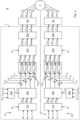
- the control system 1 comprises a plurality of controllers C1 to Cn.
- Each controller C1 to Cn is configured to control a respective set of phases of the multi-phase machine by means of a respective power converter.
- Each controller C1 to Cn may for example be configured to control a respective set of three phases of the electrical machine.
- The/each storage medium may for example be embodied as a memory, such as a random access memory (RAM), a read-only memory (ROM), an erasable programmable read-only memory (EPROM), or an electrically erasable programmable read-only memory (EEPROM) and more particularly as a non-volatile storage medium of a device in an external memory such as a USB (Universal Serial Bus) memory or a Flash memory, such as a compact Flash memory.
- RAM random access memory
- ROM read-only memory
- EPROM erasable programmable read-only memory
- EEPROM electrically erasable programmable read-only memory
- Each controller C1 to Cn may comprise a communications interface including an input device and an output device.
- the input device is configured to receive respective measured currents of electrical phases of the electrical machine that are controlled by the controller in question.
- the measured currents can be obtained from one or more current sensors arranged to measure the currents of the corresponding electrical phases of the electrical machine.
- the measured currents are typically stator currents.
- the controllers are configured to process the respective measured currents to obtain control signals.
- Each output device is configured to transmit the control signals to control the corresponding power converter.
- the first controller C1 comprises a first current estimator 13a.
- the second controller C2 comprises a second current estimator 13b.
- the first current estimator 13a is configured to estimate all the currents of all the other sets of three phases of the electrical machine 7 than those controlled by the first controller C1.
- the first current estimator 13a is configured to estimate the measured currents ia,2, ib,2 and ic,2, sent by the current sensors to the second controller C2, however in the stator reference frame or in the rotor reference frame.
- i ⁇ VSD ⁇ is selected to be i dq , ⁇ ⁇ transformed to the stator reference frame.
- i dq , ⁇ ⁇ is the current reference vector of the fundamental frequency subspace in the rotor reference frame i.e. the current reference vector for the ⁇ subspace in the rotor reference frame, that is the dq-frame.
- i ⁇ , iDTP ⁇ is the current vector of the i:th set of measured currents in the stator reference frame, i.e. the ⁇ -frame. This current vector is hence not in the VSD domain.
- the current reference vector of the fundamental frequency subspace i dq , ⁇ ⁇ transformed to the stator reference frame is hence equal to the sum of the measured currents in the stator reference frame for each of the n controllers, divided by n.
- the vector idq,1 consists of the rotor reference frame currents id,1, iq,1, and io,1.
- the transformation from the rotor reference frame to the stator reference frame can be performed based on the electrical angle ⁇ m, which is an input to both current estimators 13a and 13b.
- the vector idq,2 consists of the rotor reference frame currents id,2, iq,2, and io,2.
- all the currents of the set of three phases controlled by the second controller C2 may be estimated by the first controller C1 and all the currents of the set of three phases controlled by the first controller C1 may be estimated by the second controller C2.
- the first current estimator 13a is configured to transform all the estimated currents to the rotor reference frame.
- the second current estimator 13b is configured to transform all the estimated currents to the rotor reference frame.
- the estimated currents from the first current estimator 13a after having been transformed from the stator reference frame to the rotor reference frame are denoted idq, 2.
- the estimated currents from the second current estimator 13b after having been transformed from the stator reference frame to the rotor reference frame are denoted îdq , 1.
- the estimated currents îdq, 1 from the second current estimator 13b are provided to a second VSD transform block 15b together with the rotor reference frame currents id,2, iq,2, and io,2, associated with the second controller C2.
- the second VSD transform block 15b if configured to transform these currents using the VSD transform to obtain a set of VSD currents.
- the control of the second power converter 3b is based on the set of VSD currents obtained from the second VSD transform block 15b.
- the VSD currents are sent from the first VSD transform block 15a to respective first combiners 17a to combine each VSD current with a corresponding setpoint current value in the VSD domain, i.e. in the corresponding subspaces.
- the setpoint current value i*d, ⁇ denotes the setpoint current value in the ⁇ -subspace of the VSD transform for the d-component of the current in the rotor reference frame.
- Each first combiner 17a determines the difference between the corresponding VSD current and the corresponding setpoint current value to obtain the control error.
- the VSD currents are sent from the second VSD transform block 15b to respective second combiners 17b to combine each VSD current with a corresponding setpoint current value in the VSD domain, i.e. in the corresponding subspaces.
- the setpoint current values provided to the second combiners 17b are the same as for the first combiners 17a.
- Each second combiner 17b determines the difference between the corresponding VSD current and the corresponding setpoint current value to obtain the control error.
- the control errors from the first combiners 17a are provided to respective first current controllers 19a.
- the first current controllers 19a may be proportional-integral (PI) regulators.
- the first current controllers 19a process the control errors from the first combiners 17a to obtain respective control signals.
- the control signals are in the present example voltage references. For example, u d , ⁇ ⁇ denotes the d-component voltage reference in the ⁇ subspace, and u d , xy ⁇ denotes the d-component voltage reference frame in the xy subspace.
- the control errors from the second combiners 17b are provided to respective second current controllers 19b.
- the second current controllers 19b may be PI-regulators.
- the second current controllers 19b process the control errors from the second combiners 17b to obtain respective control signals.
- the control signals are in this example voltage references.
- the first current regulators 19a and the second current regulators 19b may be configured to operate completely independently from each other.
- the exemplified control system 1 comprises a first inverse transform block 21a and a second inverse transform block 21b.
- the first inverse transform block 21a is configured transform the voltage references output by the first current regulators 19a to the stator reference frame.
- the voltage references are at this stage still in the VSD domain.
- the output from the first inverse transform block 21a are the voltage reference u ⁇ ⁇ in the stator reference frame in the ⁇ subspace, the voltage reference u xy ⁇ in the stator reference frame in the xy subspace, and the voltage reference u o 12 ⁇ in the stator reference frame in the o1o2 subspace.
- the second inverse transform block 21b is configured transform the voltage references output by the second current regulators 19b to the stator reference frame.
- the voltage references are at this stage still in the VSD domain.
- the output from the second inverse transform block 21b are the voltage reference u ⁇ ⁇ in the stator reference frame in the ⁇ subspace, the voltage reference u xy ⁇ in the stator reference frame in the xy subspace, and the voltage reference u o 12 ⁇ in the stator reference frame in the o1o2 subspace.
- the first inverse transform block 21a may be configured to perform an inverse Park transform.
- the second inverse transform block 21b may be configured to perform an inverse Park transform.
- the voltage references in the stator reference frame obtained from the first inverse transform block 21a are provided to a first inverse VSD transform block 23a configured to transform the voltage references from the VSD domain to the abc reference frame to obtain abc voltage references u a , 1 ⁇ , u b , 1 ⁇ , and u c , 1 ⁇ for the phases controlled by the first power converter 3a.
- the abc voltage references u a , 1 ⁇ , u b , 1 ⁇ , and u c , 1 ⁇ are provided to the first controller 3a, which based on the abc voltage references u a , 1 ⁇ , u b .1 ⁇ , and u c .1 ⁇ controls the corresponding set of three phases of the electrical machine 7.
- the abc voltage references u a , 1 ⁇ , u b , 1 ⁇ , and u c , 1 ⁇ are used for modulating switches of the first controller 3a to generate voltages u a ,1 , u b ,1 , and u c, 1 for controlling the set of windings controlled by the first controller 3a.
- the voltage references in the stator reference frame obtained from the second inverse transform block 21b are provided to a second inverse VSD transform block 23b configured to transform the voltage references from the VSD domain to the abc reference frame to obtain abc voltage references u a , 2 ⁇ , u b , 2 ⁇ , and u c , 2 ⁇ for the phases controlled by the second power converter 3b.
- the abc voltage references u a , 2 ⁇ , u b , 2 ⁇ , and u b , 2 ⁇ are provided to the second controller 3b, which based on the abc voltage references u a , 2 ⁇ , u b , 2 ⁇ , and u c , 2 ⁇ controls the corresponding set of three phases of the electrical machine 7.
- each controller may obtain the measured currents associated with the other controllers. This may for example be achieved by means of a communications link such as a low bandwidth communications link, between the controllers. The sum of these measured currents may be compared with the sum of the estimated currents.
- the control system may be configured to conclude, on the basis that the measured currents differs from the estimated currents by more than a threshold value, that a fault is present in the electrical machine or in the communications link.
Landscapes
- Engineering & Computer Science (AREA)
- Power Engineering (AREA)
- Control Of Ac Motors In General (AREA)
Claims (12)
- Verfahren zum Steuern einer elektrischen 3n-Phasen-Maschine (7) mittels n Leistungsumrichtern (3a, 3b), die jeweils durch eine jeweilige Steuerung (C1,...Cn) gesteuert werden, wobei n eine ganze Zahl gleich oder größer als 2 ist und jeder Leistungsumrichter (3a, 3b) dazu ausgelegt ist, einen jeweiligen Satz von drei Phasen der elektrischen Maschine (7) mit Leistung zu versorgen, wobei das Verfahren für jede Steuerung (C1,...Cn) Folgendes umfasst:a) Erhalten gemessener Ströme (ia,1, ib,1, ic,1, ia,2, ib,2, ic,2) des Satzes von drei Phasen der elektrischen Maschine (7), die durch die jeweilige Steuerung (C1,...Cn) gesteuert werden, dadurch gekennzeichnet, dass das Verfahren für jede Steuerung ferner Folgendes umfasst:b) Schätzen aller Ströme (îdq, 2, îdq, 1) aller anderen Sätze von drei Phasen der elektrischen Maschine (7), die von den anderen Steuerungen (C1,...Cn) gesteuert werden,c) Transformieren der gemessenen Ströme (ia,1, ib,1, ic,1, ia,2, ib,2, ic,2) und aller geschätzten Ströme (îdq, 2, îdq, 1) unter Verwendung von Vektorraumzerlegung, VSD, um einen Satz von VSD-Strömen zu erhalten, undd) Steuern des entsprechenden Leistungsumrichters (3a, 3b) basierend auf den VSD-Strömen.
- Verfahren nach Anspruch 1, wobei in Schritt b) alle Ströme unter Verwendung eines Stromreferenzvektors des Grundfrequenzteilraums (

- Verfahren nach Anspruch 2, wobei die geschätzten Ströme durch Subtrahieren der gemessenen Ströme (ia,1, ib,1, ic,1, ia,2, ib,2, ic,2) von dem Stromreferenzvektor des Grundfrequenzteilraums (

- Verfahren nach einem der vorhergehenden Ansprüche, umfassend Transformieren der gemessenen Ströme (ia,1, ib,1, ic,1, ia,2, ib,2, ic,2) und den geschätzten Strömen zu einem Rotorreferenzrahmen und Verwenden dieser in Schritt c), um die VSD-Ströme zu erhalten.
- Verfahren nach einem der vorhergehenden Ansprüche, umfassend Kombinieren der VSD-Ströme mit Sollstromwerten, um Steuerfehler zu erhalten, und Erhalten von Steuersignalen basierend auf den Steuerfehlern, wobei in Schritt d) das Steuern auf den Steuersignalen basiert.
- Verfahren nach Anspruch 5, umfassend Transformieren der Steuersignale von einem Rotorreferenzrahmen in den abc-Referenzrahmen unter Verwendung von inverser VSD, um die Steuersignale in dem abc-Referenzrahmen nur für die betreffende Steuerung zu erhalten.
- Verfahren nach einem der vorhergehenden Ansprüche, wobei n gleich 2 ist.
- Verfahren nach einem der vorhergehenden Ansprüche, wobei in Schritt a) die erhaltenen gemessenen Ströme (ia,1, ib,1, ic,1, ia,2, ib,2, ic,2) nur von dem Satz von drei Phasen der elektrischen Maschine (7) stammen, die von der jeweiligen Steuerung (C1,...Cn) gesteuert werden.
- Verfahren nach einem der Ansprüche 1-7, wobei das Verfahren für jede Steuerung (C1,...Cn) ferner Folgendes umfasst:Erhalten gemessener Ströme des Satzes von drei Phasen der elektrischen Maschine, die von der anderen Steuerung oder den anderen Steuerungen gesteuert werden,Vergleichen der Summe der gemessenen Ströme des Satzes von drei Phasen der elektrischen Maschine (7), die von der anderen Steuerung oder den anderen Steuerungen (C1,...CN) gesteuert wird, mit der Summe der geschätzten Ströme, undauf der Grundlage, dass sich die gemessenen Ströme von den geschätzten Strömen um mehr als einen Schwellenwert unterscheiden, Folgern, dass ein Fehler vorliegt.
- Computerprogramm, das Computercode umfasst, der, wenn er durch eine Verarbeitungsschaltungsanordnung eines Steuersystems (1) ausgeführt wird, das Steuersystem (1) veranlasst, die Schritte des Verfahrens nach einem der Ansprüche 1-9 durchzuführen.
- Steuersystem (1) zum Steuern einer elektrischen 3n-Phasen-Maschine (7) mittels n Leistungsumrichtern (3a, 3b), wobei n eine ganze Zahl gleich oder größer als 2 ist, wobei jeder Leistungsumrichter (3a, 3b) dazu ausgelegt ist, einen jeweiligen Satz von drei Phasen zu steuern, wobei das Steuersystem (1) n Steuerungen (C1,...Cn) umfasst, die jeweils dazu ausgelegt sind, einen jeweiligen Leistungsumrichter (3a, 3b) durch Durchführen der Schritte nach einem der Ansprüche 1-9 zu steuern.
- Elektrisches Maschinensystem (9), umfassend:eine elektrische 3n-Phasen-Maschine (7),n Leistungsumrichter (3a, 3b), die dazu ausgelegt sind, mit der elektrischen Maschine (7) verbunden zu werden, um jeweilige Sätze von drei Phasen der elektrischen Maschine (7) zu steuern, undein Steuersystem (1) nach Anspruch 11, wobei jede der n Steuerungen (C1,...Cn) dazu ausgelegt ist, einen jeweiligen Leistungsumrichter (3a, 3b) zu steuern.
Priority Applications (3)
| Application Number | Priority Date | Filing Date | Title |
|---|---|---|---|
| EP19213083.9A EP3832882B1 (de) | 2019-12-03 | 2019-12-03 | Verfahren zur steuerung einer mehrphasigen elektrischen maschine und steuerungssystem |
| US17/107,246 US11527979B2 (en) | 2019-12-03 | 2020-11-30 | Method of controlling a multi-phase electrical machine |
| CN202011403597.6A CN112910345B (zh) | 2019-12-03 | 2020-12-02 | 控制多相电机的方法 |
Applications Claiming Priority (1)
| Application Number | Priority Date | Filing Date | Title |
|---|---|---|---|
| EP19213083.9A EP3832882B1 (de) | 2019-12-03 | 2019-12-03 | Verfahren zur steuerung einer mehrphasigen elektrischen maschine und steuerungssystem |
Publications (3)
| Publication Number | Publication Date |
|---|---|
| EP3832882A1 EP3832882A1 (de) | 2021-06-09 |
| EP3832882C0 EP3832882C0 (de) | 2025-07-09 |
| EP3832882B1 true EP3832882B1 (de) | 2025-07-09 |
Family
ID=68766557
Family Applications (1)
| Application Number | Title | Priority Date | Filing Date |
|---|---|---|---|
| EP19213083.9A Active EP3832882B1 (de) | 2019-12-03 | 2019-12-03 | Verfahren zur steuerung einer mehrphasigen elektrischen maschine und steuerungssystem |
Country Status (3)
| Country | Link |
|---|---|
| US (1) | US11527979B2 (de) |
| EP (1) | EP3832882B1 (de) |
| CN (1) | CN112910345B (de) |
Families Citing this family (1)
| Publication number | Priority date | Publication date | Assignee | Title |
|---|---|---|---|---|
| CN114584029B (zh) * | 2022-05-07 | 2022-07-22 | 电子科技大学(深圳)高等研究院 | 抑制对称六相交流电机零序电流的方法及系统 |
Citations (1)
| Publication number | Priority date | Publication date | Assignee | Title |
|---|---|---|---|---|
| EP1732204A1 (de) * | 2005-06-08 | 2006-12-13 | ABB Schweiz AG | Verfahren zum Betrieb einer rotierenden elektrischen Maschine sowie Vorrichtung zur Durchführung des Verfahrens |
Family Cites Families (11)
| Publication number | Priority date | Publication date | Assignee | Title |
|---|---|---|---|---|
| KR100371369B1 (ko) * | 2000-08-18 | 2003-02-06 | 엘지산전 주식회사 | 유도 전동기의 벡터 제어 시스템 |
| JP3896047B2 (ja) * | 2002-07-26 | 2007-03-22 | 株式会社豊田中央研究所 | モータ駆動制御装置 |
| JP5504878B2 (ja) * | 2009-12-24 | 2014-05-28 | 株式会社デンソー | 車両用発電機 |
| JP6211443B2 (ja) * | 2014-03-14 | 2017-10-11 | 日立オートモティブシステムズ株式会社 | 電動モータの制御装置 |
| US9712096B2 (en) * | 2014-04-28 | 2017-07-18 | Mitsubishi Electric Corporation | Control apparatus and control method for AC rotary machine, and electric power steering apparatus |
| US10075107B2 (en) * | 2015-11-03 | 2018-09-11 | Nxp Usa, Inc. | Method and apparatus for motor lock or stall detection |
| EP3264593B1 (de) * | 2016-06-30 | 2018-10-17 | Siemens Aktiengesellschaft | Steuerungsanordnung für einen generator |
| CN107070361B (zh) * | 2017-03-30 | 2019-02-12 | 沈阳工业大学 | 一种降低六相电动机共模电压的svpwm控制方法 |
| DE102018207583A1 (de) * | 2018-05-16 | 2019-11-21 | Zf Friedrichshafen Ag | Verfahren, Computerprogrammprodukt und System zum Betreiben einer Asynchronmaschine sowie Asynchronmaschine |
| CN109617496B (zh) * | 2019-02-18 | 2021-09-28 | 哈尔滨工程大学 | 一种基于同轴线双矢量合成中间矢量的六相svpwm方法 |
| CN109713976B (zh) * | 2019-02-22 | 2020-09-25 | 清华大学 | 十二相永磁同步电机无速度传感器控制方法及装置 |
-
2019
- 2019-12-03 EP EP19213083.9A patent/EP3832882B1/de active Active
-
2020
- 2020-11-30 US US17/107,246 patent/US11527979B2/en active Active
- 2020-12-02 CN CN202011403597.6A patent/CN112910345B/zh active Active
Patent Citations (1)
| Publication number | Priority date | Publication date | Assignee | Title |
|---|---|---|---|---|
| EP1732204A1 (de) * | 2005-06-08 | 2006-12-13 | ABB Schweiz AG | Verfahren zum Betrieb einer rotierenden elektrischen Maschine sowie Vorrichtung zur Durchführung des Verfahrens |
Also Published As
| Publication number | Publication date |
|---|---|
| CN112910345B (zh) | 2024-06-21 |
| CN112910345A (zh) | 2021-06-04 |
| US20210167708A1 (en) | 2021-06-03 |
| US11527979B2 (en) | 2022-12-13 |
| EP3832882C0 (de) | 2025-07-09 |
| EP3832882A1 (de) | 2021-06-09 |
Similar Documents
| Publication | Publication Date | Title |
|---|---|---|
| Habibullah et al. | Finite-state predictive torque control of induction motor supplied from a three-level NPC voltage source inverter | |
| CN103378742B (zh) | 变流器系统及其控制方法 | |
| US11171594B2 (en) | Control apparatus for multiple-winding rotating electric machine | |
| US11271508B2 (en) | Power conversion device, motor driving system, and control method | |
| Levi et al. | Vector control schemes for series-connected six-phase two-motor drive systems | |
| US10312838B2 (en) | Drive system | |
| DE112010002402T5 (de) | Steuerungsvorrichtung für eine Elektromotorantriebsvorrichtung | |
| DE102011002743A1 (de) | Verfahren, Systeme und Vorrichtung zur Synchron-Stromregelung einer Fünf-Phasen-Maschine | |
| Abdel-Khalik et al. | Calculation of derating factors based on steady-state unbalanced multiphase induction machine model under open phase (s) and optimal winding currents | |
| DE102012212308A1 (de) | Verfahren, Systeme und Vorrichtung zum Anpassen eines Modulationsindexes zur Verbesserung der Linearität von Phasenspannungsbefehlen | |
| Singh et al. | A simple indirect field-oriented control scheme for multiconverter-fed induction motor | |
| EP3709505B1 (de) | Verfahren zur steuerung einer mehrphasigen elektrischen maschine | |
| US11527979B2 (en) | Method of controlling a multi-phase electrical machine | |
| CN101904086B (zh) | 用于运行回转式电机的方法 | |
| EP4415245A1 (de) | Leistungsumwandlungsvorrichtung und steuerungsvorrichtung | |
| Khadar et al. | Fault-tolerant sensorless sliding mode control by parameters estimation of an open-end winding five-phase induction motor | |
| Ali et al. | Finite control set model predictive direct current control strategy with constraints applying to drive three-phase induction motor. | |
| EP3713079A1 (de) | Steuerung einer mehrphasigen maschine | |
| Pandian et al. | Simulation and analysis of multilevel inverter fed induction motor drive | |
| CN108429502B (zh) | 永磁同步电机的参数辨识方法、装置及系统 | |
| Ouanouki et al. | Predictive Control Strategy for Two Five-Phase Permanent Magnet Synchronous Motors Connected in Series Powered by A Single Inverter. | |
| Khadar Saad | Stator Resistance Compensator Based on Model Reference Adaptive System Scheme for Sensor-Less Direct Torque Control of an Open End-Winding Induction Motor with First Coil Faults | |
| Eldeeb et al. | Enhanced electromechanical modeling of asymmetrical dual three-phase IPMSM drives | |
| Khadar et al. | Real-time digital simulation for Sensorless control scheme based on reduced-order sliding mode observer for dual star induction motor | |
| Behera et al. | Multilevel Inverter‐Fed Closed Loop Control and Analysis of Induction Motor Drive |
Legal Events
| Date | Code | Title | Description |
|---|---|---|---|
| PUAI | Public reference made under article 153(3) epc to a published international application that has entered the european phase |
Free format text: ORIGINAL CODE: 0009012 |
|
| STAA | Information on the status of an ep patent application or granted ep patent |
Free format text: STATUS: THE APPLICATION HAS BEEN PUBLISHED |
|
| AK | Designated contracting states |
Kind code of ref document: A1 Designated state(s): AL AT BE BG CH CY CZ DE DK EE ES FI FR GB GR HR HU IE IS IT LI LT LU LV MC MK MT NL NO PL PT RO RS SE SI SK SM TR |
|
| STAA | Information on the status of an ep patent application or granted ep patent |
Free format text: STATUS: REQUEST FOR EXAMINATION WAS MADE |
|
| 17P | Request for examination filed |
Effective date: 20211209 |
|
| RBV | Designated contracting states (corrected) |
Designated state(s): AL AT BE BG CH CY CZ DE DK EE ES FI FR GB GR HR HU IE IS IT LI LT LU LV MC MK MT NL NO PL PT RO RS SE SI SK SM TR |
|
| STAA | Information on the status of an ep patent application or granted ep patent |
Free format text: STATUS: EXAMINATION IS IN PROGRESS |
|
| 17Q | First examination report despatched |
Effective date: 20230704 |
|
| GRAP | Despatch of communication of intention to grant a patent |
Free format text: ORIGINAL CODE: EPIDOSNIGR1 |
|
| STAA | Information on the status of an ep patent application or granted ep patent |
Free format text: STATUS: GRANT OF PATENT IS INTENDED |
|
| INTG | Intention to grant announced |
Effective date: 20250217 |
|
| GRAS | Grant fee paid |
Free format text: ORIGINAL CODE: EPIDOSNIGR3 |
|
| GRAA | (expected) grant |
Free format text: ORIGINAL CODE: 0009210 |
|
| STAA | Information on the status of an ep patent application or granted ep patent |
Free format text: STATUS: THE PATENT HAS BEEN GRANTED |
|
| AK | Designated contracting states |
Kind code of ref document: B1 Designated state(s): AL AT BE BG CH CY CZ DE DK EE ES FI FR GB GR HR HU IE IS IT LI LT LU LV MC MK MT NL NO PL PT RO RS SE SI SK SM TR |
|
| REG | Reference to a national code |
Ref country code: GB Ref legal event code: FG4D |
|
| REG | Reference to a national code |
Ref country code: CH Ref legal event code: EP |
|
| REG | Reference to a national code |
Ref country code: IE Ref legal event code: FG4D |
|
| REG | Reference to a national code |
Ref country code: DE Ref legal event code: R096 Ref document number: 602019072237 Country of ref document: DE |
|
| RAP4 | Party data changed (patent owner data changed or rights of a patent transferred) |
Owner name: ABB SCHWEIZ AG |
|
| U01 | Request for unitary effect filed |
Effective date: 20250805 |
|
| U07 | Unitary effect registered |
Designated state(s): AT BE BG DE DK EE FI FR IT LT LU LV MT NL PT RO SE SI Effective date: 20250814 |
|
| PG25 | Lapsed in a contracting state [announced via postgrant information from national office to epo] |
Ref country code: IS Free format text: LAPSE BECAUSE OF FAILURE TO SUBMIT A TRANSLATION OF THE DESCRIPTION OR TO PAY THE FEE WITHIN THE PRESCRIBED TIME-LIMIT Effective date: 20251109 |
|
| PG25 | Lapsed in a contracting state [announced via postgrant information from national office to epo] |
Ref country code: NO Free format text: LAPSE BECAUSE OF FAILURE TO SUBMIT A TRANSLATION OF THE DESCRIPTION OR TO PAY THE FEE WITHIN THE PRESCRIBED TIME-LIMIT Effective date: 20251009 |
|
| PG25 | Lapsed in a contracting state [announced via postgrant information from national office to epo] |
Ref country code: HR Free format text: LAPSE BECAUSE OF FAILURE TO SUBMIT A TRANSLATION OF THE DESCRIPTION OR TO PAY THE FEE WITHIN THE PRESCRIBED TIME-LIMIT Effective date: 20250709 |
|
| PG25 | Lapsed in a contracting state [announced via postgrant information from national office to epo] |
Ref country code: GR Free format text: LAPSE BECAUSE OF FAILURE TO SUBMIT A TRANSLATION OF THE DESCRIPTION OR TO PAY THE FEE WITHIN THE PRESCRIBED TIME-LIMIT Effective date: 20251010 |
|
| PG25 | Lapsed in a contracting state [announced via postgrant information from national office to epo] |
Ref country code: PL Free format text: LAPSE BECAUSE OF FAILURE TO SUBMIT A TRANSLATION OF THE DESCRIPTION OR TO PAY THE FEE WITHIN THE PRESCRIBED TIME-LIMIT Effective date: 20250709 |
|
| PG25 | Lapsed in a contracting state [announced via postgrant information from national office to epo] |
Ref country code: RS Free format text: LAPSE BECAUSE OF FAILURE TO SUBMIT A TRANSLATION OF THE DESCRIPTION OR TO PAY THE FEE WITHIN THE PRESCRIBED TIME-LIMIT Effective date: 20251009 |
|
| PG25 | Lapsed in a contracting state [announced via postgrant information from national office to epo] |
Ref country code: ES Free format text: LAPSE BECAUSE OF FAILURE TO SUBMIT A TRANSLATION OF THE DESCRIPTION OR TO PAY THE FEE WITHIN THE PRESCRIBED TIME-LIMIT Effective date: 20250709 |
|
| U20 | Renewal fee for the european patent with unitary effect paid |
Year of fee payment: 7 Effective date: 20251230 |
|
| PG25 | Lapsed in a contracting state [announced via postgrant information from national office to epo] |
Ref country code: SM Free format text: LAPSE BECAUSE OF FAILURE TO SUBMIT A TRANSLATION OF THE DESCRIPTION OR TO PAY THE FEE WITHIN THE PRESCRIBED TIME-LIMIT Effective date: 20250709 |
|
| PG25 | Lapsed in a contracting state [announced via postgrant information from national office to epo] |
Ref country code: CZ Free format text: LAPSE BECAUSE OF FAILURE TO SUBMIT A TRANSLATION OF THE DESCRIPTION OR TO PAY THE FEE WITHIN THE PRESCRIBED TIME-LIMIT Effective date: 20250709 |
|
| PG25 | Lapsed in a contracting state [announced via postgrant information from national office to epo] |
Ref country code: SK Free format text: LAPSE BECAUSE OF FAILURE TO SUBMIT A TRANSLATION OF THE DESCRIPTION OR TO PAY THE FEE WITHIN THE PRESCRIBED TIME-LIMIT Effective date: 20250709 |
|
| PLBE | No opposition filed within time limit |
Free format text: ORIGINAL CODE: 0009261 |
|
| STAA | Information on the status of an ep patent application or granted ep patent |
Free format text: STATUS: NO OPPOSITION FILED WITHIN TIME LIMIT |