EP3832934A1 - Synchronisationssignalübertragungsverfahren und endgerät - Google Patents
Synchronisationssignalübertragungsverfahren und endgerät Download PDFInfo
- Publication number
- EP3832934A1 EP3832934A1 EP19840206.7A EP19840206A EP3832934A1 EP 3832934 A1 EP3832934 A1 EP 3832934A1 EP 19840206 A EP19840206 A EP 19840206A EP 3832934 A1 EP3832934 A1 EP 3832934A1
- Authority
- EP
- European Patent Office
- Prior art keywords
- synchronization signal
- psss
- ssss
- sidelink synchronization
- signal block
- Prior art date
- Legal status (The legal status is an assumption and is not a legal conclusion. Google has not performed a legal analysis and makes no representation as to the accuracy of the status listed.)
- Granted
Links
Images


Classifications
-
- H—ELECTRICITY
- H04—ELECTRIC COMMUNICATION TECHNIQUE
- H04L—TRANSMISSION OF DIGITAL INFORMATION, e.g. TELEGRAPHIC COMMUNICATION
- H04L5/00—Arrangements affording multiple use of the transmission path
- H04L5/003—Arrangements for allocating sub-channels of the transmission path
- H04L5/0053—Allocation of signalling, i.e. of overhead other than pilot signals
-
- H—ELECTRICITY
- H04—ELECTRIC COMMUNICATION TECHNIQUE
- H04W—WIRELESS COMMUNICATION NETWORKS
- H04W56/00—Synchronisation arrangements
- H04W56/001—Synchronization between nodes
-
- H—ELECTRICITY
- H04—ELECTRIC COMMUNICATION TECHNIQUE
- H04L—TRANSMISSION OF DIGITAL INFORMATION, e.g. TELEGRAPHIC COMMUNICATION
- H04L5/00—Arrangements affording multiple use of the transmission path
- H04L5/003—Arrangements for allocating sub-channels of the transmission path
- H04L5/0048—Allocation of pilot signals, i.e. of signals known to the receiver
-
- H—ELECTRICITY
- H04—ELECTRIC COMMUNICATION TECHNIQUE
- H04L—TRANSMISSION OF DIGITAL INFORMATION, e.g. TELEGRAPHIC COMMUNICATION
- H04L5/00—Arrangements affording multiple use of the transmission path
- H04L5/0091—Signalling for the administration of the divided path, e.g. signalling of configuration information
- H04L5/0094—Indication of how sub-channels of the path are allocated
-
- H—ELECTRICITY
- H04—ELECTRIC COMMUNICATION TECHNIQUE
- H04W—WIRELESS COMMUNICATION NETWORKS
- H04W56/00—Synchronisation arrangements
- H04W56/001—Synchronization between nodes
- H04W56/0015—Synchronization between nodes one node acting as a reference for the others
-
- H—ELECTRICITY
- H04—ELECTRIC COMMUNICATION TECHNIQUE
- H04L—TRANSMISSION OF DIGITAL INFORMATION, e.g. TELEGRAPHIC COMMUNICATION
- H04L5/00—Arrangements affording multiple use of the transmission path
- H04L5/0001—Arrangements for dividing the transmission path
- H04L5/0003—Two-dimensional division
- H04L5/0005—Time-frequency
- H04L5/0007—Time-frequency the frequencies being orthogonal, e.g. OFDM(A) or DMT
-
- H—ELECTRICITY
- H04—ELECTRIC COMMUNICATION TECHNIQUE
- H04L—TRANSMISSION OF DIGITAL INFORMATION, e.g. TELEGRAPHIC COMMUNICATION
- H04L5/00—Arrangements affording multiple use of the transmission path
- H04L5/003—Arrangements for allocating sub-channels of the transmission path
- H04L5/0048—Allocation of pilot signals, i.e. of signals known to the receiver
- H04L5/0051—Allocation of pilot signals, i.e. of signals known to the receiver of dedicated pilots, i.e. pilots destined for a single user or terminal
Definitions
- This disclosure relates to the field of communications technologies, and in particular, to a synchronization signal transmission method and a terminal.
- a synchronization signal block (Synchronization Signal Block, SSB, also known as SS/PBCH Block, that is. synchronization signal/physical broadcast signal block) for a terminal to perform synchronization, system information acquisition, measurement, assessment, and the like.
- SSB consists of two components: a new radio synchronization signal (NR-SS) and a new radio physical broadcast channel (NR-PBCH), where the NR-SS is divided into two parts: a new radio primary synchronization signal (NR-PSS) and a new radio secondary synchronization signal (NR-SSS).
- NR-SS new radio synchronization signal
- NR-PBCH new radio physical broadcast channel
- NR-PSS new radio primary synchronization signal
- NR-SSS new radio secondary synchronization signal
- One SSB includes total 4 symbols, and a time domain composition sequence of these symbols within one SSB is PSS-PBCH-SSS-PBCH.
- Synchronization sequences are also included in sidelink (Sidelink), known as a primary sidelink synchronization signal (PSSS) and a secondary sidelink synchronization signal (SSSS) respectively.
- PSSS primary sidelink synchronization signal
- SSSS secondary sidelink synchronization signal
- a PSSS sequence in a long term evolution (Long Term Evolution, LTE) sidelink is a ZC sequence that uses a logical root different from that in an LTE primary synchronization signal (PSS). Therefore, the PSSS sequence and the LTE PSS sequence are essentially different sequences.
- An SSSS reuses a sequence design of a secondary synchronization signal (SSS). When corresponding IDs of the PSSS and the PSS are the same, and corresponding IDs of the SSSS and the SSS are the same, an SSSS sequence is the same as an SSS sequence.
- SSSS secondary synchronization signal
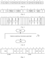
- FIG. 1 A time domain structure of PSSS and SSSS in V2X is shown in FIG. 1 , with a specific distribution of the physical shared broadcast channel (PSBCH), the PSSS, the demodulation reference signal (De-Modulation Reference Signal, DMRS), and the SSSS shown in the figure.
- PSBCH physical shared broadcast channel
- PSSS PSSS
- DMRS De-Modulation Reference Signal
- SSSS SSSS
- Embodiments of this disclosure provides a synchronization signal transmission method and a terminal, to solve a problem that sidelink synchronization signal setting solutions in related technologies cannot satisfy usage requirements, failing to ensure normal sidelink synchronization signal services for users or ensure the reliability and efficiency of communication.
- an embodiment of this disclosure provides a synchronization signal transmission method, applied to a terminal and including:
- an embodiment of this disclosure provides a terminal, including:
- an embodiment of this disclosure provides a terminal, including: a memory, a processor, and a computer program stored in the memory and capable of running on the processor, where when the computer program is executed by the processor, the steps of the foregoing synchronization signal transmission method are implemented.
- an embodiment of this disclosure provides a computer-readable storage medium, where the computer-readable storage medium stores a computer program, and when the computer program is executed by a processor, the steps of the foregoing synchronization signal transmission method are implemented.
- a beneficial effect of the embodiments of this disclosure is to improve a network communication process and ensure reliability of network communication by distributing a PSSS and an SSSS in OFDM symbols occupied by a sidelink synchronization signal block.
- the terms such as “example” or “for example” are used to represent an example, an illustration, or a description. Any embodiment or design scheme described by “example” or “for example” in the embodiments of this disclosure should not be explained as being more preferred or more advantageous than other embodiments or design schemes. To be precise, the terms such as “example” or “for example” are intended to present a related concept in a specific manner.
- the wireless communications system may be a system employing the fifth generation (5th Generation, 5G) mobile communications technologies (hereinafter abbreviated as 5G system).
- 5G system fifth generation mobile communications technologies
- a time domain structure of an SSB below is related to its subcarrier spacing (SubCarrier Spacing, SCS).
- the time domain structure of the SSB is shown in FIG. 2 ; and when the SSB SCS is 120 kHz, the time domain structure of the SSB is shown in FIG. 3 .
- a synchronization raster (Synchronization raster) is defined for 0-100 GHz in NR, and a synchronization raster number is a global synchronization raster number (Global SynChronization raster Number, GSCN).
- Abase station may send an SSB on a synchronization raster, and a user may search for an SSB on the synchronization raster.
- a synchronization raster is not located fixedly at the center of a carrier in which it is located. Therefore, a base station can configure carriers and send an SSB more flexibly.
- a large bandwidth is introduced in NR, and a bandwidth may be up to 400 MHz, or even 1 GHz in a high frequency band.
- An operating sidelink frequency band may overlap with an operating frequency band of NR and/or other services. If a raster of a synchronization signal in a sidelink is too close to or even overlaps with a raster of a synchronization signal of a service with an overlapping operating frequency, a user may be unable to distinguish the synchronization signal of a sidelink service from the synchronization signal of that service, leading to false demodulation of a synchronization signal of that service, and increasing a latency and power consumption.
- the sidelink service refers to a service performed on a sidelink, that is, a communication service performed on the sidelink, such as device-to-device (Device-to-Device, D2D) and vehicle-to-everything (Vehicle-to-Everything, V2X).
- V2X mainly includes vehicle-to-vehicle (Vehicle-to-Vehicle, V2V), vehicle-to-infrastructure (Vehicle-to-Infrastructure, V2I), vehicle-to-network (Vehicle-to-Network, V2N), and vehicle-to-pedestrian (Vehicle-to-Pedestrian, V2P).
- an embodiment of this disclosure provides a synchronization signal transmission method, applied to a terminal and including the following step: Step 401: Transmit or receive a sidelink synchronization signal block.
- the sidelink synchronization signal block includes: a primary sidelink synchronization signal (PSSS) and a secondary sidelink synchronization signal (SSSS), the PSSS and the SSSS being distributed in orthogonal frequency division multiplexing OFDM symbols occupied by the sidelink synchronization signal block.
- PSSS primary sidelink synchronization signal
- SSSS secondary sidelink synchronization signal
- the transmitting or receiving a sidelink synchronization signal block includes both receiving a sidelink synchronization signal block and sending a sidelink synchronization signal block.
- the sidelink synchronization signal block also includes other channels, such as a broadcast channel and/or a service statement channel, and the sidelink synchronization signal block may also include reference signals, such as a DMRS and a sounding reference signal (Sounding reference signal, SRS).
- reference signals such as a DMRS and a sounding reference signal (Sounding reference signal, SRS).
- transmission directions of the sidelink synchronization signal blocks actually transmitted or received on the candidate time domain locations of the two adjacent sidelink synchronization signal blocks may be different, which means that it is possible that both are for sending, or both are for receiving, or one for sending and the other one for receiving.
- the sidelink synchronization signal block is transmitted or received within one time window, and in this case, a transmission time of the sidelink synchronization signal block is called one time window.
- the sidelink synchronization signal block is transmitted or received within a preset time window, and in this case, the sidelink synchronization signal block can only be transmitted or received within the preset time window.
- the preset time window may be a time window pre-configured by a terminal vendor, or may be a time window agreed by a protocol, or may be a time window configured by a base station.
- the PSSS and the SSSS are distributed in the OFDM symbols occupied by the sidelink synchronization signal block according to a preset rule.
- a sidelink synchronization signal block may be transmitted or received based on a slot, or may be transmitted or received based on a sub-slot (or a mini-slot), that is, one slot includes at least candidate time domain locations of one sidelink synchronization signal block.
- the foregoing preset rule may vary when candidate time domain locations of a sidelink synchronization signal block included in one slot are different. Therefore, the following specifically describes the foregoing preset rule from a perspective of a number of candidate time domain locations of a sidelink synchronization signal block included in one slot.
- One slot includes candidate time domain locations of at least two sidelink synchronization signal blocks.
- the preset rule includes at least one of the following:
- SCS subcarrier spacing
- Candidate time domain locations of a sidelink synchronization signal block are unrelated to a subcarrier spacing.
- one slot includes candidate time domain locations of two sidelink synchronization signal blocks.
- the preset rule is: one of the PSSS and the SSSS is located in the second symbol of a sidelink synchronization signal block, and the other of the PSSS and the SSSS is located in the fifth symbol of the sidelink synchronization signal block.
- an OFDM symbol index corresponding to the first symbol of candidate time domain locations of the first sidelink synchronization signal block of two sidelink synchronization signal blocks in one slot is 0, and an OFDM symbol index corresponding to the first symbol of candidate time domain locations of the second sidelink synchronization signal block is 7.
- a PSSS of candidate time domain locations of the first sidelink synchronization signal block is located in a location of an OFDM symbol numbered 1
- a PSSS of candidate time domain locations of the second sidelink synchronization signal block is located in a location of an OFDM symbol numbered 8
- an SSSS of candidate time domain locations of the first sidelink synchronization signal block is located in a location of an OFDM symbol numbered 4
- an SSSS of candidate time domain locations of the second sidelink synchronization signal block is located in a location of an OFDM symbol numbered 11; or when an OFDM symbol number of an SSSS of candidate time domain locations of a sidelink synchronization signal block is less than an OFDM symbol number of a PSSS, an SSSS of candidate time domain locations of the first sidelink synchronization signal block is located in a location of an OFDM symbol numbered 1, an SSSS of candidate time domain locations of the second sidelink
- a PSSS is located in the second symbol of a sidelink synchronization signal block
- an SSSS is located in the fifth symbol of the sidelink synchronization signal block.
- the PSSS of the SL-SSB1 is located in a location of an OFDM symbol numbered 1
- the PSSS of the SL-SSB2 is located in a location of an OFDM symbol numbered 8
- the SSSS of the SL-SSB1 is located in a location of an OFDM symbol numbered 4
- the SSSS of the SL-SSB2 is located in a location of an OFDM symbol numbered 11.
- locations of the PSSS and the SSSS are interchanged, that is, the SSSS is located in the second symbol of a sidelink synchronization signal block, and the PSSS is located in the fifth symbol of the sidelink synchronization signal block.
- a PSSS is located in the second symbol of a sidelink synchronization signal block
- an SSSS is located in the fifth symbol of the sidelink synchronization signal block.
- the PSSS of the SL-SSB1 is located in a location of an OFDM symbol numbered 1
- the PSSS of the SL-SSB2 is located in a location of an OFDM symbol numbered 8
- the SSSS of the SL-SSB1 is located in a location of an OFDM symbol numbered 4
- the SSSS of the SL-SSB2 is located in a location of an OFDM symbol numbered 11.
- locations of the PSSS and the SSSS are interchanged, that is, the SSSS is located in the second symbol of a sidelink synchronization signal block, and the PSSS is located in the fifth symbol of the sidelink synchronization signal block.
- the preset rule is at least one of the following: A21.
- One of the PSSS and the SSSS is located in the second symbol of a sidelink synchronization signal block, and the other of the PSSS and the SSSS is located in the sixth symbol of the sidelink synchronization signal block.
- an OFDM symbol index corresponding to the first symbol of candidate time domain locations of the first sidelink synchronization signal block of two sidelink synchronization signal blocks in one slot is 0, and an OFDM symbol index corresponding to the first symbol of candidate time domain locations of the second sidelink synchronization signal block is 7.
- a PSSS of candidate time domain locations of the first sidelink synchronization signal block is located in a location of an OFDM symbol numbered 1
- a PSSS of candidate time domain locations of the second sidelink synchronization signal block is located in a location of an OFDM symbol numbered 8
- an SSSS of candidate time domain locations of the first sidelink synchronization signal block is located in a location of an OFDM symbol numbered 5
- an SSSS of candidate time domain locations of the second sidelink synchronization signal block is located in a location of an OFDM symbol numbered 12; or when an OFDM symbol number of an SSSS of candidate time domain locations of a sidelink synchronization signal block is less than an OFDM symbol number of a PSSS, an SSSS of candidate time domain locations of the first sidelink synchronization signal block is located in a location of an OFDM symbol numbered 1, an SSSS of candidate time domain locations of the second sidelink
- a PSSS is located in the second symbol of a sidelink synchronization signal block
- an SSSS is located in the sixth symbol of the sidelink synchronization signal block.
- the PSSS of the SL-SSB1 is located in a location of an OFDM symbol numbered 1
- the PSSS of the SL-SSB2 is located in a location of an OFDM symbol numbered 8
- the SSSS of the SL-SSB1 is located in a location of an OFDM symbol numbered 5
- the SSSS of the SL-SSB2 is located in a location of an OFDM symbol numbered 12.
- locations of the PSSS and the SSSS are interchanged, that is, the SSSS is located in the second symbol of a sidelink synchronization signal block, and the PSSS is located in the sixth symbol of the sidelink synchronization signal block.
- One of the PSSS and the SSSS is located in the third symbol of a sidelink synchronization signal block, and the other of the PSSS and the SSSS is located in the sixth symbol of the sidelink synchronization signal block.
- an OFDM symbol index corresponding to the first symbol of candidate time domain locations of the first sidelink synchronization signal block of two sidelink synchronization signal blocks in one slot is 0, and an OFDM symbol index corresponding to the first symbol of candidate time domain locations of the second sidelink synchronization signal block is 7.
- a PSSS of candidate time domain locations of the first sidelink synchronization signal block is located in a location of an OFDM symbol numbered 2
- a PSSS of candidate time domain locations of the second sidelink synchronization signal block is located in a location of an OFDM symbol numbered 9
- an SSSS of candidate time domain locations of the first sidelink synchronization signal block is located in a location of an OFDM symbol numbered 5
- an SSSS of candidate time domain locations of the second sidelink synchronization signal block is located in a location of an OFDM symbol numbered 12; or when an OFDM symbol number of an SSSS of candidate time domain locations of a sidelink synchronization signal block is less than an OFDM symbol number of a PSSS, an SSSS of candidate time domain locations of the first sidelink synchronization signal block is located in a location of an OFDM symbol numbered 2, an SSSS of candidate time domain locations of the second sidelink
- a PSSS is located in the third symbol of a sidelink synchronization signal block
- an SSSS is located in the sixth symbol of the sidelink synchronization signal block.
- the PSSS of the SL-SSB1 is located in a location of an OFDM symbol numbered 2
- the PSSS of the SL-SSB2 is located in a location of an OFDM symbol numbered 9
- the SSSS of the SL-SSB1 is located in a location of an OFDM symbol numbered 5
- the SSSS of the SL-SSB2 is located in a location of an OFDM symbol numbered 12.
- locations of the PSSS and the SSSS are interchanged, that is, the SSSS is located in the third symbol of a sidelink synchronization signal block, and the PSSS is located in the sixth symbol of the sidelink synchronization signal block.
- One of the PSSS and the SSSS is located in the fourth symbol of a sidelink synchronization signal block, and the other of the PSSS and the SSSS is located in the sixth symbol of the sidelink synchronization signal block.
- an OFDM symbol index corresponding to the first symbol of candidate time domain locations of the first sidelink synchronization signal block of two sidelink synchronization signal blocks in one slot is 0, and an OFDM symbol index corresponding to the first symbol of candidate time domain locations of the second sidelink synchronization signal block is 7.
- a PSSS of candidate time domain locations of the first sidelink synchronization signal block is located in a location of an OFDM symbol numbered 3
- a PSSS of candidate time domain locations of the second sidelink synchronization signal block is located in a location of an OFDM symbol numbered 10
- an SSSS of candidate time domain locations of the first sidelink synchronization signal block is located in a location of an OFDM symbol numbered 5
- an SSSS of candidate time domain locations of the second sidelink synchronization signal block is located in a location of an OFDM symbol numbered 12; or when an OFDM symbol number of an SSSS of candidate time domain locations of a sidelink synchronization signal block is less than an OFDM symbol number of a PSSS, an SSSS of candidate time domain locations of the first sidelink synchronization signal block is located in a location of an OFDM symbol numbered 3, an SSSS of candidate time domain locations of the second sidelink
- a PSSS is located in the fourth symbol of a sidelink synchronization signal block
- an SSSS is located in the sixth symbol of the sidelink synchronization signal block.
- the PSSS of the SL-SSB1 is located in a location of an OFDM symbol numbered 3
- the PSSS of the SL-SSB2 is located in a location of an OFDM symbol numbered 10
- the SSSS of the SL-SSB1 is located in a location of an OFDM symbol numbered 5
- the SSSS of the SL-SSB2 is located in a location of an OFDM symbol numbered 12.
- locations of the PSSS and the SSSS are interchanged, that is, the SSSS is located in the fourth symbol of a sidelink synchronization signal block, and the PSSS is located in the sixth symbol of the sidelink synchronization signal block.
- Candidate time domain locations of the sidelink synchronization signal block are related to a subcarrier spacing.
- the subcarrier spacing is a first spacing.
- the preset rule is: one of the PSSS and the SSSS is located in the second symbol of a sidelink synchronization signal block, and the other of the PSSS and the SSSS is located in the fifth symbol of the sidelink synchronization signal block.
- an OFDM symbol index corresponding to the first symbol of candidate time domain locations of the first sidelink synchronization signal block of two sidelink synchronization signal blocks in one slot is 0, and an OFDM symbol index corresponding to the first symbol of candidate time domain locations of the second sidelink synchronization signal block is 7.
- a PSSS of candidate time domain locations of the first sidelink synchronization signal block is located in a location of an OFDM symbol numbered 1
- a PSSS of candidate time domain locations of the second sidelink synchronization signal block is located in a location of an OFDM symbol numbered 8
- an SSSS of candidate time domain locations of the first sidelink synchronization signal block is located in a location of an OFDM symbol numbered 4
- an SSSS of candidate time domain locations of the second sidelink synchronization signal block is located in a location of an OFDM symbol numbered 11; or when an OFDM symbol number of an SSSS of candidate time domain locations of a sidelink synchronization signal block is less than an OFDM symbol number of a PSSS, an SSSS of candidate time domain locations of the first sidelink synchronization signal block is located in a location of an OFDM symbol numbered 1, an SSSS of candidate time domain locations of the second sidelink
- a number of OFDM symbols occupied by a sidelink synchronization signal block is equal to 5, and an OFDM symbol number of a PSSS of candidate time domain locations of a sidelink synchronization signal block is less than an OFDM symbol number of an SSSS, reference may be made to FIG. 5 for distribution; when a number of OFDM symbols occupied by a sidelink synchronization signal block is equal to 6, and an OFDM symbol number of a PSSS of candidate time domain locations of a sidelink synchronization signal block is less than an OFDM symbol number of an SSSS, reference may be made to FIG. 6 for distribution.
- the preset rule is at least one of the following: B121.
- One of the PSSS and the SSSS is located in the second symbol of a sidelink synchronization signal block, and the other of the PSSS and the SSSS is located in the sixth symbol of the sidelink synchronization signal block.
- an OFDM symbol index corresponding to the first symbol of candidate time domain locations of the first sidelink synchronization signal block of two sidelink synchronization signal blocks in one slot is 0, and an OFDM symbol index corresponding to the first symbol of candidate time domain locations of the second sidelink synchronization signal block is 7.
- a PSSS of candidate time domain locations of the first sidelink synchronization signal block is located in a location of an OFDM symbol numbered 1
- a PSSS of candidate time domain locations of the second sidelink synchronization signal block is located in a location of an OFDM symbol numbered 8
- an SSSS of candidate time domain locations of the first sidelink synchronization signal block is located in a location of an OFDM symbol numbered 5
- an SSSS of candidate time domain locations of the second sidelink synchronization signal block is located in a location of an OFDM symbol numbered 12; or when an OFDM symbol number of an SSSS of candidate time domain locations of a sidelink synchronization signal block is less than an OFDM symbol number of a PSSS, an SSSS of candidate time domain locations of the first sidelink synchronization signal block is located in a location of an OFDM symbol numbered 1, an SSSS of candidate time domain locations of the second sidelink
- One of the PSSS and the SSSS is located in the third symbol of a sidelink synchronization signal block, and the other of the PSSS and the SSSS is located in the sixth symbol of the sidelink synchronization signal block.
- an OFDM symbol index corresponding to the first symbol of candidate time domain locations of the first sidelink synchronization signal block of two sidelink synchronization signal blocks in one slot is 0, and an OFDM symbol index corresponding to the first symbol of candidate time domain locations of the second sidelink synchronization signal block is 7.
- a PSSS of candidate time domain locations of the first sidelink synchronization signal block is located in a location of an OFDM symbol numbered 2
- a PSSS of candidate time domain locations of the second sidelink synchronization signal block is located in a location of an OFDM symbol numbered 9
- an SSSS of candidate time domain locations of the first sidelink synchronization signal block is located in a location of an OFDM symbol numbered 5
- an SSSS of candidate time domain locations of the second sidelink synchronization signal block is located in a location of an OFDM symbol numbered 12; or when an OFDM symbol number of an SSSS of candidate time domain locations of a sidelink synchronization signal block is less than an OFDM symbol number of a PSSS, an SSSS of candidate time domain locations of the first sidelink synchronization signal block is located in a location of an OFDM symbol numbered 2, an SSSS of candidate time domain locations of the second sidelink
- One of the PSSS and the SSSS is located in the fourth symbol of a sidelink synchronization signal block, and the other of the PSSS and the SSSS is located in the sixth symbol of the sidelink synchronization signal block.
- an OFDM symbol index corresponding to the first symbol of candidate time domain locations of the first sidelink synchronization signal block of two sidelink synchronization signal blocks in one slot is 0, and an OFDM symbol index corresponding to the first symbol of candidate time domain locations of the second sidelink synchronization signal block is 7.
- a PSSS of candidate time domain locations of the first sidelink synchronization signal block is located in a location of an OFDM symbol numbered 3
- a PSSS of candidate time domain locations of the second sidelink synchronization signal block is located in a location of an OFDM symbol numbered 10
- an SSSS of candidate time domain locations of the first sidelink synchronization signal block is located in a location of an OFDM symbol numbered 5
- an SSSS of candidate time domain locations of the second sidelink synchronization signal block is located in a location of an OFDM symbol numbered 12; or when an OFDM symbol number of an SSSS of candidate time domain locations of a sidelink synchronization signal block is less than an OFDM symbol number of a PSSS, an SSSS of candidate time domain locations of the first sidelink synchronization signal block is located in a location of an OFDM symbol numbered 3, an SSSS of candidate time domain locations of the second sidelink
- the subcarrier spacing is a second spacing.
- the preset rule is at least one of the following: B211.
- One of the PSSS and the SSSS is located in the third symbol of a sidelink synchronization signal block, and the other of the PSSS and the SSSS is located in the sixth symbol of the sidelink synchronization signal block;
- a PSSS is located in the third symbol of a sidelink synchronization signal block
- an SSSS is located in the sixth symbol of the sidelink synchronization signal block.
- the PSSS of the SL-SSB1 is located in a location of an OFDM symbol numbered 2
- the PSSS of the SL-SSB2 is located in a location of an OFDM symbol numbered 8
- the SSSS of the SL-SSB1 is located in a location of an OFDM symbol numbered 5
- the SSSS of the SL-SSB2 is located in a location of an OFDM symbol numbered 11.
- locations of the PSSS and the SSSS are interchanged, that is, the SSSS is located in the third symbol of a sidelink synchronization signal block, and the PSSS is located in the sixth symbol of the sidelink synchronization signal block.
- One of the PSSS and the SSSS is located in the fourth symbol of a sidelink synchronization signal block, and the other of the PSSS and the SSSS is located in the sixth symbol of the sidelink synchronization signal block.
- a PSSS is located in the fourth symbol of a sidelink synchronization signal block
- an SSSS is located in the sixth symbol of the sidelink synchronization signal block.
- the PSSS of the SL-SSB1 is located in a location of an OFDM symbol numbered 3
- the PSSS of the SL-SSB2 is located in a location of an OFDM symbol numbered 9
- the SSSS of the SL-SSB1 is located in a location of an OFDM symbol numbered 5
- the SSSS of the SL-SSB2 is located in a location of an OFDM symbol numbered 11.
- locations of the PSSS and the SSSS are interchanged, that is, the SSSS is located in the fourth symbol of a sidelink synchronization signal block, and the PSSS is located in the sixth symbol of the sidelink synchronization signal block.
- the preset rule is: one of the PSSS and the SSSS is located in the third symbol of a sidelink synchronization signal block, and the other of the PSSS and the SSSS is located in the fifth symbol of the sidelink synchronization signal block.
- an OFDM symbol index corresponding to the first symbol of candidate time domain locations of the first sidelink synchronization signal block of two sidelink synchronization signal blocks in one slot is 0, and an OFDM symbol index corresponding to the first symbol of candidate time domain locations of the second sidelink synchronization signal block is 7.
- a PSSS of candidate time domain locations of the first sidelink synchronization signal block is located in a location of an OFDM symbol numbered 2
- a PSSS of candidate time domain locations of the second sidelink synchronization signal block is located in a location of an OFDM symbol numbered 9
- an SSSS of candidate time domain locations of the first sidelink synchronization signal block is located in a location of an OFDM symbol numbered 4
- an SSSS of candidate time domain locations of the second sidelink synchronization signal block is located in a location of an OFDM symbol numbered 11; or when an OFDM symbol number of an SSSS of candidate time domain locations of a sidelink synchronization signal block is less than an OFDM symbol number of a PSSS, an SSSS of candidate time domain locations of the first sidelink synchronization signal block is located in a location of an OFDM symbol numbered 2, an SSSS of candidate time domain locations of the second sidelink
- a PSSS is located in the third symbol of a sidelink synchronization signal block
- an SSSS is located in the fifth symbol of the sidelink synchronization signal block.
- the PSSS of the SL-SSB1 is located in a location of an OFDM symbol numbered 2
- the PSSS of the SL-SSB2 is located in a location of an OFDM symbol numbered 9
- the SSSS of the SL-SSB1 is located in a location of an OFDM symbol numbered 4
- the SSSS of the SL-SSB2 is located in a location of an OFDM symbol numbered 11.
- locations of the PSSS and the SSSS are interchanged, that is, the SSSS is located in the third symbol of a sidelink synchronization signal block, and the PSSS is located in the fifth symbol of the sidelink synchronization signal block.
- frequencies contained in the foregoing first spacing and second spacing are at least partly different. For example, of 15 kHz, 30 kHz, 60 kHz, 120 kHz, and 240 kHz, some are grouped to the first spacing, and the others are grouped to the second spacing.
- the first spacing includes: 15 kHz and 30 kHz
- the second spacing includes: 60 kHz, 120 kHz, and 240 kHz. It should be noted that the foregoing description is only one grouping of the first spacing and the second spacing, and does not serve as a limitation in practical applications.
- the preset rule includes: one of the PSSS and the SSSS is located in the third symbol of a sidelink synchronization signal block, and the other of the PSSS and the SSSS is located in the fifth symbol of the sidelink synchronization signal block.
- an OFDM symbol index corresponding to the first symbol of candidate time domain locations of the first sidelink synchronization signal block of two sidelink synchronization signal blocks in one slot is 0, and an OFDM symbol index corresponding to the first symbol of candidate time domain locations of the second sidelink synchronization signal block is 7.
- a PSSS of candidate time domain locations of the first sidelink synchronization signal block is located in a location of an OFDM symbol numbered 2
- a PSSS of candidate time domain locations of the second sidelink synchronization signal block is located in a location of an OFDM symbol numbered 9
- an SSSS of candidate time domain locations of the first sidelink synchronization signal block is located in a location of an OFDM symbol numbered 4
- an SSSS of candidate time domain locations of the second sidelink synchronization signal block is located in a location of an OFDM symbol numbered 11; or when an OFDM symbol number of an SSSS of candidate time domain locations of a sidelink synchronization signal block is less than an OFDM symbol number of a PSSS, an SSSS of candidate time domain locations of the first sidelink synchronization signal block is located in a location of an OFDM symbol numbered 2, an SSSS of candidate time domain locations of the second sidelink
- a PSSS is located in the third symbol of a sidelink synchronization signal block
- an SSSS is located in the fifth symbol of the sidelink synchronization signal block.
- the PSSS of the SL-SSB1 is located in a location of an OFDM symbol numbered 2
- the PSSS of the SL-SSB2 is located in a location of an OFDM symbol numbered 9
- the SSSS of the SL-SSB1 is located in a location of an OFDM symbol numbered 4
- the SSSS of the SL-SSB2 is located in a location of an OFDM symbol numbered 11.
- locations of the PSSS and the SSSS are interchanged, that is, the SSSS is located in the third symbol of a sidelink synchronization signal block, and the PSSS is located in the fifth symbol of the sidelink synchronization signal block.
- One slot includes candidate time domain locations of one sidelink synchronization signal block.
- the preset rule includes at least one of the following:
- Candidate time domain locations of a sidelink synchronization signal block are unrelated to a subcarrier spacing.
- the preset rule is at least one of the following: D1.
- One of the PSSS and the SSSS is located in the third and fourth OFDM symbols of one slot, and the other of the PSSS and the SSSS is located in the eleventh and twelfth OFDM symbols of one slot;
- one slot includes candidate time domain locations of at most one sidelink synchronization signal block, where the PSSS is located in the third and fourth OFDM symbols, and the SSSS is located in the eleventh and twelfth OFDM symbols, that is, the PSSS is located in locations of OFDM symbols numbered 2 and 3, and the SSSS is located in locations of OFDM symbols numbered 10 and 11.
- locations of the PSSS and the SSSS are interchanged, that is, the SSSS is located in locations of OFDM symbols numbered 2 and 3, and the PSSS is located in locations of OFDM symbols numbered 10 and 11.
- the sixth and ninth OFDM symbols of one slot are used for transmitting or receiving a demodulation reference signal, that is, locations of OFDM symbols numbered 5 and 8 are used for transmitting or receiving a demodulation reference signal.
- One of the PSSS and the SSSS is located in the second and third OFDM symbols of one slot, and the other of the PSSS and the SSSS is located in the twelfth and thirteenth OFDM symbols of one slot.
- one slot includes candidate time domain locations of at most one sidelink synchronization signal block, where the PSSS is located in the second and third OFDM symbols, and the SSSS is located in the twelfth and thirteenth OFDM symbols, that is, the PSSS is located in locations of OFDM symbols numbered 1 and 2, and the SSSS is located in locations of OFDM symbols numbered 11 and 12.
- locations of the PSSS and the SSSS are interchanged, that is, the SSSS is located in locations of OFDM symbols numbered 1 and 2, and the PSSS is located in locations of OFDM symbols numbered 11 and 12.
- the sixth and ninth OFDM symbols of one slot are used for transmitting or receiving a demodulation reference signal, that is, locations of OFDM symbols numbered 5 and 8 are used for transmitting or receiving a demodulation reference signal.
- One of the PSSS and the SSSS is located in the fifth and seventh OFDM symbols of one slot, and the other of the PSSS and the SSSS is located in the tenth and twelfth OFDM symbols of one slot.
- one slot includes candidate time domain locations of at most one sidelink synchronization signal block, where the PSSS is located in the fifth and seventh OFDM symbols, and the SSSS is located in the tenth and twelfth OFDM symbols, that is, the PSSS is located in locations of OFDM symbols numbered 4 and 6, and the SSSS is located in locations of OFDM symbols numbered 9 and 11.
- locations of the PSSS and the SSSS are interchanged, that is, the SSSS is located in locations of OFDM symbols numbered 4 and 6, and the PSSS is located in locations of OFDM symbols numbered 9 and 11.
- One of the PSSS and the SSSS is located in the second and ninth OFDM symbols of one slot, and the other of the PSSS and the SSSS is located in the fifth and twelfth OFDM symbols of one slot.
- One of the PSSS and the SSSS is located in the second and ninth OFDM symbols of one slot, and the other of the PSSS and the SSSS is located in the sixth and thirteenth OFDM symbols of one slot.
- One of the PSSS and the SSSS is located in the third and tenth OFDM symbols of one slot, and the other of the PSSS and the SSSS is located in the sixth and thirteenth OFDM symbols of one slot.
- One of the PSSS and the SSSS is located in the fourth and eleventh OFDM symbols of one slot, and the other of the PSSS and the SSSS is located in the sixth and thirteenth OFDM symbols of one slot.
- Candidate time domain locations of the sidelink synchronization signal block are related to a subcarrier spacing.
- the subcarrier spacing is a third spacing.
- the preset rule is at least one of the following: E11.
- One of the PSSS and the SSSS is located in the third and sixth OFDM symbols of one slot, and the other of the PSSS and the SSSS is located in the ninth and twelfth OFDM symbols of one slot.
- one slot includes candidate time domain locations of at most one sidelink synchronization signal block, where the PSSS is located in the third and sixth OFDM symbols, and the SSSS is located in the ninth and twelfth OFDM symbols, that is, the PSSS is located in locations of OFDM symbols numbered 2 and 5, and the SSSS is located in locations of OFDM symbols numbered 8 and 11.
- locations of the PSSS and the SSSS are interchanged, that is, the SSSS is located in locations of OFDM symbols numbered 2 and 5, and the PSSS is located in locations of OFDM symbols numbered 8 and 11.
- One of the PSSS and the SSSS is located in the second and ninth OFDM symbols of one slot, and the other of the PSSS and the SSSS is located in the fifth and twelfth OFDM symbols of one slot.
- One of the PSSS and the SSSS is located in the second and ninth OFDM symbols of one slot, and the other of the PSSS and the SSSS is located in the sixth and thirteenth OFDM symbols of one slot.
- One of the PSSS and the SSSS is located in the third and tenth OFDM symbols of one slot, and the other of the PSSS and the SSSS is located in sixth and thirteenth OFDM symbols of one slot.
- One of the PSSS and the SSSS is located in the fourth and eleventh OFDM symbols of one slot, and the other of the PSSS and the SSSS is located in the sixth and thirteenth OFDM symbols of one slot.
- the subcarrier spacing is a fourth spacing.
- the preset rule is at least one of the following: E21.
- One of the PSSS and the SSSS is located in the third and fourth OFDM symbols of one slot, and the other of the PSSS and the SSSS is located in the eleventh and twelfth OFDM symbols of one slot.
- an OFDM symbol number of a PSSS of candidate time domain locations of a sidelink synchronization signal block is less than an OFDM symbol number of an SSSS, reference may be made to FIG. 14 for distribution.
- One of the PSSS and the SSSS is located in the third and ninth OFDM symbols of one slot, and the other of the PSSS and the SSSS is located in the sixth and twelfth OFDM symbols of one slot.
- One of the PSSS and the SSSS is located in the fourth and tenth OFDM symbols of one slot, and the other of the PSSS and the SSSS is located in the sixth and twelfth OFDM symbols of one slot.
- One of the PSSS and the SSSS is located in the third and tenth OFDM symbols of one slot, and the other of the PSSS and the SSSS is located in the fifth and twelfth OFDM symbols of one slot.
- frequencies contained in the foregoing third spacing and fourth spacing are at least partly different. For example, of 15 kHz, 30 kHz, 60 kHz, 120 kHz, and 240 kHz, some are grouped to the third spacing, and the others are grouped to the fourth spacing.
- the third spacing includes: 15 kHz and 30 kHz
- the fourth spacing includes: 60 kHz, 120 kHz, and 240 kHz. It should be noted that the foregoing description is only one grouping of the third spacing and the fourth spacing, and does not serve as a limitation in practical applications.
- the PSSS employs an M-sequence corresponding to a polynomial different from the NR PSS.
- symbol locations marked with a GP in FIG. 5 to FIG. 17 may be left empty and not used for data transmission, or may be used for other purposes, and only one case in which these symbol locations are used as GPs is shown in each of the figures.
- the embodiments of this disclosure can improve network communication process, ensure reliability of network communication, and avoid a problem that a terminal mixes up synchronization signals of different services when a sidelink operating frequency band overlaps with an operating frequency band of another service, ensuring good demodulation performance, such that a terminal can find a sidelink synchronization signal and/or a broadcast channel quickly in different frequency bands, and power consumption is reduced.
- an embodiment of this disclosure further provides a terminal 1800, including:
- the PSSS and the SSSS are distributed in the OFDM symbols occupied by the sidelink synchronization signal block according to a preset rule.
- the preset rule includes at least one of the following:
- the preset rule is: one of the PSSS and the SSSS is located in the second symbol of a sidelink synchronization signal block, and the other of the PSSS and the SSSS is located in the fifth symbol of the sidelink synchronization signal block.
- the preset rule is at least one of the following:
- the preset rule is: one of the PSSS and the SSSS is located in the second symbol of a sidelink synchronization signal block, and the other of the PSSS and the SSSS is located in the fifth symbol of the sidelink synchronization signal block.
- the preset rule is at least one of the following:
- the subcarrier spacing is the second spacing
- one slot includes candidate time domain locations of two sidelink synchronization signal blocks
- a value of x is set to 0, and a value of y is set to 6 or 7.
- the preset rule is at least one of the following:
- the preset rule is: one of the PSSS and the SSSS is located in the third symbol of a sidelink synchronization signal block, and the other of the PSSS and the SSSS is located in the fifth symbol of the sidelink synchronization signal block.
- the preset rule includes: one of the PSSS and the SSSS is located in the third symbol of a sidelink synchronization signal block, and the other of the PSSS and the SSSS is located in the fifth symbol of the sidelink synchronization signal block.
- the preset rule includes at least one of the following:
- the preset rule is: one of the PSSS and the SSSS is located in the third and fourth OFDM symbols of one slot, and the other of the PSSS and the SSSS is located in the eleventh and twelfth OFDM symbols of one slot; or when one of the PSSS and the SSSS is located in the second and third OFDM symbols of one slot, and the other of the PSSS and the SSSS is located in the twelfth and thirteenth OFDM symbols of one slot, the sixth and ninth OFDM symbols of one slot is used for transmitting or receiving a demodulation reference signal.
- the preset rule is at least one of the following:
- the preset rule is at least one of the following:
- the M-sequence includes:
- transmission directions of the sidelink synchronization signal blocks on the candidate time domain locations of the at least two sidelink synchronization signal blocks are the same.
- the sidelink synchronization signal block is transmitted or received within one time window.
- the sidelink synchronization signal block is transmitted or received within a preset time window.
- the terminal embodiment is a terminal corresponding to the foregoing synchronization signal transmission method applied to a terminal side, all implementations of the foregoing embodiments are applicable to the terminal embodiment, and a same technical effect can be achieved.
- FIG. 19 is a schematic diagram of a hardware structure of a terminal for implementing the embodiments of this disclosure.
- the terminal 190 includes but is not limited to components such as a radio frequency unit 1910, a network module 1920, an audio output unit 1930, an input unit 1940, a sensor 1950, a display unit 1960, a user input unit 1970, an interface unit 1980, a memory 1990, a processor 1911, and a power supply 1912.
- a radio frequency unit 1910 such as a radio frequency unit 1910, a network module 1920, an audio output unit 1930, an input unit 1940, a sensor 1950, a display unit 1960, a user input unit 1970, an interface unit 1980, a memory 1990, a processor 1911, and a power supply 1912.
- the terminal may include more or fewer components than those shown in the figure, or some components are combined, or component arrangements are different.
- the terminal includes but is not limited to a mobile phone, a tablet computer, a notebook computer, a palmtop computer, an in-vehicle terminal, a wearable device, a pedometer, or the like.
- the radio frequency unit 1910 is configured to transmit or receive a sidelink synchronization signal block; where the sidelink synchronization signal block includes: a primary sidelink synchronization signal PSSS and a secondary sidelink synchronization signal SSSS, the PSSS and the SSSS being distributed in orthogonal frequency division multiplexing OFDM symbols occupied by the sidelink synchronization signal block.
- the sidelink synchronization signal block includes: a primary sidelink synchronization signal PSSS and a secondary sidelink synchronization signal SSSS, the PSSS and the SSSS being distributed in orthogonal frequency division multiplexing OFDM symbols occupied by the sidelink synchronization signal block.
- the terminal according to this embodiment of this disclosure can improve network communication process and ensure reliability of network communication by distributing a PSSS and an SSSS in OFDM symbols occupied by a sidelink synchronization signal block.
- the radio frequency unit 1910 may be configured to receive and send signals in an information reception or transmission or call process. Specifically, after receiving downlink data from the network device, the radio frequency unit 1910 sends the downlink data to the processor 1911 for processing, and in addition, sends uplink data to the network device.
- the radio frequency unit 1910 includes but is not limited to an antenna, at least one amplifier, a transceiver, a coupler, a low noise amplifier, a duplexer, and the like.
- the radio frequency unit 1910 may further communicate with a network and another device through a wireless communications system.
- the terminal provides wireless broadband internet access for a user by using the network module 1920, for example, helps the user send and receive e-mails, browse web pages, and access streaming media.
- the audio output unit 1930 may convert audio data received by the radio frequency unit 1910 or the network module 1920 or stored in the memory 1990 into an audio signal and output the audio signal as a sound.
- the audio output unit 1930 may further provide audio output (for example, a call signal reception tone or a message reception tone) that is related to a specific function performed by the terminal 190.
- the audio output unit 1930 includes a speaker, a buzzer, a telephone receiver, and the like.
- the input unit 1940 is configured to receive an audio or video signal.
- the input unit 1940 may include a graphics processing unit (Graphics Processing Unit, GPU) 1941 and a microphone 1942, and the graphics processing unit 1941 processes image data of a still picture or a video obtained by an image capture apparatus (for example, a camera) in an image capture mode or a video capture mode.
- a processed image frame may be displayed on the display unit 1960.
- the image frame processed by the graphics processing unit 1941 may be stored in the memory 1990 (or another storage medium) or sent by the radio frequency unit 1910 or the network module 1920.
- the microphone 1942 can receive a sound and can process the sound into audio data.
- the processed audio data may be converted, in a telephone call mode, into a format that can be sent to a mobile communications network device through the radio frequency unit 1910, for outputting.
- the terminal 190 further includes at least one sensor 1950, for example, an optical sensor, a motion sensor, and another sensor.
- the optical sensor includes an ambient light sensor and a proximity sensor.
- the ambient light sensor may adjust brightness of a display panel 1961 based on intensity of ambient light.
- the proximity sensor may disable the display panel 1961 and/or backlight.
- an accelerometer sensor may detect for a value of an acceleration in various directions (there are usually three axes), may detect for a value and a direction of gravity when the terminal is static, and may be configured to recognize a posture of the terminal (for example, landscape/portrait mode switching, a related game, or magnetometer posture calibration), provide a function related to vibration recognition (for example, a pedometer or a keystroke), or the like.
- the sensor 1950 may further include a fingerprint sensor, a pressure sensor, an iris sensor, a molecular sensor, a gyroscope, a barometer, a hygrometer, a thermometer, or an infrared sensor. Details are not described herein.
- the display unit 1960 is configured to display information input by the user or information provided for the user.
- the display unit 1960 may include a display panel 1961, and the display panel 1961 may be configured in the form of a liquid crystal display (Liquid Crystal Display, LCD), an organic light-emitting diode (Organic Light-Emitting Diode, OLED), or the like.
- LCD Liquid Crystal Display
- OLED Organic Light-Emitting Diode
- the user input unit 1970 may be configured to receive input digit or character information, and generate a key signal input related to a user setting and function control of the terminal.
- the user input unit 1970 includes a touch panel 1971 and other input devices 1972.
- the touch panel 1971 also referred to as a touchscreen, may capture a touch operation performed by a user on or near the touch panel (for example, an operation performed by the user on the touch panel 1971 or near the touch panel 1971 by using any appropriate object or accessory such as a finger or a stylus).
- the touch panel 1971 may include two parts: a touch detection apparatus and a touch controller.
- the touch detection apparatus detects a touch direction of the user, detects a signal carried by a touch operation, and transmits the signal to the touch controller.
- the touch controller receives touch information from the touch detection apparatus, converts the touch information to point coordinates, and sends the point coordinates to the processor 1911, and receives and executes a command sent by the processor 1911.
- the touch panel 1971 may be implemented in a plurality of forms, for example, as a resistive, capacitive, infrared, or surface acoustic wave touch panel.
- the user input unit 1970 may further include other input devices 1972 in addition to the touch panel 1971.
- the other input devices 1972 may include but are not limited to a physical keyboard, a function key (such as a volume control key or a power on/off key), a trackball, a mouse, a joystick, and the like. Details are not described herein.
- the touch panel 1971 may cover the display panel 1961.
- the touch panel 1971 transmits the touch operation to the processor 1911 to determine a type of a touch event.
- the processor 1911 provides a corresponding visual output on the display panel 1961 based on the type of the touch event.
- the touch panel 1971 and the display panel 1961 serve as two independent components to implement input and output functions of the terminal.
- the touch panel 1971 and the display panel 1961 may be integrated to implement the input and output functions of the terminal. This is not specifically limited herein.
- the interface unit 1980 is an interface for connecting an external apparatus to the terminal 190.
- the external apparatus may include a wired or wireless headphone port, an external power (or battery charger) port, a wired or wireless data port, a memory card port, a port for connecting an apparatus having an identification module, an audio input/output (I/O) port, a video I/O port, an earphone port, and the like.
- the interface unit 1980 may be configured to receive input (for example, data information and electric power) from the external apparatus, and transmit the received input to one or more elements in the terminal 190; or may be configured to transmit data between the terminal 190 and the external apparatus.
- the memory 1990 may be configured to store a software program and various data.
- the memory 1990 may mainly include a program storage area and a data storage area.
- the program storage area may store an operating system, an application program required for at least one function (such as a sound play function and an image play function), and the like.
- the data storage area may store data (such as audio data and a phone book) created based on use of a mobile phone, and the like.
- the memory 1990 may include a high-speed random access memory, or may include a non-volatile memory, for example, at least one magnetic disk storage device, a flash memory device, or other volatile solid-state storage devices.
- the processor 1911 is a control center of the terminal, connects various parts of the entire terminal by using various interfaces and lines, and executes various functions and data processing of the terminal by running or executing a software program and/or a module stored in the memory 1990 and invoking data stored in the memory 1990, so as to perform overall monitoring on the terminal.
- the processor 1911 may include one or more processing units.
- the processor 1911 may integrate an application processor and a modem processor.
- the application processor mainly processes an operating system, a user interface, an application program, and the like.
- the modem processor mainly processes wireless communication. It may be understood that the modem processor may alternatively not be integrated into the processor 1911.
- the terminal 190 may further include the power supply 1912 (for example, a battery) that supplies power to each component.
- the power supply 1912 may be logically connected to the processor 1911 by using a power management system, so as to implement functions such as charging management, discharging management, and power consumption management by using the power management system.
- terminal 190 may include some functional modules that are not shown. Details are not described herein.
- an embodiment of this disclosure further provides a terminal, including a processor 1911, a memory 1990, and a computer program stored in the memory 1990 and capable of running on the processor 1911.
- a terminal including a processor 1911, a memory 1990, and a computer program stored in the memory 1990 and capable of running on the processor 1911.
- the computer program is executed by the processor 1911, the processes of the embodiments of the synchronization signal transmission method applied to the terminal side are implemented, and a same technical effect can be achieved. To avoid repetition, details are not described herein again.
- An embodiment of this disclosure further provides a computer-readable storage medium, where the computer-readable storage medium stores a computer program.
- the computer program is executed by a processor, the processes of the embodiments of the synchronization signal transmission method applied to the terminal side are implemented, and a same technical effect can be achieved. To avoid repetition, details are not described herein again.
- the computer-readable storage medium is a read-only memory (Read-Only Memory, ROM), a random access memory (Random Access Memory, RAM), a magnetic disk, or an optical disk.
- the network device may be a base transceiver station (Base Transceiver Station, BTS) in a global system for mobile communications (Global System for Mobile Communications, GSM) or code division multiple access (Code Division Multiple Access, CDMA), or may be a NodeB (NodeB, NB) in wideband code division multiple access (Wideband Code Division Multiple Access, WCDMA), or may be an evolved NodeB (Evolved NodeB, eNB or eNodeB), a relay station, or an access point in LTE, or may be a base station in a future 8G network, or the like, which is not limited herein.
- BTS Base Transceiver Station
- GSM Global System for Mobile Communications
- CDMA Code Division Multiple Access
- NodeB NodeB
- WCDMA Wideband Code Division Multiple Access
- Evolved NodeB, eNB or eNodeB evolved NodeB
- a relay station or an access point in LTE, or may be a base station in a future 8
- the method in the foregoing embodiments may be implemented by software on a necessary universal hardware platform or by hardware only. In most cases, the former is a more preferred implementation.
- the technical solutions of this disclosure essentially or a part thereof that contributes to related technologies may be embodied in a form of a software product.
- the computer software product is stored in a storage medium (for example, a ROM/RAM, a magnetic disk, or an optical disc), and includes several instructions for instructing a terminal (which may be a mobile phone, a computer, a server, an air conditioner, a network device, or the like) to perform the methods described in the embodiments of this disclosure.
Landscapes
- Engineering & Computer Science (AREA)
- Signal Processing (AREA)
- Computer Networks & Wireless Communication (AREA)
- Mobile Radio Communication Systems (AREA)
- Synchronisation In Digital Transmission Systems (AREA)
Applications Claiming Priority (2)
| Application Number | Priority Date | Filing Date | Title |
|---|---|---|---|
| CN201810856303.1A CN110768771B (zh) | 2018-07-27 | 2018-07-27 | 同步信号传输方法及终端 |
| PCT/CN2019/096338 WO2020020031A1 (zh) | 2018-07-27 | 2019-07-17 | 同步信号传输方法及终端 |
Publications (3)
| Publication Number | Publication Date |
|---|---|
| EP3832934A1 true EP3832934A1 (de) | 2021-06-09 |
| EP3832934A4 EP3832934A4 (de) | 2021-09-22 |
| EP3832934B1 EP3832934B1 (de) | 2025-10-15 |
Family
ID=69180283
Family Applications (1)
| Application Number | Title | Priority Date | Filing Date |
|---|---|---|---|
| EP19840206.7A Active EP3832934B1 (de) | 2018-07-27 | 2019-07-17 | Synchronisationssignalübertragungsverfahren und endgerät |
Country Status (9)
| Country | Link |
|---|---|
| US (1) | US12192921B2 (de) |
| EP (1) | EP3832934B1 (de) |
| JP (1) | JP7179178B2 (de) |
| KR (1) | KR102853202B1 (de) |
| CN (1) | CN110768771B (de) |
| ES (1) | ES3050091T3 (de) |
| MY (1) | MY210085A (de) |
| SG (1) | SG11202100904YA (de) |
| WO (1) | WO2020020031A1 (de) |
Families Citing this family (9)
| Publication number | Priority date | Publication date | Assignee | Title |
|---|---|---|---|---|
| KR102637452B1 (ko) * | 2018-08-17 | 2024-02-16 | 주식회사 아이티엘 | Nr v2x 시스템을 위한 동기화 신호 송수신 방법 및 그 장치 |
| EP3876615A4 (de) * | 2018-11-02 | 2022-02-23 | Fujitsu Limited | Verfahren und vorrichtung zum senden und empfangen von sidelink-informationen |
| KR102834753B1 (ko) * | 2019-01-10 | 2025-07-16 | 삼성전자 주식회사 | 무선 통신 시스템에서 동기 신호를 전송하기 위한 방법 및 장치 |
| WO2020145268A1 (en) * | 2019-01-10 | 2020-07-16 | Sharp Kabushiki Kaisha | Synchronization for v2x communication |
| CN111526578B (zh) * | 2019-02-03 | 2021-06-22 | 华为技术有限公司 | 一种传输同步信号的方法及终端设备 |
| CN112188446B (zh) * | 2019-07-05 | 2022-04-08 | 大唐移动通信设备有限公司 | 一种同步信号发送方法、终端及装置、存储介质 |
| CN119094637A (zh) * | 2020-01-21 | 2024-12-06 | 中兴通讯股份有限公司 | 一种无线通信方法、终端、网络节点及非暂时性计算机可读介质 |
| WO2021248300A1 (en) * | 2020-06-09 | 2021-12-16 | Qualcomm Incorporated | Sidelink synchronization signal block transmissions in a shared spectrum |
| CN115915349A (zh) * | 2021-08-24 | 2023-04-04 | 展讯通信(上海)有限公司 | 一种通信方法及相关装置 |
Family Cites Families (19)
| Publication number | Priority date | Publication date | Assignee | Title |
|---|---|---|---|---|
| WO2015111908A1 (ko) * | 2014-01-26 | 2015-07-30 | 엘지전자(주) | 단말 간 통신을 지원하는 무선 통신 시스템에서 동기 신호 및 동기 채널 전송 방법 및 이를 위한 장치 |
| KR102396041B1 (ko) * | 2014-05-09 | 2022-05-10 | 엘지전자 주식회사 | 무선 통신 시스템에서 단말 간 직접 통신을 위한 동기화 신호를 전송하는 방법 및 이를 위한 장치 |
| WO2016010390A1 (ko) * | 2014-07-18 | 2016-01-21 | 삼성전자 주식회사 | 무선 통신 시스템에서 단말 간 통신을 위한 동기화 방법 및 장치 |
| KR101901949B1 (ko) * | 2014-08-26 | 2018-09-28 | 엘지전자 주식회사 | 무선 통신 시스템에서 동기 신호를 송수신하는 방법 및 이를 수행하는 장치 |
| EP3190732B1 (de) * | 2014-09-02 | 2019-05-15 | LG Electronics Inc. | Verfahren und vorrichtung zur übertragung eines synchronisierungssignals über ein vorrichtung-zu-vorrichtung-endgerät in einem drahtloskommunikationssystem |
| CN105659675B (zh) | 2014-09-23 | 2019-05-28 | 华为技术有限公司 | 发射器,接收器,和用于发送/接收同步信号的方法 |
| CN107005799B (zh) * | 2014-12-08 | 2020-06-30 | Lg 电子株式会社 | 无线通信系统中执行设备对设备通信的方法和执行该方法的设备 |
| US9888450B2 (en) * | 2014-12-16 | 2018-02-06 | Lg Electronics Inc. | Method and apparatus for detecting synchronization signal in wireless communication system |
| US10320600B2 (en) | 2015-01-02 | 2019-06-11 | Lg Electronics Inc. | Method for D2D signal transmission in wireless communication system, and terminal using same |
| WO2016159716A1 (ko) * | 2015-04-01 | 2016-10-06 | 엘지전자 주식회사 | 무선 통신 시스템에서 레인징 관련 동작 수행 방법 |
| CN108141340B (zh) * | 2015-10-01 | 2020-11-24 | Lg 电子株式会社 | 在d2d通信中发送参考信号的方法和终端 |
| US20180270776A1 (en) | 2015-10-02 | 2018-09-20 | Ntt Docomo, Inc. | User apparatus and synchronization method |
| US9974039B2 (en) * | 2015-12-21 | 2018-05-15 | Intel IP Corporation | User equipment and method for measurement of side-link reference signal received power (S-RSRP) |
| JP6816857B2 (ja) * | 2016-01-20 | 2021-01-20 | ホアウェイ・テクノロジーズ・カンパニー・リミテッド | 同期情報送信方法および装置 |
| CN107734557B (zh) * | 2016-08-11 | 2023-04-21 | 北京三星通信技术研究有限公司 | 一种v2x通信中避免对蜂窝通信干扰的方法和设备 |
| US10805893B2 (en) * | 2016-08-19 | 2020-10-13 | Samsung Electronics Co., Ltd | System and method for providing universal synchronization signals for new radio |
| US10687252B2 (en) * | 2016-09-28 | 2020-06-16 | Qualcomm Incorporated | Bandwidth group (BWG) for enhanced channel and interference mitigation in 5G new radio |
| CN107018564B (zh) * | 2017-06-01 | 2019-09-10 | 重庆邮电大学 | 一种丢失覆盖场景中的d2d终端发送功率控制方法 |
| US10834708B2 (en) * | 2018-07-06 | 2020-11-10 | Samsung Electronics Co., Ltd. | Method and apparatus for NR sidelink SS/PBCH block |
-
2018
- 2018-07-27 CN CN201810856303.1A patent/CN110768771B/zh active Active
-
2019
- 2019-07-17 MY MYPI2021000386A patent/MY210085A/en unknown
- 2019-07-17 EP EP19840206.7A patent/EP3832934B1/de active Active
- 2019-07-17 JP JP2021527268A patent/JP7179178B2/ja active Active
- 2019-07-17 KR KR1020217005204A patent/KR102853202B1/ko active Active
- 2019-07-17 ES ES19840206T patent/ES3050091T3/es active Active
- 2019-07-17 WO PCT/CN2019/096338 patent/WO2020020031A1/zh not_active Ceased
- 2019-07-17 SG SG11202100904YA patent/SG11202100904YA/en unknown
-
2021
- 2021-01-27 US US17/160,248 patent/US12192921B2/en active Active
Also Published As
| Publication number | Publication date |
|---|---|
| US12192921B2 (en) | 2025-01-07 |
| CN110768771B (zh) | 2021-07-27 |
| WO2020020031A1 (zh) | 2020-01-30 |
| ES3050091T3 (en) | 2025-12-19 |
| CN110768771A (zh) | 2020-02-07 |
| SG11202100904YA (en) | 2021-02-25 |
| EP3832934A4 (de) | 2021-09-22 |
| EP3832934B1 (de) | 2025-10-15 |
| MY210085A (en) | 2025-08-26 |
| JP2021532701A (ja) | 2021-11-25 |
| JP7179178B2 (ja) | 2022-11-28 |
| KR102853202B1 (ko) | 2025-08-29 |
| KR20210024660A (ko) | 2021-03-05 |
| US20210153146A1 (en) | 2021-05-20 |
Similar Documents
| Publication | Publication Date | Title |
|---|---|---|
| US12192921B2 (en) | Synchronization signal transmission method and terminal | |
| CN111817831B (zh) | 一种传输方法和通信设备 | |
| AU2019316839B2 (en) | Determination method, terminal and network device | |
| EP3986032A1 (de) | Pdcch-überwachungsverfahren und endgerät | |
| SG11202110849RA (en) | Method for determining channel resource, channel detection method, and terminal | |
| EP3952180A1 (de) | Suchraumkonfigurationsverfahren und -gerät sowie kommunikationsgerät | |
| AU2019413517B2 (en) | Information receiving method, information sending method, terminal, and network side device | |
| EP3952583A1 (de) | Abbildungsverfahren, endgerätevorrichtung und netzwerkseitige vorrichtung | |
| CN113225816B (zh) | 物理上行控制信道传输方法、装置、设备及介质 | |
| JP2022528236A (ja) | Ssb伝送指示方法、装置、端末、機器及び媒体 | |
| US12476753B2 (en) | Information transmission method, network side device and terminal device | |
| CN111836266B (zh) | Srs的发送方法、配置方法、终端及网络侧设备 | |
| WO2020199933A1 (zh) | 旁链路同步信号块传输位置确定方法、设备及介质 | |
| CN111836307A (zh) | 映射类型的确定方法及终端 | |
| EP4102914A1 (de) | Verfahren und endgerät zur bestimmung eines systembetriebsmodus | |
| EP3996450A1 (de) | Übertragungsverfahren, interferenzverarbeitungsverfahren, endgerät und netzwerkseitige vorrichtung | |
| CN112769528B (zh) | 上行探测导频发送方法、接收方法及相关设备 | |
| EP4013160A1 (de) | Verfahren, vorrichtung und system zur konfiguration von ressourcen | |
| HK40064729A (en) | Transmission method, interference processing method, terminal, and network-side device | |
| HK40062013A (en) | Channel resource determination method, channel detection method and terminal | |
| HK40063757A (en) | Pdcch monitoring method and terminal | |
| HK40044888A (en) | Determination method, terminal and network device | |
| WO2020029797A1 (zh) | 确定方法、终端及网络设备 | |
| CN109600207A (zh) | 一种上行控制信道配置的传输方法和相关设备 |
Legal Events
| Date | Code | Title | Description |
|---|---|---|---|
| STAA | Information on the status of an ep patent application or granted ep patent |
Free format text: STATUS: THE INTERNATIONAL PUBLICATION HAS BEEN MADE |
|
| PUAI | Public reference made under article 153(3) epc to a published international application that has entered the european phase |
Free format text: ORIGINAL CODE: 0009012 |
|
| STAA | Information on the status of an ep patent application or granted ep patent |
Free format text: STATUS: REQUEST FOR EXAMINATION WAS MADE |
|
| 17P | Request for examination filed |
Effective date: 20210226 |
|
| AK | Designated contracting states |
Kind code of ref document: A1 Designated state(s): AL AT BE BG CH CY CZ DE DK EE ES FI FR GB GR HR HU IE IS IT LI LT LU LV MC MK MT NL NO PL PT RO RS SE SI SK SM TR |
|
| A4 | Supplementary search report drawn up and despatched |
Effective date: 20210825 |
|
| RIC1 | Information provided on ipc code assigned before grant |
Ipc: H04L 5/00 20060101AFI20210819BHEP |
|
| DAV | Request for validation of the european patent (deleted) | ||
| DAX | Request for extension of the european patent (deleted) | ||
| STAA | Information on the status of an ep patent application or granted ep patent |
Free format text: STATUS: EXAMINATION IS IN PROGRESS |
|
| 17Q | First examination report despatched |
Effective date: 20230331 |
|
| GRAP | Despatch of communication of intention to grant a patent |
Free format text: ORIGINAL CODE: EPIDOSNIGR1 |
|
| STAA | Information on the status of an ep patent application or granted ep patent |
Free format text: STATUS: GRANT OF PATENT IS INTENDED |
|
| INTG | Intention to grant announced |
Effective date: 20250616 |
|
| GRAS | Grant fee paid |
Free format text: ORIGINAL CODE: EPIDOSNIGR3 |
|
| GRAA | (expected) grant |
Free format text: ORIGINAL CODE: 0009210 |
|
| STAA | Information on the status of an ep patent application or granted ep patent |
Free format text: STATUS: THE PATENT HAS BEEN GRANTED |
|
| AK | Designated contracting states |
Kind code of ref document: B1 Designated state(s): AL AT BE BG CH CY CZ DE DK EE ES FI FR GB GR HR HU IE IS IT LI LT LU LV MC MK MT NL NO PL PT RO RS SE SI SK SM TR |
|
| REG | Reference to a national code |
Ref country code: GB Ref legal event code: FG4D Ref country code: CH Ref legal event code: F10 Free format text: ST27 STATUS EVENT CODE: U-0-0-F10-F00 (AS PROVIDED BY THE NATIONAL OFFICE) Effective date: 20251015 |
|
| REG | Reference to a national code |
Ref country code: IE Ref legal event code: FG4D |
|
| REG | Reference to a national code |
Ref country code: DE Ref legal event code: R096 Ref document number: 602019076979 Country of ref document: DE |
|
| REG | Reference to a national code |
Ref country code: NL Ref legal event code: FP |
|
| REG | Reference to a national code |
Ref country code: ES Ref legal event code: FG2A Ref document number: 3050091 Country of ref document: ES Kind code of ref document: T3 Effective date: 20251219 |
|
| REG | Reference to a national code |
Ref country code: AT Ref legal event code: MK05 Ref document number: 1848005 Country of ref document: AT Kind code of ref document: T Effective date: 20251015 |
|
| REG | Reference to a national code |
Ref country code: LT Ref legal event code: MG9D |
|
| PG25 | Lapsed in a contracting state [announced via postgrant information from national office to epo] |
Ref country code: NO Free format text: LAPSE BECAUSE OF FAILURE TO SUBMIT A TRANSLATION OF THE DESCRIPTION OR TO PAY THE FEE WITHIN THE PRESCRIBED TIME-LIMIT Effective date: 20260115 |
|
| PG25 | Lapsed in a contracting state [announced via postgrant information from national office to epo] |
Ref country code: HR Free format text: LAPSE BECAUSE OF FAILURE TO SUBMIT A TRANSLATION OF THE DESCRIPTION OR TO PAY THE FEE WITHIN THE PRESCRIBED TIME-LIMIT Effective date: 20251015 Ref country code: AT Free format text: LAPSE BECAUSE OF FAILURE TO SUBMIT A TRANSLATION OF THE DESCRIPTION OR TO PAY THE FEE WITHIN THE PRESCRIBED TIME-LIMIT Effective date: 20251015 Ref country code: FI Free format text: LAPSE BECAUSE OF FAILURE TO SUBMIT A TRANSLATION OF THE DESCRIPTION OR TO PAY THE FEE WITHIN THE PRESCRIBED TIME-LIMIT Effective date: 20251015 |
|
| PG25 | Lapsed in a contracting state [announced via postgrant information from national office to epo] |
Ref country code: RS Free format text: LAPSE BECAUSE OF FAILURE TO SUBMIT A TRANSLATION OF THE DESCRIPTION OR TO PAY THE FEE WITHIN THE PRESCRIBED TIME-LIMIT Effective date: 20260115 |
|
| PG25 | Lapsed in a contracting state [announced via postgrant information from national office to epo] |
Ref country code: IS Free format text: LAPSE BECAUSE OF FAILURE TO SUBMIT A TRANSLATION OF THE DESCRIPTION OR TO PAY THE FEE WITHIN THE PRESCRIBED TIME-LIMIT Effective date: 20260215 |
|
| PG25 | Lapsed in a contracting state [announced via postgrant information from national office to epo] |
Ref country code: PT Free format text: LAPSE BECAUSE OF FAILURE TO SUBMIT A TRANSLATION OF THE DESCRIPTION OR TO PAY THE FEE WITHIN THE PRESCRIBED TIME-LIMIT Effective date: 20260216 |
|
| PG25 | Lapsed in a contracting state [announced via postgrant information from national office to epo] |
Ref country code: PL Free format text: LAPSE BECAUSE OF FAILURE TO SUBMIT A TRANSLATION OF THE DESCRIPTION OR TO PAY THE FEE WITHIN THE PRESCRIBED TIME-LIMIT Effective date: 20251015 |
|
| PG25 | Lapsed in a contracting state [announced via postgrant information from national office to epo] |
Ref country code: LV Free format text: LAPSE BECAUSE OF FAILURE TO SUBMIT A TRANSLATION OF THE DESCRIPTION OR TO PAY THE FEE WITHIN THE PRESCRIBED TIME-LIMIT Effective date: 20251015 |