EP3833227B1 - Leicht einsetzbarer becherhalter - Google Patents
Leicht einsetzbarer becherhalter Download PDFInfo
- Publication number
- EP3833227B1 EP3833227B1 EP19752486.1A EP19752486A EP3833227B1 EP 3833227 B1 EP3833227 B1 EP 3833227B1 EP 19752486 A EP19752486 A EP 19752486A EP 3833227 B1 EP3833227 B1 EP 3833227B1
- Authority
- EP
- European Patent Office
- Prior art keywords
- connection
- machine
- receiver
- beverage
- connecting part
- Prior art date
- Legal status (The legal status is an assumption and is not a legal conclusion. Google has not performed a legal analysis and makes no representation as to the accuracy of the status listed.)
- Active
Links
Images
Classifications
-
- A—HUMAN NECESSITIES
- A47—FURNITURE; DOMESTIC ARTICLES OR APPLIANCES; COFFEE MILLS; SPICE MILLS; SUCTION CLEANERS IN GENERAL
- A47J—KITCHEN EQUIPMENT; COFFEE MILLS; SPICE MILLS; APPARATUS FOR MAKING BEVERAGES
- A47J31/00—Apparatus for making beverages
- A47J31/44—Parts or details or accessories of beverage-making apparatus
- A47J31/4403—Constructional details
- A47J31/441—Warming devices or supports for beverage containers
- A47J31/4425—Supports for beverage containers when filled or while being filled
- A47J31/4428—Supports for beverage containers when filled or while being filled with a drip-tray underneath
-
- A—HUMAN NECESSITIES
- A47—FURNITURE; DOMESTIC ARTICLES OR APPLIANCES; COFFEE MILLS; SPICE MILLS; SUCTION CLEANERS IN GENERAL
- A47J—KITCHEN EQUIPMENT; COFFEE MILLS; SPICE MILLS; APPARATUS FOR MAKING BEVERAGES
- A47J31/00—Apparatus for making beverages
- A47J31/40—Beverage-making apparatus with dispensing means for adding a measured quantity of ingredients, e.g. coffee, water, sugar, cocoa, milk, tea
- A47J31/407—Beverage-making apparatus with dispensing means for adding a measured quantity of ingredients, e.g. coffee, water, sugar, cocoa, milk, tea with ingredient-containing cartridges; Cartridge-perforating means
-
- A—HUMAN NECESSITIES
- A47—FURNITURE; DOMESTIC ARTICLES OR APPLIANCES; COFFEE MILLS; SPICE MILLS; SUCTION CLEANERS IN GENERAL
- A47J—KITCHEN EQUIPMENT; COFFEE MILLS; SPICE MILLS; APPARATUS FOR MAKING BEVERAGES
- A47J31/00—Apparatus for making beverages
- A47J31/44—Parts or details or accessories of beverage-making apparatus
- A47J31/4403—Constructional details
-
- A—HUMAN NECESSITIES
- A47—FURNITURE; DOMESTIC ARTICLES OR APPLIANCES; COFFEE MILLS; SPICE MILLS; SUCTION CLEANERS IN GENERAL
- A47J—KITCHEN EQUIPMENT; COFFEE MILLS; SPICE MILLS; APPARATUS FOR MAKING BEVERAGES
- A47J31/00—Apparatus for making beverages
- A47J31/44—Parts or details or accessories of beverage-making apparatus
- A47J31/4482—Details allowing to adapt the beverage-making apparatus to the size of the brewing vessel or the beverage container, e.g. with adjustable support for the beverage container or adjustable hot water outlet
-
- A—HUMAN NECESSITIES
- A47—FURNITURE; DOMESTIC ARTICLES OR APPLIANCES; COFFEE MILLS; SPICE MILLS; SUCTION CLEANERS IN GENERAL
- A47J—KITCHEN EQUIPMENT; COFFEE MILLS; SPICE MILLS; APPARATUS FOR MAKING BEVERAGES
- A47J31/00—Apparatus for making beverages
- A47J31/44—Parts or details or accessories of beverage-making apparatus
- A47J31/46—Dispensing spouts, pumps, drain valves or like liquid transporting devices
Definitions
- the field of the invention pertains to beverage dispensing machines having a beverage outlet, a service unit and a movable cup support.
- the beverage preparation machine uses receptacles of an ingredient of the beverage to be prepared, in particular to machine is arranged to prepare the beverage by circulation of a liquid into the ingredient receptacle and centrifugation thereof, typically to brew the beverage in the ingredient receptacle and extract the beverage therefrom.
- a "beverage” is meant to include any human-consumable liquid substance, such as tea, coffee, hot or cold chocolate, milk, soup, baby food, etc...
- a "receptacle” is meant to include any container such as a packaging for containing a pre-portioned beverage ingredient, e.g. a flavouring ingredient, the packaging forming an enclosure, e.g. a capsule, of any material, in particular an airtight or pervious material, porous or non-porous material, e.g. plastic, aluminium, recyclable and/or biodegradable packagings, and of any shape and structure, including soft pods or rigid cartridges for containing the ingredient.
- Certain beverage preparation machines use capsules containing ingredients to be extracted or to be dissolved; for other machines, the ingredients are stored and dosed automatically in the machine or else are added at the time of preparation of the drink.
- filling means that include a pump for liquid, usually water, which pumps the liquid from a source of water that is cold or indeed heated through heating means, such as a heating resistor, a thermoblock or the like, a brewing unit in which an ingredient is brewed with water or a mixing unit in which ingredients are mixed together, and a beverage outlet for dispensing the prepared beverage.
- heating means such as a heating resistor, a thermoblock or the like
- a brewing unit in which an ingredient is brewed with water or a mixing unit in which ingredients are mixed together
- beverage outlet for dispensing the prepared beverage are disclosed in US 2,715,868 , 5,392,694 , 5,943,472 , 5,992,298 , 6,554,588 , WO 2006/032599 , WO 2009/024500 , WO 2009/150030 and WO 2010/006953 .
- the beverage outlet is located above a grid for supporting a cup or other recipient under the outlet and for the passage of possible drops from the beverage outlet or other spills into a collector tray located under the grid.
- Examples of such machines are disclosed in EP 0 549 887 , EP 1 440 639 , EP 1 731 065 , EP 1 867 260 , US 5,161,455 , US 5,353,692 , WO 2009/074557 , WO 2009/074559 , WO 2009/135869 , WO 2011/154492 , WO 2012/007313 , WO 2013/186339 , WO 2016/096705 , WO 2016/096706 , WO 2016/096707 , WO 2016/156364 , WO 2016/156367 and WO 2016/156368 .
- a machine for dispensing a beverage comprising a machine body and a recipient support disconnectably connectable to the machine body is known from EP3213662A1 .
- An object of the invention is to provide a solution encountered with prior art configurations or at least an alternative to the prior art configurations.
- a preferred object of the invention is to provide a beverage dispensing machine with an ergonomic cup support.
- Another preferred object of the invention is to provide a beverage dispensing machine with a cup support that can be assembled and disassembled from a machine's counterpart in a simple manner.
- a further preferred object of the invention is to provide a beverage dispensing machine with a cup support that can be easily manufactured.
- the invention thus relates to a machine for dispensing a beverage, such as a beverage prepared from a receptacle containing a beverage ingredient, as defined in claim 1.
- the beverage preparation typically includes the mixing of a plurality of beverage ingredients, e.g. water and milk powder, and/or the infusion of a beverage ingredient, such as an infusion of ground coffee or tea with water.
- a beverage ingredient such as an infusion of ground coffee or tea with water.
- One or more of such ingredients may be supplied in loose and/or agglomerate powder form and/or in liquid form, e.g. in a concentrate form.
- a carrier or dilution liquid, e.g. water may be mixed with such ingredient to form the beverage.
- a predetermined amount of beverage is formed and dispensed on user-request, which corresponds to a serving.
- the volume of such a serving may be in the range of 25 to 200 ml or up to 300 or 400 ml, e.g. the volume for filling a cup or mug, depending on the type of beverage.
- Formed and dispensed beverages may be selected from ristrettos, espressos, lungos, cappuccinos, café latte, americano coffees, teas, etc...
- a coffee machine may be configured for dispensing espressos, e.g. an adjustable volume of 20 to 60 ml per serving, and/or for dispensing lungos, e.g. a volume in the range of 70 to 150 ml per serving.
- the machine includes: a beverage outlet that is located above a dispensing area; a machine body or frame having a first connecting part and bearing the beverage outlet; and a recipient support having a second connecting part and a support member held, directly or indirectly, by the second connecting part.
- the machine includes an external housing having an external front face.
- the housing may have at least one of: one or more external lateral side faces; an external rear face; an external top face; and an external bottom face.
- the beverage outlet may be located on the external front face.
- Suitable advanced beverage outlet configurations are for instance disclosed in WO 2006/050769 , WO 2012/072758 , WO 2013/127907 , EP2014186738.2 , EP2014195048.5 , EP14195067.5 , EP2017208722.3 , EP2017208727.2 and EP2017208731.4 .
- drop management is optional.
- a simple machine outlet of the type disclosed in US8091469 or WO 2009/074550 can be used.
- the second connecting part is disconnectably connectable to the first connecting part so that the support member extends into the dispensing area to support a beverage user-recipient, e.g. a cup or a mug, under the beverage outlet.
- a beverage user-recipient e.g. a cup or a mug
- the first connecting part and the second connecting part have a connection member and a connection receiver arrangement, e.g. a plug and socket arrangement, for disconnectably connecting the parts such that: the first connecting part forms a connection member and the second connecting part forms a connection receiver; or the first connecting part forms a connection receiver and the second connecting part forms a connection member.
- a connection receiver arrangement e.g. a plug and socket arrangement
- the first connecting part may include one or more connection receivers, the second connecting part including a corresponding number of matching connection members.
- the second connecting part may include one or more connection receivers, the first connecting part including a corresponding number of matching connection members.
- the first connecting part may include a combination of connection member(s) and receiver(s), the second connecting part including a corresponding combination of matching connection receiver(s) and member(s).
- connection member are inserted in the connection receiver when the first and second connecting parts are connected, the connection member being removed from the connection receiver along a removal direction when the first and second connecting parts are disconnected.
- connection member projects into the connection receiver when the first and second connecting parts are connected.
- the removal direction has an upwardly directed vertical component when such machine is in position to dispense said beverage.
- the machine is placed with a machine bottom on an external generally horizontal support surface.
- the recipient support can be automatically secured to the machine body or frame by gravity (under its own weight) and even further secured by the effect of the weight of a beverage user-recipient on the recipient support.
- Such a configuration can be beneficial, particularly during beverage preparation, if the machine vibrates so as to prevent or inhibit undesired disconnection of the recipient support from the machine body or frame due to vibrations.
- the connecting parts may be magnetically constrained in the connected state.
- the connecting parts are fitted with a pair of magnetic field-generating elements, or with a magnetic field-generating element and a ferromagnetic element.
- the magnetic field-generating element can have an electromagnet element or a permanent magnet element, e.g. made of at least one of iron, nickel, cobalt, rare earth metals, e.g. lanthanide, and alloys and oxides containing such metals as well as polymers (e.g. plastics) carrying such elements and components.
- an electromagnet element or a permanent magnet element e.g. made of at least one of iron, nickel, cobalt, rare earth metals, e.g. lanthanide, and alloys and oxides containing such metals as well as polymers (e.g. plastics) carrying such elements and components.
- the ferromagnetic element may be made of at least one of Co, Fe, Fe 2 O 3 , FeOFe 2 O 3 , NiOFe 2 O 3 , CuOFe 2 O 3 , MgO Fe 2 O 3 , Nd 2 Fe 14 B, Mn, Bi, Ni, MnSb, MnOFe 2 O 3 , Y 3 Fe 5 O 12 , CrO 2 , MnAs, Gd, Dy, EuO, Cu 2 MnAl, Cu 2 MnIn, Cu 2 MnSn, Ni 2 MnAl, Ni 2 MnIn, Ni 2 MnSn, Ni 2 MnSb, Ni 2 MnGa, Co 2 MnAl, Co 2 MnSi, Co 2 MnGa, Co 2 MnGe, SmCo 5 , Sm 2 Co 17 , Pd 2 MnAl, Pd 2 MnIn, Pd 2 MnSn, Pd 2 MnSb, Co 2 FeSi, Fe 3 Si, Fe
- the upwardly directed vertical component of the removal direction can be opposite to a vertical component of a force exercised by the beverage user-recipient on the support member when placed thereon under the beverage outlet.
- connection member can be in the shape generally of a rod or a bar extending along the removal direction when the first and second connecting parts are connected.
- the connection receiver may have a corresponding shape such that the connection member can be slid in an out of the connection receiver.
- connection receiver and/or the connection member can have a connection approaching extremity, such as an insertion aperture of the connection receiver or a free end of the connection member, that allows for a mechanical positioning play between the connection member and the connection receiver when approaching each other at insertion.
- a connection approaching extremity such as an insertion aperture of the connection receiver or a free end of the connection member, that allows for a mechanical positioning play between the connection member and the connection receiver when approaching each other at insertion.
- the approaching extremity is tapered or flared, e.g. rounded or bevelled, to facilitate insertion (e.g. by allowing self-positioning) of the connection member into the connection receiver.
- the receiver connection approaching extremity may be flared and the member connection approaching extremity may be tapered.
- connection approaching extremity can be asymmetric to provide a mechanical positioning play only on an extremity play portion generally opposite to an extremity urging portion against which a main urging force is exercised by the first connecting part on the second connecting part when the second connecting part is connected to the first connecting part.
- the first connecting part may exercise a first main urging force at the connection approaching extremity and a second main urging force at an extremity opposite thereto.
- connection member and the connection receiver are secured in a cantilever manner by gravity force of the support member when such machine is in position to dispense the beverage: a or the above free end of the connection member in the connection receiver is urged down by the connection receiver and a or the insertion aperture of the connection receiver urges up a or the above extremity in the connection receiver of the connection member opposite the free end.
- Such urging of the connection member at spaced apart positions of the connection member by the support member under the effect of gravity can be used to secure the connection member in the connection receiver.
- the greater the force that is exercised on the connection support the more the connection member may be secured.
- Such increase of force may typically be achieved by increasing the weight of the support member or by placing weight (e.g. a beverage user-recipient) on the support member.
- connection member opposite the free end can be further urged by gravity force of the beverage user-recipient placed on the support member.
- connection receiver and/or the connection member can have a or the above connection approaching extremity, such as a or the above insertion aperture of the connection receiver or a or the above free end of the connection member, that allows for a mechanical positioning play between the connection member and the connection receiver at insertion.
- the approaching extremity can be tapered or flared, e.g. rounded or bevelled, to facilitate insertion of the connection member into the connection receiver. For instance, the receiver connection approaching extremity is flared and the member connection approaching extremity is tapered.
- connection member within the connection receiver can have a convex shape or the connection receiver around the connection member can have a concave shape.
- the connection member and the connection receiver can be connectable together by a hook-free connection.
- connection member may have a shape extending all along within the connection receiver generally straight or arched along the removal direction when the first and second connecting parts are connected.
- connection receiver may have a corresponding shape.
- connection member can be inserted into the connection receiver without change of direction or at least without any abrupt change of direction, i.e. inserted at a straight or moderately curved direction, e.g. with a radius of at least 2 cm, such as in the range of 2.5 to 100 cm, for instance 3 to 50 cm, for example 4 to 25 cm or 5 to 15 cm.
- connection member and connection receiver may be configured such that no abrupt change of direction is expected from a user connecting or disconnecting the first and second connecting parts. For instance, no exclusively rotational movement centred on any of the connecting parts is expected from a user connecting or disconnecting the first and second connection parts.
- connection member and the connection receiver may cooperate along a plain or roller bearing interface to connect and disconnect the member and the receiver.
- connection member and the connection receiver may be clamped together when the first and second parts are connected together.
- the support member can have a recipient placement surface for placing the recipient thereon under the beverage outlet and the removal direction can be angled away upwardly from a horizontal direction by an angle in a range of 5 to 80 deg. such as 10 to 60 deg., for instance 15 to 45 deg., e.g. 25 to 35 deg., when the first and second connecting parts are connected and such machine is in position to dispense the beverage.
- the machine body or frame may have a plurality of first connecting parts that are vertically spaced apart for allowing the recipient support to be connected via its second connection part selectively at different corresponding heights under the beverage outlet.
- the recipient support is placed closely under the beverage outlet for supporting short cups under the beverage outlet or is placed remotely under the beverage outlet for supporting high cups under the beverage outlet.
- the machine may have a foot configured for placing a mug under the beverage outlet when the recipient support is not connected to the machine body or frame. For instance, the mug is placed in front of the machine's foot under the beverage outlet or the mug is placed on a static machine platform forming a foot under the beverage outlet.
- the recipient support may have a drop collection arrangement for collecting drops from the support member.
- the collecting arrangement may form a liquid reservoir for accumulating drops or a drain channel for evacuating drops e.g. to a service unit of such machine.
- the collecting arrangement can form a member that is separable from the support member or that is integral with the support member.
- the collecting arrangement may form a member that is integral with the second connecting part.
- the collecting arrangement can be configured to collect drops draining via openings of the support member.
- the machine may include a control unit, such as a unit comprising a user-interface, for controlling active machine parts, such as the machine parts for preparing the beverage, e.g. a pump and/or a thermal conditioner.
- the control unit may be connected to one or more sensors for sensing at least one characteristic selected from characteristics of fluid system, the heater and/or cooler, the pump, a liquid tank, an ingredient collector, a flow of the liquid (e.g. by a flowmeter), a pressure of the liquid and a temperature of the liquid.
- the user-interface when present, may be used for setting at least one parameter relating to beverage preparation, power management and machine servicing.
- beverage preparation parameters may relate to the beverage volumes, beverage temperatures as well as preparation sequences, such as beverages made of different phases such as more or less separate coffee and milk phases, e.g. cappuccinos and latte machiattos.
- the user-interface may be of the type disclosed in WO 2015/096998 .
- the machine can have an ingredient supply arrangement, such as a liquid source, e.g. a water tank and/or a connector to a water supply line.
- a liquid source e.g. a water tank and/or a connector to a water supply line.
- the source may be a liquid reservoir. Further details on suitable reservoirs are for example disclosed in WO2007/135136 , WO 2010/128109 , WO 2011/083103 , WO 2011/089210 and EP 2 228 633 .
- the machine may be directly connected to a water supply line, e.g. as disclosed in WO 2016/005349 , WO 2016/005350 , WO 2016/005348 and WO 2016/005351 .
- the machine may have a waste material collector, such as a waste ingredient collector and/or a waste ingredient receptacle collector.
- a waste material collector such as a waste ingredient collector and/or a waste ingredient receptacle collector.
- the machine body or frame may have a seat for removably receiving the waste material collector.
- collectors are disclosed in disclosed in EP 1 731 065 , EP 1 867 260 , WO 2009/013778 , WO 2009/074559 , WO 2009/135869 , WO 2010/128109 , WO 2011/086087 , WO 2011/086088 and EP2018156589.6 .
- the machine can have a fluid circuit, such as a circuit for guiding a fluid, e.g. water, from a liquid source to the beverage outlet.
- a fluid circuit such as a circuit for guiding a fluid, e.g. water, from a liquid source to the beverage outlet. Examples of fluid circuits are disclosed in WO 2009/074550 and WO 2009/130099 .
- the fluid circuit may include one or more of:
- Such ingredient mixing unit can be arranged for mixing liquid from the source with a flavouring ingredient, e.g. a flavouring ingredient supplied within the receptacle into the mixing unit, such as a unit for mixing the liquid with the flavouring ingredient by rotational forces, for example by rotating the mixing unit when containing the liquid and the flavouring ingredient.
- a flavouring ingredient e.g. a flavouring ingredient supplied within the receptacle into the mixing unit, such as a unit for mixing the liquid with the flavouring ingredient by rotational forces, for example by rotating the mixing unit when containing the liquid and the flavouring ingredient.
- fluid circuit including a thermal conditioner and/or a pump are disclosed in EP 1 253 844 , EP 1 380 243 and EP 1 809 151 , WO 2009/074550 , WO 2009/130099 , WO 2009/150030 , WO 2010/108700 , WO 2011/107574 and WO 2013/098173 .
- such receptacles may have a body containing an ingredient and a peripherally projecting flange, e.g. a body in the shape of a cup and a lid covering the mouth of the cup and extending beyond the mouth to form the peripherally projecting flange.
- the machine is configured to prepare a beverage by circulating a liquid into such receptacle and centrifugally driving such receptacle.
- the receptacle may be held in the ingredient mixing unit by a holder, e.g. of the above ingredient mixing unit.
- the ingredient mixing unit may be of a centrifugal type, e.g. as disclosed in EP 2 000 062 , EP 2 155 020 , EP 2 152 128 , WO 2008/148646 , WO 2009/106175 , WO 2009/106589 , WO 2010/026045 , WO 2010/026053 , WO 2010/066736 , WO 2008/148650 , WO 2008/148834 , WO 2010/066705 , WO 2010/063644 , WO 2011/023711 , WO 2017/046294 and WO 2017/202746 .
- the machine incorporates one or more of the features disclosed in WO 2014/096122 or WO 2014/096123 .
- the receptacle holder is typically associated with a beverage collection and dispensing system, e.g. as disclosed in WO 2009/106175 and WO 2010/089329 .
- the beverage preparation machine can be an in-home or out of home machine.
- the machine may be a coffee, tea, chocolate, cacao, milk, soup, baby food, etc... preparation machine.
- the machine may be arranged for preparing within a or the above ingredient mixing unit, a beverage by passing hot or cold water or another liquid through a receptacle containing an ingredient, such as a flavoring ingredient, of the beverage to be prepared, such as ground coffee or tea or chocolate or cacao or milk powder.
- the relative orientation of the machine typically relate to the orientation of operation of the machine, e.g. on top of a table, with the machine's outlet in front of a user for naturally operating the machine to dispense a beverage.
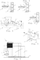
- FIGS 1 to 6 illustrate an exemplary embodiment of a machine 1 according to the invention and parts thereof.
- machine 1 is in position for dispensing a beverage 2.
- beverage 2 may be prepared from a receptacle containing a beverage ingredient and/or from loose beverage ingredient(s).
- Machine 1 has a beverage outlet 3 that is located above a dispensing area 4.
- Machine 1 includes a body or frame 5 having a first connecting part 51 and bearing beverage outlet 3.
- Machine 1 comprises a recipient support 6 having a second connecting part 61 and a support member 62 held, directly or indirectly, by second connecting part 61.
- Second connecting part 61 is disconnectably connectable to first connecting part 51 so that support member 62 extends into dispensing area 4 to support a beverage user-recipient 7 under beverage outlet 3.
- First connecting part 51 and second connecting part 61 have a connection member and a connection receiver arrangement, e.g. a plug and socket arrangement, for disconnectably connecting parts 51,61 such that: the first connecting part forms a connection member and the second connecting part forms a connection receiver; and/or first connecting part 51 forms a connection receiver and second connecting part 61 forms a connection member.
- connection member is inserted in the connection receiver when first and second connecting parts 51,61 are connected ( Figs 3 to 6 ).
- the connection member is removed from the connection receiver along a removal direction 51' when the first and second connecting parts 51,61 are disconnected ( Figs 1 and 4 ).
- Removal direction 51' has an upwardly directed vertical component 51" when such machine is in position to dispense beverage 2 ( Fig. 4 and 5 ).
- machine 1 is placed with a machine bottom 50 on an external generally horizontal support surface 8 ( Fig. 6 ).
- Upwardly directed vertical component 51" of removal direction 51' can be opposite to a vertical component of a force 71 exercised by user-recipient 7 on support member 62 when placed thereon under beverage outlet 3 ( Fig. 4 ).
- connection member can be in the shape generally of a rod or a bar extending along removal direction 51' when first and second connecting parts 51,61 are connected.
- the connection receiver can have a corresponding shape such that the connection member can be slid in an out of the receiver ( Figs 1 to 4 ).
- connection receiver and/or the connection member can have a connection approaching extremity 51a,61a, such as an insertion aperture 51a of the connection receiver or a free end 61a of the connection member, that allows for a mechanical positioning play between the connection member and the connection receiver when approaching each other at insertion ( Figs 1, 2 and 5 ).
- Approaching extremity 51a,61a may be tapered or flared, e.g. rounded or bevelled, to facilitate insertion of the connection member into the connection receiver ( Fig. 5 ).
- the receiver connection approaching extremity 51a may be flared and the member connection approaching extremity 61a may be tapered ( Fig. 5 ).
- Connection approaching extremity 51a,61a can be asymmetric to provide a mechanical positioning play only on an extremity play portion 51b,61b generally opposite to an extremity urging portion 51c,61c against which a main urging force 51′′′,51 ⁇ is exercised by first connecting part 51 on second connecting part 61 when second connecting part 61 is connected to first connecting part 51 ( Fig. 5 ).
- First connecting part 51 may exercise a first main urging force 51′′′ at connection approaching extremity 61a and a second main urging force 51"" at an extremity opposite thereto ( Fig. 5 ).
- connection member and the connection receiver can be secured in a cantilever manner by gravity force of support member 62 when such machine 1 is in position to dispense beverage 2: a or the above free end 61a of the connection member in the connection receiver is urged down (see arrow 51′′′ in Fig. 5 ) by the connection receiver and a or the above insertion aperture 51a of the connection receiver urges up (see arrow 51"" in Fig. 5 ) a or the extremity in the connection receiver of the connection member opposite free end 61a.
- Free end 61a and the extremity of the connection member opposite free end 61a can be further urged by gravity force 71 of beverage user-recipient 7 placed on support member 62.
- connection receiver and/or the connection member may have a or the above connection approaching extremity 51a,61a, such as a or the above insertion aperture 51a of the connection receiver or a or the above free end 61a of the connection member, that allows for a mechanical positioning play between the connection member and the connection receiver at insertion.
- approaching extremity 51a,61a is tapered or flared, e.g. rounded or bevelled, to facilitate insertion of the connection member into the connection receiver.
- the receiver connection approaching extremity 51a is flared and the member connection approaching extremity 61a is tapered.
- connection member within the connection receiver may have a convex shape and/or the connection receiver around the connection member may have a concave shape, the connection member and the connection receiver being for instance connectable together by a hook-free connection.
- connection member can have a shape extending all along within the connection receiver generally straight or arched along removal direction 51' when first and second connecting parts 51,61 are connected.
- the connection receiver may have a corresponding shape.
- connection member and the connection receiver may cooperate along a plain or roller bearing interface to connect and disconnect the member and the receiver.
- connection member and the connection receiver may be clamped together when first and second parts 51,61 are connected together.
- Support member 62 may have a recipient placement surface 62' for placing recipient 7 thereon under beverage outlet 3.
- Removal direction 51' can be angled away upwardly from a horizontal direction by an angle ⁇ in a range of 5 to 80 deg. such as 10 to 60 deg., for instance 15 to 45 deg., e.g. 25 to 35 deg., when first and second connecting parts 51,61 are connected and such machine 1 is in position to dispense beverage 2. See Figs 4 and 5 .
- Machine body or frame 5 can have a plurality of first connecting parts 51 that are vertically spaced apart for allowing recipient support 6 to be connected via its second connecting part 61 selectively at different corresponding heights under beverage outlet 3 ( Figs 1 to 3 ).
- recipient support 6 has a drop collection arrangement 63 for collecting drops from support member 62. See Fig. 4 .
- Collecting arrangement 63 may form a liquid reservoir for accumulating drops or a drain channel for evacuating drops e.g. to a service unit of machine 1.
- Collecting arrangement 63 can form a member that is separable from support member 62 or that is integral with the support member.
- Collecting arrangement 63 may form a member that is integral with second connecting part 61.
- Collecting arrangement 63 can be configured to collect drops draining via openings 62" of support member 62.
- Machine 1 may include one or more of: a control unit, such as a unit comprising a user-interface, for controlling active machine parts; an ingredient supply arrangement, such as a liquid source, e.g. a water tank 10 and/or a connector to a water supply line; a waste material collector 11, such as a waste ingredient collector and/or a waste ingredient receptacle collector; a fluid circuit, such as a circuit for guiding a fluid, e.g. water, from a liquid source 10 to the beverage outlet 3.
- a control unit such as a unit comprising a user-interface, for controlling active machine parts
- an ingredient supply arrangement such as a liquid source, e.g. a water tank 10 and/or a connector to a water supply line
- a waste material collector 11 such as a waste ingredient collector and/or a waste ingredient receptacle collector
- a fluid circuit such as a circuit for guiding a fluid, e.g. water, from a liquid source 10 to the beverage outlet
- Fluid circuit may incorporate a thermal conditioner, e.g. a heater and/or a cooler.
- Fluid circuit may include a pump, e.g. a solenoid pump or a membrane pump or a peristaltic pump, such as a low pressure pump e.g. operating within a range of 1 to 5 bar, such as 1.5 to 3 bar.
- Such fluid circuit may include an ingredient mixing unit 12 for producing beverage 2 and delivering such beverage 2 to beverage outlet 3.
- mixing unit 12 is configured for mixing liquid from source 10 with a flavouring ingredient, e.g. a flavouring ingredient supplied within a or the above receptacle into mixing unit 12.
- Mixing unit 12 may be arranged for mixing the liquid with the flavouring ingredient by rotational forces, e.g. by rotating mixing unit 12 when containing the liquid and the flavouring ingredient.
Landscapes
- Engineering & Computer Science (AREA)
- Food Science & Technology (AREA)
- Physics & Mathematics (AREA)
- Thermal Sciences (AREA)
- Devices For Dispensing Beverages (AREA)
- Apparatus For Making Beverages (AREA)
Claims (15)
- Maschine (1) zum Ausgeben eines Getränks (2), wie eines Getränks, das aus einem Aufnahmebehälter, der eine Getränkezutat enthält, zubereitet wird, umfassend:- einen Getränkeauslass (3), der sich oberhalb eines Ausgabebereichs (4) befindet;- einen Maschinenkörper oder -rahmen (5), der ein erstes Verbindungsteil (51) aufweist und den Getränkeauslass (3) trägt; und- eine Auffanggefäßstütze (6), die ein zweites Verbindungsteil (61) und ein Stützelement (62), das durch das zweite Verbindungsteil (61) direkt oder indirekt gehalten wird, aufweist,wobei das zweite Verbindungsteil (61) mit dem ersten Verbindungsteil (51) lösbar verbindbar ist, sodass sich das Stützelement (62) in den Ausgabebereich (4) erstreckt, um ein Benutzerauffanggefäß (7) für das Getränk unter dem Getränkeauslass (3) zu stützen, wobei das erste Verbindungsteil (51) und das zweite Verbindungsteil (61) ein Verbindungselement und eine Verbindungsaufnahmeanordnung aufweisen, die zum Beispiel eine Stecker- und Buchsenanordnung zum lösbaren Verbinden der Teile (51,61) ausbilden, derart, dass:- das erste Verbindungsteil ein Verbindungselement ausbildet und das zweite Verbindungsteil eine Verbindungsaufnahme ausbildet; oder- das erste Verbindungsteil (51) eine Verbindungsaufnahme ausbildet und das zweite Verbindungsteil (61) ein Verbindungselement ausbildet,wobei das Verbindungselement in die Verbindungsaufnahme eingeführt wird, wenn das erste und das zweite Verbindungsteil (51,61) verbunden werden, wobei das Verbindungselement von der Verbindungsaufnahme entlang einer Entnahmerichtung (51') entnommen wird, wenn das erste und das zweite Verbindungsteil (51,61) gelöst werden,wobei die Entnahmerichtung (51') eine nach oben gerichtete vertikale Komponente (51") aufweist, wenn eine solche Maschine (1) in der Position ist, um das Getränk (2) auszugeben, wie mit einem Maschinenboden (50) auf einer äußeren, im Wesentlichen horizontalen Stützoberfläche (8) platziert,wobei durch die Schwerkraft des Stützelements (62), wenn eine derartige Maschine (1) in der Position ist, um das Getränk (2) auszugeben, ein freies Ende (61a) des Verbindungselements in der Verbindungsaufnahme durch die Verbindungsaufnahme nach unten (51‴) gedrängt wird,dadurch gekennzeichnet, dass durch die Schwerkraft des Stützelements (62) eine Einführöffnung (51a) der Verbindungsaufnahme ein Ende in der Verbindungsaufnahme des Verbindungselements gegenüber dem freien Ende (61a) nach oben drängt (51ʺʺ), wodurch das Verbindungselement und die Verbindungsaufnahme auf freitragende Weise befestigt sind.
- Maschine nach Anspruch 1, wobei die nach oben gerichtete vertikale Komponente (51") der Entnahmerichtung (51') gegenüber einer vertikalen Komponente einer Kraft (71) gelegen ist, die durch das Benutzerauffanggefäß (7) auf das Stützelement (62) ausgeübt wird, wenn es darauf unter dem Getränkeauslass (3) platziert wird.
- Maschine nach einem der vorstehenden Ansprüche, wobei:- das Verbindungselement im Wesentlichen in der Form eines Stabs oder eines Balkens vorliegt, der sich entlang der Entnahmerichtung (51') erstreckt, wenn das erste und das zweite Verbindungsteil (51,61) verbunden sind; und- die Verbindungsaufnahme eine entsprechende Form aufweist, derart, dass das Verbindungselement in die Verbindungsaufnahme hinein- und aus dieser herausgeschoben werden kann.
- Maschine nach einem der vorstehenden Ansprüche, wobei die Verbindungsaufnahme und/oder das Verbindungselement ein Verbindungsvorlaufende (51a, 61a) aufweist, wie eine oder die Einführöffnung (51a) der Verbindungsaufnahme oder ein oder das freie Ende (61a) des Verbindungselements, das ein mechanisches Positionierungsspiel zwischen dem Verbindungselement und der Verbindungsaufnahme ermöglicht, wenn sie sich beim Einführen einander nähern, beispielsweise ist das Vorlaufende (51a, 61a) verjüngt oder aufgeweitet, zum Beispiel abgerundet oder abgeschrägt, um das Einführen des Verbindungselements in die Verbindungsaufnahme zu erleichtern, optional wobei das Verbindungsvorlaufende (51a) aufgeweitet ist und das Element des Verbindungsvorlaufendes (61a) verjüngt ist.
- Maschine nach Anspruch 4, wobei das Verbindungsvorlaufende (51a, 61a) asymmetrisch ist, um ein mechanisches Positionierungsspiel nur an einem Endspielabschnitt (51b, 61b) bereitzustellen, der im Wesentlichen einem Enddrängabschnitt (51c, 61c) gegenüberliegt, gegen den eine Hauptdrängkraft (51‴,51ʺʺ) durch das erste Verbindungsteil (51) auf das zweite Verbindungsteil (61) ausgeübt wird, wenn das zweite Verbindungsteil (61) mit dem ersten Verbindungsteil (51) verbunden ist.
- Maschine nach Anspruch 5, wobei das erste Verbindungsteil (51) eine erste Hauptdrängkraft (51‴) an dem Verbindungsvorlaufende (61a) und eine zweite Hauptdrängkraft (51ʺʺ) an einem dazu gegenüberliegenden Ende ausübt.
- Maschine nach einem der vorstehenden Ansprüche, wobei ein oder das freie Ende (61a) und das dem freien Ende (61a) gegenüberliegende Ende des Verbindungselements ferner durch die Schwerkraft (71) des Benutzerauffanggefäßes(7) für das Getränk, das auf dem Stützelement (62) platziert ist, gedrängt werden.
- Maschine nach einem der Ansprüche 3 bis 7, wobei die Verbindungsaufnahme und/oder das Verbindungselement ein oder das Verbindungsvorlaufende (51a, 61a) aufweist, wie eine oder die Einführöffnung (51a) der Verbindungsaufnahme oder ein oder das freie Ende (61a) des Verbindungselements, das ein mechanisches Positionierungsspiel zwischen dem Verbindungselement und der Verbindungsaufnahme bei Einführung ermöglicht, beispielsweise ist das Vorlaufende (51a, 61a) verjüngt oder aufgeweitet, zum Beispiel abgerundet oder abgeschrägt, um das Einführen des Verbindungselements in die Verbindungsaufnahme zu erleichtern, optional wobei das Verbindungsvorlaufende (51a) aufgeweitet ist und das Element des Verbindungsvorlaufendes (61a) verjüngt ist.
- Maschine nach einem der vorstehenden Ansprüche, wobei im vertikalen Querschnitt entlang der Entnahmerichtung (51') das Verbindungselement innerhalb der Verbindungsaufnahme eine konvexe Form aufweist oder die Verbindungsaufnahme um das Verbindungselement herum eine konkave Form aufweist, wobei das Verbindungselement und die Verbindungsaufnahme beispielsweise durch eine hakenfreie Verbindung miteinander verbindbar sind.
- Maschine nach einem der vorstehenden Ansprüche, wobei das Verbindungselement eine Form aufweist, die sich innerhalb der Verbindungsaufnahme im Wesentlichen gerade oder bogenförmig entlang der Entnahmerichtung (51') über die gesamte Länge erstreckt, wenn das erste und das zweite Verbindungsteil (51,61) verbunden sind, optional wobei die Verbindungsaufnahme eine entsprechende Form aufweist.
- Maschine nach einem der vorstehenden Ansprüche, wobei das Verbindungselement und die Verbindungsaufnahme:- entlang einer Gleit- oder Rollenlagerschnittstelle zusammenwirken, um das Element und die Aufnahme zu verbinden und zu lösen; und/oder- zusammengeklemmt werden, wenn das erste und das zweite Teil (51,61) miteinander verbunden werden.
- Maschine nach einem der vorstehenden Ansprüche, wobei das Stützelement (62) eine Platzierungsoberfläche (62') für das Auffanggefäß zum Platzieren des Auffanggefäßes (7) darauf unter dem Getränkeauslass (3) aufweist, und wobei die Entnahmerichtung (51') von einer horizontalen Richtung um einen Winkel (a) in einem Bereich von 5 bis 80 Grad, wie 10 bis 60 Grad, beispielsweise 15 bis 45 Grad, zum Beispiel 25 bis 35 Grad, nach oben weg abgewinkelt ist, wenn das erste und das zweite Verbindungsteil (51,61) verbunden sind und eine derartige Maschine (1) in der Position ist, um das Getränk (2) auszugeben.
- Maschine nach einem der vorstehenden Ansprüche, wobei der Maschinenkörper oder -rahmen (5) eine Vielzahl von ersten Verbindungsteilen (51) aufweist, die vertikal beabstandet sind, um zu ermöglichen, dass die Auffanggefäßstütze (6) über ihr zweites Verbindungsteil (61) in unterschiedlichen entsprechenden Höhen unter dem Getränkeauslass (3) wahlweise verbunden werden kann.
- Maschine nach einem der vorstehenden Ansprüche, wobei die Auffanggefäßstütze (6) eine Tropfenauffanganordnung (63) zum Auffangen von Tropfen von dem Stützelement (62) aufweist, optional wobei die Auffanganordnung (63):- einen Flüssigkeitsbehälter zum Ablagern von Tropfen oder einen Abflusskanal zum Ableiten von Tropfen, zum Beispiel zu einer Serviceeinheit einer derartigen Maschine (1), ausbildet;- ein Element ausbildet, das von dem Stützelement (62) trennbar ist oder das einstückig mit dem Stützelement ausgebildet ist;- ein Element, das mit dem zweiten Verbindungsteil (61) einstückig ist, ausbildet; und/oder- konfiguriert ist, um Tropfen aufzufangen, die über Öffnungen (62") des Stützelements (62) abfließen.
- Maschine nach einem der vorstehenden Ansprüche, die eines oder mehrere umfasst von: einer Steuereinheit, wie eine Einheit umfassend eine Benutzerschnittstelle, zum Steuern aktiver Maschinenteile; einer Zutatenversorgungsanordnung, wie eine Flüssigkeitsquelle, zum Beispiel ein Wassertank (10) und/oder ein Verbinder mit einer Wasserversorgungsleitung; einem Abfallmaterialsammler (11), wie ein Zutatenabfallsammler und/oder ein Zutatenabfallaufnahmesammelbehälter; einem Fluidkreislauf, wie ein Kreislauf zum Leiten eines Fluids, zum Beispiel Wasser, von einer Flüssigkeitsquelle (10) zu dem Getränkeauslass (3) über eines oder mehrere von:- einer thermischen Konditionierungseinrichtung, zum Beispiel eine Heizvorrichtung und/oder eine Kühlvorrichtung;- einer Pumpe, zum Beispiel eine Magnetpumpe oder eine Membranpumpe oder eine Schlauchpumpe, wie eine Niederdruckpumpe, die zum Beispiel in einem Bereich von 1 bis 5 bar, wie etwa 1,5 bis 3 bar, arbeitet; und- einer Zutatenmischeinheit (12) zum Herstellen des Getränks (2) und zum Liefern eines solchen Getränks (2) an den Getränkeauslass (3), beispielsweise eine Einheit zum Mischen von Flüssigkeit aus der Quelle (10) mit einer Geschmackszutat, zum Beispiel einer Geschmackszutat, die innerhalb des Aufnahmebehälters in die Mischeinheit (12) zugeführt wird, wie eine Einheit (12) zum Mischen der Flüssigkeit mit der Geschmackszutat durch Drehkräfte, zum Beispiel durch Drehen der Mischeinheit (12), wenn diese die Flüssigkeit und die Geschmackszutat enthält.
Applications Claiming Priority (2)
| Application Number | Priority Date | Filing Date | Title |
|---|---|---|---|
| EP18188315 | 2018-08-09 | ||
| PCT/EP2019/071324 WO2020030740A1 (en) | 2018-08-09 | 2019-08-08 | Easily insertable cup support |
Publications (2)
| Publication Number | Publication Date |
|---|---|
| EP3833227A1 EP3833227A1 (de) | 2021-06-16 |
| EP3833227B1 true EP3833227B1 (de) | 2024-11-13 |
Family
ID=63207656
Family Applications (1)
| Application Number | Title | Priority Date | Filing Date |
|---|---|---|---|
| EP19752486.1A Active EP3833227B1 (de) | 2018-08-09 | 2019-08-08 | Leicht einsetzbarer becherhalter |
Country Status (9)
| Country | Link |
|---|---|
| US (1) | US12070150B2 (de) |
| EP (1) | EP3833227B1 (de) |
| JP (1) | JP7504867B2 (de) |
| CN (1) | CN112512390B (de) |
| AU (1) | AU2019318450B2 (de) |
| CA (1) | CA3108829A1 (de) |
| ES (1) | ES3003917T3 (de) |
| PT (1) | PT3833227T (de) |
| WO (1) | WO2020030740A1 (de) |
Families Citing this family (5)
| Publication number | Priority date | Publication date | Assignee | Title |
|---|---|---|---|---|
| US11608259B2 (en) * | 2018-08-27 | 2023-03-21 | LNJ Group, LLC | Beverage dispensing machine and pouch for use with beverage dispensing machine |
| EP4346521A4 (de) * | 2021-05-26 | 2025-04-09 | Breville Pty Limited | Kaffeemaschine und milchtexturiervorrichtung |
| US20240398150A1 (en) | 2021-10-08 | 2024-12-05 | Societe Des Produits Nestle S.A. | Beverage preparation machine with simple ergonomic opening-closure |
| CA3233465A1 (en) | 2021-10-13 | 2023-04-20 | Laurent LAGOUCHE | Ergonomic beverage machine |
| GB202209989D0 (en) * | 2022-07-07 | 2022-08-24 | Schaal Marc | Container-based system for preparing and dispensing a custom beverage |
Citations (2)
| Publication number | Priority date | Publication date | Assignee | Title |
|---|---|---|---|---|
| DE202012006928U1 (de) * | 2012-07-18 | 2012-08-23 | Eugster/Frismag Ag | Getränkezubereitungsgerät, insbesondere Espressomaschine, mit einem höhenverstellbaren Auffanggefäßträger |
| EP2323523B1 (de) * | 2008-09-17 | 2012-10-10 | BSH Bosch und Siemens Hausgeräte GmbH | Halteeinrichtung |
Family Cites Families (81)
| Publication number | Priority date | Publication date | Assignee | Title |
|---|---|---|---|---|
| US2715868A (en) | 1951-11-23 | 1955-08-23 | Internat Coffee Corp | Coffee extracting and dispensing apparatus |
| US5161455A (en) | 1991-05-15 | 1992-11-10 | Bunn-O-Matic Corporation | Combination coffee and tea brewer |
| IT1252633B (it) | 1991-12-05 | 1995-06-19 | Gianmauro Zani | Macchina da caffe' compatta per caffe' espresso e per caffe' a caduta di acqua calda per filtrazione altrimenti detto caffe' all'americana. |
| DE4234746A1 (de) | 1992-10-15 | 1994-04-21 | Braun Ag | Pumpe für Haushaltsgeräte |
| US5353692A (en) | 1993-09-29 | 1994-10-11 | Unidynamics Corporation | Hot beverage brewing apparatus |
| FR2721381B1 (fr) | 1994-06-20 | 1996-08-02 | Seb Sa | Dispositif de production d'eau chaude ou de vapeur. |
| RU2185769C2 (ru) | 1995-12-28 | 2002-07-27 | Креахолик С.А. | Кофеварка |
| IT246634Y1 (it) | 1999-04-09 | 2002-04-09 | Ulka Srl | Pistone composito per pompa a vibrazione |
| US6459854B1 (en) | 2000-01-24 | 2002-10-01 | Nestec S.A. | Process and module for heating liquid |
| DK1380243T3 (da) | 2002-07-12 | 2008-08-25 | Nestec Sa | Indretning til opvarmning af en væske |
| GB2397503B (en) | 2003-01-24 | 2005-03-02 | Kraft Foods R & D Inc | Machine for the preparation of beverages |
| NL1023023C2 (nl) * | 2003-03-26 | 2004-09-30 | Bravilor Holding Bv | Inrichting voor het bereiden van heet water. |
| EP1634520A1 (de) | 2004-09-13 | 2006-03-15 | Nestec S.A. | Vorrichtung zur Heizung einer Flüssigkeit und Verfahren zum Erhitzen einer Flüssigkeit |
| DE102004046435A1 (de) | 2004-09-24 | 2006-04-27 | BSH Bosch und Siemens Hausgeräte GmbH | Kaffeemaschine und Pumpenhalterung für eine Kaffeemaschine |
| PT1656863E (pt) | 2004-11-11 | 2011-03-22 | Nestec Sa | Cabeça de mistura de limpeza automática para produção de uma mistura à base de leite e máquinas de produção de bebidas compreendendo esta cabeça de mistura |
| DE602005007475D1 (de) | 2005-06-07 | 2008-07-24 | Nestec Sa | Getränkemaschine mit Auffangwanne für Behälter unterschiedlicher Höhe |
| US20080307975A1 (en) * | 2005-12-15 | 2008-12-18 | Koninklijke Philips Electronics N.V. | Beverage Preparation Machine Having a Liquid Level Sensor |
| ATE556630T1 (de) | 2006-05-24 | 2012-05-15 | Nestec Sa | Brühvorrichtung für kapsel mit verschlussmechanismus mit variablem übersetzungsverhältnis |
| EP1867260B1 (de) | 2006-06-16 | 2010-05-26 | Nestec S.A. | Getränkeautomat mit Auflagesystem und Tropffänger für Behälter verschiedener Grössen |
| RU2474525C2 (ru) | 2007-06-05 | 2013-02-10 | Нестек С.А. | Капсула и способ приготовления пищевой жидкости с помощью центрифугирования |
| ATE540880T1 (de) | 2007-06-05 | 2012-01-15 | Nestec Sa | Einwegkapsel zur herstellung eines flüssigen nahrungsmittels durch zentrifugierung |
| CA2687894C (en) | 2007-06-05 | 2016-05-10 | Nestec S.A. | Capsule system, device and method for preparing a food liquid contained in a receptacle by centrifugation |
| CN101677706B (zh) | 2007-06-05 | 2013-07-17 | 雀巢产品技术援助有限公司 | 使用煮泡离心力的用于制备饮料或液态食品的方法和系统 |
| PL2000062T3 (pl) | 2007-06-05 | 2011-01-31 | Nestec Sa | Sposób przygotowywania napoju lub płynnej żywności oraz system wykorzystujący siłę odśrodkową do parzenia |
| ITFI20070172A1 (it) | 2007-07-24 | 2009-01-25 | Saeco Ipr Ltd | "un supporto per tazzine od altri contenitori in macchine per la produzione di bevande" |
| EP2027798A1 (de) | 2007-08-20 | 2009-02-25 | Nestec S.A. | Getränkeproduktionsmodul und Verfahren für den Betrieb eines Getränkeproduktionsmoduls |
| BRPI0821188B1 (pt) | 2007-12-12 | 2019-04-16 | Nestec S.A. | Receptáculo de cápsula ou saco usado para máquinas de alimento líquido ou bebida |
| EP2070454B1 (de) | 2007-12-12 | 2015-07-15 | Nestec S.A. | Modulare Herstellung von Getränkeherstellungsmaschinen |
| WO2009106589A1 (de) | 2008-02-26 | 2009-09-03 | Mann+Hummel Gmbh | Wirkungsgrad erhöhter mehrfachbalgfilter |
| US8978545B2 (en) | 2008-02-29 | 2015-03-17 | Nestec S.A. | Apparatus and method for preparing a beverage by centrifugation |
| BRPI0910773A2 (pt) | 2008-04-22 | 2015-09-29 | Nestec Sa | montagem modiular de uma máquina para preparo de bebidas |
| US8695484B2 (en) | 2008-05-07 | 2014-04-15 | Nestec S.A. | Used capsule collector for beverage devices |
| BRPI0912311A2 (pt) | 2008-05-28 | 2015-10-13 | Nestec Sa | bomba para dispositivos de preparação de bebidas líquidas. |
| US8479643B2 (en) | 2008-07-14 | 2013-07-09 | Nestec S.A. | Water circulation system for a beverage preparation device |
| US8512784B2 (en) | 2008-09-02 | 2013-08-20 | Nestec S.A. | Method and device for controlled beverage production using centrifugal forces |
| EP2330953B1 (de) | 2008-09-02 | 2015-06-03 | Nestec S.A. | Verfahren zur zubereitung einer in einer kapsel enthaltenen nahrungsmittelflüssigkeit durch zentrifugieren und für ein solches verfahren ausgelegtes system |
| RU2508895C2 (ru) | 2008-12-03 | 2014-03-10 | Нестек С.А. | Капсула для приготовления напитка методом центрифугирования |
| WO2010066736A1 (en) | 2008-12-09 | 2010-06-17 | Nestec S.A. | Liquid food preparation system for preparing a liquid food by centrifugation |
| AU2009326131B2 (en) | 2008-12-09 | 2015-10-08 | Société des Produits Nestlé S.A. | Capsule for preparing a beverage by centrifugation in a beverage preparation device and device adapted therefore |
| US9265376B2 (en) | 2009-02-06 | 2016-02-23 | Nestec S.A. | Device and method using centrifugation for extracting a liquid and heat loss compensating means |
| EP2228633B1 (de) | 2009-03-10 | 2017-07-05 | Nestec S.A. | Optischer Füllstandssensor für eine Getränkemaschine |
| US8863648B2 (en) | 2009-03-23 | 2014-10-21 | Nestec S.A. | Pump mount in a beverage preparation machine |
| AU2010244366A1 (en) | 2009-05-06 | 2011-12-08 | Nestec S.A. | Beverage machines with simplified servicing |
| CN104545474B (zh) | 2009-08-28 | 2017-05-31 | 雀巢产品技术援助有限公司 | 通过离心法制备饮料的胶囊系统 |
| US9084511B2 (en) * | 2009-10-22 | 2015-07-21 | Bunn-O-Matic Corporation | Flexible spray head |
| PT2521471E (pt) | 2010-01-06 | 2014-04-04 | Nestec Sa | Reservatório de água à prova de vibrações de uma máquina de bebidas |
| CN102802477B (zh) | 2010-01-15 | 2014-12-03 | 雀巢产品技术援助有限公司 | 符合人机工程学的成分保持器和维护单元配合 |
| IN2012DN06207A (de) | 2010-01-15 | 2015-09-25 | Nestec Sa | |
| ES2496767T5 (es) | 2010-01-21 | 2018-03-08 | Nestec S.A. | Máquina para bebidas, provista de un depósito extraíble de suministro de líquidos |
| JP2011167469A (ja) * | 2010-02-22 | 2011-09-01 | Makoto Takagi | コーヒー抽出器及びコーヒー抽出方法 |
| CA2790833A1 (en) | 2010-03-05 | 2011-09-09 | Nestec S.A. | Reduction of pump nuisance |
| JP2013529121A (ja) * | 2010-06-09 | 2013-07-18 | ネステク ソシエテ アノニム | 飲料装置のための人間工学的なサービス装置 |
| RU2013105685A (ru) | 2010-07-12 | 2014-08-20 | Нестек С.А. | Надежная подставка для чашек устройства для приготовления напитков |
| US9980597B2 (en) | 2010-12-01 | 2018-05-29 | Nestec S.A. | Beverage preparation machine with drop collector |
| EP2474254A1 (de) | 2011-01-07 | 2012-07-11 | Nestec S.A. | Modulares Getränkeausgabesystem |
| JP6271439B2 (ja) * | 2011-12-12 | 2018-01-31 | ネステク ソシエテ アノニム | 飲料ディスペンサ用のドリップトレイ |
| DE202011052332U1 (de) * | 2011-12-16 | 2013-03-19 | Wik Far East Ltd. | Vorratsbehälter zum Aufbewahren eines flüssigen Nahrungsmittels, etwa von Milch |
| JP6087955B2 (ja) | 2011-12-30 | 2017-03-01 | ネステク ソシエテ アノニム | マルチシステム飲料マシン |
| EP2633789A1 (de) | 2012-02-28 | 2013-09-04 | Nestec S.A. | Getränkezubereitungsmaschine mit Tropfenhandhabung |
| JP2015526122A (ja) * | 2012-06-15 | 2015-09-10 | ネステク ソシエテ アノニム | 振動抑制装置を有する飲料マシン |
| ES2676459T3 (es) | 2012-12-20 | 2018-07-19 | Nestec S.A. | Doble rampa para cerrar un soporte de receptáculo |
| EP2934247B1 (de) | 2012-12-20 | 2018-05-30 | Nestec S.A. | Variable übertragung zum schliessen eines behälterhalters |
| DE102013010110A1 (de) * | 2013-06-18 | 2014-12-18 | Beem Blitz-Elektro-Erzeugnisse Manufaktur Handels-Gmbh | Kaffeemaschine |
| WO2015096998A1 (en) | 2013-12-23 | 2015-07-02 | Nestec S.A. | Simple ergonomic user-interface for a beverage machine |
| EP3166457B1 (de) | 2014-07-09 | 2019-10-09 | Société des Produits Nestlé S.A. | Vorrichtung zum verbinden einer getränkemaschine mit einem verteilungsnetzwerk mit sicherer überwachung |
| EP3166455B1 (de) | 2014-07-09 | 2020-09-30 | Société des Produits Nestlé S.A. | Vorrichtung zum verbinden einer getränkemaschine mit einem verteilungsnetz mit sicherer strömungsunterbrechung |
| WO2016005349A1 (en) | 2014-07-09 | 2016-01-14 | Nestec S.A. | Accessory for supplying automatically a beverage machine with liquid from a distribution network |
| US10595670B2 (en) | 2014-07-09 | 2020-03-24 | Societe Des Produits Nestle S.A. | Coupling of a device for connecting a beverage machine to a distribution network |
| PT3232875T (pt) | 2014-12-18 | 2024-07-26 | Nestle Sa | Máquina de bebidas com suporte de chávena ligado de modo deslizante |
| PT3232877T (pt) | 2014-12-18 | 2020-04-23 | Nestle Sa | Máquina de bebidas com suporte de chávena com auto posicionamento |
| EP3232876A1 (de) | 2014-12-18 | 2017-10-25 | Nestec S.A. | Abnehmbare becherhalteplattform auf sammelbehälter |
| US9844293B2 (en) * | 2015-03-06 | 2017-12-19 | Spectrum Brands, Inc. | Apparatus for dispensing beverages |
| ES2726994T3 (es) * | 2015-03-09 | 2019-10-11 | Nestle Sa | Cabezal automatizado de inyección de fluido para un dispositivo para la preparación de bebidas |
| WO2016156364A1 (en) | 2015-04-02 | 2016-10-06 | Nestec S.A. | Shallow machine |
| EP3277139B1 (de) | 2015-04-02 | 2020-07-01 | Société des Produits Nestlé S.A. | Verschiebbarer becherträger |
| EP3277138B1 (de) | 2015-04-02 | 2021-01-06 | Société des Produits Nestlé S.A. | Arretierender becherträger |
| BR112018003224A2 (pt) | 2015-09-18 | 2018-09-25 | Nestec Sa | remoção de uma cápsula de um suporte de cápsula |
| EP3213662A1 (de) * | 2016-03-02 | 2017-09-06 | Nestec S.A. | Getränkemaschine |
| US10939780B2 (en) * | 2016-03-17 | 2021-03-09 | Eugster / Frismag Ag | Beverage preparation device and operating method |
| CN105686642B (zh) * | 2016-04-22 | 2019-01-29 | 施钟毓 | 带多仓胶囊座的咖啡机设备 |
| EP3463004B1 (de) | 2016-05-23 | 2023-11-22 | Société des Produits Nestlé S.A. | Entfernung von einer kapsel aus einem kapselhalter |
-
2019
- 2019-08-08 CA CA3108829A patent/CA3108829A1/en active Pending
- 2019-08-08 WO PCT/EP2019/071324 patent/WO2020030740A1/en not_active Ceased
- 2019-08-08 US US17/266,199 patent/US12070150B2/en active Active
- 2019-08-08 ES ES19752486T patent/ES3003917T3/es active Active
- 2019-08-08 AU AU2019318450A patent/AU2019318450B2/en active Active
- 2019-08-08 JP JP2021505960A patent/JP7504867B2/ja active Active
- 2019-08-08 EP EP19752486.1A patent/EP3833227B1/de active Active
- 2019-08-08 CN CN201980047132.0A patent/CN112512390B/zh active Active
- 2019-08-08 PT PT197524861T patent/PT3833227T/pt unknown
Patent Citations (2)
| Publication number | Priority date | Publication date | Assignee | Title |
|---|---|---|---|---|
| EP2323523B1 (de) * | 2008-09-17 | 2012-10-10 | BSH Bosch und Siemens Hausgeräte GmbH | Halteeinrichtung |
| DE202012006928U1 (de) * | 2012-07-18 | 2012-08-23 | Eugster/Frismag Ag | Getränkezubereitungsgerät, insbesondere Espressomaschine, mit einem höhenverstellbaren Auffanggefäßträger |
Also Published As
| Publication number | Publication date |
|---|---|
| US12070150B2 (en) | 2024-08-27 |
| ES3003917T3 (en) | 2025-03-11 |
| JP2021532921A (ja) | 2021-12-02 |
| EP3833227A1 (de) | 2021-06-16 |
| US20210251419A1 (en) | 2021-08-19 |
| CN112512390B (zh) | 2023-08-25 |
| AU2019318450B2 (en) | 2024-11-21 |
| WO2020030740A1 (en) | 2020-02-13 |
| JP7504867B2 (ja) | 2024-06-24 |
| PT3833227T (pt) | 2025-01-16 |
| CN112512390A (zh) | 2021-03-16 |
| CA3108829A1 (en) | 2020-02-13 |
| AU2019318450A1 (en) | 2021-01-07 |
Similar Documents
| Publication | Publication Date | Title |
|---|---|---|
| EP3833227B1 (de) | Leicht einsetzbarer becherhalter | |
| US9675205B2 (en) | Beverage machine for short and tall cups | |
| EP3232875B1 (de) | Getränkemaschine mit gleitend verbindbarem becherträger | |
| EP2861109B1 (de) | Getränkemaschine mit vibrationshemmer | |
| EP3232877B1 (de) | Getränkemaschine mit selbsteinstellendem becherhalter | |
| EP2802245B1 (de) | Getränkeautomat mit entfernbarem modul | |
| US11272805B2 (en) | Removable cup support platform on collector receptacle | |
| US10939779B2 (en) | Shallow machine | |
| EP4076107A1 (de) | Getränkeautomat mit betätigtem wasserversorgungsventil | |
| RU2799353C2 (ru) | Легко вставляемая подставка для чашки | |
| US20230027842A1 (en) | Beverage machine with separable beverage processing unit |
Legal Events
| Date | Code | Title | Description |
|---|---|---|---|
| STAA | Information on the status of an ep patent application or granted ep patent |
Free format text: STATUS: UNKNOWN |
|
| STAA | Information on the status of an ep patent application or granted ep patent |
Free format text: STATUS: THE INTERNATIONAL PUBLICATION HAS BEEN MADE |
|
| PUAI | Public reference made under article 153(3) epc to a published international application that has entered the european phase |
Free format text: ORIGINAL CODE: 0009012 |
|
| STAA | Information on the status of an ep patent application or granted ep patent |
Free format text: STATUS: REQUEST FOR EXAMINATION WAS MADE |
|
| 17P | Request for examination filed |
Effective date: 20210309 |
|
| AK | Designated contracting states |
Kind code of ref document: A1 Designated state(s): AL AT BE BG CH CY CZ DE DK EE ES FI FR GB GR HR HU IE IS IT LI LT LU LV MC MK MT NL NO PL PT RO RS SE SI SK SM TR |
|
| DAV | Request for validation of the european patent (deleted) | ||
| DAX | Request for extension of the european patent (deleted) | ||
| P01 | Opt-out of the competence of the unified patent court (upc) registered |
Effective date: 20230527 |
|
| GRAP | Despatch of communication of intention to grant a patent |
Free format text: ORIGINAL CODE: EPIDOSNIGR1 |
|
| STAA | Information on the status of an ep patent application or granted ep patent |
Free format text: STATUS: GRANT OF PATENT IS INTENDED |
|
| INTG | Intention to grant announced |
Effective date: 20240611 |
|
| GRAS | Grant fee paid |
Free format text: ORIGINAL CODE: EPIDOSNIGR3 |
|
| GRAA | (expected) grant |
Free format text: ORIGINAL CODE: 0009210 |
|
| STAA | Information on the status of an ep patent application or granted ep patent |
Free format text: STATUS: THE PATENT HAS BEEN GRANTED |
|
| AK | Designated contracting states |
Kind code of ref document: B1 Designated state(s): AL AT BE BG CH CY CZ DE DK EE ES FI FR GB GR HR HU IE IS IT LI LT LU LV MC MK MT NL NO PL PT RO RS SE SI SK SM TR |
|
| REG | Reference to a national code |
Ref country code: GB Ref legal event code: FG4D |
|
| REG | Reference to a national code |
Ref country code: CH Ref legal event code: EP |
|
| REG | Reference to a national code |
Ref country code: IE Ref legal event code: FG4D |
|
| REG | Reference to a national code |
Ref country code: DE Ref legal event code: R096 Ref document number: 602019061945 Country of ref document: DE |
|
| REG | Reference to a national code |
Ref country code: PT Ref legal event code: SC4A Ref document number: 3833227 Country of ref document: PT Date of ref document: 20250116 Kind code of ref document: T Free format text: AVAILABILITY OF NATIONAL TRANSLATION Effective date: 20250110 |
|
| REG | Reference to a national code |
Ref country code: NL Ref legal event code: FP |
|
| REG | Reference to a national code |
Ref country code: LT Ref legal event code: MG9D |
|
| REG | Reference to a national code |
Ref country code: ES Ref legal event code: FG2A Ref document number: 3003917 Country of ref document: ES Kind code of ref document: T3 Effective date: 20250311 |
|
| PG25 | Lapsed in a contracting state [announced via postgrant information from national office to epo] |
Ref country code: IS Free format text: LAPSE BECAUSE OF FAILURE TO SUBMIT A TRANSLATION OF THE DESCRIPTION OR TO PAY THE FEE WITHIN THE PRESCRIBED TIME-LIMIT Effective date: 20250313 Ref country code: HR Free format text: LAPSE BECAUSE OF FAILURE TO SUBMIT A TRANSLATION OF THE DESCRIPTION OR TO PAY THE FEE WITHIN THE PRESCRIBED TIME-LIMIT Effective date: 20241113 |
|
| PG25 | Lapsed in a contracting state [announced via postgrant information from national office to epo] |
Ref country code: FI Free format text: LAPSE BECAUSE OF FAILURE TO SUBMIT A TRANSLATION OF THE DESCRIPTION OR TO PAY THE FEE WITHIN THE PRESCRIBED TIME-LIMIT Effective date: 20241113 |
|
| PG25 | Lapsed in a contracting state [announced via postgrant information from national office to epo] |
Ref country code: BG Free format text: LAPSE BECAUSE OF FAILURE TO SUBMIT A TRANSLATION OF THE DESCRIPTION OR TO PAY THE FEE WITHIN THE PRESCRIBED TIME-LIMIT Effective date: 20241113 |
|
| PG25 | Lapsed in a contracting state [announced via postgrant information from national office to epo] |
Ref country code: NO Free format text: LAPSE BECAUSE OF FAILURE TO SUBMIT A TRANSLATION OF THE DESCRIPTION OR TO PAY THE FEE WITHIN THE PRESCRIBED TIME-LIMIT Effective date: 20250213 |
|
| PG25 | Lapsed in a contracting state [announced via postgrant information from national office to epo] |
Ref country code: GR Free format text: LAPSE BECAUSE OF FAILURE TO SUBMIT A TRANSLATION OF THE DESCRIPTION OR TO PAY THE FEE WITHIN THE PRESCRIBED TIME-LIMIT Effective date: 20250214 Ref country code: LV Free format text: LAPSE BECAUSE OF FAILURE TO SUBMIT A TRANSLATION OF THE DESCRIPTION OR TO PAY THE FEE WITHIN THE PRESCRIBED TIME-LIMIT Effective date: 20241113 |
|
| PG25 | Lapsed in a contracting state [announced via postgrant information from national office to epo] |
Ref country code: PL Free format text: LAPSE BECAUSE OF FAILURE TO SUBMIT A TRANSLATION OF THE DESCRIPTION OR TO PAY THE FEE WITHIN THE PRESCRIBED TIME-LIMIT Effective date: 20241113 |
|
| PG25 | Lapsed in a contracting state [announced via postgrant information from national office to epo] |
Ref country code: RS Free format text: LAPSE BECAUSE OF FAILURE TO SUBMIT A TRANSLATION OF THE DESCRIPTION OR TO PAY THE FEE WITHIN THE PRESCRIBED TIME-LIMIT Effective date: 20250213 |
|
| PG25 | Lapsed in a contracting state [announced via postgrant information from national office to epo] |
Ref country code: SM Free format text: LAPSE BECAUSE OF FAILURE TO SUBMIT A TRANSLATION OF THE DESCRIPTION OR TO PAY THE FEE WITHIN THE PRESCRIBED TIME-LIMIT Effective date: 20241113 |
|
| PG25 | Lapsed in a contracting state [announced via postgrant information from national office to epo] |
Ref country code: DK Free format text: LAPSE BECAUSE OF FAILURE TO SUBMIT A TRANSLATION OF THE DESCRIPTION OR TO PAY THE FEE WITHIN THE PRESCRIBED TIME-LIMIT Effective date: 20241113 |
|
| PG25 | Lapsed in a contracting state [announced via postgrant information from national office to epo] |
Ref country code: EE Free format text: LAPSE BECAUSE OF FAILURE TO SUBMIT A TRANSLATION OF THE DESCRIPTION OR TO PAY THE FEE WITHIN THE PRESCRIBED TIME-LIMIT Effective date: 20241113 |
|
| PG25 | Lapsed in a contracting state [announced via postgrant information from national office to epo] |
Ref country code: RO Free format text: LAPSE BECAUSE OF FAILURE TO SUBMIT A TRANSLATION OF THE DESCRIPTION OR TO PAY THE FEE WITHIN THE PRESCRIBED TIME-LIMIT Effective date: 20241113 |
|
| PG25 | Lapsed in a contracting state [announced via postgrant information from national office to epo] |
Ref country code: SK Free format text: LAPSE BECAUSE OF FAILURE TO SUBMIT A TRANSLATION OF THE DESCRIPTION OR TO PAY THE FEE WITHIN THE PRESCRIBED TIME-LIMIT Effective date: 20241113 |
|
| PG25 | Lapsed in a contracting state [announced via postgrant information from national office to epo] |
Ref country code: CZ Free format text: LAPSE BECAUSE OF FAILURE TO SUBMIT A TRANSLATION OF THE DESCRIPTION OR TO PAY THE FEE WITHIN THE PRESCRIBED TIME-LIMIT Effective date: 20241113 |
|
| REG | Reference to a national code |
Ref country code: DE Ref legal event code: R097 Ref document number: 602019061945 Country of ref document: DE |
|
| PGFP | Annual fee paid to national office [announced via postgrant information from national office to epo] |
Ref country code: NL Payment date: 20250704 Year of fee payment: 7 |
|
| PG25 | Lapsed in a contracting state [announced via postgrant information from national office to epo] |
Ref country code: SE Free format text: LAPSE BECAUSE OF FAILURE TO SUBMIT A TRANSLATION OF THE DESCRIPTION OR TO PAY THE FEE WITHIN THE PRESCRIBED TIME-LIMIT Effective date: 20241113 |
|
| PLBE | No opposition filed within time limit |
Free format text: ORIGINAL CODE: 0009261 |
|
| STAA | Information on the status of an ep patent application or granted ep patent |
Free format text: STATUS: NO OPPOSITION FILED WITHIN TIME LIMIT |
|
| PGFP | Annual fee paid to national office [announced via postgrant information from national office to epo] |
Ref country code: PT Payment date: 20250807 Year of fee payment: 7 Ref country code: ES Payment date: 20250905 Year of fee payment: 7 |
|
| PGFP | Annual fee paid to national office [announced via postgrant information from national office to epo] |
Ref country code: DE Payment date: 20250702 Year of fee payment: 7 |
|
| PGFP | Annual fee paid to national office [announced via postgrant information from national office to epo] |
Ref country code: IT Payment date: 20250722 Year of fee payment: 7 |
|
| PGFP | Annual fee paid to national office [announced via postgrant information from national office to epo] |
Ref country code: BE Payment date: 20250703 Year of fee payment: 7 Ref country code: GB Payment date: 20250703 Year of fee payment: 7 |
|
| PGFP | Annual fee paid to national office [announced via postgrant information from national office to epo] |
Ref country code: FR Payment date: 20250703 Year of fee payment: 7 Ref country code: AT Payment date: 20250725 Year of fee payment: 7 |
|
| PGFP | Annual fee paid to national office [announced via postgrant information from national office to epo] |
Ref country code: CH Payment date: 20250901 Year of fee payment: 7 |
|
| 26N | No opposition filed |
Effective date: 20250814 |
|
| REG | Reference to a national code |
Ref country code: AT Ref legal event code: UEP Ref document number: 1740956 Country of ref document: AT Kind code of ref document: T Effective date: 20241113 |
|
| PG25 | Lapsed in a contracting state [announced via postgrant information from national office to epo] |
Ref country code: MC Free format text: LAPSE BECAUSE OF FAILURE TO SUBMIT A TRANSLATION OF THE DESCRIPTION OR TO PAY THE FEE WITHIN THE PRESCRIBED TIME-LIMIT Effective date: 20241113 |
|
| PG25 | Lapsed in a contracting state [announced via postgrant information from national office to epo] |
Ref country code: LU Free format text: LAPSE BECAUSE OF NON-PAYMENT OF DUE FEES Effective date: 20250808 |