EP3833305B1 - Kippbare werkzeuge für herzklappenprothese - Google Patents
Kippbare werkzeuge für herzklappenprothese Download PDFInfo
- Publication number
- EP3833305B1 EP3833305B1 EP18762926.6A EP18762926A EP3833305B1 EP 3833305 B1 EP3833305 B1 EP 3833305B1 EP 18762926 A EP18762926 A EP 18762926A EP 3833305 B1 EP3833305 B1 EP 3833305B1
- Authority
- EP
- European Patent Office
- Prior art keywords
- axis
- heart valve
- holder
- central pin
- valve assembly
- Prior art date
- Legal status (The legal status is an assumption and is not a legal conclusion. Google has not performed a legal analysis and makes no representation as to the accuracy of the status listed.)
- Active
Links
Images


Classifications
-
- A—HUMAN NECESSITIES
- A61—MEDICAL OR VETERINARY SCIENCE; HYGIENE
- A61F—FILTERS IMPLANTABLE INTO BLOOD VESSELS; PROSTHESES; DEVICES PROVIDING PATENCY TO, OR PREVENTING COLLAPSING OF, TUBULAR STRUCTURES OF THE BODY, e.g. STENTS; ORTHOPAEDIC, NURSING OR CONTRACEPTIVE DEVICES; FOMENTATION; TREATMENT OR PROTECTION OF EYES OR EARS; BANDAGES, DRESSINGS OR ABSORBENT PADS; FIRST-AID KITS
- A61F2/00—Filters implantable into blood vessels; Prostheses, i.e. artificial substitutes or replacements for parts of the body; Appliances for connecting them with the body; Devices providing patency to, or preventing collapsing of, tubular structures of the body, e.g. stents
- A61F2/02—Prostheses implantable into the body
- A61F2/24—Heart valves ; Vascular valves, e.g. venous valves; Heart implants, e.g. passive devices for improving the function of the native valve or the heart muscle; Transmyocardial revascularisation [TMR] devices; Valves implantable in the body
- A61F2/2427—Devices for manipulating or deploying heart valves during implantation
Definitions
- the present disclosure relates generally to a prosthetic mitral valve, implantation accessories, and associated implant methods.
- Background documents in this technical field include i.a. US 2015/327998 A1 , US 2017/020527 A1 , and US 2018/116795 A1 .
- Prosthetic heart valves can replace defective human valves in patients.
- Prosthetic heart valves come in two varieties: bioprosthetic (e.g., tissue) heart valves and mechanical heart valves.
- tissue e.g., tissue
- mechanical heart valves e.g., a mechanical heart valve
- valve prostheses are typically sutured to peripheral tissue of a natural heart valve orifice (the "annulus") after surgical removal of damaged or diseased natural valve structure.
- the sewing ring of the prosthetic valve may be secured to the annulus via sutures.
- This procedure can be very complicated, as surgeons are manipulating multiple sutures and small components while working in tight spaces with limited visibility. The difficulties can be even greater with the implementation of tissue valves, given their shape and construction.
- the commissure posts are the first portion of the valve entering inside the patient's annulus during valve delivery.
- suture looping commonly referred to as "suture looping"
- the commissure posts are not visible at this point during the procedure, the surgeon cannot visually detect whether any such entanglement has occurred. This problem is even more pronounced during a minimally-invasive access approach, a technique that is quickly becoming more common in the industry, which provides even more limited visibility of the surgical field during valve delivery.
- MICS minimally invasive cardiothoracic surgery
- the present device and method can be utilized to improve implantation procedures and performance of heart valve prostheses in a wide variety of applications where the heart valve prosthesis is surgically attached to a prepared valvular rim (or annulus).
- the embodiments disclosed herein are directed to improved removable bioprosthetic heart valves for implantation into an implantable abutment ring, the removable bioprosthetic heart valve comprising a valve frame having tissue leaflets attached thereto (or alternatively, a mechanical pivotal disk or mechanical leaflets or equivalents thereof).
- the various aspects of the present invention may be utilized in mitral valve (or other heart valve-aortic, etc.) replacement wherein a prosthetic heart valve frame operates in accordance with a suture ring.
- FIG. 1 a schematic view illustrating a removable bioprosthetic heart valve assembly 250 and implantation into a patient, according to some embodiments described in the disclosure.
- the removable prosthetic heart valve assembly 250 is a bioprosthetic (i.e., tissue) heart valve assembly.
- tissue valves generally include a plurality of tissue cusps or leaflets, e.g., made from bovine pericardium or harvested porcine heart valve tissue, mounted onto a stationary metal or plastic frame structure. This frame structure operates to maintain the various cusps or leaflets in a desired orientation and shape that promotes sufficient valve opening and closing characteristics and proper blood flow.
- the prosthetic heart valve assembly 250 is a mechanical heart valve assembly.
- a modern mechanical heart valve prosthesis is typically formed of an annular valve seat in a relatively rigid valve body and includes an occluding disk or pair of leaflets that moves between a closed, seated position and an open position in a prescribed range of motion.
- bioprosthetic heart valves As shown in FIGS. 1-6 . It should be appreciated, however, that mechanical heart valves (as shown in FIGS. 7 and 8 ) may also be employed with the embodiments discussed herein, and that reference to bioprosthetic heart valves should not serve to limit the teaching of this disclosure.
- removable bioprosthetic heart valve assembly 250 for implantation into an implantable abutment ring 50 includes valve frame 200 having tissue leaflets therein and holder 100. As discussed in greater detail below, abutment ring 50 is configured to receive valve frame 200, and valve frame 200 is configured to be received by abutment ring 50. Together, holder 100, valve frame 200, and a plurality of tissue leaflets (not shown) located within the valve frame 200 generally make up the structure of the removable bioprosthetic heart valve assembly 250. Together, removable bioprosthetic heart valve assembly 250 and abutment ring 50 generally make a multiple component heart valve prosthesis 280 for implantation at a heart valve annulus location of a patient's heart, in its assembled configuration.
- removable bioprosthetic heart valve assembly 250 includes holder 100 for maneuvering and implanting valve frame 200 into abutment ring 50.
- holder 100 is detachable and removable after successful implantation of valve frame 200 into abutment ring 50.
- Valve frame 200 is interchangeably referred to herein as valve 200, and it is understood that valve or valve frame 200 further includes a plurality of tissue leaflets located within the valve frame 200.
- removable bioprosthetic heart valve assembly 250 for implantation into abutment ring 50 is attached at heart valve annulus location 30 of a patient's heart.
- Patient 10 in a minimally-invasive access approach, for example, is entered through patient chest opening 12 to access ventricle 20.
- Abutment ring 50 is secured to patient annulus 30.
- Abutment ring 50 includes axis A1 passing through its center.
- Axis A1 is generally perpendicular to the annulus.
- Removable bioprosthetic heart valve assembly 250 comprises bioprosthetic valve 200 for coupling to abutment ring 50, and holder 100 detachably coupled to valve 200.
- holder 100 is coupled also to handle 300 via fit joint (160, shown in FIG. 2B ).
- Holder 100, coupled to valve 200 includes surface 110 and axis A2.
- Axis A2 is perpendicular to surface 110.
- Surface 110 is planar and disc shaped to couple with valve 200.
- axis A2 is offset to axis A1 by angle 60.
- Angle 60 is an acute angle, ranging in measurement from less than 90 degrees but more than zero degrees.
- Holder 100 further includes maneuvering system 120 ( FIG.
- Holder 100 having maneuvering system 120, is interchangeably referred to herein as tiltable holder 100.
- abutment ring 50 is attachable to a patient's mitral valve rim.
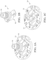
- FIG. 2A is a perspective view illustrating holder 100 and fit joint 160 for removable bioprosthetic heart valve assembly 250 as shown in FIG. 1 .
- Holder 100 is coupled to fit joint 160.
- FIG. 2B is a perspective view illustrating fit joint 160 as in FIG. 2A .
- Fit joint 160 includes proximal end 162 and distal end 164, proximal end 162 is configured for coupling to holder 100 and distal end 164 is configured for coupling to elongated handle 300 (as shown in FIG. 1 ).
- Fit joint 160 is detachable as needed.
- fit joint 160 detaches from holder 100 to allow access to maneuvering system 120 by the physician using, for example, MICS forceps.
- FIG. 2C is a perspective view illustrating holder 100 for detachable coupling to fit joint 160 as in FIG. 2B .
- Holder 100 is interchangeably referred to herein as holder template.
- FIG. 3 is a perspective view illustrating holder 100 of removable bioprosthetic heart valve assembly 250.
- Holder 100 having axis A2, includes surface 110 and maneuvering system 120.
- Maneuvering system 120 includes central pin 130 pivotable relative to holder 100, pivoting as indicated by direction 70. Axis A2 passes through central pin 130. Central pin 130 is further rotatable with the holder in a first clockwise direction D1 and in a second counter-clockwise direction D2. In some embodiments, central pin 130 is attachable to a minimally invasive cardiothorasic surgery (MICS) forceps for ease in maneuverability.
- Maneuvering system 120 further includes threadable arcuate bores 140 and 150. Each threadable arcuate bore, bores 140 and 150, include first and second openings disposed at surface 110. Bore 140 includes openings 142 and 144. Bore 150 includes openings 152 and 154.
- FIG. 4 is a perspective view illustrating holder 100 of removable bioprosthetic heart valve assembly 250.
- Threadable arcuate bore 140 and threadable arcuate bore 150 include threads 146 and 156 therethrough, respectively.
- Manipulation or pulling on threads 146 and 156, while grasping the central pin 130 e.g., with a MICS forceps, operate to tilt surface 110 and aligning axis A1 and axis A2.
- Surface 110 is tiltable about axis z (see coordinates 180), which extends parallel to the central pin 130.
- surface 110 is maneuverable to align axes A1 and A2 when holder 100 and valve 200, as coupled, are proximate abutment ring 50.
- a retaining surgical suture may be attached to at least one of the bores 140, 150. This retaining suture may extend to outside the patient (e.g., to the surgeon) and may be used to ensure the device does not get lost inside the patient.
- FIG. 4 also illustrates holes 180 through the thickness of holder 100, the holes extending from surface 110 to surface 210 opposite thereof. These holes enable coupling of holder 100 to valve 200 and include sutures 170, 172, and 174 for attachment as shown in FIG. 4 .
- sutures 170, 172, and 174 can be cut after successful seating and securing of valve 200 into abutment ring 50.
- holder 100 is detachable and able to be removed from the patient.
- Holders 100 are sized according to patient valve requirements and are generally formed of a biocompatible metal (e.g., titanium, stainless steel, or other suitable metal alloy), a plastic material (e.g., acetal homopolymer plastic) or of any other suitable biocompatible material. Holder 100 is detachable and disposable, suitable for single-use.
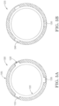
- FIG. 5A and 5B are top-views of removable bioprosthetic heart valve assembly 250 according to some embodiments.
- heart valve assembly 250 includes a two-piece mechanical heart valve.
- FIG. 5A illustrates abutment ring 1050 and valve frame 1200 in a disengaged configuration 1250.
- Abutment ring 1050 includes locking system 1220.
- locking system 1220 includes one or more notches capable of accepting locking features on valve frame 1200, along with a channel extending between the notches to allow rotation of the locking features through the channel to a position not aligned with the notches in the locking system to an engaged position (also referred to herein as a "locked" position).
- Valve frame 1200 includes at least one locking feature 1230. As shown in FIG. 5A , the valve frame 1200 includes three locking features, which protrude radially outward to mate with the valve system 1220.
- FIG. 5B illustrates abutment ring 1050 and valve frame 1200 in an engaged configuration 1260.
- the at least one locking feature 1230 is configured to be received by the locking system, for example by channel 1240 of abutment ring 1050 extending between the notches.
- International Application No. PCT/IB2016/053515 describes locking systems suitable in removable bioprosthetic valve assemblies according to at least some embodiments of the present disclosure.
- the maneuvering system having central pin may be used to rotate the valve frame 1200 relative to the abutment ring 1050 in a first (e.g., clockwise) direction into the locked position.
- the maneuvering system may be used to rotate the valve from 1200 relative to the abutment ring 1050 in a second (e.g., counter-clockwise) direction to a disengaged position.
- a second (e.g., counter-clockwise) direction to a disengaged position.
- This enables the valve to be seated and secured to the abutment ring after alignment of axes A1 and A2.
- it conversely allows the valve to be disengaged and removed from the abutment ring.
- an implantation accessory such as a sizer is introduced into the native valve annulus in order to evaluate the size of the annulus.
- multiple sizers having different dimensions are introduced independently for annulus size determination.
- the medical team may have three or four sizers of varying dimensions available to perform the sizing procedure with sizer 500. That way, an appropriate sized corresponding holder/valve assembly can be selected by the medical team that best fits the native valve annulus, thus ensuring a successful procedure, which include (among others) implantation of a bioprosthetic heart valve, a mechanical heart valve and an annuloplasty ring.
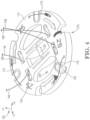
- FIG. 6 is a perspective view illustrating a sizer 500 for determining annulus size.
- Sizer 500 which may also be referred to interchangeably herein as D-shaped sizer 500, is designed to complement a D-shaped mitral annulus, for example.
- D-shaped refers to an approximate shape including a long side 510 and a curved profile side 520.
- Side 510 is generally placed anteriorly in the patient, while side 520 is generally placed posteriorly.
- Sizer 500 includes a long axis A3 and a short axis A4 as shown on FIG. 6 .
- long axis A3 of sizer 500 ranges from 24 mm to 42 mm.
- the long axis A3 is 24 mm, or 26 mm, or 28 mm, or 30 mm, or 32 mm, or 34 mm, or 36 mm, or 38 mm, or 40 mm, or 42 mm.
- the ratio of the long axis to the short axis A3/A4 ranges from 1.3 to 1.5.
- sizer 500 for use with mitral valve prosthesis and annuloplasty rings provides for minimally invasive procedures with a reduced height for insertion through a small wound, as for example in a MICS procedure.
- sizer 500 is shaped such that it corresponds to the shape of the native valve annulus, while also having a thickness capable of insertion through a space between the ribs of the patient during the procedure.
- sizer 500 includes central pin 530 for grasping and maneuvering with a MICS forceps.
- FIG. 6 also illustrates holes 580 and 585 through the thickness of sizer 500, the holes extending from surface 560 to surface 570 opposite thereof.
- Threadable holes 580 and 585 are for inserting threads therethrough (i.e. one thread through holes 580 and a second thread through holes 585). Threads passing through holes or openings 580 and 585 can also be used for maneuvering the sizer, i.e. tipping or angling surface 560, by pulling or maneuvering the threads in similar manner as for threadable arcuate bores 140 and 150 for holder 100 of FIG. 4 .
- the threads are also used to help ensure the sizer 500 is not left behind in the patient.
- holes 580 is referred to interchangeably herein as a first threadable bore formed by the pair of holes 580; and holes 585 is referred to interchangeably herein as a second threadable bore formed by the pair of holes 585.
- Maneuvering system 520 including central pin 530 and threadable holes 580 and 585, operates similarly as described for system 120 for holder 100.
- Sizer 500 further includes bores or slots 540 and 550, slots 540 and 550 configured to allow coupling of the central fit joint to the sizes 500, in a manner as described similarly as shown for fit joint 160 of FIG. 2B .
- Such parachuting may also be accomplished using a MICS forceps to engage the central pin 530.
- Surface 570 of sizer 500 is placed adjacent to and/or in contact with the patient's annulus during sizing, while surface 560 faces the direction of the physician performing the sizing.
- the fit joint may be removed to allow the sizer to be tilted for insertion through a small incision.
- an implantation accessory for placement at a patient's heart valve annulus location includes a mechanical heart valve for placement at a patient's native valve annulus.
- the native valve annulus can be at an aortic valve or at a mitral valve location.
- the implantation accessory includes a rotator to rotate the already implanted valve in order to orient or reposition the leaflet(s) of the mechanical heart valve.
- implantation accessory 700 is shown for implantation into mechanical heart valve 850, which includes valve housing attached at heart valve annulus location 30 of a patient's heart. Valve 850 is also referred to as valve housing 850 interchangeably herein.
- Implantation accessory 700 is also referred to interchangeably herein as rotator 700 or as holder 700. Using rotator 700, the valve 850 rotates within its housing for fine tuning and leaflet orientation after valve implantation.
- Implantation assembly 650 includes mechanical heart valve 850 (see FIGS. 8A and 8F ) and rotator 700. Valve 850 further includes leaflets 860.
- Multiple component heart valve accessory 780 includes rotator 700 and fit joint 760, which may be similar to the above-described fit joint 160. Fit joint 760 is attachable to handle 300.
- Patient 10 in a minimally-invasive access approach, for example, is entered through patient chest opening 12 to access ventricle 20.
- Mechanical heart valve 850 is secured to patient annulus 30 and includes axis A1 passing through its center as shown in FIG. 7 . Axis A1 is generally perpendicular to the annulus. Once secured to annulus 30, there is limited access to valve 850 due to physical constraints within patient 10, thus making positioning of mechanical heart valve 850 and orientation of leaflets
- implantation assembly 650 comprises mechanical valve 650 (coupled with valve housing 850) and rotator 700 detachably coupled to valve 850.
- rotator 700 is coupled also to handle 300 via fit joint 760 as shown in FIG. 8A .
- Fit joint 760 and rotator 700 are two separate components shown coupled together in FIG. 8A .
- Rotator 700 is further useful in rotating or aligning leaflets 860 within valve housing 850 by using maneuvering system 720.
- Implantation accessory 780 as shown in the exploded view of FIG. 8B , includes rotator 700 having central pin 730, the rotator 700 attachable to fit joint 760.
- Component 700 which is a rotator or holder, includes central pin 730.
- Fit joint 760 is useful for valve placement by a physician when an open chest is accessible wherein holder 780 is used assembled. In a minimally invasive procedure, the fit joint 760 is removed outside of the patient before insertion of the assembly so that only the rotator 700 remains on the valve, thereby reducing the height of the implantation accessory and allowing insertion through a small wound. In the embodiments disclosed herein, fit joint 760 is removed prior to implantation and, therefore, the maneuvering system 720 is fully exposed and accessible to be used by the physician in a similar manner as for maneuvering system 120 as detailed above.
- Central pin 730 operates similarly as described for central pin 130 for holder 100 and is graspable by forceps.
- Rotator 700 includes holes 770 and 775. Holes 770 and 775 allow fixing the valve 850 to holder 700 by threading threads therethrough and is also referred to as a retaining system to affix to a valve. Teeth 758 of fit joint 760 facilitate coupling to rotator 700 via a snap fit connection wherein teeth 758 mate with holes 745 of holder 700. After the valve 850 has been detached from rotator 700, both holes 770 are used to insert the surgical thread by the physician to tilt the holder as part of maneuvering system 720 working in conjunction with forceps grasping the rotatable central pin 730.
- rotator 700 includes surface 710 and axis A2.
- Axis A2 is perpendicular to surface 710.
- Surface 710 is planar and disk shaped to couple with valve 850.
- axis A2 is offset to axis A1 by at an acute angle, angle 60, ranging in measurement from less than 90 degrees but more than zero degrees.
- Rotator 800 is similar to rotator 700 of FIG. 8B except that rotator 800 having maneuvering system 820 includes threadable arcuate bores 840 and 845, the bores being threadable for tilting the rotator similarly as for arcuate bores 140 and 150 for holder 100 as detailed above and as shown in FIG. 4 .
- Rotator 800 includes maneuvering system 820 for aligning axis A2 with axis A1, maneuvering system 820 including central pin 730. Alignment of axes A1 and A2 prior to seating of valve 850 ensures proper implantation of valve 850 and orientation of valve leaflets 860, which may be metallic, into valve housing 850.
- Implantation accessory 800 is configured to position a plurality of leaflets 860 of the removable mechanical heart valve assembly 850. Positioning leaflets includes at least one of pivoting and tilting. Rotator 800 is interchangeably referred to herein as tiltable rotator 800.
- valve housing 850 is attachable to a patient's mitral valve rim via a sewing cuff. In other embodiments, valve housing 850 is attachable to a patient's aortic valve rim.
- central pin 730 is attachable to a minimally invasive cardiothorasic surgery (MICS) forceps.
- MIMS minimally invasive cardiothorasic surgery
- rotator 800 includes central pin 730 for grasping and maneuvering with a MICS forceps. While grasping central pin 730 with minimally invasive cardiothoracic surgery (MICS) forceps is not shown in FIGS. 8A - 8F , central pin 730 is graspable by MICS forceps similarly as shown for the embodiment having central pin 520 as in FIG. 9A or as in the embodiment having central pin 130 as in FIGS. 9E and 9F .
- Maneuvering system 820 including central pin 730 and threadable bores 840 and 845, operates similarly as described for system 120 for holder 100.
- Central pin 730 is pivotable relative to surface 710, and the second axis A2 passes through and is orthogonal to the central pin 730.
- Threadable bore 840 includes openings 742 and 744, and threadable bore 845 includes openings 752 and 754, the bores and openings for receiving first and second threads 746 and 756 therethrough, respectively, for tilting the surface 710 and aligning the first axis A1 and the second axis A2.
- fit joint 760 includes snap fit prongs or teeth 758 for attachment to rotator 700.
- FIG. 8F illustrates schematically the multiple component heart valve prosthesis 880 positioned into valve housing 850.
- an implantation accessory for placement at a heart valve annulus location of a patient's heart.
- the annulus has a first axis (refer to A1 of FIG. 9A ).
- the implantation accessory (100, 500, 700, 800) comprises a first surface (i.e. 110 of FIGS. 3 and 4 , or 560 of FIG. 9A , or 710 of FIG. 8A ) having a second axis perpendicular to the first surface.
- the implantation accessory (100, 500, 700, 800) includes a maneuvering system (120, 520, 720, 820) for aligning the first axis and the second axis.
- the maneuvering system (120, 520, 720, 820) includes a central pin (130, 530, 730) pivotable relative to the surface (110, 560, 710).
- the second axis passes through the central pin.
- the maneuvering system (120, 520, 720, 820) includes a first threadable bore (140, 580, 740) and a second threadable bore (150, 585, 750), each bore having first and second openings disposed at the first surface.
- the first threadable bore and the second threadable bore include a first thread and a second thread therethrough, respectively, for tilting the first surface and aligning the first axis and the second axis.
- the central pin (130, 530, 730) is attachable to a minimally invasive cardiothorasic surgery (MICS) forceps (2500 of FIGS. 9A and 9F ).
- the implantation accessory is configured to size the annulus and the implantation accessory is referred to as a sizer.
- the implantation accessory is configured to implant a removable bioprosthetic heart valve assembly and the implantation accessory is referred to as a holder or template.
- the implantation accessory is configured to implant a removable mechanical heart valve assembly and the implantation accessory is referred to as a rotator.
- FIGS. 9A to 9F illustrate a method for implanting a multiple component heart valve prosthesis 280, according to some embodiments described in the disclosure.
- the method optionally includes sizing the native annulus as shown in FIG. 9A .
- Sizer 500 is advanced near annulus 2100 of a patient. Sizer 500 is attachable or graspable to MICS forceps 2500 to facilitate advancement and placement of sizer 500 close to annulus. Sizer 500 is maneuverable by grasping central pin 530 and/or adjusting thread 545 or 556 to angle surface 560 as needed to position sizer 500 into annulus 2100. Sizer 500, including axis A2 perpendicular to surface 560, is maneuverable to align axis A1 corresponding to the central axis of the annulus with axis A2.
- Sizing is repeated as needed with different dimension sizers 500 until an appropriate fit of the sizer to the annulus is achieved by the user. Thereby, the appropriate sized removable bioprosthetic heart valve assembly 1300 is selected. While the sizer 500 in FIG. 9A is shown having an approximate D-shape cross-section, in other embodiments, the sizer 500 is substantially circular in cross-section, similar to the cross sectional shape of the typical prosthetic valve.
- the method includes, as shown in FIGS. 9B and 9C , inserting and securing abutment ring 1050 to heart valve annulus 2100 of a patient's heart via sutures 2000.
- Abutment ring 1050 has a first axis A1.
- the method further includes, as shown in FIG. 9D , advancing removable bioprosthetic heart valve assembly 1300 to abutment ring 1050. As assembly 1300 is advanced, axes A1 and A2 are not aligned (see FIG. 9D ) due to physical constraints upon entering the patient.
- Removable bioprosthetic heart valve assembly 1300 comprises bioprosthetic valve 1320 for coupling to abutment ring 1050 and holder 1310 detachably coupled to bioprosthetic valve 1320.
- the method includes wherein the removable bioprosthetic heart valve assembly further comprises a detachable fit joint having a proximal end and a distal end, the proximal end coupled to the holder and the distal end coupled to an elongated handle, and wherein the step of advancing further includes inserting the removable bioprosthetic heart valve assembly via the handle (not shown).
- the advancement includes advancing holder 100 attached to fit joint 160 and handle 300; the holder includes a first surface, second axis A2 perpendicular to the first surface, and a maneuvering system for aligning axes A1 and A2 (accessible upon removal of the fit joint 160).
- detaching the fit joint coupled to the elongated handle from the valve assembly before advancing the valve into the patient Maneuvering by pivoting the central pin using an attachable minimally invasive cardiothorasic surgery (MICS) forceps 2500 is shown as in FIGS. 9D and 9E .
- MIMS minimally invasive cardiothorasic surgery
- the method further includes maneuvering the maneuvering system to align axes A1 and A2.
- maneuvering includes pivoting the central pin 130, using for example MICS forceps 2500, and/or by tilting the first surface by manipulating or pulling on threads 2146 and 2156 as shown in FIG. 9E .
- the method includes wherein the maneuvering system comprises a central pin pivotable relative to the holder, axis A2 passing through the central pin 130, and wherein the step of maneuvering includes pivoting the central pin using an attachable minimally invasive cardiothorasic surgery (MICS) forceps 2500.
- MICS minimally invasive cardiothorasic surgery
- the method includes wherein the central pin is rotatable with the holder, and wherein the step of maneuvering includes rotating the holder in a clockwise direction D1 to engage or lock the valve assembly 1300 with the abutment ring 1050 and in a counter-clockwise direction D2 to disengage the valve assembly from the abutment ring.
- the method includes wherein the maneuvering system comprises a first threadable arcuate bore and a second threadable arcuate bore, each bore having first and second openings disposed at the first surface and first and second threads disposed therethrough, and wherein the step of maneuvering includes pulling on the first and second threads (2146, 2156) to tilt the first surface and to align the first axis and the second axis.
- the method further includes seating the bioprosthetic valve by further advancing the removable bioprosthetic heart valve assembly into the abutment ring and coupling the bioprosthetic valve to the abutment ring.
- the method includes wherein the abutment ring includes a locking system and the bioprosthetic valve includes at least one locking feature, the at least one locking feature configured to be received by the locking system, and wherein the step of seating the bioprosthetic valve to the abutment ring includes rotating the holder in the clockwise direction to an engaged position and in a counter-clockwise direction to a disengage position.
- abutment ring 1050 and valve 1320 remain in the patient.
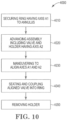
- FIG. 10 is a flow chart illustrating method 4000 according to some embodiments.
- Step 4010 includes securing an abutment ring having a first axis to a patient's annulus.
- Step 4020 includes advancing a removable bioprosthetic heart valve assembly adjacent to the abutment ring, the removable bioprosthetic heart valve assembly comprising a bioprosthetic valve for coupling to the abutment ring and a holder detachably coupled to the bioprosthetic valve.
- the holder having a first surface, a second axis perpendicular to the first surface, and a maneuvering system for aligning the first axis and the second axis.
- Step 4030 includes maneuvering the maneuvering system to align the first axis and the second axis.
- Step 4040 includes seating the bioprosthetic valve by further advancing the removable bioprosthetic heart valve assembly into the abutment ring and coupling the bioprosthetic valve to the abutment ring.
- Heart valve prosthesis 280 for implantation at a heart valve annulus location of a patient's heart is disclosed.
- Heart valve prosthesis 280 comprises: abutment ring 50 configured for attachment at the heart valve annulus location 30, the abutment ring having a first axis A1; and removable bioprosthetic heart valve assembly 250 comprising: bioprosthetic valve 200 configured for coupling to the abutment ring 50; and, holder 100 detachably coupled to the bioprosthetic valve 200.
- Holder 100 includes: first surface 110 and a second axis A2 perpendicular to the first surface; and, and maneuvering system 120 for aligning the first axis and the second axis (A1 and A2).
- the maneuvering system includes: central pin 130 pivotable relative to holder 100 and rotatable with holder 100, wherein the second axis A2 passes through central pin 130; and, a first threadable arcuate bore 140 and a second threadable arcuate bore 150, each bore having first and second openings disposed at first surface 110 and first and second threads (146, 156) therethrough, for tilting the first surface and aligning the first axis and the second axis (A1 and A2).
- the multiple component heart valve prosthesis further comprises a detachable fit joint having a proximal end and a distal end, the proximal end configured for coupling to the holder and the distal end configured for coupling to an elongated handle.
Landscapes
- Health & Medical Sciences (AREA)
- Cardiology (AREA)
- Oral & Maxillofacial Surgery (AREA)
- Transplantation (AREA)
- Engineering & Computer Science (AREA)
- Biomedical Technology (AREA)
- Heart & Thoracic Surgery (AREA)
- Vascular Medicine (AREA)
- Life Sciences & Earth Sciences (AREA)
- Animal Behavior & Ethology (AREA)
- General Health & Medical Sciences (AREA)
- Public Health (AREA)
- Veterinary Medicine (AREA)
- Prostheses (AREA)
Claims (14)
- Implantationszubehör (100, 500, 700, 800) zur Platzierung an einer Herzklappenringstelle des Herzens eines Patienten, wobei der Ring eine erste Achse (A1) aufweist, wobei das Implantationszubehör (100, 500, 700, 800) Folgendes umfasst:eine erste Oberfläche (110, 560, 710);eine zweite Achse (A2), die senkrecht zu der ersten Oberfläche (110, 560, 710) verläuft; und,ein Manövriersystem (120, 520, 720, 820) zum Ausrichten der ersten Achse (A1) und der zweiten Achse (A2),wobei das Manövriersystem (120, 520, 720, 820) eine erste Gewindebohrung (140, 580, 740, 840) und eine zweite Gewindebohrung (150, 585, 750, 845) einschließt, wobei jede Bohrung erste und zweite Öffnungen (142, 144, 152, 154; 742, 744, 752, 754) aufweist, die an der ersten Oberfläche (110, 560, 710) angeordnet sind,wobei die erste Gewindebohrung (140, 580, 740, 840) und die zweite Gewindebohrung (150, 585, 750, 845) ein erstes Gewinde (146, 546, 746) beziehungsweise ein zweites Gewinde (156, 556, 756) dort hindurch einschließen, um die erste Oberfläche (110, 560, 710) zu kippen und die erste Achse (A1) und die zweite Achse (A2) auszurichten,wobei das Manövriersystem (120, 520, 720, 820) einen greifbaren zentralen Stift (130, 530, 730) einschließt, der relativ zu dem Implantationszubehör (100, 500, 700, 800) schwenkbar ist, wobei die zweite Achse (A2) durch den zentralen Stift (130, 530, 730) hindurch verläuft, wobei der zentrale Stift (130, 530, 730) weiter mit dem Implantationszubehör (100, 500, 700, 800) in einer ersten Richtung im Uhrzeigersinn (D1) und in einer zweiten Richtung gegen den Uhrzeigersinn (D2) drehbar ist, und wobei eine Manipulation oder ein Ziehen an dem ersten (146, 546, 746) und dem zweiten (156, 556, 756) Gewinde, während der zentrale Stift (130, 530, 730) ergriffen wird, dazu führt, dass die erste Oberfläche (110, 560, 710) gekippt und die erste Achse (A1) und die zweite Achse (A2) ausgerichtet werden.
- Implantationszubehör (100, 500, 700, 800) nach Anspruch 1, wobei die zweite Achse (A2) orthogonal zu dem zentralen Stift (130, 530, 730) ist.
- Implantationszubehör (100, 500, 700, 800) nach Anspruch 2, wobei der zentrale Stift (130, 530, 730) an einer minimalinvasiven Herz-Thorax-Chirurgie (MICS)-Zange befestigt werden kann.
- Implantationszubehör (100, 500, 700, 800) nach Anspruch 1, wobei das Implantationszubehör so konfiguriert ist, dass es die Größe des Rings bestimmt.
- Implantationszubehör (100, 500, 700, 800) nach Anspruch 1, wobei das Implantationszubehör so konfiguriert ist, dass es eine entfernbare bioprothetische Herzklappenanordnung implantiert.
- Implantationszubehör (100, 500, 700, 800) nach Anspruch 1, wobei das Implantationszubehör (100, 500, 700, 800) so konfiguriert ist, dass es eine entfernbare mechanische Herzklappenanordnung implantiert.
- Implantationszubehör (100, 500, 700, 800) nach Anspruch 6, wobei das Implantationszubehör so konfiguriert ist, dass es eine Vielzahl von Blättern der entfernbaren mechanischen Herzklappenanordnung positioniert.
- Entfernbare bioprothetische Herzklappenanordnung (250, 1300) zur Implantation in einen Auflagering (50, 1050), der an einer Herzklappenringstelle des Herzens eines Patienten befestigt ist, wobei der Auflagering (50, 1050) eine erste Achse (A1) aufweist, wobei die entfernbare bioprothetische Herzklappenanordnung (250, 1300) Folgendes umfasst:eine bioprothetische Klappe (200, 1320) zur Kopplung mit dem Auflagering (50, 1050); und,einen Halter (100, 1310), der abnehmbar mit der bioprothetischen Klappe (200, 1320) gekoppelt ist, wobei der Halter (100, 1310) Folgendes aufweist:eine erste Oberfläche (110);eine zweite Achse (A2), die senkrecht zu der ersten Oberfläche (110) verläuft; und,ein Manövriersystem (120) zum Ausrichten der ersten Achse (A1) und der zweiten Achse (A2),wobei das Manövriersystem (120) eine erste bogenförmige Gewindebohrung (140) und eine zweite bogenförmige Gewindebohrung (150) einschließt, wobei jede Bohrung (140, 150) erste und zweite Öffnungen aufweist, die an der ersten Oberfläche (110) angeordnet sind,wobei die erste bogenförmige Gewindebohrung (140) und die zweite bogenförmige Gewindebohrung (150) ein erstes Gewinde (146, 2146) beziehungsweise ein zweites Gewinde (156, 2156) dort hindurch einschließen, um die erste Oberfläche (110) zu kippen und die erste Achse (A1) und die zweite Achse (A2) auszurichten,wobei das Manövriersystem (120) einen greifbaren zentralen Stift (130) einschließt, der relativ zu dem Halter (100) schwenkbar ist, wobei die zweite Achse (A2) durch den zentralen Stift (130) hindurch verläuft, wobei der zentrale Stift (130) weiter mit dem Halter (100) in einer ersten Richtung im Uhrzeigersinn (D1) und in einer zweiten Richtung gegen den Uhrzeigersinn (D2) drehbar ist, und wobei die Manipulation oder das Ziehen an dem ersten (146) und dem zweiten (156) Gewinde, während der zentrale Stift (130) ergriffen wird, dazu führt, dass die erste Oberfläche (110) gekippt und die erste Achse (A1) und die zweite Achse (A2) ausgerichtet werden.
- Entfernbare bioprothetische Herzklappenanordnung (250, 1300) nach Anspruch 8, wobei die zweite Achse (A2) orthogonal zu dem zentralen Stift (130) verläuft.
- Entfernbare bioprothetische Herzklappenanordnung (250, 1300) nach Anspruch 8, weiter umfassend eine abnehmbare Passverbindung (160), die ein proximales Ende (162) und ein distales Ende (164) aufweist, wobei das proximale Ende (162) zur Kopplung mit dem Halter (100) konfiguriert ist und das distale Ende (164) zur Kopplung mit einem länglichen Griff (300) konfiguriert ist.
- Entfernbare bioprothetische Herzklappenanordnung (1300) nach Anspruch 8, weiter umfassend den Auflagering (1050), wobei der Auflagering (1050) ein Verriegelungssystem (1200) einschließt und die bioprothetische Klappe (1320) mindestens ein Verriegelungsmerkmal einschließt, wobei das mindestens eine Verriegelungsmerkmal so konfiguriert ist, dass es von dem Verriegelungssystem (1200) aufgenommen wird.
- Entfernbare bioprothetische Herzklappenanordnung (1300) nach Anspruch 11, wobei das Verriegelungssystem (1200) mindestens einen Kanal (1240) umfasst, der so konfiguriert ist, dass er das mindestens eine Verriegelungsmerkmal der bioprothetischen Klappe (1320) aufnimmt, so dass der Halter (1310) relativ zu dem Auflagering (1050) in mindestens eine erste Eingriffsposition und eine zweite Außereingriffsposition gedreht werden kann.
- Entfernbare bioprothetische Herzklappenanordnung (1300) nach Anspruch 12, wobei der zentrale Stift (130) mit dem Halter relativ zu dem Auflagering (1050) drehbar ist, um den Halter im Uhrzeigersinn in die Eingriffsposition und gegen den Uhrzeigersinn in die Außereingriffsposition zu drehen.
- Entfernbare bioprothetische Herzklappenanordnung (1300) nach Anspruch 11, wobei der Auflagering (1050) am Mitralklappenrand eines Patienten befestigt werden kann.
Applications Claiming Priority (1)
| Application Number | Priority Date | Filing Date | Title |
|---|---|---|---|
| PCT/IB2018/055890 WO2020030944A1 (en) | 2018-08-06 | 2018-08-06 | Tiltable tools for heart valve prosthesis |
Publications (2)
| Publication Number | Publication Date |
|---|---|
| EP3833305A1 EP3833305A1 (de) | 2021-06-16 |
| EP3833305B1 true EP3833305B1 (de) | 2025-05-28 |
Family
ID=63452690
Family Applications (1)
| Application Number | Title | Priority Date | Filing Date |
|---|---|---|---|
| EP18762926.6A Active EP3833305B1 (de) | 2018-08-06 | 2018-08-06 | Kippbare werkzeuge für herzklappenprothese |
Country Status (7)
| Country | Link |
|---|---|
| US (1) | US12059347B2 (de) |
| EP (1) | EP3833305B1 (de) |
| JP (1) | JP7146064B2 (de) |
| CN (1) | CN112702975B (de) |
| AU (1) | AU2018435607A1 (de) |
| CA (1) | CA3107874A1 (de) |
| WO (1) | WO2020030944A1 (de) |
Family Cites Families (18)
| Publication number | Priority date | Publication date | Assignee | Title |
|---|---|---|---|---|
| US4865600A (en) * | 1981-08-25 | 1989-09-12 | Baxter International Inc. | Mitral valve holder |
| US4473077A (en) | 1982-05-28 | 1984-09-25 | United States Surgical Corporation | Surgical stapler apparatus with flexible shaft |
| US5972030A (en) * | 1993-02-22 | 1999-10-26 | Heartport, Inc. | Less-invasive devices and methods for treatment of cardiac valves |
| US5735842A (en) * | 1995-09-11 | 1998-04-07 | St. Jude Medical, Inc. | Low profile manipulators for heart valve prostheses |
| US5788689A (en) * | 1996-01-31 | 1998-08-04 | St. Jude Medical, Inc. | Prosthetic heart valve rotator tool |
| JP3881748B2 (ja) * | 1997-05-22 | 2007-02-14 | 有限会社安久工機 | 僧帽弁用オブチュレータ |
| US6176877B1 (en) | 1998-04-20 | 2001-01-23 | St. Jude Medical, Inc. | Two piece prosthetic heart valve |
| US6409758B2 (en) * | 2000-07-27 | 2002-06-25 | Edwards Lifesciences Corporation | Heart valve holder for constricting the valve commissures and methods of use |
| JP2004154164A (ja) | 2002-11-01 | 2004-06-03 | Mizuho Co Ltd | 多自由度型処置具 |
| CA2698388C (en) * | 2007-09-07 | 2015-11-24 | Edwards Lifesciences Corporation | Active holder for annuloplasty ring delivery |
| FR2943906B1 (fr) | 2009-04-03 | 2013-03-22 | Univ Pierre Et Marie Curie Paris 6 | Instrument chirurgical. |
| US9078750B2 (en) | 2010-11-30 | 2015-07-14 | Edwards Lifesciences Corporation | Ergonomic mitral heart valve holders |
| DE202011000848U1 (de) | 2011-04-12 | 2011-06-09 | Aesculap AG, 78532 | Steuerungsvorrichtung |
| EP2520250B1 (de) * | 2011-05-04 | 2014-02-19 | Medtentia International Ltd Oy | Medizinische Vorrichtung für ein Herzklappenimplantat |
| US9987000B2 (en) | 2014-12-18 | 2018-06-05 | Ethicon Llc | Surgical instrument assembly comprising a flexible articulation system |
| US10085756B2 (en) | 2015-07-24 | 2018-10-02 | Covidien Lp | Anvil assembly and anvil assembly delivery system |
| WO2017216607A1 (en) * | 2016-06-15 | 2017-12-21 | Sorin Group Italia S.R.L | Two-part mitral valve and implant method |
| US10722356B2 (en) * | 2016-11-03 | 2020-07-28 | Edwards Lifesciences Corporation | Prosthetic mitral valve holders |
-
2018
- 2018-08-06 CA CA3107874A patent/CA3107874A1/en active Pending
- 2018-08-06 CN CN201880097559.7A patent/CN112702975B/zh active Active
- 2018-08-06 JP JP2021506441A patent/JP7146064B2/ja active Active
- 2018-08-06 US US17/254,179 patent/US12059347B2/en active Active
- 2018-08-06 AU AU2018435607A patent/AU2018435607A1/en not_active Abandoned
- 2018-08-06 WO PCT/IB2018/055890 patent/WO2020030944A1/en not_active Ceased
- 2018-08-06 EP EP18762926.6A patent/EP3833305B1/de active Active
Also Published As
| Publication number | Publication date |
|---|---|
| US12059347B2 (en) | 2024-08-13 |
| EP3833305A1 (de) | 2021-06-16 |
| US20210259834A1 (en) | 2021-08-26 |
| WO2020030944A1 (en) | 2020-02-13 |
| AU2018435607A1 (en) | 2021-02-18 |
| CN112702975A (zh) | 2021-04-23 |
| CN112702975B (zh) | 2024-03-05 |
| CA3107874A1 (en) | 2020-02-13 |
| JP2021532932A (ja) | 2021-12-02 |
| JP7146064B2 (ja) | 2022-10-03 |
Similar Documents
| Publication | Publication Date | Title |
|---|---|---|
| US8398707B2 (en) | Heart valve holder for use in valve implantation procedures | |
| US6319280B1 (en) | Prosthetic ring holder | |
| US5403305A (en) | Mitral valve prosthesis rotator | |
| CN101222884B (zh) | 用来放置瓣环成形术环的设备和系统 | |
| EP0852481B1 (de) | Herzklappenhalter für eine herzklappenprothese | |
| US5843177A (en) | Apparatus for attaching a handle to an annuloplasty ring implantation device | |
| US8454684B2 (en) | Heart valve holder for use in valve implantation procedures | |
| EP0955895B1 (de) | Vorrichtung zum einer herzklappen-haltevorrichtung an eine herzklappen-prothese | |
| US9326850B2 (en) | Sutureless prosthetic device | |
| CN112969431B (zh) | 具有可拆卸手柄的瓣环成形环组合件 | |
| EP3833305B1 (de) | Kippbare werkzeuge für herzklappenprothese | |
| CN119235506A (zh) | 一种假体系统及输送装置 | |
| US12029651B2 (en) | Implant holder assembly with actuator for heart valve repair and replacement | |
| KR20210087047A (ko) | 가요성 샤프트를 갖는 링 홀더를 포함하는 판륜 성형 링 조립체 | |
| WO2024147747A1 (ru) | Протез клапана сердца |
Legal Events
| Date | Code | Title | Description |
|---|---|---|---|
| STAA | Information on the status of an ep patent application or granted ep patent |
Free format text: STATUS: UNKNOWN |
|
| STAA | Information on the status of an ep patent application or granted ep patent |
Free format text: STATUS: THE INTERNATIONAL PUBLICATION HAS BEEN MADE |
|
| PUAI | Public reference made under article 153(3) epc to a published international application that has entered the european phase |
Free format text: ORIGINAL CODE: 0009012 |
|
| STAA | Information on the status of an ep patent application or granted ep patent |
Free format text: STATUS: REQUEST FOR EXAMINATION WAS MADE |
|
| 17P | Request for examination filed |
Effective date: 20201117 |
|
| AK | Designated contracting states |
Kind code of ref document: A1 Designated state(s): AL AT BE BG CH CY CZ DE DK EE ES FI FR GB GR HR HU IE IS IT LI LT LU LV MC MK MT NL NO PL PT RO RS SE SI SK SM TR |
|
| RAP1 | Party data changed (applicant data changed or rights of an application transferred) |
Owner name: CORCYM S.R.L. |
|
| DAV | Request for validation of the european patent (deleted) | ||
| DAX | Request for extension of the european patent (deleted) | ||
| STAA | Information on the status of an ep patent application or granted ep patent |
Free format text: STATUS: EXAMINATION IS IN PROGRESS |
|
| 17Q | First examination report despatched |
Effective date: 20221216 |
|
| RAP3 | Party data changed (applicant data changed or rights of an application transferred) |
Owner name: CORCYM S.R.L. |
|
| 111Z | Information provided on other rights and legal means of execution |
Free format text: AL AT BE BG CH CY CZ DE DK EE ES FI FR GB GR HR HU IE IS IT LT LU LV MC MK MT NL NO PL PT RO RS SE SI SK SM TR Effective date: 20221021 |
|
| P01 | Opt-out of the competence of the unified patent court (upc) registered |
Effective date: 20230529 |
|
| GRAP | Despatch of communication of intention to grant a patent |
Free format text: ORIGINAL CODE: EPIDOSNIGR1 |
|
| STAA | Information on the status of an ep patent application or granted ep patent |
Free format text: STATUS: GRANT OF PATENT IS INTENDED |
|
| INTG | Intention to grant announced |
Effective date: 20250306 |
|
| GRAS | Grant fee paid |
Free format text: ORIGINAL CODE: EPIDOSNIGR3 |
|
| GRAA | (expected) grant |
Free format text: ORIGINAL CODE: 0009210 |
|
| STAA | Information on the status of an ep patent application or granted ep patent |
Free format text: STATUS: THE PATENT HAS BEEN GRANTED |
|
| AK | Designated contracting states |
Kind code of ref document: B1 Designated state(s): AL AT BE BG CH CY CZ DE DK EE ES FI FR GB GR HR HU IE IS IT LI LT LU LV MC MK MT NL NO PL PT RO RS SE SI SK SM TR |
|
| REG | Reference to a national code |
Ref country code: GB Ref legal event code: FG4D |
|
| REG | Reference to a national code |
Ref country code: CH Ref legal event code: EP |
|
| REG | Reference to a national code |
Ref country code: IE Ref legal event code: FG4D Ref country code: DE Ref legal event code: R096 Ref document number: 602018082279 Country of ref document: DE |
|
| REG | Reference to a national code |
Ref country code: NL Ref legal event code: MP Effective date: 20250528 |
|
| PG25 | Lapsed in a contracting state [announced via postgrant information from national office to epo] |
Ref country code: ES Free format text: LAPSE BECAUSE OF FAILURE TO SUBMIT A TRANSLATION OF THE DESCRIPTION OR TO PAY THE FEE WITHIN THE PRESCRIBED TIME-LIMIT Effective date: 20250528 Ref country code: FI Free format text: LAPSE BECAUSE OF FAILURE TO SUBMIT A TRANSLATION OF THE DESCRIPTION OR TO PAY THE FEE WITHIN THE PRESCRIBED TIME-LIMIT Effective date: 20250528 |
|
| PGFP | Annual fee paid to national office [announced via postgrant information from national office to epo] |
Ref country code: DE Payment date: 20250819 Year of fee payment: 8 |
|
| REG | Reference to a national code |
Ref country code: LT Ref legal event code: MG9D |
|
| PG25 | Lapsed in a contracting state [announced via postgrant information from national office to epo] |
Ref country code: NO Free format text: LAPSE BECAUSE OF FAILURE TO SUBMIT A TRANSLATION OF THE DESCRIPTION OR TO PAY THE FEE WITHIN THE PRESCRIBED TIME-LIMIT Effective date: 20250828 Ref country code: GR Free format text: LAPSE BECAUSE OF FAILURE TO SUBMIT A TRANSLATION OF THE DESCRIPTION OR TO PAY THE FEE WITHIN THE PRESCRIBED TIME-LIMIT Effective date: 20250829 |
|
| PG25 | Lapsed in a contracting state [announced via postgrant information from national office to epo] |
Ref country code: PL Free format text: LAPSE BECAUSE OF FAILURE TO SUBMIT A TRANSLATION OF THE DESCRIPTION OR TO PAY THE FEE WITHIN THE PRESCRIBED TIME-LIMIT Effective date: 20250528 Ref country code: NL Free format text: LAPSE BECAUSE OF FAILURE TO SUBMIT A TRANSLATION OF THE DESCRIPTION OR TO PAY THE FEE WITHIN THE PRESCRIBED TIME-LIMIT Effective date: 20250528 |
|
| PGFP | Annual fee paid to national office [announced via postgrant information from national office to epo] |
Ref country code: IT Payment date: 20250818 Year of fee payment: 8 |
|
| PG25 | Lapsed in a contracting state [announced via postgrant information from national office to epo] |
Ref country code: BG Free format text: LAPSE BECAUSE OF FAILURE TO SUBMIT A TRANSLATION OF THE DESCRIPTION OR TO PAY THE FEE WITHIN THE PRESCRIBED TIME-LIMIT Effective date: 20250528 |
|
| PGFP | Annual fee paid to national office [announced via postgrant information from national office to epo] |
Ref country code: GB Payment date: 20250827 Year of fee payment: 8 |
|
| PG25 | Lapsed in a contracting state [announced via postgrant information from national office to epo] |
Ref country code: HR Free format text: LAPSE BECAUSE OF FAILURE TO SUBMIT A TRANSLATION OF THE DESCRIPTION OR TO PAY THE FEE WITHIN THE PRESCRIBED TIME-LIMIT Effective date: 20250528 |
|
| PGFP | Annual fee paid to national office [announced via postgrant information from national office to epo] |
Ref country code: FR Payment date: 20250820 Year of fee payment: 8 |
|
| PG25 | Lapsed in a contracting state [announced via postgrant information from national office to epo] |
Ref country code: RS Free format text: LAPSE BECAUSE OF FAILURE TO SUBMIT A TRANSLATION OF THE DESCRIPTION OR TO PAY THE FEE WITHIN THE PRESCRIBED TIME-LIMIT Effective date: 20250828 |
|
| PG25 | Lapsed in a contracting state [announced via postgrant information from national office to epo] |
Ref country code: IS Free format text: LAPSE BECAUSE OF FAILURE TO SUBMIT A TRANSLATION OF THE DESCRIPTION OR TO PAY THE FEE WITHIN THE PRESCRIBED TIME-LIMIT Effective date: 20250928 |
|
| PG25 | Lapsed in a contracting state [announced via postgrant information from national office to epo] |
Ref country code: LV Free format text: LAPSE BECAUSE OF FAILURE TO SUBMIT A TRANSLATION OF THE DESCRIPTION OR TO PAY THE FEE WITHIN THE PRESCRIBED TIME-LIMIT Effective date: 20250528 |
|
| REG | Reference to a national code |
Ref country code: AT Ref legal event code: MK05 Ref document number: 1798211 Country of ref document: AT Kind code of ref document: T Effective date: 20250528 |
|
| PG25 | Lapsed in a contracting state [announced via postgrant information from national office to epo] |
Ref country code: SM Free format text: LAPSE BECAUSE OF FAILURE TO SUBMIT A TRANSLATION OF THE DESCRIPTION OR TO PAY THE FEE WITHIN THE PRESCRIBED TIME-LIMIT Effective date: 20250528 Ref country code: DK Free format text: LAPSE BECAUSE OF FAILURE TO SUBMIT A TRANSLATION OF THE DESCRIPTION OR TO PAY THE FEE WITHIN THE PRESCRIBED TIME-LIMIT Effective date: 20250528 Ref country code: AT Free format text: LAPSE BECAUSE OF FAILURE TO SUBMIT A TRANSLATION OF THE DESCRIPTION OR TO PAY THE FEE WITHIN THE PRESCRIBED TIME-LIMIT Effective date: 20250528 |
|
| PG25 | Lapsed in a contracting state [announced via postgrant information from national office to epo] |
Ref country code: CZ Free format text: LAPSE BECAUSE OF FAILURE TO SUBMIT A TRANSLATION OF THE DESCRIPTION OR TO PAY THE FEE WITHIN THE PRESCRIBED TIME-LIMIT Effective date: 20250528 |
|
| PG25 | Lapsed in a contracting state [announced via postgrant information from national office to epo] |
Ref country code: EE Free format text: LAPSE BECAUSE OF FAILURE TO SUBMIT A TRANSLATION OF THE DESCRIPTION OR TO PAY THE FEE WITHIN THE PRESCRIBED TIME-LIMIT Effective date: 20250528 |
|
| PG25 | Lapsed in a contracting state [announced via postgrant information from national office to epo] |
Ref country code: SK Free format text: LAPSE BECAUSE OF FAILURE TO SUBMIT A TRANSLATION OF THE DESCRIPTION OR TO PAY THE FEE WITHIN THE PRESCRIBED TIME-LIMIT Effective date: 20250528 Ref country code: RO Free format text: LAPSE BECAUSE OF FAILURE TO SUBMIT A TRANSLATION OF THE DESCRIPTION OR TO PAY THE FEE WITHIN THE PRESCRIBED TIME-LIMIT Effective date: 20250528 |
|
| REG | Reference to a national code |
Ref country code: DE Ref legal event code: R097 Ref document number: 602018082279 Country of ref document: DE |
|
| REG | Reference to a national code |
Ref country code: CH Ref legal event code: H13 Free format text: ST27 STATUS EVENT CODE: U-0-0-H10-H13 (AS PROVIDED BY THE NATIONAL OFFICE) Effective date: 20260324 |
|
| PG25 | Lapsed in a contracting state [announced via postgrant information from national office to epo] |
Ref country code: MC Free format text: LAPSE BECAUSE OF FAILURE TO SUBMIT A TRANSLATION OF THE DESCRIPTION OR TO PAY THE FEE WITHIN THE PRESCRIBED TIME-LIMIT Effective date: 20250528 |
|
| PLBE | No opposition filed within time limit |
Free format text: ORIGINAL CODE: 0009261 |
|
| STAA | Information on the status of an ep patent application or granted ep patent |
Free format text: STATUS: NO OPPOSITION FILED WITHIN TIME LIMIT |
|
| REG | Reference to a national code |
Ref country code: CH Ref legal event code: L10 Free format text: ST27 STATUS EVENT CODE: U-0-0-L10-L00 (AS PROVIDED BY THE NATIONAL OFFICE) Effective date: 20260409 |
|
| PG25 | Lapsed in a contracting state [announced via postgrant information from national office to epo] |
Ref country code: LU Free format text: LAPSE BECAUSE OF NON-PAYMENT OF DUE FEES Effective date: 20250806 |