EP3833526B1 - Vorrichtung zum zuführen von vorformlingen mit führungselementen mit variabler position - Google Patents
Vorrichtung zum zuführen von vorformlingen mit führungselementen mit variabler position Download PDFInfo
- Publication number
- EP3833526B1 EP3833526B1 EP19761916.6A EP19761916A EP3833526B1 EP 3833526 B1 EP3833526 B1 EP 3833526B1 EP 19761916 A EP19761916 A EP 19761916A EP 3833526 B1 EP3833526 B1 EP 3833526B1
- Authority
- EP
- European Patent Office
- Prior art keywords
- guide
- preforms
- neck
- adjustable
- frame
- Prior art date
- Legal status (The legal status is an assumption and is not a legal conclusion. Google has not performed a legal analysis and makes no representation as to the accuracy of the status listed.)
- Active
Links
Images




Classifications
-
- B—PERFORMING OPERATIONS; TRANSPORTING
- B29—WORKING OF PLASTICS; WORKING OF SUBSTANCES IN A PLASTIC STATE IN GENERAL
- B29C—SHAPING OR JOINING OF PLASTICS; SHAPING OF MATERIAL IN A PLASTIC STATE, NOT OTHERWISE PROVIDED FOR; AFTER-TREATMENT OF THE SHAPED PRODUCTS, e.g. REPAIRING
- B29C49/00—Blow-moulding, i.e. blowing a preform or parison to a desired shape within a mould; Apparatus therefor
- B29C49/42—Component parts, details or accessories; Auxiliary operations
- B29C49/4205—Handling means, e.g. transfer, loading or discharging means
- B29C49/42093—Transporting apparatus, e.g. slides, wheels or conveyors
- B29C49/42097—Sliding rails, e.g. inclined
-
- B—PERFORMING OPERATIONS; TRANSPORTING
- B65—CONVEYING; PACKING; STORING; HANDLING THIN OR FILAMENTARY MATERIAL
- B65G—TRANSPORT OR STORAGE DEVICES, e.g. CONVEYORS FOR LOADING OR TIPPING, SHOP CONVEYOR SYSTEMS OR PNEUMATIC TUBE CONVEYORS
- B65G17/00—Conveyors having an endless traction element, e.g. a chain, transmitting movement to a continuous or substantially-continuous load-carrying surface or to a series of individual load-carriers; Endless-chain conveyors in which the chains form the load-carrying surface
- B65G17/12—Conveyors having an endless traction element, e.g. a chain, transmitting movement to a continuous or substantially-continuous load-carrying surface or to a series of individual load-carriers; Endless-chain conveyors in which the chains form the load-carrying surface comprising a series of individual load-carriers fixed, or normally fixed, relative to traction element
-
- B—PERFORMING OPERATIONS; TRANSPORTING
- B29—WORKING OF PLASTICS; WORKING OF SUBSTANCES IN A PLASTIC STATE IN GENERAL
- B29C—SHAPING OR JOINING OF PLASTICS; SHAPING OF MATERIAL IN A PLASTIC STATE, NOT OTHERWISE PROVIDED FOR; AFTER-TREATMENT OF THE SHAPED PRODUCTS, e.g. REPAIRING
- B29C2949/00—Indexing scheme relating to blow-moulding
- B29C2949/07—Preforms or parisons characterised by their configuration
- B29C2949/0715—Preforms or parisons characterised by their configuration the preform having one end closed
-
- B—PERFORMING OPERATIONS; TRANSPORTING
- B29—WORKING OF PLASTICS; WORKING OF SUBSTANCES IN A PLASTIC STATE IN GENERAL
- B29C—SHAPING OR JOINING OF PLASTICS; SHAPING OF MATERIAL IN A PLASTIC STATE, NOT OTHERWISE PROVIDED FOR; AFTER-TREATMENT OF THE SHAPED PRODUCTS, e.g. REPAIRING
- B29C49/00—Blow-moulding, i.e. blowing a preform or parison to a desired shape within a mould; Apparatus therefor
- B29C49/02—Combined blow-moulding and manufacture of the preform or the parison
- B29C49/06—Injection blow-moulding
-
- B—PERFORMING OPERATIONS; TRANSPORTING
- B29—WORKING OF PLASTICS; WORKING OF SUBSTANCES IN A PLASTIC STATE IN GENERAL
- B29C—SHAPING OR JOINING OF PLASTICS; SHAPING OF MATERIAL IN A PLASTIC STATE, NOT OTHERWISE PROVIDED FOR; AFTER-TREATMENT OF THE SHAPED PRODUCTS, e.g. REPAIRING
- B29C49/00—Blow-moulding, i.e. blowing a preform or parison to a desired shape within a mould; Apparatus therefor
- B29C49/42—Component parts, details or accessories; Auxiliary operations
- B29C49/4205—Handling means, e.g. transfer, loading or discharging means
- B29C49/42051—Means for stripping, aligning or de-stacking
- B29C49/42057—Aligning disorderly arranged preforms, e.g. delivered disorderly
-
- B—PERFORMING OPERATIONS; TRANSPORTING
- B29—WORKING OF PLASTICS; WORKING OF SUBSTANCES IN A PLASTIC STATE IN GENERAL
- B29K—INDEXING SCHEME ASSOCIATED WITH SUBCLASSES B29B, B29C OR B29D, RELATING TO MOULDING MATERIALS OR TO MATERIALS FOR MOULDS, REINFORCEMENTS, FILLERS OR PREFORMED PARTS, e.g. INSERTS
- B29K2067/00—Use of polyesters or derivatives thereof, as moulding material
- B29K2067/003—PET, i.e. poylethylene terephthalate
-
- B—PERFORMING OPERATIONS; TRANSPORTING
- B29—WORKING OF PLASTICS; WORKING OF SUBSTANCES IN A PLASTIC STATE IN GENERAL
- B29L—INDEXING SCHEME ASSOCIATED WITH SUBCLASS B29C, RELATING TO PARTICULAR ARTICLES
- B29L2031/00—Other particular articles
- B29L2031/712—Containers; Packaging elements or accessories, Packages
-
- B—PERFORMING OPERATIONS; TRANSPORTING
- B29—WORKING OF PLASTICS; WORKING OF SUBSTANCES IN A PLASTIC STATE IN GENERAL
- B29L—INDEXING SCHEME ASSOCIATED WITH SUBCLASS B29C, RELATING TO PARTICULAR ARTICLES
- B29L2031/00—Other particular articles
- B29L2031/712—Containers; Packaging elements or accessories, Packages
- B29L2031/7158—Bottles
Definitions
- the feed device is intended to be implemented in an installation for blow molding containers made of thermoplastic material, such as polyethylene terephthalate (PET).
- thermoplastic material such as polyethylene terephthalate (PET).
- such containers are produced in two main steps.
- a first step one proceeds to the injection molding of a preform in thermoplastic material.
- This preform comprises a substantially tubular body which is closed at one of its axial ends. Its other end has, from this injection molding operation, the final shape of the neck of the container.
- the neck of the container has a thread and, at its base, an annular support collar which extends radially projecting outwards with respect to the neck and with respect to the neck.
- the preforms are manufactured by injection in a first place and are molded by blow molding to the final shape of the container in a second place on a specific blow molding machine.
- Such technology makes it possible to carry out the blow molding operation as close as possible to the place of bottling, the injection operation being able to be carried out at any place.
- it is relatively easy and inexpensive to transport preforms, while transporting containers after blow molding has the disadvantage of being economically unprofitable due to the very large volume of the containers.
- the blow molding machine has a preform feeding device which is equipped with a system for disentangling and aligning the preforms.
- the preforms are dumped in bulk into a bin. They are taken from this tray by an elevator belt which, in turn, unloads the preforms, according to a pre-established rhythm, at the upper end of orienting rollers, also called alignment rollers.
- orienting rollers also called alignment rollers.
- These two alignment rollers are inclined with respect to the horizontal and they are substantially parallel to each other.
- the two rollers are driven in rotation in opposite directions, and are separated from each other so as to leave an interval which is of a dimension slightly greater than the dimension of the bodies of the preforms, but of a dimension less than the external diameter of the support collar located at the base of the neck.
- the orienting rollers are configured in such a way that, under the effect of gravity, the preforms are forced between the two rollers.
- each preform tends to stand between the two rollers, so as to be suspended by its collar between the rollers.
- the counter rotational movement of the two rollers ensures the placement of the preforms upright one behind the other, and the inclination of the rollers ensures the sliding of the preforms along the axis of the rollers, towards the bottom of the orienting rollers where they are next recovered in a sliding slide itself connected to the blowing installation.
- the slideway for moving the preforms comprises a longitudinal slot which is delimited transversely by two parallel rails.
- each preform tends to stand upright in the slide, between the two parallel rails, so as to be suspended by its collar on the rails.
- the scroll slide is configured so that only perfectly positioned preforms are allowed to slide down.
- the rails of the slide have numerous guide elements which make it possible to ensure that only the well-positioned preforms can pass.
- these guide elements make it possible to guarantee that the preforms received in the slide maintain a correct position until they arrive at the bottom of the slide.
- Container manufacturing facilities are designed to be able to receive preforms of different formats.
- the guide elements are mounted adjustable in position on the slide. During a change of preform format, numerous adjustments must be made, in particular to make it possible to adjust the guide elements to the dimensions of the new preform model.
- US 2015101909A1 discloses a system for adjusting at least the vertical adjustment between a first transport device and a second transport device in a transport section for preforms for plastic containers.
- the longitudinal, vertical and transverse orientations indicated by the trihedron "L, V, T" of the figures will be adopted without limitation.
- the vertical direction is used here as a geometric reference oriented perpendicular to the longitudinal axis of the slider.
- the direction of gravity is indicated by the arrow "G" on the figure 1 .
- the slide being inclined at a determined angle with respect to a horizontal plane, the vertical direction is here inclined at the same angle with respect to the direction of gravity.
- inside will be used to qualify a face or a movement directed transversely towards the central slot 27 of the sliding slide 16, while the term “outside” will qualify an opposite direction.
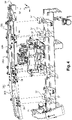
- FIG. 1 very schematically a device 10 for supplying preforms intended for example to supply preforms 18 to a blow molding installation 12 .
- the feed device 10 comprises upper orienting rollers 14 between which preforms 18 are discharged in bulk at a rate determined by means not shown.
- the preforms 18 are oriented neck up and are lined up in a line so as to then be delivered to a sliding slide 16 which transports the preforms 18 to the installation 12 for blowing.
- a sliding slide 16 which transports the preforms 18 to the installation 12 for blowing.
- An example of such orienting rollers 14 is described in detail in the document EP-A1-1.335.870 . Preforms 18 are thus received in the sliding slide 16
- the orienting rollers 14 have a predetermined inclination slope "a", for example 12° relative to the horizontal, to allow the preforms 18 to slide as far as the entrance to the scrolling slide 16 located below the effect of gravity, while the sliding slide 16 has a slope " ⁇ " of greater inclination, for example 15°.
- each preform 18 supplying the blow molding installation 12 has a tubular body 20 with axis “A” which is closed at its lower end.
- the body 20 is open axially upwards via a cylindrical neck 22 which extends the body 20 upwards.
- the neck 22 has, at its junction with the body 20, a flange 24 which extends radially projecting with respect to the cylindrical section of the neck 22 and with respect to the body 20.
- the flange 24 has an annular lower face 25 which has a free outer edge of outer diameter "D1".
- An internal edge of the lower face 25 at the intersection with the body 20 has an internal diameter, hereinafter called diameter "D2" under the neck.
- the body 20 further has, at a distance below the flange 24, a diameter "D3".
- the neck 22 has a determined axial height "H”.
- the invention relates to the slide 16 for running the preforms 18.
- the sliding slide 16 comprises a frame 26 fixed relative to the ground.
- the sliding slide 16 has a longitudinal slot 27 which extends from an entrance 30 to an exit 32 of slide 16 of scrolling.
- the outlet 32 of the sliding slide 16 is located below the inlet 30 to allow the preforms 18 to slide towards the outlet 32 under the effect of gravity.
- the slot 27 is delimited transversely by two sliding paths 34 intended to support the preform 18 upright by its collar 24.
- the preform 18 is more particularly suspended between the two sliding paths 34 by its collar 24.
- the scrolling slide 16 also comprises elements for guiding the preforms 18.
- the guiding elements are here formed by at least one guide 40 under the neck and/or at least one guide 52 body and/or at least one neck guide 62 and/or at least one drinking guide 72.
- These guide elements are mounted adjustable in position on the frame 26 by adjustable fixing means to be adapted to different formats of preform 18. It is indeed important that the guide elements are adjusted as close as possible to the preforms 18 to guarantee that the preforms 18 occupy a position that is perfectly suited to supplying the blow molding installation 12 to the outlet 32 of the slide 16 and to guarantee that the preforms 18 do not jam in the slide 16 during their travel.
- the invention proposes to equip the sliding slide 16 with support plates 36 which are fixed in a reference position on associated reference locations 37 of the frame 26. This means that the position of the support plates 36 is not adjustable with respect to the frame 26. Thus, it is ensured that each support plate 36 occupies said reference position when it is reassembled on the frame 26 after having been dismantled.
- Each preform guide element 18 is adjustable mounted on the frame 26 via at least one associated support plate 36 .
- Each support plate 36 is thus intended to support at least one preform guide element 18.
- Each guide element is fixed in an adjustable position relative to the support plate 36 by associated adjustable fixing means.
- each support plate 36 is also fixed to the frame 26 by means of quick fasteners 82.
- These quick release fasteners 82 are also known by their English name “quick release fastener” or even “snap lock”. Such a quick coupler 82 allows mounting and dismounting of the support plates 36 with a saving of movement and without the use of tools.
- the guide elements being fixed in an adjustable manner on the frame 26 by means of the support plates 36, the guide elements can be removed from the frame 26 by rapid dismantling of the support plates 36 while retaining their adjustment in position relative to the support plates 36 for a specific preform model 18.
- the guide elements and their support plate 36 can again be mounted on the frame 26 with the appropriate adjustment without requiring a new adjustment operation.
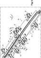
- the sliding slide 16 comprises two groups of guide elements.
- a first group of guide elements is formed by two parallel guide rails 38 which extend longitudinally on either side of the slot 27.
- each guide rail 38 comprises a first guide element formed by a guide 40 under the neck.
- the guide 40 under the neck is in the form of a horizontal plate.
- the guide 40 under the neck comprises the sliding path 34 which is formed on an interior longitudinal edge of an upper face 42 of the guide 40 under the neck.
- the sliding path 34 is intended to support the preforms 18 by their flange 24.
- the guide 40 under the neck is mounted adjustable transversely on associated support plates 36 via first adjustable fixing means.
- the guide 40 under the neck of each guide rail 38 is here divided into two or three independent sections to facilitate the replacement of the guide rails 38.
- the two longitudinal ends of each guide section 40 under the neck are each fixed in an adjustable manner to an associated support plate 36 .
- each guide 40 under the neck is more particularly mounted to slide transversely on the associated support plates 36 by means of vertical axis clamping screws 44 which are received in longitudinal oblong slots 46 of the guide 40 under the neck.
- a free end of the clamping screws 44 is received in a complementary thread of the plate 36 of support.
- the support plate 36 comprises a transverse axis adjustment screw 48 with a captive head which is only capable of rotate around its axis relative to the support plate 36, as is visible in the figure 5 and 6 .
- a threaded rod of the adjustment screw 48 is received in an adjustment nut 50 which is integral in transverse movement with the guide 40 under the neck.
- adjustment nut 50 is here mounted adjustable in the vertical position relative to the guide 40 under the neck to allow adjustment of the trim and the altitude of the guide 40 under the neck relative to the plate 36 of support.
- each guide rail 38 also comprises a second guide element formed by a body guide 52 which is arranged under the guide 40 under the associated neck.
- This body guide 52 is intended to prevent the body 20 of the preforms 18 from swinging transversely between the guide rails 38.
- each body guide 52 has a vertical longitudinal guide panel 54 which extends vertically downward from an underside of the guide 40 under the neck and a horizontal fixing tab 56 which extends transversely outward from an edge of upper end of the guide panel 54.
- the second adjustable fastening means are formed by clamping screws 58 with a vertical axis which are received in an oblong slot 60 extending transversely from the guide 40 under the neck.
- a threaded end of the clamping screw 58 is received in an associated thread of the lug 56 for fixing the guide 52 body, while a head of the clamping screw extends above the guide 40 under the neck.
- the clamping screws 58 are tightened to allow the guide 52 body to be locked in the adjusted position relative to the guide 40 under the neck by tightening between the head of the clamping screw 58 and the lug 56 for fixing the guide 52 body.
- Each body guide 52 is also divided into two or three sections, each of which is associated with a guide section 40 under the neck.
- Each guide rail 38 also comprises a third guide element formed by a neck guide 62 which is arranged on the guide 40 under the neck.
- the neck guides 62 have the function of transversely delimiting the outward sliding path 34 . This makes it possible in particular to prevent the preforms 18 from moving transversely in the slot 27 during their travel.
- the neck guide 62 is here in the form of a bracket comprising a longitudinal vertical guide wing 64 which extends vertically upwards from the sliding path 34, and a lower horizontal fixing wing 66 which extends transversely outward from the lower edge of the guide wing 64.
- the neck guide 62 is mounted adjustable transversely on the under-neck guide 40 via third adjustable fixing means.
- third adjustable fastening means are formed by clamping screws 68 with a vertical axis which are received in an oblong slot 70 of the wing 66 for fastening the guide 62 neck.
- a threaded end of the clamping screw 68 is received in an associated thread of the guide 40 under the neck, while a head of the clamping screw 68 extends above the wing 66 for fixing the guide 62 neck.
- the clamping screws 68 are tightened to allow the guide 62 to be locked in the adjusted position relative to the guide 40 under the collar by tightening the wing 66 for fixing the guide 62 between the head of the clamping screw 68 and the guide 40 under the neck.
- Each neck guide 62 is also divided into two or three sections, each of which is associated with a guide section 40 under the neck.
- one of the guide rails 38 is thus formed of two independent sections 38A, 38B while the other guide rail 38 is formed of three independent sections 38C, 38D, 38E.
- Each section 38A to 38E is carried by two associated support plates 36 arranged at its longitudinal ends. This makes it possible to simplify the handling of the support elements during a change of preform 18 as will be explained later.
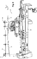
- a second group of guide elements is formed by at least one guide 72 drinking.
- the drinking guide 72 is formed by a transverse longitudinal guide plate which is arranged in line with the sliding slide 16 to hold the necks 22 of the preforms 18 upright in the sliding slide 16.
- the drinking guide 72 is mounted vertically adjustable in position on the frame 26 by means of fourth adjustable fixing means.
- the drinking guide 72 is mounted on the frame 26 by means of an associated support plate 36 to make it possible to detach the drinking guide 72 from the frame 26 by rapid dismantling of the support plate 36 while retaining its adjustment in position by relative to the support plates 36.
- the support plate 36 is formed by a vertical longitudinal plate which is arranged at a distance above the guide rails 38.
- the support plate 36 here rests on reference locations 37 arranged in height relative to the reference locations 37 of the support plates 36 of the guide rail 38.
- the drinking guide 72 is vertically adjustable mounted between the support plate 36 and the guide rails 38 by means of suspension rods 74 which are received in orifices 76 of the support plate 36.
- a lower end of the suspension rods 74 is fixed to the drinking guide 72 while an upper end of the suspension rods 74 projecting above the support plate 36 is provided with a nut 78 which makes it possible to adjust the height of the guide 72 drinking.
- a counter-nut 80 located just below the support plate 36 makes it possible to immobilize the drinking guide 72 vertically with respect to the support plate 36 by tightening when the drinking guide 72 is adjusted in position.
- the guide 72 drinking is adjustable in the longitudinal position relative to the plate 36 support.
- the orifices 76 of the support plate 36 have a longitudinally elongated shape to allow the guide 72 to be guided in longitudinal sliding with respect to the support plate 36.
- Each support plate 36 of a guide rail section 38 here comprises a single quick fastener 82, while the support plate 36 of the drinking guide 72 here has two quick fasteners 82 each arranged at a longitudinal end of the plate 36 of support.
- the quick fasteners 82 are formed by axial interlocking means provided with a ball-locking mechanism.
- the quick couplers 82 comprise a first part which is carried by the support plate 36 and a second part which is carried by the frame 26.
- the first part of the quick coupler 82 comprises a sleeve 84 of vertical axis "B" which forms a female interlocking element.
- the sleeve 84 is fixed on an upper face 86 of the plate 36 of support.
- the sleeve 84 advantageously forms a handle to facilitate the handling and positioning of the guide elements on the frame 26.
- the sleeve 84 has a central orifice 88 which is arranged in coincidence with an orifice 90 of the plate 36 of support.
- the frame 26 includes a pin 92 with a vertical axis which projects vertically upward with respect to the location 37 of reference.
- the pin 92 forms a male element which is intended to be nested vertically in the central hole 88 of the sleeve 84 passing through the hole 90 of the support plate 36 when the latter is placed on the location 37 of reference.
- This interlocking is adjusted so as to make it possible to immobilize the support plate 36 radially in all directions with respect to the frame 26, while nevertheless allowing the vertical sliding of the support plate 36.
- the sleeve 84 is equipped locking balls 94 which are received radially movable in housings 96 made in the internal cylindrical wall which delimits the central orifice 88 of the sleeve 84.
- the housings 96 open out radially towards the vertical axis of the sleeve 84.
- the housings 96 are designed to trap the balls 94 while allowing them radial movement between a release position in which the balls 94 are completely retracted in their housing 96 and a locking position in which the balls are pushed radially inwards to make projecting from the cylindrical wall of the central orifice 88 through the openings of the housings 96.
- the pin 92 has a groove 98 which receives the balls 94 in their locking position to lock the sleeve 84 in the fitted position.
- the sleeve 84 further comprises means for controlling the balls which are formed by a pusher 100 which is mounted to slide vertically in the wall of the sleeve 84.
- the pusher 100 has an upper horizontal core 102 which comprises on its upper face a central button 104 actuation which is accessible from the top of the sleeve 84 through a hole.
- Vertical lugs 106 extend vertically downwards from a peripheral edge of the core 102.
- a free lower end of the lugs 106 is equipped with a ramp 108 for controlling the balls 94.
- These ramps 108 are arranged in a bottom of the housings 96. When the pusher is controlled in an upper position, the balls 94 are constrained by the ramps 108 towards their locking position, while when the pusher 100 is controlled towards a lower position, the ramps 108 allow sliding of the balls 94 to their position of release.
- the pusher 100 is here returned to its upper locking position by an elastic member 110 which is interposed vertically between one face of the sleeve 84 and the lower end of the legs 106.
- the button 104 of the pusher 100 must be actuated to control the balls 94 in their release position.
- the pin is carried by the support plate, while the sleeve is carried by the frame.
- the ball locking mechanism is carried by the pin instead of being carried by the sleeve.
- the balls can be replaced by other locking elements such as pins.
- the quick fasteners are formed by toggle mechanisms.
- guide rails 38 and guide 72 drinker are secured to frame 26 by the intermediary of the support plates 36 associated by the quick fasteners 82.
- the axial interlocking of the quick couplers is symbolized by the dotted vertical lines of the figure 4 and 9 .
- the positions of the various guide elements in particular the guide 40 under the neck, the guide 52 body, the guide 62 neck and the guide 72 drinking, then adjusted with respect to the support plates 36 in order to adapt the dimensions of the slot 27 to the format of the preform 18.
- the guides 40 under the neck are adjusted transversely so that the slot 27 reserved between them has a transverse dimension slightly greater than the diameter "D2" under the neck of the preform 18.
- the body guides 52 are adjusted to adapt the width of the slot 27 to the diameter "D3" of the body 20 of the preforms 18.
- the neck guides 62 are also adjusted in position to adapt their transverse spacing according to the external diameter "D1" of the collar 24 of the preform 18.
- the drinking guide 72 is also adjusted in the vertical and longitudinal position above the guide rails 38 according to the height "H" of the neck 22 of the preform 18.
- each guide element When each guide element is adjusted in position, it is locked in its adjusted position by tightening the corresponding clamping screws or clamping nuts.
- the adjustment operation here requires the use of a tool.
- the clamping screws have handles to allow manual tightening without tools.
- the guide rail sections 38 and the drinking guide 72 are removed from the frame 26 by means of the quick fasteners 82.
- the adjustable fasteners are not loose.
- the aforementioned guide elements remain in the adjusted position relative to the support plates 36.
- the guide elements are stored in their adjusted position adapted to said preform format until the next use of said preform format 18.
- each guide rail 38 into independent sections facilitates the handling of the guide elements when changing preform format 18.
Landscapes
- Engineering & Computer Science (AREA)
- Mechanical Engineering (AREA)
- Manufacturing & Machinery (AREA)
- Blow-Moulding Or Thermoforming Of Plastics Or The Like (AREA)
- Processing And Handling Of Plastics And Other Materials For Molding In General (AREA)
Claims (11)
- Vorrichtung (10) zur Zuführung von Vorformlingen (18), insbesondere Vorformlingen aus thermoplastischem Material zur Ausbildung als Behälter, die für Vorformlinge (18) mit einem Kragen (24) geeignet ist, wobei die Vorrichtung (10) eine Gleiteinrichtung (16) zum Durchlauf der Vorformlinge (18) mit zwei Gleitbahnen (34) aufweist, die dazu bestimmt sind, die Vorformlinge (18) aufrecht an ihrem Kragen (24) zu tragen, die Gleiteinrichtung (16) aufweisend:- ein festes Gestell (26);- Elemente zur Führung der Vorformlinge (18), die in der Position verstellbar am Gestell (26) angebracht sind, um an verschiedene Formate von Vorformlingen (18) angepasst zu werden;dadurch gekennzeichnet, dass die Führungselemente mittels zugehöriger Trägerplatten (36) verstellbar am Gestell angebracht sind, wobei die Trägerplatten (36) durch abnehmbare Befestigungsmittel in einer Referenzposition am Gestell (26) befestigt sind, um es zu ermöglichen, die Führungselemente durch Demontage der Trägerplatten (36) vom Gestell (26) zu lösen, wobei ihre Positionseinstellung im Verhältnis zu den Trägerplatten (36) beibehalten wird.
- Vorrichtung (10) nach dem vorhergehenden Anspruch, dadurch gekennzeichnet, dass die abnehmbaren Befestigungsmittel der Trägerplatten (36) am Gestell (26) von Schnellverschlüssen (82) gebildet sind.
- Vorrichtung (10) nach dem vorhergehenden Anspruch, dadurch gekennzeichnet, dass die Gleiteinrichtung (16) einen Spalt (27) aufweist, der in Querrichtung von zwei parallelen Führungsschienen (38) begrenzt ist, wobei jede Führungsschiene (38) eine Unterhals-Führung (40) aufweist, die eins der Führungselemente bildet, die eine der Gleitbahnen (34) aufweist, wobei die Unterhals-Führung (40) mittels erster verstellbarer Befestigungsmittel in Querrichtung verstellbar an der Trägerplatte (36) angebracht ist.
- Vorrichtung (10) nach dem vorhergehenden Anspruch, dadurch gekennzeichnet, dass jede Führungsschiene (38) eine Körperführung (52) aufweist, die eins der Führungselemente bildet, die unter der Unterhals-Führung (40) angeordnet ist, um einen Körper (20) der Vorformlinge (18) zu führen, und die mittels zweiter verstellbarer Befestigungsmittel in Querrichtung verstellbar an der Unterhals-Führung (40) angebracht ist.
- Vorrichtung (10) nach einem der Ansprüche 3 oder 4, dadurch gekennzeichnet, dass jede Führungsschiene (38) eine Halsführung (62) aufweist, die eins der Führungselemente bildet, die auf der Unterhals-Führung (40) angeordnet ist, um einen Hals (22) der Vorformlinge (18) zu führen, und die mittels dritter Befestigungsmittel in Querrichtung verstellbar auf der Unterhals-Führung (40) angebracht ist.
- Vorrichtung (10) nach einem der Ansprüche 2 bis 5, dadurch gekennzeichnet, dass die Vorrichtung (10) auch wenigstens eine Mündungsrand-Führung (72) aufweist, die eins der Führungselemente bildet, die an der Gleiteinrichtung (16) angeordnet ist, um die Vorformlinge (18) aufrecht in der Gleiteinrichtung (16) zu halten, wobei die Mündungsrand-Führung (72) mittels vierter verstellbarer Befestigungsmittel senkrecht verstellbar an den Trägerplatten (36) angebracht ist, wobei die Trägerplatten (36) mittels Schnellverschlüssen (82) in einer Referenzposition am Gestell (26) befestigt sind.
- Vorrichtung (10) nach einem der Ansprüche 2 bis 6, dadurch gekennzeichnet, dass die Schnellverschlüsse (82) durch Zusammenstecken von Elementen komplementärer Form gebildet sind, die einen Kugelverriegelungsmechanismus (94) aufweisen.
- Vorrichtung (10) nach dem vorhergehenden Anspruch, dadurch gekennzeichnet, dass der Kugelverriegelungsmechanismus einen Entriegelungsdrücker (100) aufweist.
- Vorrichtung (10) nach einem der Ansprüche 2 bis 7, dadurch gekennzeichnet, dass die Schnellverschlüsse (82) von Kugelgelenkmechanismen gebildet sind.
- Vorrichtung (10) nach einem der Ansprüche 2 bis 9, dadurch gekennzeichnet, dass wenigstens eins der verstellbaren Befestigungsmittel von einer Feststellschraube (44, 58, 68) gebildet ist, die in einer Verstellöffnung (46, 60, 70) aufgenommen ist, wobei die Feststellschraube (44, 58, 68) eine Vertiefung zur Zusammenwirkung mit einem Verstellschlüssel aufweist.
- Vorrichtung (10) nach einem der Ansprüche 2 bis 10, dadurch gekennzeichnet, dass jede Führungsschiene (38) von mehreren unabhängigen Teilstücken (38A, 38B, 38C, 38D, 38E) gebildet ist, die jeweils von zugehörigen Trägerplatten (36) getragen werden.
Applications Claiming Priority (2)
| Application Number | Priority Date | Filing Date | Title |
|---|---|---|---|
| FR1857416A FR3084846B1 (fr) | 2018-08-09 | 2018-08-09 | Dispositif d'alimentation de preformes comportant des elements de guidage reglables en position |
| PCT/FR2019/051828 WO2020030865A1 (fr) | 2018-08-09 | 2019-07-23 | Dispositif d'alimentation de préformes comportant des éléments de guidage réglables en position |
Publications (2)
| Publication Number | Publication Date |
|---|---|
| EP3833526A1 EP3833526A1 (de) | 2021-06-16 |
| EP3833526B1 true EP3833526B1 (de) | 2022-09-07 |
Family
ID=65201059
Family Applications (1)
| Application Number | Title | Priority Date | Filing Date |
|---|---|---|---|
| EP19761916.6A Active EP3833526B1 (de) | 2018-08-09 | 2019-07-23 | Vorrichtung zum zuführen von vorformlingen mit führungselementen mit variabler position |
Country Status (4)
| Country | Link |
|---|---|
| US (1) | US11738497B2 (de) |
| EP (1) | EP3833526B1 (de) |
| FR (1) | FR3084846B1 (de) |
| WO (1) | WO2020030865A1 (de) |
Citations (13)
| Publication number | Priority date | Publication date | Assignee | Title |
|---|---|---|---|---|
| WO1997035791A1 (en) | 1996-03-15 | 1997-10-02 | Simplimatic Engineering Company | Thrust slot air conveyor |
| US5682976A (en) | 1996-09-19 | 1997-11-04 | Philip K. Fitzsimmons | Guide rail supports for conveyors and the like |
| WO2001068491A1 (fr) | 2000-03-16 | 2001-09-20 | Netra Systems | Tronçon courbe de convoyeur avec rails de guidage a ecartement reglable |
| WO2002036466A1 (fr) | 2000-11-03 | 2002-05-10 | Sidel | Systeme d"alimentation de preformes destine notamment a une machine de soufflage de recipients |
| US6478514B1 (en) | 1999-01-12 | 2002-11-12 | Oullette Machinery Systems, Inc. | Neck ring guide change-over for an air conveyor |
| US20030094352A1 (en) | 2001-11-02 | 2003-05-22 | Rexnord Marbett S.P.A. | Positioning system of conveyor guides |
| JP2006182515A (ja) | 2004-12-28 | 2006-07-13 | Toyo Seikan Kaisha Ltd | 一対のチェーンコンベヤ手段を具備する搬送装置 |
| WO2006125911A2 (fr) | 2005-05-24 | 2006-11-30 | Sidel Participations | Element de rail de convoyage d'objets en position suspendue et dispositif d'alimentation en preformes comprenant un tel element et bande plane courbe apte a etre fixee sur un tel element |
| WO2011029949A1 (en) | 2009-09-14 | 2011-03-17 | Lanfrachi S.R.L. | System for changing the size of the neck guide in an overhead plastic container or preform conveyor apparatus |
| US20150101909A1 (en) | 2013-09-16 | 2015-04-16 | M. Tanner Ag | Adjusting system |
| EP3093259A2 (de) | 2015-05-13 | 2016-11-16 | M. Tanner AG | Pneumatisches verstellsystem |
| CN206918511U (zh) | 2017-06-23 | 2018-01-23 | 青岛华宏达电气有限公司 | 一种承插式管道接口 |
| WO2020011496A1 (de) | 2018-07-11 | 2020-01-16 | Krones Ag | Vorrichtung und verfahren zum transportieren von behältnissen und insbesondere von kunststoffvorformlingen |
Family Cites Families (8)
| Publication number | Priority date | Publication date | Assignee | Title |
|---|---|---|---|---|
| US3037329A (en) * | 1957-09-20 | 1962-06-05 | Cincinnati Milling Machine Co | Method and apparatus for grinding drills |
| US3093259A (en) * | 1960-03-03 | 1963-06-11 | Liquefreeze Company Inc | Insulating container |
| AU2000228103A1 (en) * | 2000-02-17 | 2001-08-27 | Netra Systems | Pneumatic conveyor equipped with bottom guide |
| FR2864050B1 (fr) * | 2003-12-23 | 2007-04-06 | Sidel Sa | Systeme d'alimentation de preformes comportant un dispositif d'elimination selective des preformes mal positionnees de type allonge |
| US8495566B2 (en) * | 2009-07-28 | 2013-07-23 | International Business Machines Corporation | Widget combos: a widget programming model |
| DE102010008367A1 (de) * | 2010-02-17 | 2011-08-18 | Krones Ag, 93073 | Rollensortiereinrichtung und Sortierverfahren zum Sortieren von Vorformlingen sowie Transportvorrichtung mit solcher Rollensortiereinrichtung |
| DE102011056441A1 (de) * | 2011-12-14 | 2013-06-20 | Krones Ag | Vorrichtung zum Transportieren von Kunststoffvorformlingen |
| FR3037329A1 (fr) * | 2015-06-10 | 2016-12-16 | Sidel Participations | Dispositif pour le transport de corps creux comportant un col, notamment des preformes ou des recipients |
-
2018
- 2018-08-09 FR FR1857416A patent/FR3084846B1/fr not_active Expired - Fee Related
-
2019
- 2019-07-23 EP EP19761916.6A patent/EP3833526B1/de active Active
- 2019-07-23 WO PCT/FR2019/051828 patent/WO2020030865A1/fr not_active Ceased
- 2019-07-23 US US17/267,252 patent/US11738497B2/en active Active
Patent Citations (13)
| Publication number | Priority date | Publication date | Assignee | Title |
|---|---|---|---|---|
| WO1997035791A1 (en) | 1996-03-15 | 1997-10-02 | Simplimatic Engineering Company | Thrust slot air conveyor |
| US5682976A (en) | 1996-09-19 | 1997-11-04 | Philip K. Fitzsimmons | Guide rail supports for conveyors and the like |
| US6478514B1 (en) | 1999-01-12 | 2002-11-12 | Oullette Machinery Systems, Inc. | Neck ring guide change-over for an air conveyor |
| WO2001068491A1 (fr) | 2000-03-16 | 2001-09-20 | Netra Systems | Tronçon courbe de convoyeur avec rails de guidage a ecartement reglable |
| WO2002036466A1 (fr) | 2000-11-03 | 2002-05-10 | Sidel | Systeme d"alimentation de preformes destine notamment a une machine de soufflage de recipients |
| US20030094352A1 (en) | 2001-11-02 | 2003-05-22 | Rexnord Marbett S.P.A. | Positioning system of conveyor guides |
| JP2006182515A (ja) | 2004-12-28 | 2006-07-13 | Toyo Seikan Kaisha Ltd | 一対のチェーンコンベヤ手段を具備する搬送装置 |
| WO2006125911A2 (fr) | 2005-05-24 | 2006-11-30 | Sidel Participations | Element de rail de convoyage d'objets en position suspendue et dispositif d'alimentation en preformes comprenant un tel element et bande plane courbe apte a etre fixee sur un tel element |
| WO2011029949A1 (en) | 2009-09-14 | 2011-03-17 | Lanfrachi S.R.L. | System for changing the size of the neck guide in an overhead plastic container or preform conveyor apparatus |
| US20150101909A1 (en) | 2013-09-16 | 2015-04-16 | M. Tanner Ag | Adjusting system |
| EP3093259A2 (de) | 2015-05-13 | 2016-11-16 | M. Tanner AG | Pneumatisches verstellsystem |
| CN206918511U (zh) | 2017-06-23 | 2018-01-23 | 青岛华宏达电气有限公司 | 一种承插式管道接口 |
| WO2020011496A1 (de) | 2018-07-11 | 2020-01-16 | Krones Ag | Vorrichtung und verfahren zum transportieren von behältnissen und insbesondere von kunststoffvorformlingen |
Also Published As
| Publication number | Publication date |
|---|---|
| WO2020030865A1 (fr) | 2020-02-13 |
| FR3084846B1 (fr) | 2020-07-17 |
| US11738497B2 (en) | 2023-08-29 |
| US20210162647A1 (en) | 2021-06-03 |
| EP3833526A1 (de) | 2021-06-16 |
| FR3084846A1 (fr) | 2020-02-14 |
Similar Documents
| Publication | Publication Date | Title |
|---|---|---|
| EP1697237B1 (de) | Zuführsystem für vorformlinge, insbesondere einer behälterblasformmaschine, die mittel zum ausstossen von schlecht positionierten vorformlingen umfasst | |
| EP1697238B1 (de) | Eine vorrichtung zum gezielten entfernen von falsch positionierten längsvorformlingen umfassende vorformlingzufuhrvorrichtung | |
| EP3283415B1 (de) | Verfahren zur ausrichtung und aufrichtung von vorformen durch zentrifugation und zugehörige vorrichtung | |
| EP1914181A1 (de) | Verfahren und Vorrichtung zum Ändern des Abstandes geförderter Gegenstände | |
| EP1883594B1 (de) | Schienenelement zur förderung hängender objekte, vorformenzufuhrvorrichtung mit einem solchen element | |
| WO2018046873A1 (fr) | Agencement pour tasser des preformes en file dans un convoyeur | |
| EP3833526B1 (de) | Vorrichtung zum zuführen von vorformlingen mit führungselementen mit variabler position | |
| EP3166877B1 (de) | Vorrichtung zur zuführung von vorformen mit einem transportschieber mit seitenstützen zum anhalten nicht aufrechter vorformen | |
| EP1973819B1 (de) | Verfahren und gruppierstation für einen palettierer | |
| EP3853157B1 (de) | Verfahren zum sortieren von fehlerhaft positionierten vorformen in einer vorrichtung zum ausrichten und aufrechtstützen von vorformen | |
| EP3898176A1 (de) | Vorrichtung zum fördern von vorformen und verfahren zur steuerung solch einer vorrichtung zur winkelmässigen indexierung der vorformen in einer referenzposition | |
| EP0524898B1 (de) | Automatische Ausrichtvorrichtung für Montageteile mit unsymmetrischen Enden hinsichtlich ihrer Überführung zwischen einem Schüttgutspeicher und einem Ausgabegerät | |
| EP0486360B1 (de) | Dynamische Speichervorrichtung für Behälter in einer pneumatisch betriebenen Transferstrasse | |
| EP4296036B1 (de) | Vorrichtung zum zuführen von vorformlingen | |
| FR3037329A1 (fr) | Dispositif pour le transport de corps creux comportant un col, notamment des preformes ou des recipients | |
| FR3091861A1 (fr) | Dispositif de préhension de produits et installation de convoyage au sein d'une ligne industrielle de production | |
| WO2025040540A1 (fr) | Dispositif de redressement et d'alignement de preformes par centrifugation | |
| WO2020249416A1 (fr) | Circuit d'accumulation de préforme comportant au moins deux convoyeurs á brosses agencés en série | |
| FR3140360A1 (fr) | Procede de transfert de preforme sur un convoyeur | |
| EP4642608A1 (de) | Vorrichtung zur montage und/oder demontage einer schleudernase und anwendung bei einer vorform-klimaanlage | |
| FR2674228A1 (fr) | Dispositif de transfert de produits disposes en vrac depuis un organe distributeur jusqu'a au moins un organe recepteur. |
Legal Events
| Date | Code | Title | Description |
|---|---|---|---|
| STAA | Information on the status of an ep patent application or granted ep patent |
Free format text: STATUS: UNKNOWN |
|
| STAA | Information on the status of an ep patent application or granted ep patent |
Free format text: STATUS: THE INTERNATIONAL PUBLICATION HAS BEEN MADE |
|
| PUAI | Public reference made under article 153(3) epc to a published international application that has entered the european phase |
Free format text: ORIGINAL CODE: 0009012 |
|
| STAA | Information on the status of an ep patent application or granted ep patent |
Free format text: STATUS: REQUEST FOR EXAMINATION WAS MADE |
|
| 17P | Request for examination filed |
Effective date: 20210209 |
|
| AK | Designated contracting states |
Kind code of ref document: A1 Designated state(s): AL AT BE BG CH CY CZ DE DK EE ES FI FR GB GR HR HU IE IS IT LI LT LU LV MC MK MT NL NO PL PT RO RS SE SI SK SM TR |
|
| DAV | Request for validation of the european patent (deleted) | ||
| DAX | Request for extension of the european patent (deleted) | ||
| RIC1 | Information provided on ipc code assigned before grant |
Ipc: B29L 31/00 20060101ALN20220412BHEP Ipc: B29K 67/00 20060101ALN20220412BHEP Ipc: B29C 49/06 20060101ALN20220412BHEP Ipc: B29C 49/42 20060101AFI20220412BHEP |
|
| RIC1 | Information provided on ipc code assigned before grant |
Ipc: B29L 31/00 20060101ALN20220426BHEP Ipc: B29K 67/00 20060101ALN20220426BHEP Ipc: B29C 49/06 20060101ALN20220426BHEP Ipc: B29C 49/42 20060101AFI20220426BHEP |
|
| GRAP | Despatch of communication of intention to grant a patent |
Free format text: ORIGINAL CODE: EPIDOSNIGR1 |
|
| STAA | Information on the status of an ep patent application or granted ep patent |
Free format text: STATUS: GRANT OF PATENT IS INTENDED |
|
| INTG | Intention to grant announced |
Effective date: 20220603 |
|
| GRAS | Grant fee paid |
Free format text: ORIGINAL CODE: EPIDOSNIGR3 |
|
| GRAA | (expected) grant |
Free format text: ORIGINAL CODE: 0009210 |
|
| STAA | Information on the status of an ep patent application or granted ep patent |
Free format text: STATUS: THE PATENT HAS BEEN GRANTED |
|
| AK | Designated contracting states |
Kind code of ref document: B1 Designated state(s): AL AT BE BG CH CY CZ DE DK EE ES FI FR GB GR HR HU IE IS IT LI LT LU LV MC MK MT NL NO PL PT RO RS SE SI SK SM TR |
|
| REG | Reference to a national code |
Ref country code: GB Ref legal event code: FG4D Free format text: NOT ENGLISH |
|
| REG | Reference to a national code |
Ref country code: CH Ref legal event code: EP Ref country code: AT Ref legal event code: REF Ref document number: 1516671 Country of ref document: AT Kind code of ref document: T Effective date: 20220915 |
|
| REG | Reference to a national code |
Ref country code: DE Ref legal event code: R096 Ref document number: 602019019358 Country of ref document: DE |
|
| REG | Reference to a national code |
Ref country code: IE Ref legal event code: FG4D Free format text: LANGUAGE OF EP DOCUMENT: FRENCH |
|
| REG | Reference to a national code |
Ref country code: LT Ref legal event code: MG9D |
|
| REG | Reference to a national code |
Ref country code: NL Ref legal event code: MP Effective date: 20220907 |
|
| PG25 | Lapsed in a contracting state [announced via postgrant information from national office to epo] |
Ref country code: SE Free format text: LAPSE BECAUSE OF FAILURE TO SUBMIT A TRANSLATION OF THE DESCRIPTION OR TO PAY THE FEE WITHIN THE PRESCRIBED TIME-LIMIT Effective date: 20220907 Ref country code: RS Free format text: LAPSE BECAUSE OF FAILURE TO SUBMIT A TRANSLATION OF THE DESCRIPTION OR TO PAY THE FEE WITHIN THE PRESCRIBED TIME-LIMIT Effective date: 20220907 Ref country code: NO Free format text: LAPSE BECAUSE OF FAILURE TO SUBMIT A TRANSLATION OF THE DESCRIPTION OR TO PAY THE FEE WITHIN THE PRESCRIBED TIME-LIMIT Effective date: 20221207 Ref country code: LV Free format text: LAPSE BECAUSE OF FAILURE TO SUBMIT A TRANSLATION OF THE DESCRIPTION OR TO PAY THE FEE WITHIN THE PRESCRIBED TIME-LIMIT Effective date: 20220907 Ref country code: LT Free format text: LAPSE BECAUSE OF FAILURE TO SUBMIT A TRANSLATION OF THE DESCRIPTION OR TO PAY THE FEE WITHIN THE PRESCRIBED TIME-LIMIT Effective date: 20220907 Ref country code: FI Free format text: LAPSE BECAUSE OF FAILURE TO SUBMIT A TRANSLATION OF THE DESCRIPTION OR TO PAY THE FEE WITHIN THE PRESCRIBED TIME-LIMIT Effective date: 20220907 |
|
| REG | Reference to a national code |
Ref country code: AT Ref legal event code: MK05 Ref document number: 1516671 Country of ref document: AT Kind code of ref document: T Effective date: 20220907 |
|
| PG25 | Lapsed in a contracting state [announced via postgrant information from national office to epo] |
Ref country code: HR Free format text: LAPSE BECAUSE OF FAILURE TO SUBMIT A TRANSLATION OF THE DESCRIPTION OR TO PAY THE FEE WITHIN THE PRESCRIBED TIME-LIMIT Effective date: 20220907 Ref country code: GR Free format text: LAPSE BECAUSE OF FAILURE TO SUBMIT A TRANSLATION OF THE DESCRIPTION OR TO PAY THE FEE WITHIN THE PRESCRIBED TIME-LIMIT Effective date: 20221208 |
|
| PG25 | Lapsed in a contracting state [announced via postgrant information from national office to epo] |
Ref country code: SM Free format text: LAPSE BECAUSE OF FAILURE TO SUBMIT A TRANSLATION OF THE DESCRIPTION OR TO PAY THE FEE WITHIN THE PRESCRIBED TIME-LIMIT Effective date: 20220907 Ref country code: RO Free format text: LAPSE BECAUSE OF FAILURE TO SUBMIT A TRANSLATION OF THE DESCRIPTION OR TO PAY THE FEE WITHIN THE PRESCRIBED TIME-LIMIT Effective date: 20220907 Ref country code: PT Free format text: LAPSE BECAUSE OF FAILURE TO SUBMIT A TRANSLATION OF THE DESCRIPTION OR TO PAY THE FEE WITHIN THE PRESCRIBED TIME-LIMIT Effective date: 20230109 Ref country code: ES Free format text: LAPSE BECAUSE OF FAILURE TO SUBMIT A TRANSLATION OF THE DESCRIPTION OR TO PAY THE FEE WITHIN THE PRESCRIBED TIME-LIMIT Effective date: 20220907 Ref country code: CZ Free format text: LAPSE BECAUSE OF FAILURE TO SUBMIT A TRANSLATION OF THE DESCRIPTION OR TO PAY THE FEE WITHIN THE PRESCRIBED TIME-LIMIT Effective date: 20220907 Ref country code: AT Free format text: LAPSE BECAUSE OF FAILURE TO SUBMIT A TRANSLATION OF THE DESCRIPTION OR TO PAY THE FEE WITHIN THE PRESCRIBED TIME-LIMIT Effective date: 20220907 |
|
| PG25 | Lapsed in a contracting state [announced via postgrant information from national office to epo] |
Ref country code: SK Free format text: LAPSE BECAUSE OF FAILURE TO SUBMIT A TRANSLATION OF THE DESCRIPTION OR TO PAY THE FEE WITHIN THE PRESCRIBED TIME-LIMIT Effective date: 20220907 Ref country code: PL Free format text: LAPSE BECAUSE OF FAILURE TO SUBMIT A TRANSLATION OF THE DESCRIPTION OR TO PAY THE FEE WITHIN THE PRESCRIBED TIME-LIMIT Effective date: 20220907 Ref country code: IS Free format text: LAPSE BECAUSE OF FAILURE TO SUBMIT A TRANSLATION OF THE DESCRIPTION OR TO PAY THE FEE WITHIN THE PRESCRIBED TIME-LIMIT Effective date: 20230107 Ref country code: EE Free format text: LAPSE BECAUSE OF FAILURE TO SUBMIT A TRANSLATION OF THE DESCRIPTION OR TO PAY THE FEE WITHIN THE PRESCRIBED TIME-LIMIT Effective date: 20220907 |
|
| REG | Reference to a national code |
Ref country code: DE Ref legal event code: R026 Ref document number: 602019019358 Country of ref document: DE |
|
| P01 | Opt-out of the competence of the unified patent court (upc) registered |
Effective date: 20230403 |
|
| PLBI | Opposition filed |
Free format text: ORIGINAL CODE: 0009260 |
|
| PLAX | Notice of opposition and request to file observation + time limit sent |
Free format text: ORIGINAL CODE: EPIDOSNOBS2 |
|
| PG25 | Lapsed in a contracting state [announced via postgrant information from national office to epo] |
Ref country code: NL Free format text: LAPSE BECAUSE OF FAILURE TO SUBMIT A TRANSLATION OF THE DESCRIPTION OR TO PAY THE FEE WITHIN THE PRESCRIBED TIME-LIMIT Effective date: 20220907 Ref country code: AL Free format text: LAPSE BECAUSE OF FAILURE TO SUBMIT A TRANSLATION OF THE DESCRIPTION OR TO PAY THE FEE WITHIN THE PRESCRIBED TIME-LIMIT Effective date: 20220907 |
|
| 26 | Opposition filed |
Opponent name: KRONES AG Effective date: 20230607 |
|
| PG25 | Lapsed in a contracting state [announced via postgrant information from national office to epo] |
Ref country code: DK Free format text: LAPSE BECAUSE OF FAILURE TO SUBMIT A TRANSLATION OF THE DESCRIPTION OR TO PAY THE FEE WITHIN THE PRESCRIBED TIME-LIMIT Effective date: 20220907 |
|
| PG25 | Lapsed in a contracting state [announced via postgrant information from national office to epo] |
Ref country code: SI Free format text: LAPSE BECAUSE OF FAILURE TO SUBMIT A TRANSLATION OF THE DESCRIPTION OR TO PAY THE FEE WITHIN THE PRESCRIBED TIME-LIMIT Effective date: 20220907 |
|
| PLBB | Reply of patent proprietor to notice(s) of opposition received |
Free format text: ORIGINAL CODE: EPIDOSNOBS3 |
|
| PG25 | Lapsed in a contracting state [announced via postgrant information from national office to epo] |
Ref country code: MC Free format text: LAPSE BECAUSE OF FAILURE TO SUBMIT A TRANSLATION OF THE DESCRIPTION OR TO PAY THE FEE WITHIN THE PRESCRIBED TIME-LIMIT Effective date: 20220907 |
|
| PG25 | Lapsed in a contracting state [announced via postgrant information from national office to epo] |
Ref country code: MC Free format text: LAPSE BECAUSE OF FAILURE TO SUBMIT A TRANSLATION OF THE DESCRIPTION OR TO PAY THE FEE WITHIN THE PRESCRIBED TIME-LIMIT Effective date: 20220907 |
|
| REG | Reference to a national code |
Ref country code: CH Ref legal event code: PL |
|
| REG | Reference to a national code |
Ref country code: BE Ref legal event code: MM Effective date: 20230731 |
|
| PG25 | Lapsed in a contracting state [announced via postgrant information from national office to epo] |
Ref country code: LU Free format text: LAPSE BECAUSE OF NON-PAYMENT OF DUE FEES Effective date: 20230723 |
|
| GBPC | Gb: european patent ceased through non-payment of renewal fee |
Effective date: 20230723 |
|
| PG25 | Lapsed in a contracting state [announced via postgrant information from national office to epo] |
Ref country code: LU Free format text: LAPSE BECAUSE OF NON-PAYMENT OF DUE FEES Effective date: 20230723 |
|
| REG | Reference to a national code |
Ref country code: IE Ref legal event code: MM4A |
|
| PG25 | Lapsed in a contracting state [announced via postgrant information from national office to epo] |
Ref country code: CH Free format text: LAPSE BECAUSE OF NON-PAYMENT OF DUE FEES Effective date: 20230731 Ref country code: GB Free format text: LAPSE BECAUSE OF NON-PAYMENT OF DUE FEES Effective date: 20230723 |
|
| PG25 | Lapsed in a contracting state [announced via postgrant information from national office to epo] |
Ref country code: BE Free format text: LAPSE BECAUSE OF NON-PAYMENT OF DUE FEES Effective date: 20230731 |
|
| PG25 | Lapsed in a contracting state [announced via postgrant information from national office to epo] |
Ref country code: IE Free format text: LAPSE BECAUSE OF NON-PAYMENT OF DUE FEES Effective date: 20230723 |
|
| PG25 | Lapsed in a contracting state [announced via postgrant information from national office to epo] |
Ref country code: IE Free format text: LAPSE BECAUSE OF NON-PAYMENT OF DUE FEES Effective date: 20230723 |
|
| PG25 | Lapsed in a contracting state [announced via postgrant information from national office to epo] |
Ref country code: BG Free format text: LAPSE BECAUSE OF FAILURE TO SUBMIT A TRANSLATION OF THE DESCRIPTION OR TO PAY THE FEE WITHIN THE PRESCRIBED TIME-LIMIT Effective date: 20220907 |
|
| PG25 | Lapsed in a contracting state [announced via postgrant information from national office to epo] |
Ref country code: BG Free format text: LAPSE BECAUSE OF FAILURE TO SUBMIT A TRANSLATION OF THE DESCRIPTION OR TO PAY THE FEE WITHIN THE PRESCRIBED TIME-LIMIT Effective date: 20220907 |
|
| PGFP | Annual fee paid to national office [announced via postgrant information from national office to epo] |
Ref country code: FR Payment date: 20250620 Year of fee payment: 7 |
|
| PG25 | Lapsed in a contracting state [announced via postgrant information from national office to epo] |
Ref country code: CY Free format text: LAPSE BECAUSE OF FAILURE TO SUBMIT A TRANSLATION OF THE DESCRIPTION OR TO PAY THE FEE WITHIN THE PRESCRIBED TIME-LIMIT; INVALID AB INITIO Effective date: 20190723 |
|
| PG25 | Lapsed in a contracting state [announced via postgrant information from national office to epo] |
Ref country code: HU Free format text: LAPSE BECAUSE OF FAILURE TO SUBMIT A TRANSLATION OF THE DESCRIPTION OR TO PAY THE FEE WITHIN THE PRESCRIBED TIME-LIMIT; INVALID AB INITIO Effective date: 20190723 |
|
| PGFP | Annual fee paid to national office [announced via postgrant information from national office to epo] |
Ref country code: DE Payment date: 20250620 Year of fee payment: 7 |
|
| PGFP | Annual fee paid to national office [announced via postgrant information from national office to epo] |
Ref country code: IT Payment date: 20250619 Year of fee payment: 7 |
|
| APBP | Date of receipt of notice of appeal recorded |
Free format text: ORIGINAL CODE: EPIDOSNNOA2O |
|
| APAH | Appeal reference modified |
Free format text: ORIGINAL CODE: EPIDOSCREFNO |
|
| APAW | Appeal reference deleted |
Free format text: ORIGINAL CODE: EPIDOSDREFNO |
|
| PG25 | Lapsed in a contracting state [announced via postgrant information from national office to epo] |
Ref country code: TR Free format text: LAPSE BECAUSE OF FAILURE TO SUBMIT A TRANSLATION OF THE DESCRIPTION OR TO PAY THE FEE WITHIN THE PRESCRIBED TIME-LIMIT Effective date: 20220907 |
|
| APBQ | Date of receipt of statement of grounds of appeal recorded |
Free format text: ORIGINAL CODE: EPIDOSNNOA3O |