EP3833588B1 - Antriebsstrangsteuerelemente für einen elektromotor und automatisiertes schaltgetriebe - Google Patents
Antriebsstrangsteuerelemente für einen elektromotor und automatisiertes schaltgetriebe Download PDFInfo
- Publication number
- EP3833588B1 EP3833588B1 EP19892595.0A EP19892595A EP3833588B1 EP 3833588 B1 EP3833588 B1 EP 3833588B1 EP 19892595 A EP19892595 A EP 19892595A EP 3833588 B1 EP3833588 B1 EP 3833588B1
- Authority
- EP
- European Patent Office
- Prior art keywords
- motor
- control module
- vehicle
- controller area
- torque
- Prior art date
- Legal status (The legal status is an assumption and is not a legal conclusion. Google has not performed a legal analysis and makes no representation as to the accuracy of the status listed.)
- Active
Links
Images


Classifications
-
- B—PERFORMING OPERATIONS; TRANSPORTING
- B60—VEHICLES IN GENERAL
- B60W—CONJOINT CONTROL OF VEHICLE SUB-UNITS OF DIFFERENT TYPE OR DIFFERENT FUNCTION; CONTROL SYSTEMS SPECIALLY ADAPTED FOR HYBRID VEHICLES; ROAD VEHICLE DRIVE CONTROL SYSTEMS FOR PURPOSES NOT RELATED TO THE CONTROL OF A PARTICULAR SUB-UNIT
- B60W20/00—Control systems specially adapted for hybrid vehicles
- B60W20/30—Control strategies involving selection of transmission gear ratio
-
- B—PERFORMING OPERATIONS; TRANSPORTING
- B60—VEHICLES IN GENERAL
- B60W—CONJOINT CONTROL OF VEHICLE SUB-UNITS OF DIFFERENT TYPE OR DIFFERENT FUNCTION; CONTROL SYSTEMS SPECIALLY ADAPTED FOR HYBRID VEHICLES; ROAD VEHICLE DRIVE CONTROL SYSTEMS FOR PURPOSES NOT RELATED TO THE CONTROL OF A PARTICULAR SUB-UNIT
- B60W30/00—Purposes of road vehicle drive control systems not related to the control of a particular sub-unit, e.g. of systems using conjoint control of vehicle sub-units
- B60W30/18—Propelling the vehicle
-
- B—PERFORMING OPERATIONS; TRANSPORTING
- B60—VEHICLES IN GENERAL
- B60K—ARRANGEMENT OR MOUNTING OF PROPULSION UNITS OR OF TRANSMISSIONS IN VEHICLES; ARRANGEMENT OR MOUNTING OF PLURAL DIVERSE PRIME-MOVERS IN VEHICLES; AUXILIARY DRIVES FOR VEHICLES; INSTRUMENTATION OR DASHBOARDS FOR VEHICLES; ARRANGEMENTS IN CONNECTION WITH COOLING, AIR INTAKE, GAS EXHAUST OR FUEL SUPPLY OF PROPULSION UNITS IN VEHICLES
- B60K6/00—Arrangement or mounting of plural diverse prime-movers for mutual or common propulsion, e.g. hybrid propulsion systems comprising electric motors and internal combustion engines
- B60K6/20—Arrangement or mounting of plural diverse prime-movers for mutual or common propulsion, e.g. hybrid propulsion systems comprising electric motors and internal combustion engines the prime-movers consisting of electric motors and internal combustion engines, e.g. HEVs
- B60K6/42—Arrangement or mounting of plural diverse prime-movers for mutual or common propulsion, e.g. hybrid propulsion systems comprising electric motors and internal combustion engines the prime-movers consisting of electric motors and internal combustion engines, e.g. HEVs characterised by the architecture of the hybrid electric vehicle
- B60K6/46—Series type
-
- B—PERFORMING OPERATIONS; TRANSPORTING
- B60—VEHICLES IN GENERAL
- B60K—ARRANGEMENT OR MOUNTING OF PROPULSION UNITS OR OF TRANSMISSIONS IN VEHICLES; ARRANGEMENT OR MOUNTING OF PLURAL DIVERSE PRIME-MOVERS IN VEHICLES; AUXILIARY DRIVES FOR VEHICLES; INSTRUMENTATION OR DASHBOARDS FOR VEHICLES; ARRANGEMENTS IN CONNECTION WITH COOLING, AIR INTAKE, GAS EXHAUST OR FUEL SUPPLY OF PROPULSION UNITS IN VEHICLES
- B60K6/00—Arrangement or mounting of plural diverse prime-movers for mutual or common propulsion, e.g. hybrid propulsion systems comprising electric motors and internal combustion engines
- B60K6/20—Arrangement or mounting of plural diverse prime-movers for mutual or common propulsion, e.g. hybrid propulsion systems comprising electric motors and internal combustion engines the prime-movers consisting of electric motors and internal combustion engines, e.g. HEVs
- B60K6/42—Arrangement or mounting of plural diverse prime-movers for mutual or common propulsion, e.g. hybrid propulsion systems comprising electric motors and internal combustion engines the prime-movers consisting of electric motors and internal combustion engines, e.g. HEVs characterised by the architecture of the hybrid electric vehicle
- B60K6/48—Parallel type
-
- B—PERFORMING OPERATIONS; TRANSPORTING
- B60—VEHICLES IN GENERAL
- B60L—PROPULSION OF ELECTRICALLY-PROPELLED VEHICLES; SUPPLYING ELECTRIC POWER FOR AUXILIARY EQUIPMENT OF ELECTRICALLY-PROPELLED VEHICLES; ELECTRODYNAMIC BRAKE SYSTEMS FOR VEHICLES IN GENERAL; MAGNETIC SUSPENSION OR LEVITATION FOR VEHICLES; MONITORING OPERATING VARIABLES OF ELECTRICALLY-PROPELLED VEHICLES; ELECTRIC SAFETY DEVICES FOR ELECTRICALLY-PROPELLED VEHICLES
- B60L15/00—Methods, circuits, or devices for controlling the traction-motor speed of electrically-propelled vehicles
- B60L15/20—Methods, circuits, or devices for controlling the traction-motor speed of electrically-propelled vehicles for control of the vehicle or its driving motor to achieve a desired performance, e.g. speed, torque, programmed variation of speed
- B60L15/2054—Methods, circuits, or devices for controlling the traction-motor speed of electrically-propelled vehicles for control of the vehicle or its driving motor to achieve a desired performance, e.g. speed, torque, programmed variation of speed by controlling transmissions or clutches
-
- B—PERFORMING OPERATIONS; TRANSPORTING
- B60—VEHICLES IN GENERAL
- B60W—CONJOINT CONTROL OF VEHICLE SUB-UNITS OF DIFFERENT TYPE OR DIFFERENT FUNCTION; CONTROL SYSTEMS SPECIALLY ADAPTED FOR HYBRID VEHICLES; ROAD VEHICLE DRIVE CONTROL SYSTEMS FOR PURPOSES NOT RELATED TO THE CONTROL OF A PARTICULAR SUB-UNIT
- B60W10/00—Conjoint control of vehicle sub-units of different type or different function
- B60W10/04—Conjoint control of vehicle sub-units of different type or different function including control of propulsion units
- B60W10/08—Conjoint control of vehicle sub-units of different type or different function including control of propulsion units including control of electric propulsion units, e.g. motors or generators
-
- B—PERFORMING OPERATIONS; TRANSPORTING
- B60—VEHICLES IN GENERAL
- B60W—CONJOINT CONTROL OF VEHICLE SUB-UNITS OF DIFFERENT TYPE OR DIFFERENT FUNCTION; CONTROL SYSTEMS SPECIALLY ADAPTED FOR HYBRID VEHICLES; ROAD VEHICLE DRIVE CONTROL SYSTEMS FOR PURPOSES NOT RELATED TO THE CONTROL OF A PARTICULAR SUB-UNIT
- B60W10/00—Conjoint control of vehicle sub-units of different type or different function
- B60W10/10—Conjoint control of vehicle sub-units of different type or different function including control of change-speed gearings
- B60W10/11—Stepped gearings
-
- B—PERFORMING OPERATIONS; TRANSPORTING
- B60—VEHICLES IN GENERAL
- B60W—CONJOINT CONTROL OF VEHICLE SUB-UNITS OF DIFFERENT TYPE OR DIFFERENT FUNCTION; CONTROL SYSTEMS SPECIALLY ADAPTED FOR HYBRID VEHICLES; ROAD VEHICLE DRIVE CONTROL SYSTEMS FOR PURPOSES NOT RELATED TO THE CONTROL OF A PARTICULAR SUB-UNIT
- B60W20/00—Control systems specially adapted for hybrid vehicles
- B60W20/10—Controlling the power contribution of each of the prime movers to meet required power demand
- B60W20/13—Controlling the power contribution of each of the prime movers to meet required power demand in order to stay within battery power input or output limits; in order to prevent overcharging or battery depletion
-
- B—PERFORMING OPERATIONS; TRANSPORTING
- B60—VEHICLES IN GENERAL
- B60W—CONJOINT CONTROL OF VEHICLE SUB-UNITS OF DIFFERENT TYPE OR DIFFERENT FUNCTION; CONTROL SYSTEMS SPECIALLY ADAPTED FOR HYBRID VEHICLES; ROAD VEHICLE DRIVE CONTROL SYSTEMS FOR PURPOSES NOT RELATED TO THE CONTROL OF A PARTICULAR SUB-UNIT
- B60W50/00—Details of control systems for road vehicle drive control not related to the control of a particular sub-unit, e.g. process diagnostic or vehicle driver interfaces
- B60W50/0097—Predicting future conditions
-
- B—PERFORMING OPERATIONS; TRANSPORTING
- B60—VEHICLES IN GENERAL
- B60K—ARRANGEMENT OR MOUNTING OF PROPULSION UNITS OR OF TRANSMISSIONS IN VEHICLES; ARRANGEMENT OR MOUNTING OF PLURAL DIVERSE PRIME-MOVERS IN VEHICLES; AUXILIARY DRIVES FOR VEHICLES; INSTRUMENTATION OR DASHBOARDS FOR VEHICLES; ARRANGEMENTS IN CONNECTION WITH COOLING, AIR INTAKE, GAS EXHAUST OR FUEL SUPPLY OF PROPULSION UNITS IN VEHICLES
- B60K6/00—Arrangement or mounting of plural diverse prime-movers for mutual or common propulsion, e.g. hybrid propulsion systems comprising electric motors and internal combustion engines
- B60K6/20—Arrangement or mounting of plural diverse prime-movers for mutual or common propulsion, e.g. hybrid propulsion systems comprising electric motors and internal combustion engines the prime-movers consisting of electric motors and internal combustion engines, e.g. HEVs
- B60K6/42—Arrangement or mounting of plural diverse prime-movers for mutual or common propulsion, e.g. hybrid propulsion systems comprising electric motors and internal combustion engines the prime-movers consisting of electric motors and internal combustion engines, e.g. HEVs characterised by the architecture of the hybrid electric vehicle
- B60K6/48—Parallel type
- B60K2006/4825—Electric machine connected or connectable to gearbox input shaft
-
- B—PERFORMING OPERATIONS; TRANSPORTING
- B60—VEHICLES IN GENERAL
- B60L—PROPULSION OF ELECTRICALLY-PROPELLED VEHICLES; SUPPLYING ELECTRIC POWER FOR AUXILIARY EQUIPMENT OF ELECTRICALLY-PROPELLED VEHICLES; ELECTRODYNAMIC BRAKE SYSTEMS FOR VEHICLES IN GENERAL; MAGNETIC SUSPENSION OR LEVITATION FOR VEHICLES; MONITORING OPERATING VARIABLES OF ELECTRICALLY-PROPELLED VEHICLES; ELECTRIC SAFETY DEVICES FOR ELECTRICALLY-PROPELLED VEHICLES
- B60L2240/00—Control parameters of input or output; Target parameters
- B60L2240/40—Drive Train control parameters
- B60L2240/42—Drive Train control parameters related to electric machines
- B60L2240/421—Speed
-
- B—PERFORMING OPERATIONS; TRANSPORTING
- B60—VEHICLES IN GENERAL
- B60L—PROPULSION OF ELECTRICALLY-PROPELLED VEHICLES; SUPPLYING ELECTRIC POWER FOR AUXILIARY EQUIPMENT OF ELECTRICALLY-PROPELLED VEHICLES; ELECTRODYNAMIC BRAKE SYSTEMS FOR VEHICLES IN GENERAL; MAGNETIC SUSPENSION OR LEVITATION FOR VEHICLES; MONITORING OPERATING VARIABLES OF ELECTRICALLY-PROPELLED VEHICLES; ELECTRIC SAFETY DEVICES FOR ELECTRICALLY-PROPELLED VEHICLES
- B60L2240/00—Control parameters of input or output; Target parameters
- B60L2240/40—Drive Train control parameters
- B60L2240/42—Drive Train control parameters related to electric machines
- B60L2240/423—Torque
-
- B—PERFORMING OPERATIONS; TRANSPORTING
- B60—VEHICLES IN GENERAL
- B60L—PROPULSION OF ELECTRICALLY-PROPELLED VEHICLES; SUPPLYING ELECTRIC POWER FOR AUXILIARY EQUIPMENT OF ELECTRICALLY-PROPELLED VEHICLES; ELECTRODYNAMIC BRAKE SYSTEMS FOR VEHICLES IN GENERAL; MAGNETIC SUSPENSION OR LEVITATION FOR VEHICLES; MONITORING OPERATING VARIABLES OF ELECTRICALLY-PROPELLED VEHICLES; ELECTRIC SAFETY DEVICES FOR ELECTRICALLY-PROPELLED VEHICLES
- B60L2240/00—Control parameters of input or output; Target parameters
- B60L2240/40—Drive Train control parameters
- B60L2240/48—Drive Train control parameters related to transmissions
- B60L2240/486—Operating parameters
-
- B—PERFORMING OPERATIONS; TRANSPORTING
- B60—VEHICLES IN GENERAL
- B60L—PROPULSION OF ELECTRICALLY-PROPELLED VEHICLES; SUPPLYING ELECTRIC POWER FOR AUXILIARY EQUIPMENT OF ELECTRICALLY-PROPELLED VEHICLES; ELECTRODYNAMIC BRAKE SYSTEMS FOR VEHICLES IN GENERAL; MAGNETIC SUSPENSION OR LEVITATION FOR VEHICLES; MONITORING OPERATING VARIABLES OF ELECTRICALLY-PROPELLED VEHICLES; ELECTRIC SAFETY DEVICES FOR ELECTRICALLY-PROPELLED VEHICLES
- B60L2250/00—Driver interactions
- B60L2250/24—Driver interactions by lever actuation
-
- B—PERFORMING OPERATIONS; TRANSPORTING
- B60—VEHICLES IN GENERAL
- B60L—PROPULSION OF ELECTRICALLY-PROPELLED VEHICLES; SUPPLYING ELECTRIC POWER FOR AUXILIARY EQUIPMENT OF ELECTRICALLY-PROPELLED VEHICLES; ELECTRODYNAMIC BRAKE SYSTEMS FOR VEHICLES IN GENERAL; MAGNETIC SUSPENSION OR LEVITATION FOR VEHICLES; MONITORING OPERATING VARIABLES OF ELECTRICALLY-PROPELLED VEHICLES; ELECTRIC SAFETY DEVICES FOR ELECTRICALLY-PROPELLED VEHICLES
- B60L2250/00—Driver interactions
- B60L2250/26—Driver interactions by pedal actuation
-
- B—PERFORMING OPERATIONS; TRANSPORTING
- B60—VEHICLES IN GENERAL
- B60W—CONJOINT CONTROL OF VEHICLE SUB-UNITS OF DIFFERENT TYPE OR DIFFERENT FUNCTION; CONTROL SYSTEMS SPECIALLY ADAPTED FOR HYBRID VEHICLES; ROAD VEHICLE DRIVE CONTROL SYSTEMS FOR PURPOSES NOT RELATED TO THE CONTROL OF A PARTICULAR SUB-UNIT
- B60W50/00—Details of control systems for road vehicle drive control not related to the control of a particular sub-unit, e.g. process diagnostic or vehicle driver interfaces
- B60W2050/0001—Details of the control system
- B60W2050/0002—Automatic control, details of type of controller or control system architecture
- B60W2050/0004—In digital systems, e.g. discrete-time systems involving sampling
- B60W2050/0006—Digital architecture hierarchy
-
- B—PERFORMING OPERATIONS; TRANSPORTING
- B60—VEHICLES IN GENERAL
- B60W—CONJOINT CONTROL OF VEHICLE SUB-UNITS OF DIFFERENT TYPE OR DIFFERENT FUNCTION; CONTROL SYSTEMS SPECIALLY ADAPTED FOR HYBRID VEHICLES; ROAD VEHICLE DRIVE CONTROL SYSTEMS FOR PURPOSES NOT RELATED TO THE CONTROL OF A PARTICULAR SUB-UNIT
- B60W50/00—Details of control systems for road vehicle drive control not related to the control of a particular sub-unit, e.g. process diagnostic or vehicle driver interfaces
- B60W2050/0062—Adapting control system settings
- B60W2050/0075—Automatic parameter input, automatic initialising or calibrating means
- B60W2050/009—Priority selection
- B60W2050/0091—Priority selection of control inputs
-
- B—PERFORMING OPERATIONS; TRANSPORTING
- B60—VEHICLES IN GENERAL
- B60W—CONJOINT CONTROL OF VEHICLE SUB-UNITS OF DIFFERENT TYPE OR DIFFERENT FUNCTION; CONTROL SYSTEMS SPECIALLY ADAPTED FOR HYBRID VEHICLES; ROAD VEHICLE DRIVE CONTROL SYSTEMS FOR PURPOSES NOT RELATED TO THE CONTROL OF A PARTICULAR SUB-UNIT
- B60W2510/00—Input parameters relating to a particular sub-units
- B60W2510/24—Energy storage means
- B60W2510/242—Energy storage means for electrical energy
- B60W2510/244—Charge state
-
- B—PERFORMING OPERATIONS; TRANSPORTING
- B60—VEHICLES IN GENERAL
- B60W—CONJOINT CONTROL OF VEHICLE SUB-UNITS OF DIFFERENT TYPE OR DIFFERENT FUNCTION; CONTROL SYSTEMS SPECIALLY ADAPTED FOR HYBRID VEHICLES; ROAD VEHICLE DRIVE CONTROL SYSTEMS FOR PURPOSES NOT RELATED TO THE CONTROL OF A PARTICULAR SUB-UNIT
- B60W2540/00—Input parameters relating to occupants
- B60W2540/06—Ignition switch
-
- B—PERFORMING OPERATIONS; TRANSPORTING
- B60—VEHICLES IN GENERAL
- B60W—CONJOINT CONTROL OF VEHICLE SUB-UNITS OF DIFFERENT TYPE OR DIFFERENT FUNCTION; CONTROL SYSTEMS SPECIALLY ADAPTED FOR HYBRID VEHICLES; ROAD VEHICLE DRIVE CONTROL SYSTEMS FOR PURPOSES NOT RELATED TO THE CONTROL OF A PARTICULAR SUB-UNIT
- B60W2540/00—Input parameters relating to occupants
- B60W2540/10—Accelerator pedal position
-
- B—PERFORMING OPERATIONS; TRANSPORTING
- B60—VEHICLES IN GENERAL
- B60W—CONJOINT CONTROL OF VEHICLE SUB-UNITS OF DIFFERENT TYPE OR DIFFERENT FUNCTION; CONTROL SYSTEMS SPECIALLY ADAPTED FOR HYBRID VEHICLES; ROAD VEHICLE DRIVE CONTROL SYSTEMS FOR PURPOSES NOT RELATED TO THE CONTROL OF A PARTICULAR SUB-UNIT
- B60W2540/00—Input parameters relating to occupants
- B60W2540/16—Ratio selector position
-
- B—PERFORMING OPERATIONS; TRANSPORTING
- B60—VEHICLES IN GENERAL
- B60W—CONJOINT CONTROL OF VEHICLE SUB-UNITS OF DIFFERENT TYPE OR DIFFERENT FUNCTION; CONTROL SYSTEMS SPECIALLY ADAPTED FOR HYBRID VEHICLES; ROAD VEHICLE DRIVE CONTROL SYSTEMS FOR PURPOSES NOT RELATED TO THE CONTROL OF A PARTICULAR SUB-UNIT
- B60W2710/00—Output or target parameters relating to a particular sub-units
- B60W2710/08—Electric propulsion units
- B60W2710/083—Torque
-
- B—PERFORMING OPERATIONS; TRANSPORTING
- B60—VEHICLES IN GENERAL
- B60W—CONJOINT CONTROL OF VEHICLE SUB-UNITS OF DIFFERENT TYPE OR DIFFERENT FUNCTION; CONTROL SYSTEMS SPECIALLY ADAPTED FOR HYBRID VEHICLES; ROAD VEHICLE DRIVE CONTROL SYSTEMS FOR PURPOSES NOT RELATED TO THE CONTROL OF A PARTICULAR SUB-UNIT
- B60W2710/00—Output or target parameters relating to a particular sub-units
- B60W2710/10—Change speed gearings
- B60W2710/1005—Transmission ratio engaged
-
- B—PERFORMING OPERATIONS; TRANSPORTING
- B60—VEHICLES IN GENERAL
- B60W—CONJOINT CONTROL OF VEHICLE SUB-UNITS OF DIFFERENT TYPE OR DIFFERENT FUNCTION; CONTROL SYSTEMS SPECIALLY ADAPTED FOR HYBRID VEHICLES; ROAD VEHICLE DRIVE CONTROL SYSTEMS FOR PURPOSES NOT RELATED TO THE CONTROL OF A PARTICULAR SUB-UNIT
- B60W30/00—Purposes of road vehicle drive control systems not related to the control of a particular sub-unit, e.g. of systems using conjoint control of vehicle sub-units
- B60W30/18—Propelling the vehicle
- B60W30/18009—Propelling the vehicle related to particular drive situations
- B60W30/18109—Braking
- B60W30/18118—Hill holding
-
- Y—GENERAL TAGGING OF NEW TECHNOLOGICAL DEVELOPMENTS; GENERAL TAGGING OF CROSS-SECTIONAL TECHNOLOGIES SPANNING OVER SEVERAL SECTIONS OF THE IPC; TECHNICAL SUBJECTS COVERED BY FORMER USPC CROSS-REFERENCE ART COLLECTIONS [XRACs] AND DIGESTS
- Y02—TECHNOLOGIES OR APPLICATIONS FOR MITIGATION OR ADAPTATION AGAINST CLIMATE CHANGE
- Y02T—CLIMATE CHANGE MITIGATION TECHNOLOGIES RELATED TO TRANSPORTATION
- Y02T10/00—Road transport of goods or passengers
- Y02T10/10—Internal combustion engine [ICE] based vehicles
- Y02T10/40—Engine management systems
-
- Y—GENERAL TAGGING OF NEW TECHNOLOGICAL DEVELOPMENTS; GENERAL TAGGING OF CROSS-SECTIONAL TECHNOLOGIES SPANNING OVER SEVERAL SECTIONS OF THE IPC; TECHNICAL SUBJECTS COVERED BY FORMER USPC CROSS-REFERENCE ART COLLECTIONS [XRACs] AND DIGESTS
- Y02—TECHNOLOGIES OR APPLICATIONS FOR MITIGATION OR ADAPTATION AGAINST CLIMATE CHANGE
- Y02T—CLIMATE CHANGE MITIGATION TECHNOLOGIES RELATED TO TRANSPORTATION
- Y02T10/00—Road transport of goods or passengers
- Y02T10/60—Other road transportation technologies with climate change mitigation effect
- Y02T10/62—Hybrid vehicles
-
- Y—GENERAL TAGGING OF NEW TECHNOLOGICAL DEVELOPMENTS; GENERAL TAGGING OF CROSS-SECTIONAL TECHNOLOGIES SPANNING OVER SEVERAL SECTIONS OF THE IPC; TECHNICAL SUBJECTS COVERED BY FORMER USPC CROSS-REFERENCE ART COLLECTIONS [XRACs] AND DIGESTS
- Y02—TECHNOLOGIES OR APPLICATIONS FOR MITIGATION OR ADAPTATION AGAINST CLIMATE CHANGE
- Y02T—CLIMATE CHANGE MITIGATION TECHNOLOGIES RELATED TO TRANSPORTATION
- Y02T10/00—Road transport of goods or passengers
- Y02T10/60—Other road transportation technologies with climate change mitigation effect
- Y02T10/64—Electric machine technologies in electromobility
-
- Y—GENERAL TAGGING OF NEW TECHNOLOGICAL DEVELOPMENTS; GENERAL TAGGING OF CROSS-SECTIONAL TECHNOLOGIES SPANNING OVER SEVERAL SECTIONS OF THE IPC; TECHNICAL SUBJECTS COVERED BY FORMER USPC CROSS-REFERENCE ART COLLECTIONS [XRACs] AND DIGESTS
- Y02—TECHNOLOGIES OR APPLICATIONS FOR MITIGATION OR ADAPTATION AGAINST CLIMATE CHANGE
- Y02T—CLIMATE CHANGE MITIGATION TECHNOLOGIES RELATED TO TRANSPORTATION
- Y02T10/00—Road transport of goods or passengers
- Y02T10/60—Other road transportation technologies with climate change mitigation effect
- Y02T10/72—Electric energy management in electromobility
-
- Y—GENERAL TAGGING OF NEW TECHNOLOGICAL DEVELOPMENTS; GENERAL TAGGING OF CROSS-SECTIONAL TECHNOLOGIES SPANNING OVER SEVERAL SECTIONS OF THE IPC; TECHNICAL SUBJECTS COVERED BY FORMER USPC CROSS-REFERENCE ART COLLECTIONS [XRACs] AND DIGESTS
- Y02—TECHNOLOGIES OR APPLICATIONS FOR MITIGATION OR ADAPTATION AGAINST CLIMATE CHANGE
- Y02T—CLIMATE CHANGE MITIGATION TECHNOLOGIES RELATED TO TRANSPORTATION
- Y02T10/00—Road transport of goods or passengers
- Y02T10/80—Technologies aiming to reduce greenhouse gasses emissions common to all road transportation technologies
- Y02T10/84—Data processing systems or methods, management, administration
-
- Y—GENERAL TAGGING OF NEW TECHNOLOGICAL DEVELOPMENTS; GENERAL TAGGING OF CROSS-SECTIONAL TECHNOLOGIES SPANNING OVER SEVERAL SECTIONS OF THE IPC; TECHNICAL SUBJECTS COVERED BY FORMER USPC CROSS-REFERENCE ART COLLECTIONS [XRACs] AND DIGESTS
- Y02—TECHNOLOGIES OR APPLICATIONS FOR MITIGATION OR ADAPTATION AGAINST CLIMATE CHANGE
- Y02T—CLIMATE CHANGE MITIGATION TECHNOLOGIES RELATED TO TRANSPORTATION
- Y02T90/00—Enabling technologies or technologies with a potential or indirect contribution to GHG emissions mitigation
- Y02T90/10—Technologies relating to charging of electric vehicles
- Y02T90/16—Information or communication technologies improving the operation of electric vehicles
Definitions
- the present application relates generally to powertrain controls for an electric motor and an automated manual transmission (“AMT”) and related apparatuses, methods, systems, and techniques.
- AMT automated manual transmission
- Current approaches to powertrain controls in such powertrains suffer from a number of shortcomings and unmet needs. There remains a substantial need for the unique apparatuses, methods, systems, and techniques disclosed herein.
- the hybrid vehicle includes a heat engine, such as a diesel engine, and an electric machine, which operates as both an electric motor and an alternator, to power the vehicle.
- the hybrid vehicle also includes a manual-style transmission configured to operate as an automatic transmission from the perspective of the driver.
- the engine and the electric machine drive an input shaft which in turn drives an output shaft of the transmission.
- the electric machine regulates the speed of the input shaft in order to synchronize the input shaft during either an upshift or downshift of the transmission by either decreasing or increasing the speed of the input shaft.
- the electric motor functions as an alternator to produce electrical energy which may be stored by a storage device.
- Operation of the transmission is controlled by a transmission controller which receives input signals and generates output signals to control shift and clutch motors to effect smooth launch, upshift shifts, and downshifts of the transmission, so that the transmission functions substantially as an automatic transmission from the perspective of the driver, while internally substantially functioning as a manual transmission.
- Example embodiments include unique apparatus, methods, systems and techniques for powertrain controls for powertrains including an electric motor and an AMT. Further embodiments, forms, objects, features, advantages, aspects, and benefits shall become apparent from the following description and drawings. The invention is defined by independent claims 1 and 11. The dependent claims relate to preferred embodiments.
- vehicle system 100 includes a powertrain comprising a transmission 124, an electric motor 126, an energy storage system (“ESS”) 127, and power electronics 129.
- Electric motor 126 is operatively coupled with transmission 124 and with power electronics 129 which are, in turn, operatively coupled with ESS 127.
- Transmission 124 is operatively coupled with a differential 154 which, in turn, is operatively coupled with ground engaging members 152 ( e.g ., wheels) such that positive torque may be provided from motor 126 via transmission 124 to ground-contacting members 152 and negative torque may be provided from ground-contacting members 152 to motor 126 via transmission 124.
- the powertrain may also include additional components that are not illustrated such as an engine, one or more clutches, torque converters, or other powertrain components.
- Vehicle system 100 may be provided in a number of vehicles including, for example, a semi tractor-trailer, bus, delivery truck, service truck, construction machine, or off-road vehicle to name a few examples.
- the powertrain of vehicle system 100 is in the form of an electric vehicle in which motor 126 can provide torque for vehicle propulsion, ESS 127 is in the form of a high voltage battery, and power electronics 129 are in the form of a DC link and inverter operatively coupled with motor 126 and ESS 127.
- Electric motor 126 can be controlled to operate as a motor powered by energy from ESS 127 or as a generator providing power to ESS 127.
- the inverter of power electronics 129 is operated to convert DC power from ESS 127 to AC power to drive motor 126.
- motor 126 When motor 126 is controlled to operate as a generator, it provides AC power to the inverter of power electronics 129 which is operated to convert the AC power to DC power to charge ESS 127. In other operating modes, motor 126 may be passive such that it is not providing positive or negative torque. In the depicted form, motor 126 has a common rotor and a common stator and provided as an integrated single unit. In other embodiments, a completely or partially separate motor, generator, rotor, stator, or the like may be integrated with engine 122 or transmission 124. Furthermore, it should be appreciated that in alternative embodiments some of the illustrated features may be absent and/or other optional devices and subsystems may be included (not shown).
- the powertrain of vehicle system 100 may include an internal combustion engine.
- the powertrain may be configured as a fuel-cell electric vehicle system including a fuel cell system configured to supply power to ESS 127.
- the powertrain may be configured as a range-extended electric vehicle system including an engine configured to drive a generator to provide electric power to motor 126.
- the powertrain may be configured as a parallel hybrid powertrain system in which either or both of an engine and motor 126 can provide torque to a driveline for vehicle propulsion.
- the engine may be provided as a four-stroke, compression ignition (CI) type with multiple cylinders and corresponding reciprocating pistons coupled to a crankshaft which is coupled to a flywheel that is coupled to a controllable clutch.
- the engine may be of a different type, including different fueling, different operating cycle(s), different ignition, or the like.
- the engine may be provided with a number of related components which are not illustrated including an aftertreatment system, a mechanical accessory drive, an electrical accessory drive, and an air handling system, which may include one or more intake manifolds, exhaust manifolds, turbochargers, superchargers, air filters or other intake air and exhaust system components.
- ESS 127 is provided in the form of a high-voltage battery system.
- Other embodiments may include other types of battery systems or other power storage devices such as super-capacitors or ultra-capacitors.
- power electronics 129 are provided in a form comprising an AC/DC converter such as an inverter and a DC link which are configured to selectably convert DC power from ESS 127 to AC power to drive motor 126 and to convert AC power from motor 126 to DC power to change ESS 127.
- Vehicle system 100 further includes an electronic control system (ECS) comprising a plurality of control modules including gear shift control module (GSCM) 132, transmission control module (TCM) 134, motor control module (MCM) 136, and supervisory control module (SCM).
- ECS electronic control system
- the ECS may also include additional control modules that are not illustrated such as an engine control module (ECM) or other control modules.
- ECM engine control module
- the GSCM 132, TCM 134, MCM 136, and SCM 138 and other control modules of the ECS may also be referred to as control units or controllers in some applications and may be provided in selfcontained housings.
- the GSCM 132, TCM 134, MCM 136, and SCM 138 and other control modules of the ECS may be provided in the form of microprocessor-based or microcontrollerbased circuitry which are configured to execute operating logic to perform the acts, methods, processes, and techniques disclosed herein as well as various control, management, and/or regulation functions.
- the operating logic may be provided in the form of program instructions stored in a non-transitory memory medium, dedicated hardware such as a hardwired state machine, analog calculating machines, or combinations thereof.
- GSCM 132, TCM 134, MCM 136, and SCM 138 are implemented in physically separate devices or units that are in operative communication with one another.
- the SCM 138 and the MCM 136 may be implemented in the same physical device.
- the supervisory control disclosed herein may be provided and implemented as controls internal to the MCM 136 (for example, in embodiments where the SCM 138 and the MCM 136 are provided in the same physical device or unit), or in a physically separate device (for example, in embodiments where the SCM 138 and the MCM 136 are provided as a physically separate devices or units).
- the control modules of the ECS may include one or more signal conditioners, modulators, demodulators, Arithmetic Logic Units (ALUs), Central Processing Units (CPUs), limiters, oscillators, control clocks, amplifiers, signal conditioners, filters, format converters, communication ports, clamps, delay devices, memory devices, Analog to Digital (A/D) converters, Digital to Analog (D/A) converters, and/or different circuitry or electrical components.
- ALUs Arithmetic Logic Units
- CPUs Central Processing Units
- limiters oscillators
- control clocks amplifiers
- signal conditioners filters
- format converters communication ports
- clamps delay devices
- memory devices Analog to Digital (A/D) converters
- D/A Digital to Analog converters
- the ECS of vehicle system 100 includes a vehicle controller area network (“CAN") 194 which may be an unrestricted or public J1939-based network of the type typically provided by a vehicle OEM as a part of the vehicle system 100.
- Vehicle CAN 194 provides operative communication between a plurality of controllers of vehicle system 100 including GSCM 132, TCM 134, and SCM 138. It shall be appreciated that vehicle CAN 194 may also provide operative communication between additional controllers of vehicle system 100.
- the ECS of vehicle system 100 further includes a low voltage wiring harness 191 including a service CAN 192, a powertrain CAN 196 and a private CAN 198 which provide plurality of communication networks of the low-voltage wiring harness 191.
- Service CAN 192 provides operative communication with SCM 138 and an external service tool (not illustrated).
- Powertrain CAN 196 provides operative communication between TCM 134 and SCM 138.
- Private CAN 198 provides operative communication between SCM 138 and MCM 136.
- Service CAN 192, a powertrain CAN 196 and a private CAN 198 may be configured to operate under the J1939 protocol as well as various other communication protocols.
- transmission 124 is provided as an automated manual transmission ("AMT") which can operate in a drive mode and a manual mode.
- AMT transmissions are distinct from automatic transmissions in that they include a gearbox and clutch more similar to a gearbox and clutch found in a manual transmission, but are also distinct from a manual transmission in that the clutch of an AMT is electronically controllable allowing automatic execution of gear shifts and eliminating the need for a clutch pedal.
- the AMT undergoes shift events in an automated manner in response to acceleration commands from an accelerator pedal and/or cruise control system.
- the manual mode the AMT undergoes shift events in response to operator manipulation of or input to operator controls such as shift lever 142 which is operatively associated with GSCM 132.
- the illustrated components permit the ECS of vehicle system 100 to successfully complete a shift event by interfacing SCM 138 with TCM 134 and MCM 136 and facilitating communication between these components using J1939 CAN messages, it being appreciated that other embodiments may facilitate communication between these components using other messaging protocols.
- SCM 138 establishes supervisory control over electric motor power (torque and speed) whilst arbitrating between driver requests, transmission controller requests, operating conditions and other power-train control requests along with the present and estimated future operating conditions of the powertrain of the vehicle system 100.
- the SCM 138 provides supervisory control over the operation of MCM 136 and motor 126 during a gear shift event.
- the supervisory control over the operation of MCM 136 may include the SCM 138 suspending a non-shifting response of the MCM 136 to an operator torque request such as a request generated in response to an accelerator pedal position or a cruise control setting. It shall be appreciated that the operator torque request and other types of torque requests described herein may include a requested motor torque and a requested motor speed.
- the normal or non-shifting response of the MCM 136 to an operator torque request may include the MCM 136 receiving the operator torque request and controlling the motor to operate to provide the torque indicated by the operator torque request.
- the normal or non-shifting response of the MCM 136 may be implemented in and provided by conventional control components residing in the MCM 136 and/or another control module that are responsive to operator torque requests received via one of the CAN networks of the vehicle system 100.
- the supervisory control further includes the SCM 138 arbitrating between a plurality of motor operation requests received over the one or more controller area networks (including the operator torque request) to select a winning motor operation request.
- Each of the plurality of motor operation requests includes at least one parameter indicating a requested operation of the motor 126.
- the motor operation requests may be specified in terms of a number of operational parameters of the motor 126 including requests for motor torque, motor speed, motor power, motor current, motor voltage, or combinations thereof.
- one or more of the plurality of motor operation requests may include a requested motor torque.
- one or more of the plurality of motor operation requests may include a requested motor speed.
- one or more of the plurality of motor operation requests may include a requested motor torque and a requested motor speed.
- one or more of the plurality of motor operation requests may include a requested motor current. In certain forms, one or more of the plurality of motor operation requests may include a requested motor voltage. In certain forms, one or more of the plurality of motor operation requests may include a requested motor current and a requested motor voltage.
- the plurality of motor operation requests includes the operator torque request, other operator torque requests (if multiple operator torque requests are present, for example, if an accelerator pedal request is generated during cruise control operation), transmission torque requests from TCM 134, torque limits determined in response to present operating conditions of the motor 126 and/or ESS 127. and other power-train control requests along with the present and estimated future operating conditions of the power-train.
- the SCM 138 is configured to perform an arbitration by evaluating priority parameters associated with each of the plurality of torque requests according to priority logic.
- the TCM 134 may be configured to provide a level 1 priority parameter (1-T) if the TCM 134 determines that its requested torque is necessary to avoid critical damage or failure of the transmission 124, to provide a level 2 priority parameter (2-T) if the TCM 134 determines that its requested torque is necessary to avoid undesirable operation of the transmission 124 which is likely to result in accelerated wear or degradation over time but which is not necessary to avoid the level 1 operating condition of the transmission 124, and to provide a level 3 priority parameter (3-T) if the TCM 134 determines that its requested torque is desirable but is not necessary to avoid the level 1 or level 2 operating conditions of the transmission 124.
- the GSM 132 may be configured to provide a level 2 priority parameter (2-G) with its torque request.
- the SCM 138 may be configured to perform a first selection which selects the highest level of priority parameters present and eliminates the lower level priority parameters from consideration.
- the SCM 138 may be further configured to perform a second selection from among multiple requests of the same priority level. For example, one of parameter 1-M or 1-T may be given first priority over all level 1 parameters 1-T and the other of parameter 1-M or 1-T may be given second priority over all other level 1 parameters.
- the SCM 138 may be configured to select an average or a weighted average of the torque request values associated with parameter 1-M and parameter 1-T or to select the lower magnitude of the two values. Similar prioritization may be performed for the other priority levels.
- the supervisory control further includes the SCM as 138 evaluating one or more shift inhibit conditions, and commanding the MCM 136 to control the motor to provide the winning motor operation request when none of the one or more shift inhibit conditions evaluate true.
- the SCM may be also be configured to control the transition between the non-shifting response of MCM 136 and the suspension of the non-shifting response. For example, at the start of a shift event, SCM 138 may ramp down the torque of motor 126 to a lower value accommodating shifting from an existing operating torque. SCM 138 then arbitrates between various torque requests to select the winning motor operation request. Next, SCM 138 then controls the motor to match the torque/speed requested by the winning request. SCM 138 then ramps the motor torque back to the original operating or driver demand torque. During rampdown, torque-speed control, and ramp-up, SCM 138 communicates the current operating mode to other controllers in the system via CAN/J1939. SCM 138 also monitors the system status to inhibit shift events. The shift event shall not occur until the supervisory control module clears the shift inhibit condition.
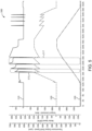
- a graph 500 depicting a plurality of curves 510, 520 and 530.
- Curve 510 illustrates the variation in magnitude of an electric motor torque command from SCM 138 as a function of time.
- Curve 520 illustrates the variation in the speed of electric motor 126 in response to variation in the electric motor torque command from SCM 138 as a function of time.
- Curve 530 indicates illustrates variation in the transmission output speed in response to variation in the speed of electric motor 126.
- Curves 510, 520 and 530 illustrate a plurality of shift events including shift events 515 and 517 as well as other shift events that are not labeled in the interest of preserving clarity.
- the electric motor torque command from SCM 138 illustrated by curve 510 is ramped down rapidly to a negative or braking torque.
- the speed of motor 126 ramped down to a value corresponding to a winning motor operation request as indicated by the triangular valleys of curve 520.
- the electric motor torque command from SCM 138 illustrated by curve 510 is ramped up to a positive torque value which is effective to restore the pre-shift operation of motor 126 as indicated by curve 520.
- the electric motor torque command from SCM 138 includes a speed command overshoot indicated by the maximum magnitude of curve 510 during a shift event followed by a restoration of the pre-shift command magnitude.
- Shift event process 200 may be initiated when GSCM 132 generates a message 221 indicating a gear shift request (e.g., a requested transmission gear).
- the message 221 may be generated in response to an operator input to shift lever 142 or other vehicle controls.
- the message 221 is then transmitted to TCM 134 and SCM 138 over vehicle CAN 194.
- Shift event process 200 next proceeds to conditional 204.
- SCM 138 evaluates whether a supervisory transmission mode change inhibit condition (STXI) is true.
- STXI may be, for example, a gear shift inhibit request which is generated based upon an evaluation performed by SCM 138. This evaluation may be based upon multiple criteria. For example, a mode change event may be inhibited if one or more of the following conditions is true: battery state of charge (SOC) is too low (e.g.
- SCM 138 evaluates that a transmission shift inhibit request is true, it generates a message 228 indicating that mode changes are inhibited and transmits the message 228 to TCM 134 over a CAN network such as vehicle CAN 194 or powertrain CAN 196.
- a CAN network such as vehicle CAN 194 or powertrain CAN 196.
- the system can be provided with communications controls that are calibratible to provide communication of the message over any or all of the CAN networks with which SCM 138 is in operative communication. This calibratible flexibility may be provided for all of the CAN-based communications described herein.
- TCM 134 inhibits gear shifting and generates and transmits a message 229 to GSCM 132 via vehicle CAN 194 indicating that an operator perceptible indication that the gear shift is inhibited should be provided.
- the GSCM 132 provides an operator perceptible indication that the gear shift is inhibited, for example, providing an output on a display.
- TCM 134 may also evaluate whether an internal transmission mode change inhibit condition (ITXI).
- ITXI may be, for example, a gear shift inhibit request which is generated based upon an evaluation performed by TCM 134 of its own operating conditions indicating the state of the transmission with which it is operatively coupled. This evaluation may be based upon multiple criteria. For example, TCM 134 may inhibit shifting when it has already received or is already executing another a conflicting operation, or when it is experiencing an error condition.
- TCM 134 If conditional 206 evaluates that the ITXI is true, TCM 134 generates a message 227 and transmits the message 227 over a CAN network such as vehicle CAN 194 or powertrain CAN 196.
- Message 227 indicates to SCM 138 that TCM 134 is self-inhibited from and SCM may respond to message 227 by returning to and repeating the evaluation of conditional 204 or by terminating the process 200 and awaiting receipt of a new message such as message 221.
- TCM 134 If conditional 206 evaluates that the ITXI is false, TCM 134 generates messages 231, 231, 233 and 234, and transmits the messages 231, 231, 233 and 234 over a CAN network such as vehicle CAN 194 or powertrain CAN 196.
- message 231 indicates a requested torque (or a requested torque and a requested and speed) of the motor for execution of the shift event
- message 232 indicates whether a shift event is in progress
- message 233 indicates a selected gear for the shift event (e.g., a gear to which the transmission intends to shift)
- message 234 indicates the current gear of the transmission.
- messages 231, 232, 233, and 234 are separate messages.
- SCM 138 evaluates whether the requested torque (or the requested torque and speed) of the motor for execution of the shift event can be provided. This evaluation may be performed by SCM 138 sending a message including a motor torque and speed request to MCM 136 and receiving from the MCM 136 a message indicating the motor torque and speed that can be provided in response to the request.
- the SCM may evaluate with conditional 208 whether the motor torque and speed that can be provided are sufficiently close to the requested motor torque and speed ( e.g ., within a predetermined margin) to successfully execute a shift event.
- SCM 138 evaluates that the requested torque and speed of the motor for execution of the shift event cannot be provided, it inhibits gear shifting and generates and transmits message 226 indicating that gear shifts are not inhibited and transmits the message to TCM 134 over a CAN network such as vehicle CAN 194 or powertrain CAN 196.
- TCM 134 inhibits gear shifting and generates and transmits a message 229 to GSCM 132 via vehicle CAN 194 indicating that an operator perceptible indication that the gear shift is inhibited should be provided.
- the GSCM 132 provides an operator perceptible indication that the gear shift is inhibited, for example, providing an output on a display.
- SCM 138 evaluates that the requested torque and speed of the motor for execution of the shift event can be provided, it generates and sends a message to MCM 136 to provide the commanded motor torque and speed.
- SCM 138 also generates a message 222 indicating a commanded motor speed and a message 224 indicating a commanded motor torque and transmits the message 222 and the message 224 to TCM 134 over a CAN network such as vehicle CAN 194 or powertrain CAN 196.
- TCM 134 executes a gear shift, updates the current gear, and generates and transmits a message 211 to GSCM 132 via vehicle CAN 194 indicating the updated current gear.
- the GSCM 132 provides an operator perceptible indication of the updated current gear.
- a direction of vehicle operation is determined by the foregoing acts of coordination among the supervisory control module, transmission control module, and gear shift control module.
- the powertrain including the automated manual transmission
- the one or more acts of coordination include the supervisory control module comparing its internal vehicle direction state with an internal vehicle direction state of one or both of the one or both of the transmission control module and the gear shift control module and inhibiting vehicle operation if the compared vehicle direction states differ from one another.
- the supervisory control module and the transmission control module assume the same internal vehicle direction state once the vehicle system direction request from the driver has been accepted as a result of the operations illustrated and described in connection with Fig. 2 .
- the supervisory control module is configured to spin the motor in the reverse direction once the vehicle system direction request has been accepted and a selected reverse gear has been engaged it being appreciated that the selected reverse gear may be a forward gear which is driven in reverse by the motor.
- the supervisory control module prevents erroneous vehicle operation in the direction not requested by a vehicle operator.
- the supervisory control module prevents erroneous vehicle operation by comparing its internal vehicle direction state with an internal vehicle direction state of the transmission control module.
- the supervisory control module prevents erroneous vehicle operation by comparing its internal vehicle direction state with an internal vehicle direction state of the gear shift control module.
- the supervisory control module is configured to transmit signals with the appropriate sign convention for forward, reverse, and neutral states.
- the sign convention is applied to signals include for torque, speed and/or other rotational parameters.
- the supervisory control module is configured to move into the neutral state after a key on/off event.
- the supervisory control module is configured to maintain zero vehicle speed for a configurable period of time by providing torque commands to the motor while the vehicle system is positioned on a grade greater than a predetermined magnitude, for example, a grade of 2% or greater, a grade of 3% or greater, a grade of 4% or greater or another predetermined grade.
- Supervisory control logic 300 includes 300 includes EV AMT supervisor block 302 which receives a plurality of inputs via vehicle CAN 194 or a CAN network of the low voltage wiring harness 191 including, operator commands or driver request, power limits, look-ahead information, and motor information such as motor current, motor speed, motor power and motor temperature, and battery information such as battery current, battery power, battery state of charge, and battery state of health.
- EV AMT supervisor block 302 which receives a plurality of inputs via vehicle CAN 194 or a CAN network of the low voltage wiring harness 191 including, operator commands or driver request, power limits, look-ahead information, and motor information such as motor current, motor speed, motor power and motor temperature, and battery information such as battery current, battery power, battery state of charge, and battery state of health.
- EV AMT supervisor block 302 utilizes the received inputs to determine a plurality of outputs and transmits these outputs via vehicle CAN 194 or low voltage wiring harness 191 including system power limits or operating limits, a shift inhibit request, requested gear based on look-ahead information and the currently selected gear, and rate limits for torque interrupts.
- EV AMT supervisor block 302 may determine the system power limits or operating limits based upon one or more motor limits such as a motor current limit, a motor speed limit, a motor power limit, and/or a motor temperature limit. EV AMT supervisor block 302 may determine the system power limits or operating limits based upon one or more battery limits such as a battery current limit, a battery power limit, a battery state of charge limit, and a battery state of health limit. EV AMT supervisor block 302 may determine the shift inhibit request based upon an evaluation of a supervisory transmission mode change inhibit condition (STXI) as described above in connection with process 200.
- STXI supervisory transmission mode change inhibit condition
- EV AMT supervisor block 302 may determine the requested gear based on look-ahead information and the currently selected gear by evaluating a predicted vehicle load based in part upon a future road grade, determining a desired gear based upon the predicted vehicle load and the current engine speed and current engine load, and determining a requested gear shift based upon the desired gear and the current gear.
- EV AMT supervisor block 302 may determine the rate limits for torque interrupts based upon operational limits of the motor and/or the battery which may include predetermined limits and which may be based upon the present operational state of the motor and/or the battery.
- the supervisory control logic includes 300 includes torque and acceleration request block 306 which receives one or more motor torque, speed (N) or acceleration (NDOT) requests and associated priorities from TCM 134 via vehicle CAN 194 or low voltage wiring harness 191.
- Torque and acceleration request block 306 outputs a set of one or more acceleration (NDOT) requests 308 and a set of corresponding torque requests 310 based on the inputs that it receives and provides these outputs to arbitration block 312 which selects winning torque and NDOT request from the inputs that it receives.
- Arbitration block 312 may select winning torque and NDOT requests in accordance with the techniques described hereinabove in connection with SCM 138.
- Arbitration block 312 provides the selected winning request to NDOT inner loop controller 314 which determines motor torque and speed or acceleration values based on the inputs that it receives. These motor torque and speed or acceleration values are provided to limiter block 316 which imposes limits on the motor torque and speed or acceleration values. The limited motor torque and speed or acceleration values are provided to power split and system limits block 318 which uses power split logic, system limits logic, and operating modes logic to determine torque and speed commands 320 for motor 126 which are provided to MCM 136 via low voltage wiring harness 191.
- Fig. 4 there is illustrated a schematic diagram depicting certain aspects of low voltage wiring harness 191.
- lines 411 indicate analog bus inputs/outputs
- lines 413 indicate digital bus inputs/outputs
- lines 411 indicate CAN busses with inline terminations
- lines 414 indicate protective circuits or fuses
- lines 415 indicate grounded power connections.
- Fig. 4 further illustrates a low voltage battery 427 which is connected to one of lines 415 in addition to the power provided by ESS 127.
Landscapes
- Engineering & Computer Science (AREA)
- Transportation (AREA)
- Mechanical Engineering (AREA)
- Chemical & Material Sciences (AREA)
- Combustion & Propulsion (AREA)
- Automation & Control Theory (AREA)
- Power Engineering (AREA)
- Human Computer Interaction (AREA)
- Electric Propulsion And Braking For Vehicles (AREA)
- Control Of Transmission Device (AREA)
Claims (15)
- Fahrzeugsystem (100) umfassend:einen Antriebsstrang einschließlich eines elektrischen Motors (126) betriebsmäßig gekoppelt mit einem automatisierten manuellen Getriebe; undein elektronisches Steuersystem einschließlich eines Gangschaltungssteuermoduls (132), eines Getriebesteuermoduls (134) und eines Motorsteuermoduls (136) in betrieblicher Kommunikation miteinander über ein oder mehrere Steuerbereichsnetzwerke;wobei das elektronische Steuersystem eine Hauptsteuerung (138) einschließt, die zu Folgendem konfiguriert ist:Vermitteln zwischen einer Mehrzahl von Motorbetriebsanforderungen, die über das eine oder die mehreren Steuerbereichsnetzwerke empfangen werden, um eine gewinnende Motorbetriebsanforderung auszuwählen, wobei jede der Mehrzahl von Motorbetriebsanforderungen einen Parameter einschließen, der eine angeforderte Operation des Motors und einen Prioritätsparameter angibt, wobei die Hauptsteuerung zwischen der Mehrzahl von Motorbetriebsanforderungen durch Auswerten des Prioritätsparameters vermittelt, wobei die Mehrzahl von Motorbetriebsanforderungen eine Drehmomentanforderung von einem Bediener einschließen,Auswerten einer oder mehrerer Schaltungsverhinderungsbedingungen, undBefehlen an den elektrischen Motor (126), die gewinnende Motorbetriebsanforderung bereitzustellen, wenn keine der einen oder mehreren Schaltungsverhinderungsbedingungen als wahr ausgewertet werden.
- Fahrzeugsystem nach Anspruch 1, wobei die Hauptsteuerung konfiguriert ist, an den elektrischen Motor (126) zu befehlen, die gewinnende Motorbetriebsanforderung durch Hoch- oder Herunterfahren von aktuellen Motordrehmoment-, Motordrehzahl- und Motorleistungswerten zu neuen Motordrehmoment-, Motordrehzahl- und Motordrehmomentwerten entsprechend der gewinnenden Motorbetriebsanforderung bereitzustellen.
- Fahrzeugsystem nach Anspruch 1, wobei die Hauptsteuerung konfiguriert ist, (a) in Antwort auf eine Gangschaltungsanforderung eine nicht-schaltende Antwort des Motorsteuermoduls auf eine Bediener-Drehmomentanforderung zu suspendieren, und (b) die Suspendierung der nicht-schaltenden Antwort des Motorsteuermoduls in Antwort auf den Abschluss einer Gangschaltung aufzuheben.
- Fahrzeugsystem nach Anspruch 1, wobei die eine oder mehreren Schaltungsverhinderungsbedingungen eines oder mehrere der Folgenden umfassen:ein Batterieladezustand (SOC) liegt unterhalb einer SOC-Grenze,ein Batteriekontaktor ist offen,ein Schlüsselschalter steht auf Aus,eine oder mehrere Systemleistungsgrenzen liegen unterhalb einer Systemleistungsgrenze,ein Batterieladesystem ist verbunden,ein oder mehrere Systemfehler sind aktiv,Betriebsbremsen sind inaktiv und ein Bedienerbefehl zu fahren ist wahr,eine vom Bediener angeforderte Fahrzeugrichtung ändert sich während das Fahrzeugsystem nicht stationär ist, und Vorausschauinformation zeigt an, dass eine Gangschaltung verhindert werden sollte.
- Fahrzeugsystem nach Anspruch 1 wobei:mindestens eins der einen oder mehreren Steuerbereichsnetzwerke durch eine Niederspannungsverkabelung bereitgestellt ist, oderdas eine oder die mehreren Steuerbereichsnetzwerke ein Fahrzeugsteuerbereichsnetzwerk, ein Antriebsstrangsteuerbereichsnetzwerk, ein Dienststeuerbereichsnetzwerk und ein privates Steuerbereichsnetzwerk einschließen, oderdas eine oder die mehreren Steuerbereichsnetzwerke ein Fahrzeugsteuerbereichsnetzwerk, ein Antriebsstrangsteuerbereichsnetzwerk, ein Dienststeuerbereichsnetzwerk und ein privates Steuerbereichsnetzwerk einschließen und mindestens eins der einen oder mehreren Steuerbereichsnetzwerke durch eine Niederspannungsverkabelung bereitgestellt ist, oderdie Hauptsteuerung im Motorsteuermodul implementiert ist.
- Fahrzeugsystem nach Anspruch 1, wobei eins der Folgenden existiert: (a) der Antriebsstrang schließt eines von einem Antrieb und einer Brennstoffzelle ein, (b) der Antriebsstrang ist konfiguriert als ein reichweite-erweitertes elektrisches Antriebssystem einschließlich eines Antriebs, der zum Antreiben eines Generators zum Bereitstellen von elektrischer Energie für den Motor konfiguriert ist, und (c) der Antriebsstrang als ein paralleles hybrides Antriebssystem konfiguriert ist, wobei eines oder beide von einem Antrieb und einem elektrischen Motor betriebsfähig sind, um Drehmoment zum Antreiben des Fahrzeugsystems bereitzustellen.
- Fahrzeugsystem nach Anspruch 1, wobei die Hauptsteuerung in einem Hauptsteuermodul bereitgestellt ist, wobei das Hauptsteuermodul und das Motorsteuermodul physisch separate Vorrichtungen sind.
- Fahrzeugsystem nach einem der Ansprüche 1-7, wobeider Antriebsstrang keinen physischen Rückwärtsgang aufweist, und Rückwärtsbetrieb des Fahrzeugsystems durch Rückwärtsrotation des elektrischen Motors bereitgestellt wird, odereine Richtung des Fahrzeugbetriebs durch eine oder mehrere Aktionen der Koordination zwischen der Hauptsteuerung, dem Getriebesteuermodul und dem Gangschaltungssteuermodul bestimmt ist, odereine Richtung des Fahrzeugbetriebs durch eine oder mehrere Aktionen der Koordination zwischen der Hauptsteuerung, dem Getriebesteuermodul und dem Gangschaltungssteuermodul bestimmt ist und die eine oder mehreren Aktionen der Koordination einschließen, dass die Hauptsteuerung einen ersten Fahrzeugrichtungszustand, der intern in der Hauptsteuerung besteht, mit einem zweiten internen Fahrzeugrichtungszustand eines des Getriebesteuermoduls und des Gangschaltungssteuermoduls vergleicht, oderdie Hauptsteuerung und das Getriebesteuermodul denselben internen Fahrzeugrichtungszustand annehmen, sobald die Fahrzeugsystemrichtungsanforderung vom Fahrer vom System akzeptiert worden ist, oderdie Hauptsteuerung konfiguriert ist, den Motor in einer Rückwärtsrichtung zu drehen, sobald die Fahrzeugsystemrichtungsanforderung akzeptiert worden ist und der gewählte Rückwärtsgang eingelegt worden ist, oderdie Hauptsteuerung irrtümlichen Fahrzeugbetrieb in der vom Fahrzeugbediener nicht angeforderten Richtung verhindert, oderdie Hauptsteuerung irrtümlichen Fahrzeugbetrieb durch Vergleichen eines ersten internen Fahrzeugrichtungszustands mit einem zweiten internen Fahrzeugrichtungszustand des Getriebesteuermoduls verhindert, oderdie Hauptsteuerung konfiguriert ist, Signale für mindestens eines von Drehmoment, Drehzahl und anderen rotationsmäßigen Antriebsparametern zu übertragen mit einer Vorzeichenkonvention, die einen von einem Vorwärtszustand, einem Rückwärtszustand und einem neutralen Zustand angibt, oderdie Hauptsteuerung konfiguriert ist, zumindest eine der folgenden Aktionen auszuführen: Initialisieren in einen neutralen Zustand nach einem Schlüssel-an-Ereignis und Umstellen in einen neutralen Zustand nach einem Schlüssel-aus-Ereignis und vor dem Abschließen einer Systemabschaltung, oderdie Hauptsteuerung konfiguriert ist, eine Fahrzeuggeschwindigkeit von Null für eine konfigurierbare Zeitperiode aufrecht zu erhalten durch Bereitstellen von Drehmomentbefehlen an den Motor während das Fahrzeugsystem auf einer Steigung positioniert ist, die größer als eine vorherbestimmte Größe ist.
- Fahrzeugsystem nach Anspruch 1, wobei das Gangschaltungssteuermodul konfiguriert ist, eine Meldung zu erzeugen, die einen angeforderten Getriebemodus in Antwort auf einen Bedienerbefehl angibt, und die Meldung an das Getriebesteuermodul und die Hauptsteuerung über das eine oder die mehreren Steuerbereichsnetzwerke zu übertragen.
- Fahrzeugsystem nach Anspruch 9, wobei:die Hauptsteuerung auswertet, ob eine Verhinderungsanforderung für eine Getriebemodusänderung wahr ist, und, wenn die Verhinderungsanforderung für eine Getriebemodusänderung wahr ist, eine Meldung erzeugt, die angibt, dass Getriebemodusänderungen verhindert sind, und die Meldung an das Getriebesteuermodul über das eine oder die mehreren Steuerbereichsnetzwerke überträgt, oderdie Hauptsteuerung auswertet, ob eine Verhinderungsanforderung für eine Getriebemodusänderung wahr ist, und, wenn die Verhinderungsanforderung für eine Getriebemodusänderung nicht wahr ist, die Hauptsteuerung eine Meldung erzeugt, die angibt, dass Gangschaltungen nicht verhindert sind, und die Meldung an das Getriebesteuermodul über das eine oder die mehreren Steuerbereichsnetzwerke überträgt und in Antwort auf die Meldung das Getriebesteuermodul auswertet, ob eine interne Schaltungsverhindergungsbedingung wahr ist, oderdas Hauptsteuermodul über das eine oder die mehreren Steuerbereichsnetzwerke ein oder mehrere Signale empfängt, die den aktuellen Gang des Getriebes, den gewählten Gang für das Schaltereignis, eine Angabe, ob ein Schaltereignis im Gange ist, und ein angefordertes Drehmoment und eine angeforderte Drehzahl des Motors zum Ausführen des Schaltereignisses angeben und, in Antwort, die Hauptsteuerung auswertet, ob das angeforderte Drehmoment und die angeforderte Drehzahl des Motors zum Ausführen des Schaltereignisses bereitgestellt werden können, oderdas Hauptsteuermodul über das eine oder die mehreren Steuerbereichsnetzwerke ein oder mehrere Signale empfängt, die den aktuellen Gang des Getriebes, den gewählten Gang für das Schaltereignis, eine Angabe, ob ein Schaltereignis im Gange ist, und ein angefordertes Drehmoment und eine angeforderte Drehzahl des Motors zum Ausführen des Schaltereignisses angeben und, in Antwort, die Hauptsteuerung auswertet, ob das angeforderte Drehmoment und die angeforderte Drehzahl des Motors zum Ausführen des Schaltereignisses bereitgestellt werden können, und eins der Folgenden ausführt: (a) wenn die Hauptsteuerung auswertet, dass das angeforderte Drehmoment und die angeforderte Drehzahl des Motors zum Ausführen des Schaltereignisses nicht bereitgestellt werden können, die Hauptsteuerung Gangschalten verhindert und eine Meldung erzeugt und an das Gangschaltsteuermodul über das eine oder die mehreren Steuerbereichsnetzwerke überträgt, die angibt, dass eine vom Bediener wahrnehmbare Anzeige, dass die Gangschaltung verhindert ist, bereitgestellt werden sollte, und (b) wenn die Hauptsteuerung auswertet, dass das angeforderte Drehmoment und die angeforderte Drehzahl des Motors zum Ausführen des Umschaltereignisses bereitgestellt werden können, die Hauptsteuerung eine Meldung erzeugt und an das Motorsteuermodul sendet, um das befohlene Drehmoment und die befohlene Drehzahl bereitzustellen und eine Meldung erzeugt und an das Getriebesteuermodul sendet, die das befohlene Motordrehmoment und die befohlene Motordrehzahl angibt.
- Verfahren zum Steuern des Betriebs eines Fahrzeugantriebsstrangs, wobei das Verfahren Folgendes umfasst:Betreiben eines elektrischen Steuersystems zum Steuern eines elektrischen Motors (126) des Fahrzeugsystemantriebsstrangs zum Bereitstellen eines Drehmoments an ein automatisiertes manuelles Getriebe, wobei das elektronische Steuersystem ein Gangschaltungssteuermodul (132), ein Getriebesteuermodul (134) und ein Motorsteuermodul (136) in betrieblicher Kommunikation mit einem oder mehreren Steuerbereichsnetzwerken einschließt, wobei das elektronische Steuersystem eine Hauptsteuerung (138) implementiert in einem oder beiden des Motorsteuermoduls und eines Hauptsteuermoduls (138) in betrieblicher Kommunikation mit dem einen oder den mehreren Steuerbereichsnetzwerken einschließt;Betreiben der Hauptsteuerung zum Vermitteln zwischen einer Mehrzahl von Motorbetriebsanforderungen, die über das eine oder die mehreren Steuerbereichsnetzwerke (194) empfangen werden, um eine gewinnende Motorbetriebsanforderung auszuwählen, wobei jede der empfangenen Mehrzahl von Motorbetriebsanforderungen einen Parameter einschließt, der eine angeforderte Operation des Motors und einen Prioritätsparameter angibt, wobei die Hauptsteuerung zwischen der Mehrzahl von Motorbetriebsanforderungen durch Auswerten des Prioritätsparameters vermittelt, wobei die Mehrzahl von Motorbetriebsanforderungen eine Drehmomentanforderung von einem Bediener einschließen,Betreiben der Hauptsteuerung zum Auswerten einer oder mehrerer Schaltungsverhinderungsbedingungen, undBetreiben der Hauptsteuerung zum Befehlen an den elektrischen Motor, die gewinnende Motorbetriebsanforderung bereitzustellen, wenn keine der einen oder mehreren Schaltungsverhinderungsbedingungen als wahr ausgewertet werden.
- Verfahren nach Anspruch 11, umfassend:Betreiben der Hauptsteuerung zum Befehlen an den elektrischen Motor (126), die gewinnende Motorbetriebsanforderung durch Hoch- oder Herunterfahren von aktuellen Motordrehmoment-, Motordrehzahl- und Motorleistungswerten zu neuen Motordrehmoment-, Motordrehzahl- und Motordrehmomentwerten entsprechend der gewinnenden Motorbetriebsanforderung bereitzustellen.Betreiben der Hauptsteuerung zum (a) Suspendieren einer nicht-schaltenden Antwort des Motorsteuermoduls (136) auf eine Drehmomentanforderung vom Bediener in Antwort auf eine Gangschaltanforderung, und (b) Aufheben der Suspendierung der nicht-schaltenden Antwort des Motorsteuermoduls in Antwort auf den Abschluss einer Gangschaltung, oderdie eine oder mehreren Verhinderungsbedingungen umfassen eines oder mehrere der Folgenden: ein Batterieladezustand (SOC) liegt unterhalb einer SOC-Grenze, ein Batteriekontaktor ist offen, ein Schlüsselschalter steht auf Aus, eine oder mehrere Systemleistungsgrenzen liegen unterhalb einer Systemleistungsgrenze, ein Batterieladesystem ist verbunden, ein oder mehrere Systemfehler sind aktiv, Betriebsbremsen sind inaktiv und ein Bedienerbefehl zu fahren ist wahr, eine vom Bediener angeforderte Fahrzeugrichtung ändert sich, während das Fahrzeugsystem nicht stationär ist, und Vorausschauinformation zeigt an, dass eine Gangschaltung verhindert werden sollte, odermindestens eins der einen oder mehreren Steuerbereichsnetzwerke (194) ist durch eine Niederspannungsverkabelung bereitgestellt, oderdas eine oder die mehreren Steuerbereichsnetzwerke (194) schließen ein Fahrzeugsteuerbereichsnetzwerk, ein Antriebsstrangsteuerbereichsnetzwerk, ein Dienststeuerbereichsnetzwerk und ein privates Steuerbereichsnetzwerk ein, odermindestens eins der einen oder mehreren Steuerbereichsnetzwerke ist durch eine Niederspannungsverkabelung bereitgestellt.
- Verfahren nach einem der Ansprüche 11-12, wobei:der Antriebsstrang keinen physischen Rückwärtsgang aufweist, und Rückwärtsbetrieb des Fahrzeugsystems durch Rückwärtsrotation des elektrischen Motors bereitgestellt wird, odereine Richtung des Fahrzeugbetriebs durch eine oder mehrere Aktionen der Koordination zwischen der Hauptsteuerung, dem Getriebesteuermodul und dem Gangschaltungssteuermodul koordiniert bestimmt ist, odereine Richtung des Fahrzeugbetriebs durch eine oder mehrere Aktionen der Koordination zwischen der Hauptsteuerung, dem Getriebesteuermodul und dem Gangschaltungssteuermodul koordiniert bestimmt ist und der eine oder die mehreren Aktionen der Koordination einschließen, dass die Hauptsteuerung einen ersten Fahrzeugrichtungszustand, der intern in der Hauptsteuerung besteht, mit einem zweiten internen Fahrzeugrichtungszustand, der intern in einem oder beiden des Getriebesteuermoduls und des Gangschaltungssteuermoduls besteht, vergleicht, oderdie Hauptsteuerung (138) und das Getriebesteuermodul (134) denselben internen Fahrzeugrichtungszustand annehmen, sobald die Fahrzeugsystemrichtungsanforderung vom Fahrer vom System akzeptiert worden ist, oderdie Hauptsteuerung den Motor in der Rückwärtsrichtung dreht, sobald die Fahrzeugsystemrichtungsanforderung akzeptiert worden ist und der gewählte Rückwärtsgang eingelegt worden ist, oderdie Hauptsteuerung irrtümlichen Fahrzeugbetrieb in der von einem Fahrzeugbediener nicht angeforderten Richtung verhindert, oderdie Hauptsteuerung irrtümlichen Fahrzeugbetrieb durch Vergleichen ihres internen Fahrzeugrichtungszustands mit einem internen Fahrzeugrichtungszustand des Getriebesteuermoduls verhindert, oderdie Hauptsteuerung Signale für eines oder mehrere von Drehmoment und Drehzahl überträgt mit einer Vorzeichenkonvention, die einen von einem Vorwärtszustand, einem Rückwärtszustand und einem neutralen Zustand angibt, oderdie Hauptsteuerung zumindest eine der folgenden Aktionen ausführt: Initialisieren in einen neutralen Zustand nach einem Schlüssel-an-Ereignis und Umstellen in einen neutralen Zustand nach einem Schlüssel-aus-Ereignis und vor dem Abschließen einer Systemabschaltung, oderdie Hauptsteuerung eine Fahrzeuggeschwindigkeit von Null für eine konfigurierbare Zeitperiode aufrecht erhält durch Bereitstellen von Drehmomentbefehlen an den Motor, während das Fahrzeugsystem auf einer Steigung positioniert ist, die größer als eine vorherbestimmte Größe ist.
- Verfahren nach Anspruch 11 wobei die Gangschaltungssteuerung eine Meldung erzeugt, die einen angeforderten Getriebemodus in Antwort auf einen Bedienerbefehl angibt, und die Meldung an das Getriebesteuermodul und die Hauptsteuerung über das eine oder die mehreren Steuerbereichsnetzwerke überträgt.
- Verfahren nach Anspruch 14 wobei:
die Hauptsteuerung auswertet, ob eine Verhinderungsanforderung für eine Getriebeschaltung wahr ist, und eins der Folgenden ausführt: (a) wenn die Schaltungsverhinderungsanforderung wahr ist, die Hauptsteuerung eine Meldung erzeugt, die angibt, dass Schalten verhindert ist, und die Meldung an das Getriebesteuermodul über das eine oder die mehreren Steuerbereichsnetzwerke übertragt, und (b) wenn die Schaltungsverhinderungsanforderung nicht wahr ist, die Hauptsteuerung eine Meldung erzeugt, die angibt, dass Gangschaltungen nicht verhindert sind, und die Meldung an das Getriebesteuermodul über das eine oder die mehreren Steuerbereichsnetzwerke überträgt, wobei in Antwort auf die Meldung das Getriebesteuermodul auswertet, ob eine interne Schaltungsverhinderungsbedingung wahr ist.
Applications Claiming Priority (2)
| Application Number | Priority Date | Filing Date | Title |
|---|---|---|---|
| US201862775977P | 2018-12-06 | 2018-12-06 | |
| PCT/US2019/064227 WO2020117798A1 (en) | 2018-12-06 | 2019-12-03 | Powertrain controls for an electric motor and an automated manual transmission |
Publications (3)
| Publication Number | Publication Date |
|---|---|
| EP3833588A1 EP3833588A1 (de) | 2021-06-16 |
| EP3833588A4 EP3833588A4 (de) | 2022-05-04 |
| EP3833588B1 true EP3833588B1 (de) | 2024-08-21 |
Family
ID=70975492
Family Applications (1)
| Application Number | Title | Priority Date | Filing Date |
|---|---|---|---|
| EP19892595.0A Active EP3833588B1 (de) | 2018-12-06 | 2019-12-03 | Antriebsstrangsteuerelemente für einen elektromotor und automatisiertes schaltgetriebe |
Country Status (4)
| Country | Link |
|---|---|
| US (1) | US12115970B2 (de) |
| EP (1) | EP3833588B1 (de) |
| CN (1) | CN112654544B (de) |
| WO (1) | WO2020117798A1 (de) |
Families Citing this family (9)
| Publication number | Priority date | Publication date | Assignee | Title |
|---|---|---|---|---|
| US10322688B2 (en) * | 2016-12-30 | 2019-06-18 | Textron Innovations Inc. | Controlling electrical access to a lithium battery on a utility vehicle |
| DE102018208425B4 (de) * | 2018-05-28 | 2026-01-29 | Bayerische Motoren Werke Aktiengesellschaft | Antriebsstrang für ein Kraftfahrzeug, insbesondere für einen Kraftwagen, sowie Verfahren zum Betreiben eines solchen Antriebsstrangs |
| CN110654270B (zh) * | 2019-09-30 | 2021-08-20 | 潍柴动力股份有限公司 | 一种车辆充电控制方法及装置 |
| CN115285107A (zh) * | 2022-06-27 | 2022-11-04 | 中国第一汽车股份有限公司 | 一种基于混合动力系统的挡位切换方法及系统 |
| EP4559074A4 (de) * | 2022-07-22 | 2026-03-25 | Ticona Llc | Statorkern für ein elektrisches energiesystem |
| US20240253640A1 (en) * | 2023-02-01 | 2024-08-01 | GM Global Technology Operations LLC | Archtecture and execution of torque coordination for electric vehicle transmission shift controls |
| US12270351B2 (en) * | 2023-02-14 | 2025-04-08 | Schaeffler Technologies AG & Co. KG | Reversing method for a vehicle powertrain |
| US20250153721A1 (en) * | 2023-11-14 | 2025-05-15 | GM Global Technology Operations LLC | Propulsion arbitration system |
| CN118306229B (zh) * | 2024-06-07 | 2024-08-16 | 张家港长城汽车研发有限公司 | 车辆控制方法、电子设备及车辆 |
Family Cites Families (33)
| Publication number | Priority date | Publication date | Assignee | Title |
|---|---|---|---|---|
| DE19736406B4 (de) * | 1997-08-21 | 2007-05-16 | Siemens Ag | Einrichtung zum Steuern eines automatischen Getriebes für ein Kraftfahrzeug |
| US5993350A (en) * | 1997-12-01 | 1999-11-30 | Lawrie; Robert E. | Automated manual transmission clutch controller |
| US6145398A (en) * | 1998-02-20 | 2000-11-14 | New Venture Gear, Inc. | Electronically controlled shift system for a manual transmission |
| US6629026B1 (en) * | 2002-04-12 | 2003-09-30 | Ford Motor Company | Hybrid electric vehicle with motor torque fill in |
| US6883394B2 (en) * | 2002-10-15 | 2005-04-26 | Borgwarner, Inc. | Method for controlling the positioning of the synchronizers of a dual clutch transmission |
| US6915198B2 (en) * | 2003-09-11 | 2005-07-05 | Ford Global Technologies, Llc | Vehicle fast torque coordination |
| US7957873B2 (en) | 2007-03-09 | 2011-06-07 | GM Global Technology Operations LLC | Vehicle transmission shift inhibit method and apparatus |
| JP2009047216A (ja) | 2007-08-17 | 2009-03-05 | Isuzu Motors Ltd | 車両用変速機の変速制御装置 |
| CN100521501C (zh) * | 2007-09-30 | 2009-07-29 | 奇瑞汽车股份有限公司 | 一种混合动力电机扭矩管理方法 |
| US8112206B2 (en) * | 2007-11-04 | 2012-02-07 | GM Global Technology Operations LLC | Method for controlling a powertrain system based upon energy storage device temperature |
| JP4329864B2 (ja) | 2008-02-12 | 2009-09-09 | トヨタ自動車株式会社 | 車両用動力伝達装置の制御装置 |
| AR075776A1 (es) * | 2009-03-03 | 2011-04-27 | Honda Motor Co Ltd | Aparato de transmision de potencia para vehiculo hibrido |
| JP2013071551A (ja) * | 2011-09-27 | 2013-04-22 | Aisin Seiki Co Ltd | ハイブリッド車両の制御装置 |
| US8900095B2 (en) * | 2012-05-21 | 2014-12-02 | GM Global Technology Operations LLC | Automatic transmission synchronous gear shift |
| JP5987570B2 (ja) * | 2012-09-06 | 2016-09-07 | スズキ株式会社 | 自動変速機の変速制御装置 |
| US9297455B2 (en) | 2012-11-20 | 2016-03-29 | GM Global Technology Operations LLC | GPS-based predictive shift schedule for automatic transmission |
| US9005076B2 (en) | 2012-12-04 | 2015-04-14 | GM Global Technology Operations LLC | Method and apparatus for controlling a shift in a multi-mode powertrain system |
| CN105556183B (zh) | 2013-03-27 | 2018-05-29 | 沃尔沃卡车集团 | 用于车辆的动力传动系的控制方法和对应的受控动力传动系 |
| SE538355C2 (sv) | 2013-11-21 | 2016-05-24 | Scania Cv Ab | Förfarande för att styra en hybriddrivlina i ett fordon så att glapp elimineras medelst en elmaskin |
| US9718462B2 (en) * | 2014-01-10 | 2017-08-01 | Ford Global Technologies, Llc | Hybrid vehicle transmission shift management system and method |
| US9623879B2 (en) * | 2014-02-18 | 2017-04-18 | Honda Motor Co., Ltd. | System for operating vehicle in different driving modes and methods for same |
| US10183674B2 (en) * | 2015-04-23 | 2019-01-22 | Ford Global Technologies, Llc | Hybrid/electric vehicle motor control during step-ratio transmission engagement |
| US10208854B2 (en) | 2015-09-18 | 2019-02-19 | Ford Global Technologies, Llc | Terrain adaptive shift scheduling |
| EP3370987A4 (de) | 2015-11-04 | 2019-08-14 | Eaton Corporation | Übertragungssystem für elektrifizierung eines nutzfahrzeugantriebsstrangs |
| US9829099B2 (en) * | 2015-11-11 | 2017-11-28 | Ford Global Technologies, Llc | Transmission drive mode user selection systems and methods |
| US10189468B2 (en) * | 2016-02-26 | 2019-01-29 | Ford Global Technologies, Llc | Paddle shifter control of hybrid powertrain |
| US10948074B2 (en) | 2016-04-07 | 2021-03-16 | Eaton Cummins Automated Transmission Technologies, Llc | Methods for predictive shifting |
| US10023179B2 (en) | 2016-05-11 | 2018-07-17 | Ford Global Technologies, Llc | Minimizing engine pull-ups and gear shifts in a hybrid vehicle |
| US10549748B2 (en) * | 2017-02-27 | 2020-02-04 | Ford Global Technologies, Llc | Autonomous motor control during loss of motor communications |
| US10119481B2 (en) * | 2017-03-22 | 2018-11-06 | GM Global Technology Operations LLC | Coordination of torque interventions in MPC-based powertrain control |
| JP7006251B2 (ja) * | 2017-12-25 | 2022-01-24 | トヨタ自動車株式会社 | 電気機器の車載構造 |
| US10807588B2 (en) * | 2018-06-04 | 2020-10-20 | Ford Global Technologies, Llc | Powertrain control system and strategy for electrified vehicle |
| JP2020047972A (ja) | 2018-09-14 | 2020-03-26 | サクサ株式会社 | 画像処理装置 |
-
2019
- 2019-12-03 EP EP19892595.0A patent/EP3833588B1/de active Active
- 2019-12-03 WO PCT/US2019/064227 patent/WO2020117798A1/en not_active Ceased
- 2019-12-03 CN CN201980058183.3A patent/CN112654544B/zh active Active
-
2021
- 2021-02-17 US US17/178,094 patent/US12115970B2/en active Active
Also Published As
| Publication number | Publication date |
|---|---|
| EP3833588A1 (de) | 2021-06-16 |
| US20210179070A1 (en) | 2021-06-17 |
| CN112654544B (zh) | 2024-07-02 |
| CN112654544A (zh) | 2021-04-13 |
| WO2020117798A1 (en) | 2020-06-11 |
| EP3833588A4 (de) | 2022-05-04 |
| US12115970B2 (en) | 2024-10-15 |
Similar Documents
| Publication | Publication Date | Title |
|---|---|---|
| EP3833588B1 (de) | Antriebsstrangsteuerelemente für einen elektromotor und automatisiertes schaltgetriebe | |
| US7967091B2 (en) | Hybrid electric vehicle powertrain with engine start and transmission shift arbitration | |
| CN104773161B (zh) | 混合动力电动车辆 | |
| US6735502B2 (en) | Control system and method for a parallel hybrid electric vehicle | |
| CN103140400B (zh) | 车辆及控制方法 | |
| US20140228168A1 (en) | Powertrain configurations for single-motor, two-clutch hybrid electric vehicles | |
| KR101703613B1 (ko) | 하이브리드 차량의 엔진 기동 시점 제어 방법 및 그 제어 장치 | |
| US11085530B2 (en) | Active shift control method for power-off downshift of hybrid vehicle | |
| US20090239703A1 (en) | Hybrid powertrain and a method for controlling a hybrid powertrain | |
| KR101704191B1 (ko) | 하이브리드 차량의 토크 인터벤션 제어장치 및 제어방법 | |
| CN106167023A (zh) | 控制动力传动系统的系统和方法 | |
| CN109895778B (zh) | 混合动力车辆和该混合动力车辆的换挡控制方法 | |
| CN119078793A (zh) | 一种车辆控制方法、装置、存储介质和车辆 | |
| US10160445B2 (en) | Shift control method for hybrid electric vehicle | |
| CN121152727A (zh) | 控制混合动力车辆的发动机启动 | |
| JP4288171B2 (ja) | 自動車のドライブトレーンおよびドライブトレーンの制御方法 | |
| US9493168B1 (en) | Method and apparatus for controlling a control variable of a powertrain system | |
| US11440419B2 (en) | Method of controlling gear shifting in electric vehicle | |
| US12291189B2 (en) | Compensation method for shortfall of engine torque | |
| KR102371015B1 (ko) | 하이브리드 차량의 제어 방법 | |
| US11167749B2 (en) | Hybrid electric powertrain with engine torque-smoothing transition control logic | |
| CN104118426A (zh) | 在电气化车辆动力传动系中管理可用运行状态的方法 | |
| KR20230158674A (ko) | 하이브리드 자동차 및 그를 위한 주행 제어 방법 | |
| KR102501377B1 (ko) | 하이브리드 전기 차량의 최적 운전점 제어 방법 및 그 장치 | |
| KR102598557B1 (ko) | 하이브리드 차량의 정지전 다운시프트 제어 방법 |
Legal Events
| Date | Code | Title | Description |
|---|---|---|---|
| STAA | Information on the status of an ep patent application or granted ep patent |
Free format text: STATUS: THE INTERNATIONAL PUBLICATION HAS BEEN MADE |
|
| PUAI | Public reference made under article 153(3) epc to a published international application that has entered the european phase |
Free format text: ORIGINAL CODE: 0009012 |
|
| STAA | Information on the status of an ep patent application or granted ep patent |
Free format text: STATUS: REQUEST FOR EXAMINATION WAS MADE |
|
| 17P | Request for examination filed |
Effective date: 20210308 |
|
| AK | Designated contracting states |
Kind code of ref document: A1 Designated state(s): AL AT BE BG CH CY CZ DE DK EE ES FI FR GB GR HR HU IE IS IT LI LT LU LV MC MK MT NL NO PL PT RO RS SE SI SK SM TR |
|
| DAV | Request for validation of the european patent (deleted) | ||
| DAX | Request for extension of the european patent (deleted) | ||
| A4 | Supplementary search report drawn up and despatched |
Effective date: 20220407 |
|
| RIC1 | Information provided on ipc code assigned before grant |
Ipc: B60L 50/00 20190101ALI20220401BHEP Ipc: B60W 30/182 20200101ALI20220401BHEP Ipc: B60W 30/19 20120101AFI20220401BHEP |
|
| GRAP | Despatch of communication of intention to grant a patent |
Free format text: ORIGINAL CODE: EPIDOSNIGR1 |
|
| STAA | Information on the status of an ep patent application or granted ep patent |
Free format text: STATUS: GRANT OF PATENT IS INTENDED |
|
| INTG | Intention to grant announced |
Effective date: 20240326 |
|
| GRAS | Grant fee paid |
Free format text: ORIGINAL CODE: EPIDOSNIGR3 |
|
| GRAA | (expected) grant |
Free format text: ORIGINAL CODE: 0009210 |
|
| STAA | Information on the status of an ep patent application or granted ep patent |
Free format text: STATUS: THE PATENT HAS BEEN GRANTED |
|
| AK | Designated contracting states |
Kind code of ref document: B1 Designated state(s): AL AT BE BG CH CY CZ DE DK EE ES FI FR GB GR HR HU IE IS IT LI LT LU LV MC MK MT NL NO PL PT RO RS SE SI SK SM TR |
|
| REG | Reference to a national code |
Ref country code: GB Ref legal event code: FG4D |
|
| REG | Reference to a national code |
Ref country code: CH Ref legal event code: EP |
|
| REG | Reference to a national code |
Ref country code: IE Ref legal event code: FG4D |
|
| REG | Reference to a national code |
Ref country code: DE Ref legal event code: R096 Ref document number: 602019057643 Country of ref document: DE |
|
| P01 | Opt-out of the competence of the unified patent court (upc) registered |
Free format text: CASE NUMBER: UPC_APP_120753/2023 Effective date: 20230510 |
|
| REG | Reference to a national code |
Ref country code: LT Ref legal event code: MG9D |
|
| REG | Reference to a national code |
Ref country code: NL Ref legal event code: MP Effective date: 20240821 |
|
| PG25 | Lapsed in a contracting state [announced via postgrant information from national office to epo] |
Ref country code: NO Free format text: LAPSE BECAUSE OF FAILURE TO SUBMIT A TRANSLATION OF THE DESCRIPTION OR TO PAY THE FEE WITHIN THE PRESCRIBED TIME-LIMIT Effective date: 20241121 |
|
| REG | Reference to a national code |
Ref country code: AT Ref legal event code: MK05 Ref document number: 1715240 Country of ref document: AT Kind code of ref document: T Effective date: 20240821 |
|
| PG25 | Lapsed in a contracting state [announced via postgrant information from national office to epo] |
Ref country code: NL Free format text: LAPSE BECAUSE OF FAILURE TO SUBMIT A TRANSLATION OF THE DESCRIPTION OR TO PAY THE FEE WITHIN THE PRESCRIBED TIME-LIMIT Effective date: 20240821 Ref country code: FI Free format text: LAPSE BECAUSE OF FAILURE TO SUBMIT A TRANSLATION OF THE DESCRIPTION OR TO PAY THE FEE WITHIN THE PRESCRIBED TIME-LIMIT Effective date: 20240821 Ref country code: GR Free format text: LAPSE BECAUSE OF FAILURE TO SUBMIT A TRANSLATION OF THE DESCRIPTION OR TO PAY THE FEE WITHIN THE PRESCRIBED TIME-LIMIT Effective date: 20241122 Ref country code: PL Free format text: LAPSE BECAUSE OF FAILURE TO SUBMIT A TRANSLATION OF THE DESCRIPTION OR TO PAY THE FEE WITHIN THE PRESCRIBED TIME-LIMIT Effective date: 20240821 Ref country code: PT Free format text: LAPSE BECAUSE OF FAILURE TO SUBMIT A TRANSLATION OF THE DESCRIPTION OR TO PAY THE FEE WITHIN THE PRESCRIBED TIME-LIMIT Effective date: 20241223 |
|
| PG25 | Lapsed in a contracting state [announced via postgrant information from national office to epo] |
Ref country code: BG Free format text: LAPSE BECAUSE OF FAILURE TO SUBMIT A TRANSLATION OF THE DESCRIPTION OR TO PAY THE FEE WITHIN THE PRESCRIBED TIME-LIMIT Effective date: 20240821 |
|
| PG25 | Lapsed in a contracting state [announced via postgrant information from national office to epo] |
Ref country code: LV Free format text: LAPSE BECAUSE OF FAILURE TO SUBMIT A TRANSLATION OF THE DESCRIPTION OR TO PAY THE FEE WITHIN THE PRESCRIBED TIME-LIMIT Effective date: 20240821 |
|
| PG25 | Lapsed in a contracting state [announced via postgrant information from national office to epo] |
Ref country code: AT Free format text: LAPSE BECAUSE OF FAILURE TO SUBMIT A TRANSLATION OF THE DESCRIPTION OR TO PAY THE FEE WITHIN THE PRESCRIBED TIME-LIMIT Effective date: 20240821 Ref country code: IS Free format text: LAPSE BECAUSE OF FAILURE TO SUBMIT A TRANSLATION OF THE DESCRIPTION OR TO PAY THE FEE WITHIN THE PRESCRIBED TIME-LIMIT Effective date: 20241221 |
|
| PG25 | Lapsed in a contracting state [announced via postgrant information from national office to epo] |
Ref country code: HR Free format text: LAPSE BECAUSE OF FAILURE TO SUBMIT A TRANSLATION OF THE DESCRIPTION OR TO PAY THE FEE WITHIN THE PRESCRIBED TIME-LIMIT Effective date: 20240821 |
|
| PG25 | Lapsed in a contracting state [announced via postgrant information from national office to epo] |
Ref country code: ES Free format text: LAPSE BECAUSE OF FAILURE TO SUBMIT A TRANSLATION OF THE DESCRIPTION OR TO PAY THE FEE WITHIN THE PRESCRIBED TIME-LIMIT Effective date: 20240821 Ref country code: RS Free format text: LAPSE BECAUSE OF FAILURE TO SUBMIT A TRANSLATION OF THE DESCRIPTION OR TO PAY THE FEE WITHIN THE PRESCRIBED TIME-LIMIT Effective date: 20241121 |
|
| PG25 | Lapsed in a contracting state [announced via postgrant information from national office to epo] |
Ref country code: RS Free format text: LAPSE BECAUSE OF FAILURE TO SUBMIT A TRANSLATION OF THE DESCRIPTION OR TO PAY THE FEE WITHIN THE PRESCRIBED TIME-LIMIT Effective date: 20241121 Ref country code: PT Free format text: LAPSE BECAUSE OF FAILURE TO SUBMIT A TRANSLATION OF THE DESCRIPTION OR TO PAY THE FEE WITHIN THE PRESCRIBED TIME-LIMIT Effective date: 20241223 Ref country code: PL Free format text: LAPSE BECAUSE OF FAILURE TO SUBMIT A TRANSLATION OF THE DESCRIPTION OR TO PAY THE FEE WITHIN THE PRESCRIBED TIME-LIMIT Effective date: 20240821 Ref country code: NO Free format text: LAPSE BECAUSE OF FAILURE TO SUBMIT A TRANSLATION OF THE DESCRIPTION OR TO PAY THE FEE WITHIN THE PRESCRIBED TIME-LIMIT Effective date: 20241121 Ref country code: NL Free format text: LAPSE BECAUSE OF FAILURE TO SUBMIT A TRANSLATION OF THE DESCRIPTION OR TO PAY THE FEE WITHIN THE PRESCRIBED TIME-LIMIT Effective date: 20240821 Ref country code: LV Free format text: LAPSE BECAUSE OF FAILURE TO SUBMIT A TRANSLATION OF THE DESCRIPTION OR TO PAY THE FEE WITHIN THE PRESCRIBED TIME-LIMIT Effective date: 20240821 Ref country code: IS Free format text: LAPSE BECAUSE OF FAILURE TO SUBMIT A TRANSLATION OF THE DESCRIPTION OR TO PAY THE FEE WITHIN THE PRESCRIBED TIME-LIMIT Effective date: 20241221 Ref country code: HR Free format text: LAPSE BECAUSE OF FAILURE TO SUBMIT A TRANSLATION OF THE DESCRIPTION OR TO PAY THE FEE WITHIN THE PRESCRIBED TIME-LIMIT Effective date: 20240821 Ref country code: GR Free format text: LAPSE BECAUSE OF FAILURE TO SUBMIT A TRANSLATION OF THE DESCRIPTION OR TO PAY THE FEE WITHIN THE PRESCRIBED TIME-LIMIT Effective date: 20241122 Ref country code: FI Free format text: LAPSE BECAUSE OF FAILURE TO SUBMIT A TRANSLATION OF THE DESCRIPTION OR TO PAY THE FEE WITHIN THE PRESCRIBED TIME-LIMIT Effective date: 20240821 Ref country code: ES Free format text: LAPSE BECAUSE OF FAILURE TO SUBMIT A TRANSLATION OF THE DESCRIPTION OR TO PAY THE FEE WITHIN THE PRESCRIBED TIME-LIMIT Effective date: 20240821 Ref country code: BG Free format text: LAPSE BECAUSE OF FAILURE TO SUBMIT A TRANSLATION OF THE DESCRIPTION OR TO PAY THE FEE WITHIN THE PRESCRIBED TIME-LIMIT Effective date: 20240821 Ref country code: AT Free format text: LAPSE BECAUSE OF FAILURE TO SUBMIT A TRANSLATION OF THE DESCRIPTION OR TO PAY THE FEE WITHIN THE PRESCRIBED TIME-LIMIT Effective date: 20240821 |
|
| PG25 | Lapsed in a contracting state [announced via postgrant information from national office to epo] |
Ref country code: RO Free format text: LAPSE BECAUSE OF FAILURE TO SUBMIT A TRANSLATION OF THE DESCRIPTION OR TO PAY THE FEE WITHIN THE PRESCRIBED TIME-LIMIT Effective date: 20240821 Ref country code: DK Free format text: LAPSE BECAUSE OF FAILURE TO SUBMIT A TRANSLATION OF THE DESCRIPTION OR TO PAY THE FEE WITHIN THE PRESCRIBED TIME-LIMIT Effective date: 20240821 Ref country code: SM Free format text: LAPSE BECAUSE OF FAILURE TO SUBMIT A TRANSLATION OF THE DESCRIPTION OR TO PAY THE FEE WITHIN THE PRESCRIBED TIME-LIMIT Effective date: 20240821 |
|
| PG25 | Lapsed in a contracting state [announced via postgrant information from national office to epo] |
Ref country code: EE Free format text: LAPSE BECAUSE OF FAILURE TO SUBMIT A TRANSLATION OF THE DESCRIPTION OR TO PAY THE FEE WITHIN THE PRESCRIBED TIME-LIMIT Effective date: 20240821 |
|
| PG25 | Lapsed in a contracting state [announced via postgrant information from national office to epo] |
Ref country code: CZ Free format text: LAPSE BECAUSE OF FAILURE TO SUBMIT A TRANSLATION OF THE DESCRIPTION OR TO PAY THE FEE WITHIN THE PRESCRIBED TIME-LIMIT Effective date: 20240821 |
|
| PG25 | Lapsed in a contracting state [announced via postgrant information from national office to epo] |
Ref country code: IT Free format text: LAPSE BECAUSE OF FAILURE TO SUBMIT A TRANSLATION OF THE DESCRIPTION OR TO PAY THE FEE WITHIN THE PRESCRIBED TIME-LIMIT Effective date: 20240821 Ref country code: SK Free format text: LAPSE BECAUSE OF FAILURE TO SUBMIT A TRANSLATION OF THE DESCRIPTION OR TO PAY THE FEE WITHIN THE PRESCRIBED TIME-LIMIT Effective date: 20240821 |
|
| REG | Reference to a national code |
Ref country code: DE Ref legal event code: R097 Ref document number: 602019057643 Country of ref document: DE |
|
| PLBE | No opposition filed within time limit |
Free format text: ORIGINAL CODE: 0009261 |
|
| STAA | Information on the status of an ep patent application or granted ep patent |
Free format text: STATUS: NO OPPOSITION FILED WITHIN TIME LIMIT |
|
| PG25 | Lapsed in a contracting state [announced via postgrant information from national office to epo] |
Ref country code: MC Free format text: LAPSE BECAUSE OF FAILURE TO SUBMIT A TRANSLATION OF THE DESCRIPTION OR TO PAY THE FEE WITHIN THE PRESCRIBED TIME-LIMIT Effective date: 20240821 |
|
| 26N | No opposition filed |
Effective date: 20250522 |
|
| REG | Reference to a national code |
Ref country code: CH Ref legal event code: PL |
|
| PG25 | Lapsed in a contracting state [announced via postgrant information from national office to epo] |
Ref country code: LU Free format text: LAPSE BECAUSE OF NON-PAYMENT OF DUE FEES Effective date: 20241203 |
|
| PG25 | Lapsed in a contracting state [announced via postgrant information from national office to epo] |
Ref country code: SE Free format text: LAPSE BECAUSE OF FAILURE TO SUBMIT A TRANSLATION OF THE DESCRIPTION OR TO PAY THE FEE WITHIN THE PRESCRIBED TIME-LIMIT Effective date: 20240821 |
|
| REG | Reference to a national code |
Ref country code: BE Ref legal event code: MM Effective date: 20241231 |
|
| PG25 | Lapsed in a contracting state [announced via postgrant information from national office to epo] |
Ref country code: BE Free format text: LAPSE BECAUSE OF NON-PAYMENT OF DUE FEES Effective date: 20241231 |
|
| PG25 | Lapsed in a contracting state [announced via postgrant information from national office to epo] |
Ref country code: FR Free format text: LAPSE BECAUSE OF NON-PAYMENT OF DUE FEES Effective date: 20241231 |
|
| PG25 | Lapsed in a contracting state [announced via postgrant information from national office to epo] |
Ref country code: CH Free format text: LAPSE BECAUSE OF NON-PAYMENT OF DUE FEES Effective date: 20241231 |
|
| PG25 | Lapsed in a contracting state [announced via postgrant information from national office to epo] |
Ref country code: IE Free format text: LAPSE BECAUSE OF NON-PAYMENT OF DUE FEES Effective date: 20241203 |
|
| PGFP | Annual fee paid to national office [announced via postgrant information from national office to epo] |
Ref country code: GB Payment date: 20251229 Year of fee payment: 7 |
|
| PG25 | Lapsed in a contracting state [announced via postgrant information from national office to epo] |
Ref country code: CY Free format text: LAPSE BECAUSE OF FAILURE TO SUBMIT A TRANSLATION OF THE DESCRIPTION OR TO PAY THE FEE WITHIN THE PRESCRIBED TIME-LIMIT; INVALID AB INITIO Effective date: 20191203 |
|
| PGFP | Annual fee paid to national office [announced via postgrant information from national office to epo] |
Ref country code: DE Payment date: 20251229 Year of fee payment: 7 |