EP3833838B1 - Türbetätiger und verfahren zu dessen betrieb - Google Patents
Türbetätiger und verfahren zu dessen betrieb Download PDFInfo
- Publication number
- EP3833838B1 EP3833838B1 EP19753307.8A EP19753307A EP3833838B1 EP 3833838 B1 EP3833838 B1 EP 3833838B1 EP 19753307 A EP19753307 A EP 19753307A EP 3833838 B1 EP3833838 B1 EP 3833838B1
- Authority
- EP
- European Patent Office
- Prior art keywords
- swing door
- door leaf
- motor
- spring
- mode
- Prior art date
- Legal status (The legal status is an assumption and is not a legal conclusion. Google has not performed a legal analysis and makes no representation as to the accuracy of the status listed.)
- Active
Links
Images



Classifications
-
- E—FIXED CONSTRUCTIONS
- E05—LOCKS; KEYS; WINDOW OR DOOR FITTINGS; SAFES
- E05F—DEVICES FOR MOVING WINGS INTO OPEN OR CLOSED POSITION; CHECKS FOR WINGS; WING FITTINGS NOT OTHERWISE PROVIDED FOR, CONCERNED WITH THE FUNCTIONING OF THE WING
- E05F1/00—Closers or openers for wings, not otherwise provided for in this subclass
- E05F1/08—Closers or openers for wings, not otherwise provided for in this subclass spring-actuated, e.g. for horizontally sliding wings
- E05F1/10—Closers or openers for wings, not otherwise provided for in this subclass spring-actuated, e.g. for horizontally sliding wings for swinging wings, e.g. counterbalance
-
- E—FIXED CONSTRUCTIONS
- E05—LOCKS; KEYS; WINDOW OR DOOR FITTINGS; SAFES
- E05F—DEVICES FOR MOVING WINGS INTO OPEN OR CLOSED POSITION; CHECKS FOR WINGS; WING FITTINGS NOT OTHERWISE PROVIDED FOR, CONCERNED WITH THE FUNCTIONING OF THE WING
- E05F1/00—Closers or openers for wings, not otherwise provided for in this subclass
- E05F1/08—Closers or openers for wings, not otherwise provided for in this subclass spring-actuated, e.g. for horizontally sliding wings
- E05F1/10—Closers or openers for wings, not otherwise provided for in this subclass spring-actuated, e.g. for horizontally sliding wings for swinging wings, e.g. counterbalance
- E05F1/1041—Closers or openers for wings, not otherwise provided for in this subclass spring-actuated, e.g. for horizontally sliding wings for swinging wings, e.g. counterbalance with a coil spring perpendicular to the pivot axis
- E05F1/105—Closers or openers for wings, not otherwise provided for in this subclass spring-actuated, e.g. for horizontally sliding wings for swinging wings, e.g. counterbalance with a coil spring perpendicular to the pivot axis with a compression spring
-
- E—FIXED CONSTRUCTIONS
- E05—LOCKS; KEYS; WINDOW OR DOOR FITTINGS; SAFES
- E05F—DEVICES FOR MOVING WINGS INTO OPEN OR CLOSED POSITION; CHECKS FOR WINGS; WING FITTINGS NOT OTHERWISE PROVIDED FOR, CONCERNED WITH THE FUNCTIONING OF THE WING
- E05F15/00—Power-operated mechanisms for wings
- E05F15/60—Power-operated mechanisms for wings using electrical actuators
- E05F15/603—Power-operated mechanisms for wings using electrical actuators using rotary electromotors
- E05F15/611—Power-operated mechanisms for wings using electrical actuators using rotary electromotors for swinging wings
- E05F15/616—Power-operated mechanisms for wings using electrical actuators using rotary electromotors for swinging wings operated by push-pull mechanisms
-
- E—FIXED CONSTRUCTIONS
- E05—LOCKS; KEYS; WINDOW OR DOOR FITTINGS; SAFES
- E05F—DEVICES FOR MOVING WINGS INTO OPEN OR CLOSED POSITION; CHECKS FOR WINGS; WING FITTINGS NOT OTHERWISE PROVIDED FOR, CONCERNED WITH THE FUNCTIONING OF THE WING
- E05F15/00—Power-operated mechanisms for wings
- E05F15/60—Power-operated mechanisms for wings using electrical actuators
- E05F15/603—Power-operated mechanisms for wings using electrical actuators using rotary electromotors
- E05F15/611—Power-operated mechanisms for wings using electrical actuators using rotary electromotors for swinging wings
- E05F15/63—Power-operated mechanisms for wings using electrical actuators using rotary electromotors for swinging wings operated by swinging arms
-
- E—FIXED CONSTRUCTIONS
- E05—LOCKS; KEYS; WINDOW OR DOOR FITTINGS; SAFES
- E05F—DEVICES FOR MOVING WINGS INTO OPEN OR CLOSED POSITION; CHECKS FOR WINGS; WING FITTINGS NOT OTHERWISE PROVIDED FOR, CONCERNED WITH THE FUNCTIONING OF THE WING
- E05F15/00—Power-operated mechanisms for wings
- E05F15/60—Power-operated mechanisms for wings using electrical actuators
- E05F15/603—Power-operated mechanisms for wings using electrical actuators using rotary electromotors
- E05F15/611—Power-operated mechanisms for wings using electrical actuators using rotary electromotors for swinging wings
- E05F15/63—Power-operated mechanisms for wings using electrical actuators using rotary electromotors for swinging wings operated by swinging arms
- E05F2015/631—Power-operated mechanisms for wings using electrical actuators using rotary electromotors for swinging wings operated by swinging arms the end of the arm sliding in a track; Slider arms therefor
-
- E—FIXED CONSTRUCTIONS
- E05—LOCKS; KEYS; WINDOW OR DOOR FITTINGS; SAFES
- E05Y—INDEXING SCHEME ASSOCIATED WITH SUBCLASSES E05D AND E05F, RELATING TO CONSTRUCTION ELEMENTS, ELECTRIC CONTROL, POWER SUPPLY, POWER SIGNAL OR TRANSMISSION, USER INTERFACES, MOUNTING OR COUPLING, DETAILS, ACCESSORIES, AUXILIARY OPERATIONS NOT OTHERWISE PROVIDED FOR, APPLICATION THEREOF
- E05Y2400/00—Electronic control; Electrical power; Power supply; Power or signal transmission; User interfaces
- E05Y2400/10—Electronic control
- E05Y2400/30—Electronic control of motors
- E05Y2400/3013—Electronic control of motors during manual wing operation
- E05Y2400/3015—Power assistance
-
- E—FIXED CONSTRUCTIONS
- E05—LOCKS; KEYS; WINDOW OR DOOR FITTINGS; SAFES
- E05Y—INDEXING SCHEME ASSOCIATED WITH SUBCLASSES E05D AND E05F, RELATING TO CONSTRUCTION ELEMENTS, ELECTRIC CONTROL, POWER SUPPLY, POWER SIGNAL OR TRANSMISSION, USER INTERFACES, MOUNTING OR COUPLING, DETAILS, ACCESSORIES, AUXILIARY OPERATIONS NOT OTHERWISE PROVIDED FOR, APPLICATION THEREOF
- E05Y2400/00—Electronic control; Electrical power; Power supply; Power or signal transmission; User interfaces
- E05Y2400/10—Electronic control
- E05Y2400/32—Position control, detection or monitoring
- E05Y2400/33—Position control, detection or monitoring by using load sensors
-
- E—FIXED CONSTRUCTIONS
- E05—LOCKS; KEYS; WINDOW OR DOOR FITTINGS; SAFES
- E05Y—INDEXING SCHEME ASSOCIATED WITH SUBCLASSES E05D AND E05F, RELATING TO CONSTRUCTION ELEMENTS, ELECTRIC CONTROL, POWER SUPPLY, POWER SIGNAL OR TRANSMISSION, USER INTERFACES, MOUNTING OR COUPLING, DETAILS, ACCESSORIES, AUXILIARY OPERATIONS NOT OTHERWISE PROVIDED FOR, APPLICATION THEREOF
- E05Y2400/00—Electronic control; Electrical power; Power supply; Power or signal transmission; User interfaces
- E05Y2400/10—Electronic control
- E05Y2400/45—Control modes
-
- E—FIXED CONSTRUCTIONS
- E05—LOCKS; KEYS; WINDOW OR DOOR FITTINGS; SAFES
- E05Y—INDEXING SCHEME ASSOCIATED WITH SUBCLASSES E05D AND E05F, RELATING TO CONSTRUCTION ELEMENTS, ELECTRIC CONTROL, POWER SUPPLY, POWER SIGNAL OR TRANSMISSION, USER INTERFACES, MOUNTING OR COUPLING, DETAILS, ACCESSORIES, AUXILIARY OPERATIONS NOT OTHERWISE PROVIDED FOR, APPLICATION THEREOF
- E05Y2900/00—Application of doors, windows, wings or fittings thereof
- E05Y2900/10—Application of doors, windows, wings or fittings thereof for buildings or parts thereof
- E05Y2900/13—Type of wing
- E05Y2900/132—Doors
Definitions
- the present invention relates to a swing door operator.
- Automatic door sets are regulated by standards, which define requirements on how a door operator should function in different situations, including pedestrian protection requirements for door sets. These regulations define, e.g., maximum kinetic energy, maximum closing force, opening and closing time, and use of safety sensors.
- US 2009/265992 A1 is directed to door operators for controlling a door and methodology for controlling the door and US 5 878 530 A relates to automatic door operators, and more particularly to remotely controllable operators wherein a door may be operated actively and/or passively.
- Another object of the invention is to provide a door operator that fulfil all of the requirements above and ultimately makes the use of associated doors easier, and less cumbersome and more effortless for a user, while the door operator still is very adaptable and flexible without being too complex making its use more versatile.
- Yet an object of the invention is to provide a door operator that provides both an automatic or autonomous operation mode of a swing door leaf for easy passage of pedestrians and a free swing mode of the door leaf for applications when the door should be used as a door without automatic operation and that is opened or closed in an emergency situation.
- a free swing mode a pedestrian exerts a force on the door leaf manually to move it between an open or closed position or vice versa without any resistance of the drive system used for the automatic operations.
- any or all of these objects are achieved by a swing door operator for moving a door leaf between an open and closed position as claimed in claim 1.
- the present invention relates to door operators for swing door leafs.
- the invention relates to door operators for one or more swing door sets and the functionality of each swing door operator for operating the swing door operator and/or using it.
- a door operator system that comprises one or more such door operators according to the invention, connected to one or more swing door leafs, and such a system for any type of swing door leaves, e.g. made up of one or more sections or halves being swingable about a separate or common axis.
- a swing door operator 10 is disclosed according to an aspect of the invention.
- a first swing door operator system 200 is disclosed and in fig. 3 a second swing door operator system 300 is disclosed.
- the first and second swing door operator systems 200 and 300 are disclosed.
- the first swing door operator system 200 comprises a swing door operator 10, at least one wall section 201, 202, 203, a door frame 30, 31, 32, 33 and a swing door leaf 20.
- the second swing door operator system 300 comprises two swing door operators 10, at least one wall section 201, 202, 203, a door frame 30, 31, 32, 33 and two swing door leaves 20.
- a swing door operator system 200, 300 is located in buildings to be a part of a system, e.g. to restrict the effect of a fire in an emergency situation.
- the system should work in an emergency situation even if there is a power outage and the system should be able to either close a swing door leaf 20 to close a fire cell or to open a swing door leaf 20 to keep an escape route open.
- a swing door operator system 200, 300 generally refers to a system having one or two swing door leafs 20, i.e. a single leaf swing door operator system 200, as disclosed in fig. 2 , 4-8 or a double leaf swing door operator system 300 as disclosed in fig. 3 , where each swing door leaf is hinged or pivoted to the door frame 30, 31, 32, 33 via a hinge 21 at one or more of its edges.
- Each swing door leaf 20 has a main opening/closing edge, arranged opposite to the hinge/pivot edge.
- the main opening/closing edge refers to the edge of a swing door leaf 20 whose distance from a parallel, opposing edge or surface determines the usable opening of the swing door leafs 20.
- the opposing opening/closing edge refers to either an edge formed by the main opening/closing edge of a counter closing swing door leaf, or a fixed edge or a surface towards which the swing door leaf is moving, such as a door frame 30, 31, 32, 33.
- one or more of the door leaves 20 could be divided into sections that are individually or commonly hinged to each other and/or the door frame 30, 31, 32, 33, see the divided door leaves 20 in fig. 3 visualised by a horizontal line extending at the middle portion of each door leaf 20 and along both leaves, however, if only one door leaf 20 is divided into sections, only one of the door leaves 20 in fig. 3 would be divided by a horizontal line.
- the swing door leaf is hinged or pivoted via a hinge 21 at one edge 22 to the door frame 30, 31, 32, while the main opening/closing edge of the swing door leaf closes against, and preferably locks with, the corresponding edge of the door frame 30.
- the second swing door operator system 300 may comprise two identical swing door leafs 20, arranged side by side with their respective opening/closing edges in close proximity to each other when both door leafs 20 are in the closed position.
- the swing door operator system 200, 300 may comprise a master door leaf 20, provided with a flange extending along its main opening/closing edge, and a slave door leaf 20.
- the flange of the master door leaf 20 is adapted to protrude over the main opening/closing edge of the slave door leaf 20, when both door leafs 20 are in the closed position.
- the door leafs 400 can be pushed open in one direction only, preferably from the inside of a room or building in a direction outwards towards the exterior, a corridor, or an evacuation route.
- the main opening/closing edge of the master door leaf 20 closes against, and preferably locks into, an opposing opening/closing edge, i.e. the main opening/closing edge, of the slave door leaf 20.
- the swing door operator 10 of the swing door operator system 200, 300 as disclosed in fig. 1 comprises a drive unit 100, a motor 101, a spring 102, a control unit 103, a memory 104 (in the control unit), and an user interface 105 for operation/control, either being wirelessly accessible and/or by wiring, for manual operation and/or automatic, and one or more internal and/or external sensor(s).
- the drive unit 100 is also operatively and/or physically connected to an axle 1, an arm system 2 comprising one or more arms 3, 3A, 3B and/or an arm guide 4.
- the swing door operator 10 according to an aspect comprise further components, such as a battery (not disclosed) and one or more cable connections 107 between associated parts for operational control of them.
- a sensor 106 could be built-in in the motor 101/control unit 103 or be externally arranged, see fig. 1 showing one sensor 106 in dashed lines at the motor 101 and/or another sensor 106 at one end of the axle 1.
- the sensor 106 could also be a light or movement detector arranged to detect pedestrians and being operatively connected to the control unit 103 by cables 107 or even wirelessly, i.e. the other sensors 106 could also be wirelessly connected to the control unit 103.
- the drive unit 100 is connected to the control unit 103.
- the drive unit 100 comprises a spring 102 and a motor 101.
- the drive unit 100 could further comprise a gearbox (not shown).
- the drive unit 100 is adapted to be connected to the door leaf 20 via the axle 1 and the arm system 2 and to move the door leaf between an open and closed position, i.e. from an open position to a closed position and from a closed position to an open position.
- the door leaf/-s 20 is/are shown in closed or nearly closed position, either just before closing, after closing or during opening or closing or when closed, while figs.
- the motor 101 and the spring 102 are connected to the axle 1.
- the motor 101 and the spring 102 are arranged to interact to rotate the axle 1.
- the spring 102 is according to an aspect a torsion spring 102.
- the spring 102 is winded around the axle 1.
- the axle 1 is connected to the drive unit 100 and extends downwards from the drive unit 100.
- axle 1 is positioned on one side of the drive unit 100. According to an aspect the axle 1 is positioned on one side of the motor 101 and the spring 102.
- the spring 102 are moved/compressed by the motor 102 when it is moving the door leaf 20 in one direction and the motor 101 and the spring 102 together moves the door leaf 20 in the opposite direction. In this way the spring 102 always have stored energy to move the door leaf 20 back to a starting position. This position could be either the open position or the closed position.
- the axle 1 is in one end connected to the drive unit 100.
- the axle 1 is connected to both the motor 101 and the spring 102.
- the axle 1 is in the other end connected to the arm system 2.
- the swing door operator 10 is mounted to the wall 201, 202, 203 such that the axle 1 is positioned as close as possible to the door leaf 20.
- each swing door operator 10 is arranged to close each door leaf 20 in case of an emergency.
- the spring 102 of the swing door operator 10 is tensioned and arranged to store energy when the door leaf 20 is moved from the closed position to the open position by the motor 101, i.e. in the first and/or the second swing door operator systems 200, 300.
- each spring 102 always has the energy to move the door leaf 20 from the open position to the closed position, even if the power to the motor 101 is cut.
- the control unit 103 of the first and/or the second swing door operator systems 200, 300 controls when the drive unit/-s 100 should move the door leaf 20 between the open and closed position and how it should move it.
- the speed pattern/trajectory that the control unit 103 controls the drive unit/-s 100 to move the door leaf 20 along comprise information of one or more of which speeds the door leaf should be moved, its acceleration, its braking, the opening time, for how long the door should be open and/or the closing speed etc.
- the control unit 103 is arranged to store different speed trajectories and control the drive unit 100 to move the door leaf 20 along different trajectories.
- the swing door operator 10 is adapted for moving the door leaf 20 between an open and closed position.
- the swing door operator 10 comprises at least one drive unit 100 that comprises at least one motor 101 and at least one spring 102.
- the motor 101 and spring 102 being arranged to interact to enable moving the swing door leaf 20 between the open and closed position.
- the moving of a swing door leaf 20 means swinging it in any direction, i.e. around a rotary or pivot axis as a hinge 21 extending horizontally or vertically or in any inclination there between.
- the swing door leaf 20 is made in two or more different parts or sections that each is adapted to be moved or swinged around an axis being a common axis for all these separate swing door leaf sections or a separate axis for each door leaf section.
- the control unit 103 is in a first mode configured to regulate the drive unit 100 to move the swing door leaf 20 between the open and closed position.
- the control unit 103 is in a second mode configured to control the motor 101 of the drive unit 100 to counteract the force of the spring 102, such that the swing door leaf is configured to be moved in a free swing mode.
- a free swing mode is defined as a mode where a swing door leaf 20 is possible to move in any direction without any other resistance than the weight of the door leaf 20 and/or any friction in and between associated moving parts, e.g. at the hinge 21 and/or any arm system 2 and/or arms 3, 3A, 3B.
- a free swing mode for a swing door leaf 20 means that the swing door leaf is movable as if no automatic was present at all, i.e. as a door without automatic and even having no door operator 10.
- the free swing mode it is possible to move the door freely between any position, including the closed and open position, and also into any position and leave it or let it be in that position, e.g. more or less open.
- control unit 103 is configured to, in the second mode, to regulate the motor 101 of the drive unite 100 to counteract the force of the spring 102 by exerting a force on the swing door leaf 20 that is equal to in size and opposite to in direction to the biasing force of the spring 102.
- This enable the free swing mode as the spring 102 then in principle is disconnected in a forcibly way, i.e. the spring is tensioned but the counter action of the motor 101 makes the force of the spring "non-acting" on the swing door leaf 20 making it more or less weightless when manually handled.
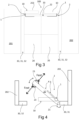
- the control unit 103 in the second mode is configured to detect any external force (denoted Fext in figs. 4 to 8 as a dashed double arrow visualising that the external force may urge the door leaf in any direction, e.g. by pulling or pushing on the handle 23 of figs. 4 and 6 or directly on any side of the door leaf 20 as in figs. 5 , 7 and 8 ) urging the swing door leaf 20 in any direction, and in response to this detection is configured to control the drive unit 100 to operate the motor 101 to counteract the biasing force of the spring 102 as long as the external force is impacting or affecting the swing door leaf, i.e.
- the drive unit 100 still operate the motor 101 to counteract the biasing force of the spring 102 to create the free swing mode of the door leaf 20 while still achieving the automatic mode if any sensor 106 detects that a pedestrian pushes a button to open the swing door 20 automatically without manually pushing the swing door leaf with an external force Fext.
- the swing door leaf 20 could be in any position after being moved manually by a pedestrian into that position, e.g. the swing door leaf 20 could be manually opened in its free swing mode by being pushed by a pedestrian with an external force Fext until a certain angle ⁇ is of door opening is achieved (see figs.
- a sensor 106 detects an input from a button or light detector that the swing door leaf is to be opened or closed.
- the control unit 103 comprises at least one memory 104 and the swing door operator 10 comprises one or more sensors 106 preferably operatively connected to the user interface 105, wherein preferably the control unit is operatively connected to the user interface, the drive unit 100 and/or at least one sensor to be able to control the drive unit in response to input in the user interface and/or signals from the sensor, so that the drive unit is able to move the swing door leaf 20 in accordance with the user interface input and/or signals from the sensor autonomously between the open and closed position in the second mode of the control unit.
- the swing door operator 10 comprises the control unit 103 in its second mode being adapted to control the motor 101 in response to detection of any external force Fext urging the swing door leaf 20 in any direction, whereby the motor is operated to counteract only the biasing force of the spring 102 when any external force is impacting or affecting the swing door leaf.
- the detection and/or measurement and registering of the force and/or torque of the motor 101 required to bias the spring 102, while moving the swing door leaf 20 without the swing door leaf being affected by any external force Fext, in its memory 104 is achieved in cooperation with at least one internal and/or external sensor 106.
- the at least one internal and/or external sensor 106 is at least one built-in sensor of the motor 101.
- the first mode of the control unit 103 is initiated via the user interface 105 to set up the door operator 10
- the second mode of the control unit is initiated via the user interface after completion of the first mode.
- the first mode may be utilized as a predefined standard mode of operation which is set up by the service personnel upon installing the swing door operator.
- the second mode may thus be possible to set up by the end user.
- the user requirements may vary greatly depending on the environement wherein the swing door operator is installed, whereby having the second mode being able to be set up by the end user is particularly advantegous.
- a swing door operator which is easier to adapt to user requirements is achieved.
- the second mode of the control unit 103 is configured to initiate and/or activate and perform autonomous operation of the door operator 10 in cooperation with at least one sensor 106.
- the control unit 103 in its first mode is adapted to regulate the drive unit 100 to operate the motor 101 to swing the swing door leaf 20 in one direction without the swing door leaf being urged in any direction by means of the external force Fext while the spring 102 is biased, and, at the same time, is adapted to detect/measure and register the force and/or torque of the motor required to bias the spring 102 while swinging the swing door leaf 20 without the swing door leaf being impacted or affected by the external force, in its memory 104.
- the motor 101 is an electric motor.
- the drive unit 100 is arranged to apply different trajectories based on how the swing door operator 10 is mounted in relation to the door leaf 20.
- the control unit 103 is according to some aspects connected to different sensors 106 and auxiliary systems (not shown) and arranged to control the drive units 100 based on received information from the sensors and systems.
- the control unit 103 is connected to an alarm system.
- the control unit 103 is connected to a fire alarm system.
- the swing door leaf 20 comprises at least one handle 23. In another aspect, the swing door leaf 20 comprises two handles 23, see figs. 4 and 6 . In yet one aspect, the swing door leaf 20 comprises at least one handle 23 at each of its sides, see figs. 4 and 6 , but could also only have one handle on one side.
- the placement of the handle/-s 23 depend on the specific application and need of a pedestrian, but the major advantage is that the door leaf 20 thereby is easier to move in its free swing mode, and the position of the handle 23 also depends on in which direction the door leaf 20 is possible to move, however, the external force Fext exerted by a pedestrian is then also easier to transfer via a handle 23 if the door leaf is pulled towards the pedestrian, while it is easy to push the door leaf 20 without a handle.
- the swing door operator 10 of figs. 4 , 5 and 7 is a pull swing door operator.
- the swing door operator 10 is connected to a first side of the door leaf 20 and mounted on a first wall side 201, however, in other aspects (not shown in fig's 4, 5, and 6 but in figs. 3 , 7, and 8 for the double swing door version), the swing door operator 10 is connected to a second side of the door leaf 20 and/or mounted on a second wall side 202.
- the arm system 2 of the pull swing door operator 10 is according to an aspect a pull arm system 2, as disclosed in fig. 4 , 5 , and 7 .
- the arm system 2 is in one end connected to the rotary axle 1.
- the arm system 2 is in its other end connected to the door leaf 20.
- the pull arm system 2 comprises an arm 3 and an arm guide 4.
- the arm 3 is in one end connected to the axle 1.
- the arm 3 is in the other end slidably connected to the arm guide 4.
- the arm guide 4 is mounted to the first side of the door leaf 20 facing the door operator 10.
- the arm guide 4 is mounted on the first side of the door leaf 20 and as the arm 3 moves the arm guide 4 of the lonely door operator 10 exert a force on the door leaf 20 (this force from the arm 3 is not the external force Fext).
- the axle 1 When the axle 1 is rotated in the opposite direction, it will move the guide arm 4 and the door leaf 20 in the opposite direction.
- the pull arm system 2 moves the door leaf 20 from the closed position to the open position and from the open position to the closed position.
- the length of the arm 3 and the arm guide 4 and the position of the arm guide 4 on the door leaf 2 are set in relation to the position of the swing door operator 10 in relation to the door leaf 20 and the geometry of the door leaf 20 and the placement of the wall 201.
- the bent arrows at the hinge 21 and the end or edge of the door leaf 20 opposite the edge being mounted to the hinge, i.e. the part of the door leaf that is furthest away from the door operator 10 visualises the movement of the door leaf 20 about the hinge both when moved in its free swing mode but also in its normal mode, i.e. the automatic mode.
- the swing door operator 10 in figs. 6 and 8 is according to an aspect a push swing door operator 10.
- the swing door operator 10 is according to an aspect connected to a first side or a second side of the door leaf 20 (here the first side) and mounted on a first 201 or a second side 202 of the wall (see also the pull version of figs. 4 , 5 and 7 ).
- the arm system 2 of the push swing door operator 10 is according to an aspect a push arm system 2, as disclosed in fig. 6 and 8 .
- the arm system 2 is in one end connected to the axle 1.
- the arm system 2 is in its other end connected to the first or second side of the door leaf 20.
- the second side is opposite to the first side of the door leaf 20.
- the pull arm system 2 comprises a first arm 3A and a second arm 3B.
- the first arm 3A is in one end connected to the axle 1.
- the drive unit 100 i.e. motor 101 and/or the spring 102
- the first arm 3A rotates together with the axle 1.
- the first arm 3A is in the other end rotatable connected to an end of the second arm 3B.
- the second arm 3B is in the other end rotatable connected to the door leaf 20.
- the first arm 3A rotates together with the axle 1.
- the first arm 3A pushes the second arm 3B to move.
- the second arm 3B is moved by the first arm 3A, it exerts a force on the door leaf 20 (this force from the arms 3A, 3B is not the external force Fext) and pushes on the door leaf 20.
- the second arm 3B is rotated in relation to the first arm 3A and the door leaf 20.
- the axle 1 is rotated in the opposite direction by the drive unit 100 it will move the first arm 3A, the second arm 3B and the door leaf 20 in the opposite direction.
- the push door operator 10 moves the door leaf 20 from the closed position to the open position and from the open position to the closed position.
- the length of the first arm 3A and the second arm 3B and the position of where the second arm 3B is connected to the first (or in some aspects the second) side of the door leaf 20 are set in relation to the position of the push swing door operator 10 in relation to the door leaf 20 and the geometry of the door leaf 20 and the placement of the door operator 10 on the wall 201.
- a method is used for setup and then operation of the swing door operator 10 for moving at least one swing door leaf 20 between an open position and a closed position.
- the swing door operator 10 for moving a swing door leaf 20 relative a door frame 30 or one or more other swing door leafs 20 or swing door leaf sections and/or between an open and closed position and/or into any other position comprises at least one drive unit 100 that comprises at least one motor 101 and at least one spring 102.
- the motor 101 and spring 102 interact to enable moving the swing door leaf 20 being hingedly connected to the door frame 30.
- the door operator 10 further comprises an user interface 105 and at least one sensor 106 operatively connected to at least one control unit 103 and the swing door leaf 20, whereby the sensor 106 is configured to detect if any external force Fext, e.g. from a pedestrian trying to move the swing door leaf 20, is applied onto the swing door leaf.
- the control unit 103 is thereby able to control the motor 101 for swinging the swing door leaf 20 in response to detection by the sensor 106 and comprises a memory 104.
- One aspect of the method uses the registered force of the spring 102 determined in the set up mode to control the swing door operator 10 in the second mode of operation such that if it is detected by the sensor 106 that any external force Fext is applied to the swing door leaf 20, the swing door leaf moves in response to the external force as if in free swing mode.
- operation of the drive unit 100 drives the motor 101 so that it moves the swing door leaf 20 biasing the spring 102, which function is used in the set up mode to determine the spring force in the spring.
- the determination of the spring force in the spring 102 is done by measuring the force/torque of the motor 101 and using the characteristics of the motor (gearing and torque constant) and the characteristics of the spring to calculate the spring force at different positions of the door leaf.
- control unit 103 in the second mode, regulate the motor 101 of the drive unite 100 to counteract the force of the spring 102 by exerting a force on the swing door leaf 20 that is equal to in size and opposite to in direction to the biasing force of the spring.
- control unit 103 in the second mode is set to detect any external force Fext urging the swing door leaf 20 in any direction, and in response to detection of an external force controls the drive unit 100 to operate the motor 101 to counteract the biasing force of the spring 102 as long as the external force is affecting the swing door leaf.
- control unit 103 in its second mode controls the motor 101 in response to detection of any external force Fext urging the swing door leaf 20 in any direction, such that the motor counteract only the biasing force of the spring 102 when any external force is impacting/affecting the swing door leaf.
- the detection and/or measurement and registering of the force/torque of the motor 101 required to bias the spring 102, while moving the swing door leaf 20 without the swing door leaf being affected by any external force Fext, in its memory 104 is achieved in cooperation with at least one internal and/or external sensor 106.
- a swing door set may comprise of more than two swinging door leafs, arranged in the same way as discussed above, e.g. hinged to the left or the right or at its upper or lower side if the door leaf is shaped as a parallelepiped and/or is to swing around/about an axis being vertical or horizontal and/or the swing door leafs, if more than one is used, could have different dimensions and/or shapes.
Landscapes
- Power-Operated Mechanisms For Wings (AREA)
Claims (11)
- Schwingtürbetätiger (10) zum Bewegen eines Schwingtürblatts (20) zwischen einer offenen und einer geschlossenen Position, wobei der Schwingtürbetätiger (10) mindestens eine Antriebseinheit (100) umfasst, die mindestens einen Motor (101) und mindestens eine Feder (102) umfasst, wobei der Motor (101) und die Feder (102) dazu angeordnet sind, zu interagieren, um es zu ermöglichen, das Schwingtürblatt (10) zwischen der offenen und geschlossenen Position zu bewegen, wobei der Schwingtürbetätiger (10) ferner eine Steuereinheit (103) umfasst, die mit der Antriebseinheit (100) und dem Motor (101) wirkverbunden ist, wobei die Steuereinheit (103) einen Speicher (104) umfasst und der Schwingtürbetätiger (10) ferner mindestens einen internen und/oder externen Sensor (106) und eine Benutzerschnittstelle (105) umfasst,wobei die Steuereinheit (103) mit einem Einrichtungsmodus des Schwingtürbetätigers (10) angepasst ist, der über die Benutzerschnittstelle (105) initiiert werden kann, wobei der mindestens eine interne und/oder externe Sensor (106) im Einrichtungsmodus zur Detektion und/oder Messung und Aufzeichnung einer Kraft und/oder eines Drehmoments des Motors (101) in dem Speicher angepasst sind/ist, die/das erforderlich sind/ist, um die Feder (102) vorzuspannen, während der Motor (101) angetrieben und das Schwingtürblatt (20) bewegt wird, ohne dass sich eine jegliche externe Kraft (Fext) auf das Schwingtürblatt (20) auswirkt,wobei die Steuereinheit (103):- in einem ersten Modus dazu konfiguriert ist, die Antriebseinheit (100) zu regulieren, um das Schwingtürblatt (20) zwischen der offenen und geschlossenen Position zu bewegen, und- in einem zweiten Modus dazu konfiguriert ist, den Motor (101) der Antriebseinheit (100) unter Verwendung der aufgezeichneten Kraft der Feder (102), die in dem Einrichtungsmodus bestimmt wurde, zu steuern, um der Kraft der Feder (102) entgegenzuwirken, sodass das Schwingtürblatt (20) dazu konfiguriert ist, in einem Modus des freien Schwingens bewegt zu werden.
- Schwingtürbetätiger (10) nach Anspruch 1, wobei die Steuereinheit (103) dazu konfiguriert ist, in dem zweiten Modus den Motor (101) der Antriebseinheit (100) zu regulieren, um der Kraft der Feder (102) entgegenzuwirken, indem eine Kraft auf das Schwingtürblatt (20) ausgeübt wird, dessen Betrag gleich der Vorspannkraft der Feder (102) ist und deren Richtung dieser entgegengesetzt ist.
- Schwingtürbetätiger (10) nach Anspruch 1 oder 2, wobei die Steuereinheit (103) in dem zweiten Modus dazu konfiguriert ist, eine jegliche externe Kraft (Fext) zu detektieren, die das Schwingtürblatt (20) in eine beliebige Richtung drückt, und als Reaktion auf diese Detektion dazu konfiguriert ist, die Antriebseinheit (100) zu steuern, um den Motor (101) zu betreiben, um der Vorspannkraft der Feder (102) entgegenzuwirken, zumindest solange sich die externe Kraft auf das Schwingtürblatt (20) auswirkt.
- Schwingtürbetätiger (10) nach einem der vorhergehenden Ansprüche, wobei die Steuereinheit (103) mit der Benutzerschnittstelle (105), der Antriebseinheit (100) und/oder dem mindestens einen Sensor (106) wirkverbunden ist, um die Antriebseinheit (100) als Reaktion auf eine Eingabe in die Benutzerschnittstelle (105) und/oder auf Signale von dem Sensor (106) zu steuern, sodass der Motor (101) in dem zweiten Modus der Steuereinheit (100) dazu in der Lage ist, der Kraft von der Feder (102) entsprechend der Benutzerschnittstelleneingabe und/oder den Signalen von dem Sensor autonom zwischen der offenen und geschlossenen Position entgegenzuwirken.
- Schwingtürbetätiger (10) nach einem der vorhergehenden Ansprüche, wobei die Steuereinheit (103) in ihrem zweiten Modus dazu angepasst ist, den Motor (101) als Reaktion auf eine Detektion einer jeglichen externen Kraft (Fext), die das Schwingtürblatt (20) in eine beliebige Richtung drückt, zu steuern, wodurch der Motor betrieben wird, um nur dann der Vorspannkraft der Feder (102) entgegenzuwirken, wenn eine jegliche externe Kraft das Schwingtürblatt beeinträchtigt und/oder sich auf dieses auswirkt.
- Schwingtürbetätiger (10) nach Anspruch 4 oder Anspruch 5 bei Abhängigkeit von Anspruch 4, wobei die Detektion und/oder Messung und Aufzeichnung der Kraft und/oder des Drehmoments des Motors (101) in seinem Speicher (104), die/das erforderlich sind/ist, um die Feder (102) vorzuspannen, während das Schwingtürblatt (20) betätigt wird, ohne dass sich eine jegliche externe Kraft (Fext) auf das Schwingtürblatt auswirkt, dadurch erreicht werden, dass der mindestens eine interne und/oder externe Sensor (106) den durch den Motor (101) bezogenen Strom misst.
- Schwingtürbetätiger (10) nach Anspruch 6, wobei der mindestens eine interne und/oder externe Sensor (106) mindestens ein eingebauter Sensor des Motors (101) ist.
- Schwingtürbetätiger (10) nach Anspruch 4 oder einem der Ansprüche 5 bis 7 bei Abhängigkeit von Anspruch 4, wobei der erste Modus der Steuereinheit (103) über die Benutzerschnittstelle (105) initiiert werden kann, um den Türbetätiger (10) einzurichten, und der zweite Modus der Steuereinheit nach Abschluss des ersten Modus über die Benutzerschnittstelle initiiert werden kann.
- Schwingtürbetätiger (10) nach Anspruch 4 oder einem der Ansprüche 5 bis 8 bei Abhängigkeit von Anspruch 4, wobei der zweite Modus der Steuereinheit (103) dazu konfiguriert ist, eine autonome Betätigung des Türbetätigers (10) in Zusammenwirkung mit mindestens einem Sensor (106) zu initiieren und/oder zu aktivieren und durchzuführen.
- Schwingtürbetätiger (10) nach einem der vorhergehenden Ansprüche, wobei die Steuereinheit (103) in ihrem ersten Modus dazu angepasst ist, die Antriebseinheit (100) zu regulieren, um den Motor (101) zu betreiben, um das Schwingtürblatt (20) in eine Richtung schwingen zu lassen, ohne dass das Schwingtürblatt mithilfe einer externen Kraft (Fext) in eine jegliche Richtung gedrückt wird, während die Feder (102) vorgespannt wird, und gleichzeitig dazu angepasst ist, die Kraft und/oder das Drehmoment des Motors zu detektieren und/oder zu messen und in ihrem Speicher (104) aufzuzeichnen, die/das erforderlich sind/ist, um die Feder vorzuspannen, während das Schwingtürblatt schwingen gelassen wird, ohne dass eine jegliche Kraft das Schwingtürblatt beeinträchtigt und/oder sich auf dieses auswirkt.
- Schwingtürbetätiger (10) nach einem der vorangehenden Ansprüche, wobei der Motor (101) ein Elektromotor ist.
Applications Claiming Priority (2)
| Application Number | Priority Date | Filing Date | Title |
|---|---|---|---|
| SE1830237 | 2018-08-09 | ||
| PCT/EP2019/071289 WO2020030728A1 (en) | 2018-08-09 | 2019-08-08 | Door operator and method of its operation |
Publications (3)
| Publication Number | Publication Date |
|---|---|
| EP3833838A1 EP3833838A1 (de) | 2021-06-16 |
| EP3833838C0 EP3833838C0 (de) | 2024-08-21 |
| EP3833838B1 true EP3833838B1 (de) | 2024-08-21 |
Family
ID=67659837
Family Applications (1)
| Application Number | Title | Priority Date | Filing Date |
|---|---|---|---|
| EP19753307.8A Active EP3833838B1 (de) | 2018-08-09 | 2019-08-08 | Türbetätiger und verfahren zu dessen betrieb |
Country Status (4)
| Country | Link |
|---|---|
| US (1) | US11536075B2 (de) |
| EP (1) | EP3833838B1 (de) |
| CA (1) | CA3106290A1 (de) |
| WO (1) | WO2020030728A1 (de) |
Families Citing this family (7)
| Publication number | Priority date | Publication date | Assignee | Title |
|---|---|---|---|---|
| CN113825886B (zh) * | 2019-05-13 | 2024-01-02 | 亚萨合莱自动门系统有限公司 | 用于在开启位置和关闭位置之间的摆动路径上移动摆动门扇的摆动门操作器、摆动门及具有摆动门的房间 |
| WO2020249456A1 (en) * | 2019-06-13 | 2020-12-17 | Assa Abloy Entrance Systems Ab | Swing door operator operable in powered and powerless mode |
| US12006754B2 (en) * | 2019-06-13 | 2024-06-11 | Assa Abloy Entrance Systems Ab | Method for testing a door operator |
| WO2020254142A1 (en) * | 2019-06-17 | 2020-12-24 | Assa Abloy Entrance Systems Ab | Swing door-based entrance system with improved operability in emergency mode |
| KR102521286B1 (ko) * | 2020-09-08 | 2023-04-13 | 엘지전자 주식회사 | 투명 디스플레이를 이용하여 자동문을 구현하는 시스템 |
| US20240125166A1 (en) * | 2021-02-24 | 2024-04-18 | Dormakaba Deutschland Gmbh | Door system for one or more doors |
| US12595700B2 (en) | 2024-01-02 | 2026-04-07 | Schlage Lock Company Llc | Method and apparatus for adjusting the opening speed and torque of a door with a door operator |
Citations (6)
| Publication number | Priority date | Publication date | Assignee | Title |
|---|---|---|---|---|
| DE102005001328A1 (de) | 2005-01-11 | 2006-07-20 | Dorma Gmbh + Co. Kg | Verfahren zum Betreiben eines Drehtürantriebes |
| DE102006062333A1 (de) | 2006-12-22 | 2008-06-26 | Geze Gmbh | Türantrieb |
| US20090265992A1 (en) | 2005-04-13 | 2009-10-29 | Brian Hass | Door Operator for Controlling a Door and Method of Same |
| US20110252597A1 (en) | 2010-04-16 | 2011-10-20 | Yale Security Inc. | Self-adjusting door closer |
| US9617776B2 (en) | 2010-03-31 | 2017-04-11 | Veritas Medical Solutions Llc | Motor driven door assembly |
| EP3196392A1 (de) | 2016-01-19 | 2017-07-26 | GEZE GmbH | Elektromotorischer antrieb mit schliessfeder |
Family Cites Families (19)
| Publication number | Priority date | Publication date | Assignee | Title |
|---|---|---|---|---|
| US4222147A (en) | 1978-03-20 | 1980-09-16 | Reading Door Closer Corp. | Door closer with assist or door operating features |
| US4339843A (en) | 1978-03-20 | 1982-07-20 | Reading-Dorma Closer Corporation | Door closer with assist or door operating features |
| US4952080A (en) | 1989-05-12 | 1990-08-28 | The Stanley Works | Automatic assist for swing-door operator |
| CA2124403C (en) | 1993-07-19 | 2001-12-18 | Mark A. Beran | Apparatus and method for selective alteration of operating parameters of a door |
| US5956249A (en) | 1993-07-19 | 1999-09-21 | Dorma Door Controls Inc. | Method for electromechanical control of the operational parameters of a door in conjunction with a mechanical door control mechanism |
| US5878530A (en) * | 1994-10-18 | 1999-03-09 | Eccleston Mechanical | Remotely controllable automatic door operator permitting active and passive door operation |
| US8225458B1 (en) * | 2001-07-13 | 2012-07-24 | Hoffberg Steven M | Intelligent door restraint |
| US6891479B1 (en) * | 2003-06-12 | 2005-05-10 | Jon E. Eccleston | Remotely controllable automatic door operator and closer |
| US7316096B2 (en) * | 2004-06-30 | 2008-01-08 | Yale Security Inc. | Door operator |
| CA2543592C (en) * | 2005-04-13 | 2013-06-25 | Brian Hass | Door operator assembly |
| US8261491B2 (en) * | 2008-04-02 | 2012-09-11 | Leon Yulkowski | Concealed electrical door operator |
| US8407937B2 (en) * | 2009-10-22 | 2013-04-02 | Yale Security Inc. | Door operator |
| US20160060941A1 (en) * | 2014-09-03 | 2016-03-03 | Wesley G. Ingham | Coaxially Extending Arm for Door Closing Operator |
| WO2016156108A1 (en) * | 2015-03-31 | 2016-10-06 | Assa Abloy Entrance Systems Ab | Method of operating a swing door, device for operating a swing door and a swing door operated by such a method and/or having such a device |
| DE102016202225A1 (de) * | 2016-02-15 | 2017-08-17 | Geze Gmbh | Bremsvorrichtung für einen beweglichen Türflügel und korrespondierender Türschließer |
| US10208520B2 (en) * | 2016-05-16 | 2019-02-19 | Schlage Lock Company Llc | Method and apparatus for adjusting the closing force of a door |
| US10099629B2 (en) * | 2016-09-06 | 2018-10-16 | Huf North America Automotive Parts Manufacturing Corp. | Deployable sensor assembly |
| RU2754751C2 (ru) * | 2016-12-07 | 2021-09-07 | Асса Аблой Энтранс Системс АБ | Автоматический открыватель двери для распашной двери в сборе |
| DE102017201957B4 (de) * | 2017-02-08 | 2024-12-12 | Geze Gmbh | Antriebseinheit zum Schließen eines Flügels einer Tür oder eines Fensters |
-
2019
- 2019-08-08 CA CA3106290A patent/CA3106290A1/en active Pending
- 2019-08-08 EP EP19753307.8A patent/EP3833838B1/de active Active
- 2019-08-08 WO PCT/EP2019/071289 patent/WO2020030728A1/en not_active Ceased
- 2019-08-08 US US17/259,865 patent/US11536075B2/en active Active
Patent Citations (6)
| Publication number | Priority date | Publication date | Assignee | Title |
|---|---|---|---|---|
| DE102005001328A1 (de) | 2005-01-11 | 2006-07-20 | Dorma Gmbh + Co. Kg | Verfahren zum Betreiben eines Drehtürantriebes |
| US20090265992A1 (en) | 2005-04-13 | 2009-10-29 | Brian Hass | Door Operator for Controlling a Door and Method of Same |
| DE102006062333A1 (de) | 2006-12-22 | 2008-06-26 | Geze Gmbh | Türantrieb |
| US9617776B2 (en) | 2010-03-31 | 2017-04-11 | Veritas Medical Solutions Llc | Motor driven door assembly |
| US20110252597A1 (en) | 2010-04-16 | 2011-10-20 | Yale Security Inc. | Self-adjusting door closer |
| EP3196392A1 (de) | 2016-01-19 | 2017-07-26 | GEZE GmbH | Elektromotorischer antrieb mit schliessfeder |
Non-Patent Citations (6)
| Title |
|---|
| D7A - SLIMDRIVE - DE ANSCHLUSSPLAN, VERSION 167781-00 (DATE?) |
| D7B - LIEFERSCHEIN HERBERT WALTHER GMBH & CO. KG |
| D7C - RECHNUNG HERBERT WALTHER GMBH & CO. KG |
| D7D - LIEFERSCHEIN SCHULER PRESSEN GMBH |
| D7E - RECHNUNG SCHULER PRESSEN GMBH |
| D7F - EIDESSTATTLICHE VERSICHERUNG EUGEN KATZ |
Also Published As
| Publication number | Publication date |
|---|---|
| US20210222476A1 (en) | 2021-07-22 |
| EP3833838C0 (de) | 2024-08-21 |
| US11536075B2 (en) | 2022-12-27 |
| CA3106290A1 (en) | 2020-02-13 |
| EP3833838A1 (de) | 2021-06-16 |
| WO2020030728A1 (en) | 2020-02-13 |
Similar Documents
| Publication | Publication Date | Title |
|---|---|---|
| EP3833838B1 (de) | Türbetätiger und verfahren zu dessen betrieb | |
| EP3963166B1 (de) | Schwingtürbasiertes eingangssystem mit automatischer erkennung der verbindungsreduktionskurve | |
| CA2400129C (en) | Method and device for setting custom door travel limits on a motorized garage door operator | |
| US8844200B2 (en) | Electrical door operator | |
| CN102470735B (zh) | 用于识别翻盖驱动装置中接合器的触发的方法和装置 | |
| EP1304442A2 (de) | Verfahren und Vorrichtung zur Erhöhung der zugelassenen Motorleistung eines Garagentorantriebs | |
| EP2924209B1 (de) | Zu öffnendes Dachfenster mit aktivem Schloss | |
| EP3615753B1 (de) | Schwingtürbetätigungsanordnung | |
| US7116072B1 (en) | Motorized barrier operator system for setting a down force adjustment to a minimum value and method for programming the same | |
| EP3475512B1 (de) | Türbetätiger und verfahren zur einstellung eines türbetätigers | |
| US11697960B2 (en) | Parallel operation of door operators | |
| EP3464769B1 (de) | Schwingtürbetätiger | |
| EP3475511B1 (de) | Verfahren zum einrichten eines türbetätigers und türbetätiger | |
| EP3604720B1 (de) | Motorisiertes verschlusssystem und verfahren | |
| AU2020276047B2 (en) | A swing door operator for moving a swing door leaf between a closed and an open position, a swing door system and a method of regulating a swing door operator for moving a swing door leaf between a closed and an open position | |
| KR101709954B1 (ko) | 스마트 자동문 제어장치 | |
| JP2011084916A (ja) | 半自動引き戸 | |
| KR20260063945A (ko) | 여닫이 문을 위한 지능형 전동식 개폐 장치 | |
| WO2017211758A1 (en) | Door operator | |
| HK1055454A (en) | Method and device for setting custom door travel limits on a motorized garage door operator |
Legal Events
| Date | Code | Title | Description |
|---|---|---|---|
| STAA | Information on the status of an ep patent application or granted ep patent |
Free format text: STATUS: UNKNOWN |
|
| STAA | Information on the status of an ep patent application or granted ep patent |
Free format text: STATUS: THE INTERNATIONAL PUBLICATION HAS BEEN MADE |
|
| PUAI | Public reference made under article 153(3) epc to a published international application that has entered the european phase |
Free format text: ORIGINAL CODE: 0009012 |
|
| STAA | Information on the status of an ep patent application or granted ep patent |
Free format text: STATUS: REQUEST FOR EXAMINATION WAS MADE |
|
| 17P | Request for examination filed |
Effective date: 20210127 |
|
| AK | Designated contracting states |
Kind code of ref document: A1 Designated state(s): AL AT BE BG CH CY CZ DE DK EE ES FI FR GB GR HR HU IE IS IT LI LT LU LV MC MK MT NL NO PL PT RO RS SE SI SK SM TR |
|
| RIN1 | Information on inventor provided before grant (corrected) |
Inventor name: SOEDERQVIST, SVEN-GUNNAR |
|
| DAV | Request for validation of the european patent (deleted) | ||
| DAX | Request for extension of the european patent (deleted) | ||
| STAA | Information on the status of an ep patent application or granted ep patent |
Free format text: STATUS: EXAMINATION IS IN PROGRESS |
|
| 17Q | First examination report despatched |
Effective date: 20230926 |
|
| GRAP | Despatch of communication of intention to grant a patent |
Free format text: ORIGINAL CODE: EPIDOSNIGR1 |
|
| STAA | Information on the status of an ep patent application or granted ep patent |
Free format text: STATUS: GRANT OF PATENT IS INTENDED |
|
| INTG | Intention to grant announced |
Effective date: 20240402 |
|
| GRAS | Grant fee paid |
Free format text: ORIGINAL CODE: EPIDOSNIGR3 |
|
| GRAA | (expected) grant |
Free format text: ORIGINAL CODE: 0009210 |
|
| STAA | Information on the status of an ep patent application or granted ep patent |
Free format text: STATUS: THE PATENT HAS BEEN GRANTED |
|
| AK | Designated contracting states |
Kind code of ref document: B1 Designated state(s): AL AT BE BG CH CY CZ DE DK EE ES FI FR GB GR HR HU IE IS IT LI LT LU LV MC MK MT NL NO PL PT RO RS SE SI SK SM TR |
|
| REG | Reference to a national code |
Ref country code: GB Ref legal event code: FG4D |
|
| REG | Reference to a national code |
Ref country code: CH Ref legal event code: EP |
|
| REG | Reference to a national code |
Ref country code: IE Ref legal event code: FG4D |
|
| REG | Reference to a national code |
Ref country code: DE Ref legal event code: R096 Ref document number: 602019057416 Country of ref document: DE |
|
| U01 | Request for unitary effect filed |
Effective date: 20240903 |
|
| U07 | Unitary effect registered |
Designated state(s): AT BE BG DE DK EE FI FR IT LT LU LV MT NL PT RO SE SI Effective date: 20240917 |
|
| PG25 | Lapsed in a contracting state [announced via postgrant information from national office to epo] |
Ref country code: NO Free format text: LAPSE BECAUSE OF FAILURE TO SUBMIT A TRANSLATION OF THE DESCRIPTION OR TO PAY THE FEE WITHIN THE PRESCRIBED TIME-LIMIT Effective date: 20241121 |
|
| PG25 | Lapsed in a contracting state [announced via postgrant information from national office to epo] |
Ref country code: GR Free format text: LAPSE BECAUSE OF FAILURE TO SUBMIT A TRANSLATION OF THE DESCRIPTION OR TO PAY THE FEE WITHIN THE PRESCRIBED TIME-LIMIT Effective date: 20241122 Ref country code: PL Free format text: LAPSE BECAUSE OF FAILURE TO SUBMIT A TRANSLATION OF THE DESCRIPTION OR TO PAY THE FEE WITHIN THE PRESCRIBED TIME-LIMIT Effective date: 20240821 |
|
| PG25 | Lapsed in a contracting state [announced via postgrant information from national office to epo] |
Ref country code: IS Free format text: LAPSE BECAUSE OF FAILURE TO SUBMIT A TRANSLATION OF THE DESCRIPTION OR TO PAY THE FEE WITHIN THE PRESCRIBED TIME-LIMIT Effective date: 20241221 |
|
| PG25 | Lapsed in a contracting state [announced via postgrant information from national office to epo] |
Ref country code: HR Free format text: LAPSE BECAUSE OF FAILURE TO SUBMIT A TRANSLATION OF THE DESCRIPTION OR TO PAY THE FEE WITHIN THE PRESCRIBED TIME-LIMIT Effective date: 20240821 |
|
| PG25 | Lapsed in a contracting state [announced via postgrant information from national office to epo] |
Ref country code: ES Free format text: LAPSE BECAUSE OF FAILURE TO SUBMIT A TRANSLATION OF THE DESCRIPTION OR TO PAY THE FEE WITHIN THE PRESCRIBED TIME-LIMIT Effective date: 20240821 Ref country code: RS Free format text: LAPSE BECAUSE OF FAILURE TO SUBMIT A TRANSLATION OF THE DESCRIPTION OR TO PAY THE FEE WITHIN THE PRESCRIBED TIME-LIMIT Effective date: 20241121 |
|
| PG25 | Lapsed in a contracting state [announced via postgrant information from national office to epo] |
Ref country code: RS Free format text: LAPSE BECAUSE OF FAILURE TO SUBMIT A TRANSLATION OF THE DESCRIPTION OR TO PAY THE FEE WITHIN THE PRESCRIBED TIME-LIMIT Effective date: 20241121 Ref country code: PL Free format text: LAPSE BECAUSE OF FAILURE TO SUBMIT A TRANSLATION OF THE DESCRIPTION OR TO PAY THE FEE WITHIN THE PRESCRIBED TIME-LIMIT Effective date: 20240821 Ref country code: NO Free format text: LAPSE BECAUSE OF FAILURE TO SUBMIT A TRANSLATION OF THE DESCRIPTION OR TO PAY THE FEE WITHIN THE PRESCRIBED TIME-LIMIT Effective date: 20241121 Ref country code: IS Free format text: LAPSE BECAUSE OF FAILURE TO SUBMIT A TRANSLATION OF THE DESCRIPTION OR TO PAY THE FEE WITHIN THE PRESCRIBED TIME-LIMIT Effective date: 20241221 Ref country code: HR Free format text: LAPSE BECAUSE OF FAILURE TO SUBMIT A TRANSLATION OF THE DESCRIPTION OR TO PAY THE FEE WITHIN THE PRESCRIBED TIME-LIMIT Effective date: 20240821 Ref country code: GR Free format text: LAPSE BECAUSE OF FAILURE TO SUBMIT A TRANSLATION OF THE DESCRIPTION OR TO PAY THE FEE WITHIN THE PRESCRIBED TIME-LIMIT Effective date: 20241122 Ref country code: ES Free format text: LAPSE BECAUSE OF FAILURE TO SUBMIT A TRANSLATION OF THE DESCRIPTION OR TO PAY THE FEE WITHIN THE PRESCRIBED TIME-LIMIT Effective date: 20240821 |
|
| PG25 | Lapsed in a contracting state [announced via postgrant information from national office to epo] |
Ref country code: SM Free format text: LAPSE BECAUSE OF FAILURE TO SUBMIT A TRANSLATION OF THE DESCRIPTION OR TO PAY THE FEE WITHIN THE PRESCRIBED TIME-LIMIT Effective date: 20240821 |
|
| PG25 | Lapsed in a contracting state [announced via postgrant information from national office to epo] |
Ref country code: CZ Free format text: LAPSE BECAUSE OF FAILURE TO SUBMIT A TRANSLATION OF THE DESCRIPTION OR TO PAY THE FEE WITHIN THE PRESCRIBED TIME-LIMIT Effective date: 20240821 |
|
| PG25 | Lapsed in a contracting state [announced via postgrant information from national office to epo] |
Ref country code: SK Free format text: LAPSE BECAUSE OF FAILURE TO SUBMIT A TRANSLATION OF THE DESCRIPTION OR TO PAY THE FEE WITHIN THE PRESCRIBED TIME-LIMIT Effective date: 20240821 |
|
| PLBI | Opposition filed |
Free format text: ORIGINAL CODE: 0009260 |
|
| PLAF | Information modified related to communication of a notice of opposition and request to file observations + time limit |
Free format text: ORIGINAL CODE: EPIDOSCOBS2 |
|
| PLAX | Notice of opposition and request to file observation + time limit sent |
Free format text: ORIGINAL CODE: EPIDOSNOBS2 |
|
| 26 | Opposition filed |
Opponent name: GEZE GMBH Effective date: 20250521 |
|
| U20 | Renewal fee for the european patent with unitary effect paid |
Year of fee payment: 7 Effective date: 20250723 |
|
| PLBB | Reply of patent proprietor to notice(s) of opposition received |
Free format text: ORIGINAL CODE: EPIDOSNOBS3 |
|
| PGFP | Annual fee paid to national office [announced via postgrant information from national office to epo] |
Ref country code: GB Payment date: 20250710 Year of fee payment: 7 |
|
| REG | Reference to a national code |
Ref country code: CH Ref legal event code: H13 Free format text: ST27 STATUS EVENT CODE: U-0-0-H10-H13 (AS PROVIDED BY THE NATIONAL OFFICE) Effective date: 20260324 |
|
| PG25 | Lapsed in a contracting state [announced via postgrant information from national office to epo] |
Ref country code: MC Free format text: LAPSE BECAUSE OF FAILURE TO SUBMIT A TRANSLATION OF THE DESCRIPTION OR TO PAY THE FEE WITHIN THE PRESCRIBED TIME-LIMIT Effective date: 20240821 |
|
| PG25 | Lapsed in a contracting state [announced via postgrant information from national office to epo] |
Ref country code: CH Free format text: LAPSE BECAUSE OF NON-PAYMENT OF DUE FEES Effective date: 20250831 |