EP3834612A1 - Dispositif et procédé d'application d'un liquide à pulvériser sur une surface agricole - Google Patents
Dispositif et procédé d'application d'un liquide à pulvériser sur une surface agricole Download PDFInfo
- Publication number
- EP3834612A1 EP3834612A1 EP20401064.9A EP20401064A EP3834612A1 EP 3834612 A1 EP3834612 A1 EP 3834612A1 EP 20401064 A EP20401064 A EP 20401064A EP 3834612 A1 EP3834612 A1 EP 3834612A1
- Authority
- EP
- European Patent Office
- Prior art keywords
- nozzle
- spray
- nozzles
- nozzle holder
- holders
- Prior art date
- Legal status (The legal status is an assumption and is not a legal conclusion. Google has not performed a legal analysis and makes no representation as to the accuracy of the status listed.)
- Pending
Links
Images

Classifications
-
- A—HUMAN NECESSITIES
- A01—AGRICULTURE; FORESTRY; ANIMAL HUSBANDRY; HUNTING; TRAPPING; FISHING
- A01M—CATCHING, TRAPPING OR SCARING OF ANIMALS; APPARATUS FOR THE DESTRUCTION OF NOXIOUS ANIMALS OR NOXIOUS PLANTS
- A01M7/00—Special adaptations or arrangements of liquid-spraying apparatus for purposes covered by this subclass
- A01M7/0089—Regulating or controlling systems
Definitions
- the invention relates to a spraying device, in particular an agricultural field sprayer, according to the preamble of claim 1 and a method for operating a spraying device according to the preamble of claim 11.
- Spray devices are used to apply spray liquid containing active ingredient on an agricultural area.
- Spray devices of the generic type, in particular agricultural field sprayers comprise at least one storage container from which the spray liquid can be applied to the agricultural area via at least one supply line and nozzle holders, in particular nozzles, arranged downstream thereof.
- at least some of the supply lines and / or the nozzle holders, in particular nozzles are arranged on a linkage formed from a plurality of sections, preferably essentially transversely to a direction of travel.
- the setting of a demand-based application rate is extremely important in order to achieve good application results on the one hand and good increases in yield on the other.
- nozzle holders designed as multiple nozzle bodies, especially nozzles, and / or pulse-width modulated valves assigned to the nozzle holders, especially nozzles have become established in modern spraying devices .
- Nozzle holders designed as multiple nozzle bodies, in particular nozzles can, in addition to a single nozzle, also have several nozzles, preferably with each have different spray properties.
- the application rate in particular the application rate
- the application rate can be adjusted by controlling and / or activating a single nozzle and / or, preferably a combination, of several nozzles of at least one nozzle holder.
- the nozzle holders arranged within a section have almost the same discharge rates.
- the nozzle holders, in particular nozzles, of at least one part-width, preferably together can be set to a specific application rate and / or can be switched off and / or activated.
- multi-fluid nozzles in particular two-fluid nozzles, are also used.
- a multi-substance nozzle can be supplied with at least one further spray liquid and / or with at least one compressible fluid, in particular compressed air, and can therefore be used more variably than a single-substance nozzle.
- the spray device comprises at least one linkage, which is preferably formed from a plurality of sections connected to one another in an articulated manner, and a plurality of nozzle holders arranged on the linkage.
- the nozzle holders here comprise at least one nozzle, by means of which a spray liquid containing active substance can be applied to an agricultural area.
- the spray device comprises at least one control unit which is set up to activate and / or control the nozzle holder as a function of a speed and / or rotation rate and / or an adjustable target application rate.
- the application rate of a nozzle holder, in particular a nozzle can be regulated by the at least one control unit in such a way that the deviation of the application rate from the target application rate is minimal, preferably zero.
- the nozzle holders are primarily based on the nature of the agricultural Area and / or its plant population, in particular the position of the respective nozzle on the agricultural area, can be activated and / or controlled.
- Each nozzle holder, in particular nozzle, of the spray device can be controlled and / or regulated by means of a control and / or regulating routine of the control system.
- the nozzle holders, in particular nozzles can be assigned to a plurality of, in particular fixed, partial widths, which in particular essentially correspond to the individual sections of the boom, which results in greatly restricted flexibility of the application.
- the range of the application rate is severely limited by the number and / or the spray properties of the nozzles arranged on the nozzle holder. This applies on the one hand to the achievable minimum and / or maximum application rate and on the other hand also to the gradation of the achievable application rates, in particular the applied application rates, along the boom.
- the application of widely differing application rates requires a time-consuming change of the nozzle holders, in particular nozzles, on the boom by an operator.
- nozzle holders in particular nozzles
- only a rough gradation of the application rates, in particular between at least two partial widths, along the boom can lead to underdosing and / or overdosing on the agricultural area and / or its vegetation.
- the limited number of nozzle holders, in particular nozzles is particularly disadvantageous when the spray device is cornering.
- a part of the linkage is at least essentially facing the center of the curve and thus has a lower circumferential speed compared to the part facing away from the center of the curve. It is therefore necessary to vary, in particular to increase, the discharge rates of the nozzle holders, in particular nozzles, along the rod, in particular in the direction of the increasing circumferential speed.
- a wide range of application rates along the boom is extremely important for optimal application of the spray liquid, especially when cornering.
- the object on which the invention is based is thus to design a spraying device, in particular an agricultural field sprayer, in such a way that the above-mentioned disadvantages are at least partially alleviated and / or eliminated.
- this object is achieved in that the nozzle holders, in particular when cornering, can be assigned as a function of at least one parameter, preferably variable, partial widths.
- the amount of spray liquid that can be applied to the agricultural area can be adjusted via a, preferably variable, combination of nozzle holders, in particular nozzles, which are each assigned to a, preferably variable, partial width along the boom.
- Part-widths which include at least two nozzle holders, in particular nozzles, are particularly preferred here.
- the assignment of the respective nozzle holders, in particular nozzles, within the partial widths is temporally spaced, preferably continuously, adaptable within a control and / or regulation routine of the spray device.
- the parameters that can be taken into account for the assignment of the partial widths can be state variables and / or environmental information in the area of the agricultural area that can be detected by at least one sensor.
- the spray properties of the individual and / or combined nozzle holders, in particular nozzles are of decisive importance for determining the preferably variable partial widths.
- these can be taken into account by the control and / or regulating device as an alternative or in addition to determining the section size and / or section distribution along the boom.
- This measure allows a significantly increased flexibility of the application rates along the boom.
- the sections are divided by at least two different speed intervals defined size can be defined.
- the speed of the spray device and / or at least one nozzle holder, in particular a nozzle can be taken into account for assignment to the respective section.
- this can also be understood to mean a circumferential and / or angular speed of a spray device and / or a nozzle holder, in particular a nozzle, which is movable during cornering.
- the spray device By means of the size and / or width of the speed intervals, in particular the sensitivity of a nozzle control and / or nozzle activation can be influenced.
- the spray device reacts less strongly with an adaptation of the application rate than in the case of less large and / or less wide speed intervals.
- the nozzles within a nozzle holder can be activated individually and / or in combination, and the nozzle holders, in particular nozzles, can be controlled taking into account at least one adjacent nozzle holder, in particular nozzle.
- a control and / or regulating device assigned to the spray device is set up to take into account, in particular to compare, the spray properties of at least two adjacent nozzle holders, in particular nozzles, and / or to assign the nozzle holders, in particular nozzles, to the, preferably variable, partial widths.
- the spray liquid can thus be applied by means of the nozzle holders, in particular nozzles, which can be classified within a partial width, at an application rate adapted to the target application rate, in particular the target application rate.
- control and / or regulating device is set up to check and / or compare with which selection of activatable nozzle holders, in particular nozzles, an application rate can be achieved that essentially corresponds to the target application rate, in particular the target application rate.
- at least one non-activated nozzle holder, in particular nozzle can be arranged between two activatable nozzle holders, in particular nozzles, so that a greater distance between two deployable nozzle holders, in particular nozzles, can be achieved during an application process.
- a further nozzle holder, in particular nozzle, arranged between two nozzle holders, in particular nozzles, is not controlled and / or activated within the control and / or regulation routine during a specific application process.
- the nozzles within a nozzle holder can be activated individually and / or in combination, and the nozzle holders, in particular nozzles, can be controlled taking into account the spray properties of the at least one nozzle within a nozzle holder.
- the spray properties of each individual nozzle within a nozzle holder such as the application rate and / or nozzle size, in particular hole diameter, and / or spray angle, can be taken into account for the selection of the nozzle holders that can be activated and / or the definition of the, preferably variable, partial widths.
- the spray properties of the nozzle holders, in particular nozzles, and / or the respective nozzles within a nozzle holder are therefore decisive for the assignment to the respective sections as an alternative or in addition to the other parameters, such as speeds of the spray device and / or the nozzle holder.
- the activated nozzles and / or the combination of activated nozzles differ Nozzles within a nozzle holder, especially in their spray properties.
- the arrangement of nozzles within a nozzle holder in which at least two nozzles differ in at least one spray property is particularly advantageous.
- the nozzles within a nozzle holder have at least almost the same spray properties, but the nozzles of at least two adjacent nozzle holders differ in at least one spray property. This makes it possible to achieve a particularly large variability of the application rates and / or the application quantities with a particularly large spectrum between a minimum and maximum application quantity.
- the nozzle holders are set up to apply the spray liquid in the form of at least one spray jet and / or spray fan, and that the spray jets and / or spray fan of at least two nozzle holders, in particular in a transition area between at least two Sections, at least partially overlap, the application rate of at least two overlapping spray jets and / or spray fans corresponding to an application rate adapted to the target application rate.
- At least one spray jet and / or spray fan emanating from a nozzle holder, in particular a nozzle can be set manually and / or automatically so that at least one spray jet and / or spray fan of at least two nozzle holders, in particular nozzles, overlap.
- the spray jets and / or spray fans of at least two nozzle holders can be adjusted in such a way that the respective spray jets and / or spray fans at least partially overlap.
- at least one spray jet and / or spray fan of at least two nozzles can be adapted within a nozzle holder to such an extent that they at least partially overlap.
- At least one of the at least two can be connected in a switched-off state, so that at least one further nozzle holder can be adjusted in such a way that the spray jets and / or spray fans of the at least one and the at least one additional nozzle holder, in particular nozzle, at least partially overlap.
- at least one nozzle holder, in particular a nozzle is designed in such a way that the alignment of at least one nozzle outlet and / or the spray angle can be adjusted. This allows a combined and thus further increased variability of the application of spray liquid on the agricultural area and / or its vegetation.
- the nozzle holders can be assigned to the partial widths in groups, the nozzles and / or the combination of nozzles having an application rate of the spray liquid whose deviation from the target application rate at the current web speed is minimal, preferably zero.
- a control and / or regulating device assigned to the spray device is set up to select at least one nozzle and / or a combination of nozzles of at least one, preferably the same, nozzle holder so that the sum of the individual application rates, in particular due to the at least partial overlap of the spray liquid that can be applied , at least almost corresponds to the target application rate, in particular the target application rate.
- the application rate and / or the shape of the spray jet and / or spray fan of at least two adjacent nozzle holders, in particular nozzles can differ at least in part.
- a different discharge rate of at least two nozzle holders is necessary in particular during cornering, during which the at least two nozzle holders, in particular nozzles, have different path speeds, in particular circumferential speeds.
- the application rates within the respective partial widths can be influenced to such an extent that the application rate, in particular the application rate, corresponds to the target application rate, in particular the target application rate, at almost any web speed, in particular acceleration, of the spray device and / or at least one nozzle holder, in particular nozzle.
- a particularly dynamic adaptation of the respective application rates of at least one nozzle can thus be achieved.
- a spray device is preferred in which the nozzles within a nozzle holder can be activated individually and / or in combination, and that the nozzle holders, in particular nozzles, preferably in groups and / or within a variable part-width, taking into account the position of the at least one nozzle holder, are controllable.
- the spray device comprises at least one means for determining the position of the spray device, in particular at least one nozzle, over the agricultural area.
- the geometric data of the spray device and / or the nozzle holder, in particular nozzles can be stored and / or accessed on a control and / or regulating device, in particular a control unit, assigned to the spray device.
- the position of at least one nozzle holder, in particular a nozzle can alternatively or additionally be calculated by the control and / or regulating device, in particular the control unit.
- the nozzles within a nozzle holder can be activated individually and / or in combination, and the nozzle holders, in particular nozzles, preferably in groups and / or within a variable section, taking into account a target application quantity, which, in particular section-specifically, can be stored and / or retrieved on a control unit assigned to the spray device, controllable.
- a target application quantity which, in particular section-specifically, can be stored and / or retrieved on a control unit assigned to the spray device, controllable.
- an application map which includes the specified target application quantities on the agricultural area, can be stored within the control and / or regulating device, in particular a control unit, assigned to the spray device.
- the nozzle holders are therefore additionally individual and / or the combination of Nozzle holder, in particular nozzles, and the required target application quantity can be selected and / or activated.
- a spray device is thus achieved by means of which a, preferably automated, assignment and / or definition of the partial widths and an application of the spray liquid that can be adapted to the requirements of the agricultural area and / or its vegetation can be implemented.
- the nozzles within a nozzle holder can be activated individually and / or in combination, and the nozzle holders, in particular nozzles, can be controlled taking into account at least one fluid pressure within the at least one spray liquid circuit.
- the spray device comprises at least one supply line through which at least one nozzle holder, in particular nozzle, can be supplied with a spray liquid stored within a storage container.
- the supply line is designed in such a way that a spray liquid circuit can be implemented at least in sections within the spray device.
- the discharge rates of at least two nozzle holders in fluid communication, in particular nozzles, are therefore dependent on at least almost the same fluid pressure.
- the fluid pressure can preferably be determined by means of at least one sensor within the spray liquid circuit.
- the fluid pressure can be calculated indirectly through the detection and / or specification of at least one further fluid-technical variable, for example flow velocity and / or a flow cross-section.
- the object on which the invention is based is also achieved by a method for operating a spraying device, in particular an agricultural field sprayer, with the nozzle holders being assigned depending on at least one parameter, preferably variable, partial widths, especially when cornering.
- a spraying device in particular an agricultural field sprayer
- the nozzle holders being assigned depending on at least one parameter, preferably variable, partial widths, especially when cornering.
- At least one nozzle holder in particular a nozzle, is activated and / or controlled taking into account at least one parameter.
- the parameter here can be the path speed of the nozzle holder, in particular of the nozzle.
- the parameter includes the spray properties of the nozzles within the nozzle holder.
- the parameter includes the spray properties and / or the application rate of at least one adjacent nozzle holder, in particular at least one nozzle within the adjacent nozzle holder.
- the discharge rate of at least one nozzle holder in particular a nozzle, can here preferably be retrievable from a plurality of discharge rates achievable by the respective nozzle holder, in particular nozzle, in particular as a function of a fluid pressure, and / or can be determined and / or calculated taking into account a function stored for the respective nozzle be.
- the parameter includes the position of the nozzle holder.
- the position of the at least one nozzle holder, in particular nozzle is determined by means of a sensor, in particular GPS receiver, and / or, alternatively, is calculated taking into account geometric data of the spray device.
- the parameter includes the target application amount of at least one partial area, the target application amount being stored and / or retrievable on a control unit assigned to the spray device.
- the parameter includes the fluid pressure of the spray liquid within a spray liquid circuit that is assigned to the nozzle holders.
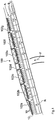
- the Fig. 1 shows a linkage 100 according to the invention of an agricultural spraying device, which applies a spray liquid containing active substances essentially transversely to a direction of travel F, in particular while cornering, on an agricultural area N.
- the linkage 100 comprises a plurality of linkage sections 102a-102g, preferably articulated with one another and / or pivotable, on which a plurality of nozzle holders 10 designed as multiple nozzle bodies are arranged.
- Each nozzle holder 10 has three nozzles 12, by means of which the spray liquid can be applied in the form of spray jets and / or spray fans A.
- the nozzle holders 10, in particular nozzles 12, are in fluid communication by means of a supply line not shown in the illustrations.
- the spray liquid is provided to the nozzle holders 10, in particular nozzles 12, in the form of a spray liquid circuit with an adjustable fluid pressure from a reservoir, also not shown, which is fluidically connected to the supply line.
- the spray device also includes a control and / or regulating device, not shown in the figures and designed as a control unit, which is set up, among other things, to activate and / or control the nozzle holders 10, in particular nozzles 12, for the application of the spray liquid.
- a control and / or regulating device which is set up, among other things, to activate and / or control the nozzle holders 10, in particular nozzles 12, for the application of the spray liquid.
- the nozzles 12 arranged within a nozzle holder 10 can be controlled and / or activated individually and / or in combination.
- the control unit can take into account a speed and / or rotation rate and / or target application rate of at least one nozzle holder 10, in particular a nozzle 12.
- the deviation of the application rate adjustable by the control unit of at least one nozzle holder 10, in particular nozzle 12, is minimal from the target application rate, preferably zero.
- the nozzle holders 10, in particular nozzles 12 are assigned as a function of at least one parameter, preferably variable, partial widths.
- the partial widths can preferably be defined by different speed intervals, in particular speed ranges, of a fixed size.
- a Such a definition of the partial widths is particularly useful for cornering in which the nozzle holders 10, in particular nozzles 12, have different path and / or circumferential speeds along the rod 100, which are particularly dependent on the curve radius.
- nozzle holders 10 are taken into account for determining the partial widths and / or for activating and / or controlling the nozzle holders 10, in particular nozzles 12.
- the spray properties such as the application rate and / or the spray angle, of the nozzle holder 10, in particular the nozzle 12, are of decisive importance.
- the respective spray properties differ at least in part from the nozzles 12 fitted within a nozzle holder 10.
- the fluid pressure of the spray liquid applied to at least one nozzle holder 10, in particular nozzle 12 is used as an alternative or in addition to define the sections and / or for activation and / or control of the nozzle holders 10, in particular nozzles 12, detected and / or taken into account.
- a particularly homogeneous application result of the spray liquid on the agricultural area N and / or its vegetation is achieved in that the spray jets and / or spray fans A, preferably at least two adjacent nozzle holders 10, in particular nozzles 12, as in FIG Fig. 1 shown overlap at least partially.
- the amount applied, in particular on the area overlapped by at least two spray jets and / or spray fans A corresponds to the specified target application rate, in particular the target application rate.
- the application rates of several nozzle holders, in particular nozzles can thus be combined, as a result of which a particularly wide range of application quantities, in particular application quantities C, is achieved by means of the attached nozzle holders 10, in particular nozzles 12.
- the position of the individual nozzle holders 10, in particular nozzles 12, is taken into account for assigning and / or defining the partial widths.
- the position of the spray device and / or at least one nozzle holder 12, in particular nozzle 12 can be determined by means of a sensor can be detected and / or additionally determined with the aid of geometric information from the spray device, which can preferably be stored on the control unit.
- the control unit can thus determine whether at least one nozzle holder 10, in particular nozzle 12, is located on an agricultural area N and the at least one nozzle 12 and / or a group of nozzle holders 10, in particular nozzles 12, can be activated and / or deactivated.
- FIG. 1 of line B An assignment of the nozzle holders 10, in particular nozzles 12, to a, preferably variable, partial width can be carried out in accordance with FIG Fig. 1 of line B.
- Each column of row B represents on the one hand the nozzle size and / or combination B of nozzles 12 located above the column and on the other hand the width of the respective partial width.
- the nozzles 12 with the size 02 are activated in the respective nozzle holders 10, whereby the corresponding application quantity C, 02 of the spray liquid on the agricultural area N is achieved by the overlapping of the spray compartments A.
- the nozzles 12 with the nozzle size 02 and 04 are activated alternately within the second partial width from the left in the nozzle holders.
- the nozzle 12 with the nozzle size 04 is activated on the individual nozzle holders 10.
- an application amount C, 05 is achieved by overlapping the spray fan A.
- nozzle sizes 02 and 04 are activated jointly on all nozzle holders 10 assigned for this purpose, an application quantity C, 06 thus being implemented.
- An application amount C, 07 is achieved by a section with alternating activated nozzle holders 10 with the nozzle sizes 02 with 06 and 02 with 04.
- the nozzle sizes 02 and 06 are activated on the respective assigned nozzle holders 10, so that an application quantity C, 08 can be applied.
- the control unit assigned to the spray device is set up to determine the sections, preferably variably, on the basis of a predetermined target application quantity that can be called up on an application map that can be stored in the control unit.
- the target application quantities are here part-area-specifically assigned to the sub-areas T1-T7 into which the agricultural area N can be subdivided, the sub-areas T1-T7 each having different target application quantities.
Landscapes
- Life Sciences & Earth Sciences (AREA)
- Engineering & Computer Science (AREA)
- Insects & Arthropods (AREA)
- Pest Control & Pesticides (AREA)
- Wood Science & Technology (AREA)
- Zoology (AREA)
- Environmental Sciences (AREA)
- Catching Or Destruction (AREA)
Applications Claiming Priority (1)
| Application Number | Priority Date | Filing Date | Title |
|---|---|---|---|
| DE102019134254.6A DE102019134254A1 (de) | 2019-12-13 | 2019-12-13 | Vorrichtung und Verfahren zur Ausbringung von Spritzflüssigkeit auf einer landwirtschaftlichen Fläche |
Publications (1)
| Publication Number | Publication Date |
|---|---|
| EP3834612A1 true EP3834612A1 (fr) | 2021-06-16 |
Family
ID=74125034
Family Applications (1)
| Application Number | Title | Priority Date | Filing Date |
|---|---|---|---|
| EP20401064.9A Pending EP3834612A1 (fr) | 2019-12-13 | 2020-12-03 | Dispositif et procédé d'application d'un liquide à pulvériser sur une surface agricole |
Country Status (2)
| Country | Link |
|---|---|
| EP (1) | EP3834612A1 (fr) |
| DE (1) | DE102019134254A1 (fr) |
Cited By (1)
| Publication number | Priority date | Publication date | Assignee | Title |
|---|---|---|---|---|
| WO2023170222A1 (fr) * | 2022-03-10 | 2023-09-14 | Basf Agro Trademarks Gmbh | Procédé mis en œuvre par ordinateur pour fournir des données de dose d'application variable |
Citations (4)
| Publication number | Priority date | Publication date | Assignee | Title |
|---|---|---|---|---|
| EP2826366A1 (fr) * | 2013-07-18 | 2015-01-21 | Herbert Dammann GmbH | Procédé de vaporisation de surface de liquide pour dispositifs de distribution de liquide motorisés |
| WO2016030368A1 (fr) * | 2014-08-29 | 2016-03-03 | Horsch Leeb Application Systems Gmbh | Machine agricole d'épandage munie d'un système de commande automatisé de profils de pulvérisation |
| EP2995382A1 (fr) * | 2014-09-15 | 2016-03-16 | Deere & Company | Système de buse de pulvérisation, rampe de pulvérisation avec celui-ci et véhicule agricole ayant une telle rampe de pulvérisation |
| US9339023B2 (en) | 2010-09-10 | 2016-05-17 | Exel Industries | Spraying apparatus for agricultural machine with cartographic piloting |
-
2019
- 2019-12-13 DE DE102019134254.6A patent/DE102019134254A1/de active Pending
-
2020
- 2020-12-03 EP EP20401064.9A patent/EP3834612A1/fr active Pending
Patent Citations (5)
| Publication number | Priority date | Publication date | Assignee | Title |
|---|---|---|---|---|
| US9339023B2 (en) | 2010-09-10 | 2016-05-17 | Exel Industries | Spraying apparatus for agricultural machine with cartographic piloting |
| EP2826366A1 (fr) * | 2013-07-18 | 2015-01-21 | Herbert Dammann GmbH | Procédé de vaporisation de surface de liquide pour dispositifs de distribution de liquide motorisés |
| WO2016030368A1 (fr) * | 2014-08-29 | 2016-03-03 | Horsch Leeb Application Systems Gmbh | Machine agricole d'épandage munie d'un système de commande automatisé de profils de pulvérisation |
| DE102014112441A1 (de) * | 2014-08-29 | 2016-03-03 | Horsch Leeb Application Systems Gmbh | Landwirtschaftliche Verteilmaschine mit einem System zur automatisierten Ansteuerung von Spritzprofilen |
| EP2995382A1 (fr) * | 2014-09-15 | 2016-03-16 | Deere & Company | Système de buse de pulvérisation, rampe de pulvérisation avec celui-ci et véhicule agricole ayant une telle rampe de pulvérisation |
Cited By (1)
| Publication number | Priority date | Publication date | Assignee | Title |
|---|---|---|---|---|
| WO2023170222A1 (fr) * | 2022-03-10 | 2023-09-14 | Basf Agro Trademarks Gmbh | Procédé mis en œuvre par ordinateur pour fournir des données de dose d'application variable |
Also Published As
| Publication number | Publication date |
|---|---|
| DE102019134254A1 (de) | 2021-06-17 |
Similar Documents
| Publication | Publication Date | Title |
|---|---|---|
| EP3185680B1 (fr) | Pulvérisateur agricole comprenant un système pour le control automatique des profiles de pulvérisation | |
| EP3649857B1 (fr) | Appareil de pulvérisation agricole | |
| EP2022329A2 (fr) | Dispositif de pulvérisation mobile doté d'une tige de pulvérisation et procédé de réglage de ses buses de pulvérisation | |
| EP3556208B1 (fr) | Épandeur agricole et procédé d'épandage de substances actives liquides | |
| EP3539376B1 (fr) | Système de distribution d'un pulvérisateur agricole doté d'un agencement optimisé de buses de distribution et procédé d'épandage de fluides de pulvérisation | |
| EP4094577A1 (fr) | Pulvérisateur agricole et dispositif pulvérisateur pour un pulvérisateur agricole, ainsi que procédé d' ajustement d' un dispositif pulvérisateur pour une distribution par rangé e du liquide de pulvérisation | |
| EP3308644B1 (fr) | Système de commande et/ou de réglage d'une machine agricole | |
| WO2020083771A1 (fr) | Dispositif de pulvérisation agricole | |
| EP3834612A1 (fr) | Dispositif et procédé d'application d'un liquide à pulvériser sur une surface agricole | |
| EP3485729B1 (fr) | Procédé de distribution d'un fluide de pulvérisation sur une surface utile agricole | |
| EP3501252B1 (fr) | Système de commande et/ou de réglage, véhicule agricole et procédé de commande et/ou de réglage d'un véhicule agricole | |
| EP3300598A1 (fr) | Procédé et dispositif de pulvérisation permettant la distribution d'un fluide de pulvérisation sur une superficie agricole | |
| DE69808434T2 (de) | Sprühdüse | |
| DE102020109024A1 (de) | Landwirtschaftliche pneumatische Verteilmaschine | |
| WO2024184143A1 (fr) | Dispositif de pulvérisation agricole | |
| EP3485728B1 (fr) | Machine d'épandage agricole | |
| EP4218410B1 (fr) | Procédé de distribution du liquide | |
| WO2023156231A1 (fr) | Procédé de commande en boucle ouverte et/ou en boucle fermée d'une machine de distribution agricole et machine de distribution agricole | |
| EP4298904A1 (fr) | Procédé d'épandage de produit de pulvérisation sur une surface agricole à l'arbre au moyen d'un dispositif de pulvérisation agricole | |
| DE102023105531A1 (de) | Landwirtschaftliche Spritzeinrichtung | |
| EP4230038A1 (fr) | Machine de répartition agricole et procédé de répartition précise en position d'agents actifs agricoles | |
| DE102022130299A1 (de) | Verfahren zum Ausbringen von Spritzmittel auf einer landwirtschaftlichen Nutzfläche und landwirtschaftliche Spritzeinrichtung | |
| DE102020112619A1 (de) | Landwirtschaftliche Feldspritze | |
| WO2025131807A1 (fr) | Système de traitement de données pour un engin agricole et procédé de commande d'un engin agricole | |
| DE102021112691A1 (de) | Landwirtschaftliche feldspritze und spritzvorrichtung für eine landwirtschaftliche feldspritze |
Legal Events
| Date | Code | Title | Description |
|---|---|---|---|
| PUAI | Public reference made under article 153(3) epc to a published international application that has entered the european phase |
Free format text: ORIGINAL CODE: 0009012 |
|
| STAA | Information on the status of an ep patent application or granted ep patent |
Free format text: STATUS: THE APPLICATION HAS BEEN PUBLISHED |
|
| AK | Designated contracting states |
Kind code of ref document: A1 Designated state(s): AL AT BE BG CH CY CZ DE DK EE ES FI FR GB GR HR HU IE IS IT LI LT LU LV MC MK MT NL NO PL PT RO RS SE SI SK SM TR |
|
| STAA | Information on the status of an ep patent application or granted ep patent |
Free format text: STATUS: REQUEST FOR EXAMINATION WAS MADE |
|
| 17P | Request for examination filed |
Effective date: 20211005 |
|
| RBV | Designated contracting states (corrected) |
Designated state(s): AL AT BE BG CH CY CZ DE DK EE ES FI FR GB GR HR HU IE IS IT LI LT LU LV MC MK MT NL NO PL PT RO RS SE SI SK SM TR |
|
| STAA | Information on the status of an ep patent application or granted ep patent |
Free format text: STATUS: EXAMINATION IS IN PROGRESS |
|
| 17Q | First examination report despatched |
Effective date: 20230213 |
|
| P01 | Opt-out of the competence of the unified patent court (upc) registered |
Effective date: 20230523 |