EP3835109A1 - Véhicule électrique, combinaison d'une pluralité de véhicules électriques et procédé de fonctionnement d'un véhicule électrique - Google Patents
Véhicule électrique, combinaison d'une pluralité de véhicules électriques et procédé de fonctionnement d'un véhicule électrique Download PDFInfo
- Publication number
- EP3835109A1 EP3835109A1 EP19214676.9A EP19214676A EP3835109A1 EP 3835109 A1 EP3835109 A1 EP 3835109A1 EP 19214676 A EP19214676 A EP 19214676A EP 3835109 A1 EP3835109 A1 EP 3835109A1
- Authority
- EP
- European Patent Office
- Prior art keywords
- power supply
- intermediate circuit
- direct current
- external power
- electric vehicle
- Prior art date
- Legal status (The legal status is an assumption and is not a legal conclusion. Google has not performed a legal analysis and makes no representation as to the accuracy of the status listed.)
- Pending
Links
- 238000000034 method Methods 0.000 title claims description 15
- 230000002457 bidirectional effect Effects 0.000 claims abstract description 5
- 238000001514 detection method Methods 0.000 claims description 15
- 239000003990 capacitor Substances 0.000 claims description 8
- 239000002131 composite material Substances 0.000 claims description 2
- 238000004146 energy storage Methods 0.000 claims description 2
- 239000004065 semiconductor Substances 0.000 claims description 2
- 238000010586 diagram Methods 0.000 description 3
- 238000005259 measurement Methods 0.000 description 3
- 238000004590 computer program Methods 0.000 description 2
- 230000001172 regenerating effect Effects 0.000 description 2
- 230000000694 effects Effects 0.000 description 1
- 230000005611 electricity Effects 0.000 description 1
- 238000004519 manufacturing process Methods 0.000 description 1
- 239000000463 material Substances 0.000 description 1
- 238000000926 separation method Methods 0.000 description 1
- 230000007704 transition Effects 0.000 description 1
Images

Classifications
-
- B—PERFORMING OPERATIONS; TRANSPORTING
- B60—VEHICLES IN GENERAL
- B60L—PROPULSION OF ELECTRICALLY-PROPELLED VEHICLES; SUPPLYING ELECTRIC POWER FOR AUXILIARY EQUIPMENT OF ELECTRICALLY-PROPELLED VEHICLES; ELECTRODYNAMIC BRAKE SYSTEMS FOR VEHICLES IN GENERAL; MAGNETIC SUSPENSION OR LEVITATION FOR VEHICLES; MONITORING OPERATING VARIABLES OF ELECTRICALLY-PROPELLED VEHICLES; ELECTRIC SAFETY DEVICES FOR ELECTRICALLY-PROPELLED VEHICLES
- B60L5/00—Current collectors for power supply lines of electrically-propelled vehicles
- B60L5/18—Current collectors for power supply lines of electrically-propelled vehicles using bow-type collectors in contact with trolley wire
-
- B—PERFORMING OPERATIONS; TRANSPORTING
- B60—VEHICLES IN GENERAL
- B60L—PROPULSION OF ELECTRICALLY-PROPELLED VEHICLES; SUPPLYING ELECTRIC POWER FOR AUXILIARY EQUIPMENT OF ELECTRICALLY-PROPELLED VEHICLES; ELECTRODYNAMIC BRAKE SYSTEMS FOR VEHICLES IN GENERAL; MAGNETIC SUSPENSION OR LEVITATION FOR VEHICLES; MONITORING OPERATING VARIABLES OF ELECTRICALLY-PROPELLED VEHICLES; ELECTRIC SAFETY DEVICES FOR ELECTRICALLY-PROPELLED VEHICLES
- B60L50/00—Electric propulsion with power supplied within the vehicle
- B60L50/50—Electric propulsion with power supplied within the vehicle using propulsion power supplied by batteries or fuel cells
- B60L50/53—Electric propulsion with power supplied within the vehicle using propulsion power supplied by batteries or fuel cells in combination with an external power supply, e.g. from overhead contact lines
-
- B—PERFORMING OPERATIONS; TRANSPORTING
- B60—VEHICLES IN GENERAL
- B60L—PROPULSION OF ELECTRICALLY-PROPELLED VEHICLES; SUPPLYING ELECTRIC POWER FOR AUXILIARY EQUIPMENT OF ELECTRICALLY-PROPELLED VEHICLES; ELECTRODYNAMIC BRAKE SYSTEMS FOR VEHICLES IN GENERAL; MAGNETIC SUSPENSION OR LEVITATION FOR VEHICLES; MONITORING OPERATING VARIABLES OF ELECTRICALLY-PROPELLED VEHICLES; ELECTRIC SAFETY DEVICES FOR ELECTRICALLY-PROPELLED VEHICLES
- B60L3/00—Electric devices on electrically-propelled vehicles for safety purposes; Monitoring operating variables, e.g. speed, deceleration or energy consumption
- B60L3/12—Recording operating variables ; Monitoring of operating variables
-
- B—PERFORMING OPERATIONS; TRANSPORTING
- B60—VEHICLES IN GENERAL
- B60L—PROPULSION OF ELECTRICALLY-PROPELLED VEHICLES; SUPPLYING ELECTRIC POWER FOR AUXILIARY EQUIPMENT OF ELECTRICALLY-PROPELLED VEHICLES; ELECTRODYNAMIC BRAKE SYSTEMS FOR VEHICLES IN GENERAL; MAGNETIC SUSPENSION OR LEVITATION FOR VEHICLES; MONITORING OPERATING VARIABLES OF ELECTRICALLY-PROPELLED VEHICLES; ELECTRIC SAFETY DEVICES FOR ELECTRICALLY-PROPELLED VEHICLES
- B60L9/00—Electric propulsion with power supply external to the vehicle
-
- H—ELECTRICITY
- H02—GENERATION; CONVERSION OR DISTRIBUTION OF ELECTRIC POWER
- H02P—CONTROL OR REGULATION OF ELECTRIC MOTORS, ELECTRIC GENERATORS OR DYNAMO-ELECTRIC CONVERTERS; CONTROLLING TRANSFORMERS, REACTORS OR CHOKE COILS
- H02P27/00—Arrangements or methods for the control of AC motors characterised by the kind of supply voltage
- H02P27/04—Arrangements or methods for the control of AC motors characterised by the kind of supply voltage using variable-frequency supply voltage, e.g. inverter or converter supply voltage
- H02P27/06—Arrangements or methods for the control of AC motors characterised by the kind of supply voltage using variable-frequency supply voltage, e.g. inverter or converter supply voltage using DC to AC converters or inverters
-
- H—ELECTRICITY
- H02—GENERATION; CONVERSION OR DISTRIBUTION OF ELECTRIC POWER
- H02P—CONTROL OR REGULATION OF ELECTRIC MOTORS, ELECTRIC GENERATORS OR DYNAMO-ELECTRIC CONVERTERS; CONTROLLING TRANSFORMERS, REACTORS OR CHOKE COILS
- H02P5/00—Arrangements specially adapted for regulating or controlling the speed or torque of two or more electric motors
- H02P5/74—Arrangements specially adapted for regulating or controlling the speed or torque of two or more electric motors controlling two or more AC dynamo-electric motors
-
- Y—GENERAL TAGGING OF NEW TECHNOLOGICAL DEVELOPMENTS; GENERAL TAGGING OF CROSS-SECTIONAL TECHNOLOGIES SPANNING OVER SEVERAL SECTIONS OF THE IPC; TECHNICAL SUBJECTS COVERED BY FORMER USPC CROSS-REFERENCE ART COLLECTIONS [XRACs] AND DIGESTS
- Y02—TECHNOLOGIES OR APPLICATIONS FOR MITIGATION OR ADAPTATION AGAINST CLIMATE CHANGE
- Y02T—CLIMATE CHANGE MITIGATION TECHNOLOGIES RELATED TO TRANSPORTATION
- Y02T10/00—Road transport of goods or passengers
- Y02T10/60—Other road transportation technologies with climate change mitigation effect
- Y02T10/70—Energy storage systems for electromobility, e.g. batteries
Definitions
- the invention relates to an electric vehicle, a combination of several electric vehicles and a method for operating an electric vehicle.
- Electrically powered vehicles such as rail vehicles are often powered by an external power supply system such as an overhead line.
- an external power supply system such as an overhead line.
- power supply systems are often divided into independent supply sections. Between these independent supply sections there are electroless sections which the vehicle must traverse. This has the disadvantage that the power supply to the auxiliary systems is interrupted and the comfort for the passengers is reduced. This also results in a load shedding of the traction, which leads to increased stress on the traction components.
- the object of the invention is thus to eliminate these and other disadvantages of the prior art and, in particular, to prevent a currentless section of a power supply system from being energized via a current collector of the vehicle. Furthermore, an energy supply for the vehicle should also be ensured in the currentless sections without placing too much stress on the components of the vehicle. Inrush phenomena such as electric arcs are also to be prevented.
- the object is achieved by an electric vehicle, in particular a rail vehicle, with a power consumption device.
- the power consumption device has at least one contact device.
- An electrically conductive contact between the power receiving device and an external power supply can be achieved by the contact device.
- the rail vehicle further comprises a direct current intermediate circuit and at least one electric traction motor.
- the current from the current receiving device can be conducted into the traction motors via the direct current intermediate circuit, and a current connection is established between the contact device and the direct current intermediate circuit.
- the power connection is at least partially bidirectional.
- a separating device is arranged between the contact device and the direct current intermediate circuit. The separating device is designed in such a way that the power supply can only be interrupted unidirectionally, in particular a current flow in the direction of the external power supply, preferably in the direction of the contact device, can be interrupted.
- the power supply which can only be interrupted unidirectionally, means that the vehicle can draw power from the external power supply at any time, but optionally no power can flow out of the vehicle. For example, it can be prevented in this way that current can flow from the direct current intermediate circuit into a currentless section of the power supply. It can thus be prevented that the currentless section is inadvertently energized.
- the isolating device is closed and current can be fed into the external power supply, for example during regenerative braking.
- a disconnection device is understood here as a device which enables at least a partial interruption of the current connection, for example by reducing the current flow.
- the separating device is preferably designed in such a way that the power connection can be completely disconnected, that is to say no more current can flow from the vehicle into the currentless section.
- An electric vehicle is understood here to mean that it is an electrically moving unit.
- the current pickup device can comprise a current collector such as a bar current collector, for example with a sliding shoe or with a contact roller, a current collector bracket for connection to a busbar or an overhead line or other suitable pick-up devices.
- a current collector such as a bar current collector, for example with a sliding shoe or with a contact roller, a current collector bracket for connection to a busbar or an overhead line or other suitable pick-up devices.
- the vehicle can include further electrical components, such as further switches or rectifiers.
- the isolating device is preferably an electronic switch, preferably a semiconductor switch with a free-wheeling diode, particularly preferably an IGBT with a free-wheeling diode.
- This structure is easy to manufacture and not very complex.
- the disconnection device can comprise other, suitable disconnection devices which, in the open state, interrupt the flow of current from the vehicle into the external power supply.
- the flow of current in the opposite direction should still be possible.
- the vehicle can include a reducing device which, for example, only allows a small flow of current into the external power supply during the currentless section. In this way, the current flow into the currentless section can be reduced in a simple manner.
- a power storage device is preferably provided, in particular a battery or a capacitor, in particular a super capacitor.
- the power storage device is arranged in electrical connection with the direct current intermediate circuit.
- the power storage device is preferably connected to the direct current intermediate circuit via a step-up converter.
- the capacitance of the capacitor can preferably be designed for the required power of the vehicle and auxiliary operating power and the length of the currentless sections.
- the capacity of the capacitor can be at least 1 kWh.
- a main switch is preferably arranged between the contact device and the direct current intermediate circuit, preferably between the contact device and separating device, particularly preferably between the power receiving device and the separating device.
- connection or connected is used here if there is a current-conducting line between the components.
- the vehicle can include further switches.
- the current consumption device preferably comprises a measuring device for current.
- the vehicle preferably comprises a data processing device for controlling the separating device.
- the separating device can be actuatable, in particular switchable, by a user and / or automatically actuatable, in particular switchable, by the data processing device, preferably by recognizing a measured value of the measuring device.
- the measuring device is preferably connected to all contact devices so that current can be measured through all contact devices.
- the measuring device comprises at least one measuring element for each contact device, which is spaced apart from the other contact devices in the longitudinal direction of the vehicle, so that an individual measurement of the current through each contact device is possible. If the current is taken from the side of busbars, there are usually two contact devices on the right and left of the vehicle Essentially the same point lengthways. These two contact devices can be connected to a common measuring element. In this way, individual measurements for each contact device can be carried out easily and without unnecessary material expenditure.
- the power consumption device can thus comprise, for example, two contact devices through which current can flow at the same time.
- the power supply is only interrupted if the length of the section of the external power supply without a power supply is longer than the distance between the two power receiving devices.
- a detection device is preferably designed for detecting power supply interruptions. The presence of a power supply interruption can be directly detected by the detection device and / or position data of a power supply interruption can be processed in the detection device.
- the detection device can comprise at least one data receiving device and / or data sending device which is designed to send or receive data to other vehicles or from an external data processing device or network, preferably position data from currentless sections.
- the detection device can preferably be connected and / or connectable to the vehicle-internal data processing device, so that the disconnection device can be switched in accordance with the received data.
- the object is also achieved by a combination of several electric vehicles, in particular rail vehicles. At least one electric vehicle as previously described is provided.
- the vehicle or vehicles driving ahead can forward the position data to vehicles driving behind or to an external point. This allows a simple compilation of a position plan of currentless sections.
- a voltage level of the direct current intermediate circuit is preferably raised to an equal or higher voltage level than the voltage level of the external power supply, in particular to a maximum permissible voltage of the external power supply.
- a resumption of the external power supply is preferably detected by the detection device.
- the voltage level in the direct current intermediate circuit is reduced after the reconnection of the external power supply has been detected, preferably to a level below the voltage level of the external power supply and the supply of the intermediate circuit by the battery or recuperation is interrupted.
- the separating device is closed again so that a bidirectional current flow is possible.
- the detection device measures the external voltage and in particular the harmonic components. This is advantageous because at this point in time no current is flowing into the vehicle due to the higher voltage.
- the voltage level in the direct current intermediate circuit is preferably increased by feeding in braking energy from the traction motors and / or by feeding in energy from an energy store.
- the current interruption is preferably detected in an electric vehicle with more than one current collection device instead of the current collection device arranged foremost in the direction of travel.
- a length of the section of the current interruption of the external power supply is preferably determined.
- a composite preferably comprises at least two power receiving devices which are spaced apart in the longitudinal direction.
- the power supply is only interrupted if the length of the section of the external power supply without a power supply is longer than the distance between the two power receiving devices.
- the length of the section of the power interruption of the external power supply is preferably sent to another vehicle and / or stored.
- a position plan of currentless sections can easily be created, which enables the circuit of the isolating device to be optimized. For example, if a first Vehicle drives through a currentless section and this can be bridged, that is, is always connected at least at one point to a current-carrying section of the external power supply, the second vehicle following behind can avoid switching the isolating device.
- the object is also achieved by a computer program product.
- the computer program product comprises the commands which, when the program is executed by a data processing device, a method as described above carries out.
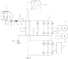
- FIG. 13 shows a diagram of an electric power supply of a vehicle in a first embodiment.
- a power consumption device 2 can be seen with two contact devices 2a, 2b, which bring the vehicle into electrically conductive contact with an external power supply 1.
- the contact devices 2a, 2b are each connected to a current transformer 13a, 13b for current measurement.
- connection or connected is designed here in such a way that a current-conducting line is arranged between components.
- the two current transformers 13a, 13b are connected to a main switch 3.
- An additional voltage converter 20 is arranged on the line from the current converter 13a to the main switch 4.
- the main switch 3 is connected to an inductance 14, which in turn is connected to a line contactor 4 and a charging contactor 15 connected in parallel thereto.
- the line contactor 4 and the charging contactor 15 are connected to the separating device 5.
- the separating device 5 comprises two free-wheeling diodes 12 connected in parallel.
- the two current transformers 13a, 13b can be connected to the inductance 14 directly or via a fuse.
- the separating device 5 is connected to the direct current intermediate circuit 11.
- the direct current intermediate circuit 11 comprises a capacitor 16.
- An energy storage device, here capacitance 6, is connected in parallel to the direct current intermediate circuit 11 and connected to it via a step-up converter 21.
- the capacitance 6 can take over the power supply of the direct current intermediate circuit 11 or be charged via this.
- the traction motors 10 are connected to the direct current intermediate circuit 11 via a motor converter 7.
- the auxiliaries 9 are also connected to the DC link 11 via auxiliary converters 8.
- the separating device 5 is closed again, and current can now flow bidirectionally again.
- the capacitance 6 is recharged via the direct current intermediate circuit.
- An earth brush 17 for the return current is also shown.
- FIG. 13 shows a diagram of an electric power supply of a vehicle in a second embodiment. Only the differences from the first embodiment are explained here.
- the isolating device 5 in this embodiment is arranged between the current transformers 13a, 13b and the main switch 3.
- the isolating device here comprises a freewheeling diode 18 which is connected in parallel with an IGBT switch.
Landscapes
- Engineering & Computer Science (AREA)
- Power Engineering (AREA)
- Transportation (AREA)
- Mechanical Engineering (AREA)
- Life Sciences & Earth Sciences (AREA)
- Sustainable Development (AREA)
- Sustainable Energy (AREA)
- Electric Propulsion And Braking For Vehicles (AREA)
Priority Applications (2)
| Application Number | Priority Date | Filing Date | Title |
|---|---|---|---|
| EP19214676.9A EP3835109A1 (fr) | 2019-12-10 | 2019-12-10 | Véhicule électrique, combinaison d'une pluralité de véhicules électriques et procédé de fonctionnement d'un véhicule électrique |
| US16/953,514 US11541759B2 (en) | 2019-12-10 | 2020-11-20 | Electric vehicle, composition of several electric vehicles and method for operating an electric vehicle |
Applications Claiming Priority (1)
| Application Number | Priority Date | Filing Date | Title |
|---|---|---|---|
| EP19214676.9A EP3835109A1 (fr) | 2019-12-10 | 2019-12-10 | Véhicule électrique, combinaison d'une pluralité de véhicules électriques et procédé de fonctionnement d'un véhicule électrique |
Publications (1)
| Publication Number | Publication Date |
|---|---|
| EP3835109A1 true EP3835109A1 (fr) | 2021-06-16 |
Family
ID=68847959
Family Applications (1)
| Application Number | Title | Priority Date | Filing Date |
|---|---|---|---|
| EP19214676.9A Pending EP3835109A1 (fr) | 2019-12-10 | 2019-12-10 | Véhicule électrique, combinaison d'une pluralité de véhicules électriques et procédé de fonctionnement d'un véhicule électrique |
Country Status (2)
| Country | Link |
|---|---|
| US (1) | US11541759B2 (fr) |
| EP (1) | EP3835109A1 (fr) |
Citations (6)
| Publication number | Priority date | Publication date | Assignee | Title |
|---|---|---|---|---|
| JPS592501A (ja) * | 1982-06-28 | 1984-01-09 | Fuji Electric Co Ltd | 交流電気車のデツドセクシヨン検出方法 |
| US5331261A (en) * | 1990-12-20 | 1994-07-19 | General Electric Company | Regenerative braking protection for an electrically-propelled traction vehicle |
| EP0691236A1 (fr) | 1994-07-06 | 1996-01-10 | ABBPATENT GmbH | Procédé pour franchir des tronçons hors tension dans l'alimentation de véhicules ferroviaires électriques |
| EP2011685A1 (fr) | 2006-04-25 | 2009-01-07 | Mitsubishi Denki Kabushiki Kaisha | Dispositif de commande pour vehicule electrique |
| EP2810847A1 (fr) * | 2012-02-03 | 2014-12-10 | Mitsubishi Electric Corporation | Dispositif de commande de coupe-circuit pour train électrique |
| DE102015215178A1 (de) * | 2015-08-07 | 2017-02-09 | Siemens Aktiengesellschaft | Vorrichtung und ein Verfahren zum oberleitungslosen Betreiben eines Schienenfahrzeugs |
Family Cites Families (2)
| Publication number | Priority date | Publication date | Assignee | Title |
|---|---|---|---|---|
| CZ20131030A3 (cs) * | 2013-12-19 | 2015-07-01 | Inekon Group, A.S. | Pohon trakčního vozidla |
| EP3109090A4 (fr) * | 2014-02-20 | 2018-03-07 | Coordenação Dos Programas De Pós Graduação De Engenharia Da Universidade Federal Do Rio De Janeiro | Systèmes intelligents de gestion d'énergie pour véhicules électriques et électriques-hybrides avec connexion bidirectionnelle, système intelligent de gestion d'énergie pour générateur d'énergie, procédé de gestion d'énergie dans un système intelligent de gestion d'énergie, et procédé pour commander le fonctionnement d'un générateur d'énergie |
-
2019
- 2019-12-10 EP EP19214676.9A patent/EP3835109A1/fr active Pending
-
2020
- 2020-11-20 US US16/953,514 patent/US11541759B2/en active Active
Patent Citations (6)
| Publication number | Priority date | Publication date | Assignee | Title |
|---|---|---|---|---|
| JPS592501A (ja) * | 1982-06-28 | 1984-01-09 | Fuji Electric Co Ltd | 交流電気車のデツドセクシヨン検出方法 |
| US5331261A (en) * | 1990-12-20 | 1994-07-19 | General Electric Company | Regenerative braking protection for an electrically-propelled traction vehicle |
| EP0691236A1 (fr) | 1994-07-06 | 1996-01-10 | ABBPATENT GmbH | Procédé pour franchir des tronçons hors tension dans l'alimentation de véhicules ferroviaires électriques |
| EP2011685A1 (fr) | 2006-04-25 | 2009-01-07 | Mitsubishi Denki Kabushiki Kaisha | Dispositif de commande pour vehicule electrique |
| EP2810847A1 (fr) * | 2012-02-03 | 2014-12-10 | Mitsubishi Electric Corporation | Dispositif de commande de coupe-circuit pour train électrique |
| DE102015215178A1 (de) * | 2015-08-07 | 2017-02-09 | Siemens Aktiengesellschaft | Vorrichtung und ein Verfahren zum oberleitungslosen Betreiben eines Schienenfahrzeugs |
Also Published As
| Publication number | Publication date |
|---|---|
| US20210170875A1 (en) | 2021-06-10 |
| US11541759B2 (en) | 2023-01-03 |
Similar Documents
| Publication | Publication Date | Title |
|---|---|---|
| EP2252477B1 (fr) | Procede et dispositif de controle de liaisons haute tension d'un vehicule hybride | |
| EP2576277B1 (fr) | Circuit électrique pour un accumulateur d'énergie d'un véhicule, station de chargement et procédé de chargement d'un accumulateur d'énergie | |
| DE112017000286T5 (de) | Leistungsumrichtvorrichtung | |
| EP1386389A1 (fr) | Dispositif pour alimenter en energie le reseau de bord multitension d'un vehicule | |
| DE102012008687B4 (de) | Kraftwagen mit einem Hochvolt-Energieversorgungssystem | |
| DE102018205837B3 (de) | Verfahren zum Betreiben eines Fahrzeugs sowie Fahrzeug | |
| DE102022002607B3 (de) | Fahrzeug mit einer elektrischen Schaltungsanordnung und zwei elektrischen Antriebseinheiten und Verfahren zu dessen Betrieb | |
| DE102010051323B4 (de) | Ladesystem zum Laden einer Batterie eines Fahrzeuges mit einem Zwei-Weg-Laderegler | |
| WO2013159821A1 (fr) | Chargeur | |
| EP3023291A1 (fr) | Système de convertisseur destiné à l'entraînement électrique d'un véhicule ferroviaire | |
| DE102020007350A1 (de) | Verfahren zum Betreiben eines elektrischen Fahrzeuges und elektrisches Fahrzeug | |
| DE102022113800B4 (de) | Verfahren zum Betrieb einer elektrischen Maschine, insbesondere in einem Kraftfahrzeug, und Kraftfahrzeug | |
| DE102011076599A1 (de) | Elektrisches Ladesystem | |
| DE102020007348A1 (de) | Verfahren zum Betreiben eines elektrischen Fahrzeuges und elektrisches Fahrzeug | |
| DE102015101283A1 (de) | Verfahren und Vorrichtung zum elektrischen Laden einer Hochvoltbatterie an einem Wechselstromnetz | |
| EP3771589A1 (fr) | Circuit électronique pour un véhicule à trolley, véhicule à trolley et procédé de fonctionnement d'un véhicule à trolley | |
| EP3541652B1 (fr) | Réseau électrique pour un véhicule ferroviaire, véhicule ferroviaire et procédé d'exploitation d'un réseau électrique | |
| DE102019207385B3 (de) | Schaltungsanordnung zur Stromversorgung von straßengebundenen Fahrzeugen und Fahrzeug | |
| DE102024110210B4 (de) | Verfahren zum Betreiben einer elektrischen Leistungsversorgungsvorrichtung, Abschaltsteuervorrichtung und Leistungsversorgungsvorrichtung | |
| EP3835109A1 (fr) | Véhicule électrique, combinaison d'une pluralité de véhicules électriques et procédé de fonctionnement d'un véhicule électrique | |
| EP3925835B1 (fr) | Réseau embarqué pour un véhicule | |
| DE102017201350B4 (de) | Verfahren zum Übertragen elektrischer Energie zwischen einem fahrzeugseitigen Energiespeicher und einer Anschlussstation sowie Fahrzeugbordnetz | |
| DE102014018762A1 (de) | Paralleles schaltbares Verbinden von wenigstens zwei elektrischen Energiespeichern mit einer elektrischen Anlage | |
| EP4558348A1 (fr) | Véhicule doté d'un système électrique embarqué | |
| DE112018008148T5 (de) | Leistungsumwandlungsvorrichtung und trennerfassungsverfahren |
Legal Events
| Date | Code | Title | Description |
|---|---|---|---|
| PUAI | Public reference made under article 153(3) epc to a published international application that has entered the european phase |
Free format text: ORIGINAL CODE: 0009012 |
|
| STAA | Information on the status of an ep patent application or granted ep patent |
Free format text: STATUS: THE APPLICATION HAS BEEN PUBLISHED |
|
| AK | Designated contracting states |
Kind code of ref document: A1 Designated state(s): AL AT BE BG CH CY CZ DE DK EE ES FI FR GB GR HR HU IE IS IT LI LT LU LV MC MK MT NL NO PL PT RO RS SE SI SK SM TR |
|
| STAA | Information on the status of an ep patent application or granted ep patent |
Free format text: STATUS: REQUEST FOR EXAMINATION WAS MADE |
|
| 17P | Request for examination filed |
Effective date: 20211028 |
|
| RBV | Designated contracting states (corrected) |
Designated state(s): AL AT BE BG CH CY CZ DE DK EE ES FI FR GB GR HR HU IE IS IT LI LT LU LV MC MK MT NL NO PL PT RO RS SE SI SK SM TR |
|
| STAA | Information on the status of an ep patent application or granted ep patent |
Free format text: STATUS: EXAMINATION IS IN PROGRESS |
|
| 17Q | First examination report despatched |
Effective date: 20230314 |