EP3835113A1 - Ensemble de connexion pour fournir de l'énergie électrique d'une station de charge au sol à un véhicule - Google Patents
Ensemble de connexion pour fournir de l'énergie électrique d'une station de charge au sol à un véhicule Download PDFInfo
- Publication number
- EP3835113A1 EP3835113A1 EP19315159.4A EP19315159A EP3835113A1 EP 3835113 A1 EP3835113 A1 EP 3835113A1 EP 19315159 A EP19315159 A EP 19315159A EP 3835113 A1 EP3835113 A1 EP 3835113A1
- Authority
- EP
- European Patent Office
- Prior art keywords
- connecting assembly
- plug
- electric vehicle
- head
- electric
- Prior art date
- Legal status (The legal status is an assumption and is not a legal conclusion. Google has not performed a legal analysis and makes no representation as to the accuracy of the status listed.)
- Granted
Links
Images


Classifications
-
- B—PERFORMING OPERATIONS; TRANSPORTING
- B60—VEHICLES IN GENERAL
- B60L—PROPULSION OF ELECTRICALLY-PROPELLED VEHICLES; SUPPLYING ELECTRIC POWER FOR AUXILIARY EQUIPMENT OF ELECTRICALLY-PROPELLED VEHICLES; ELECTRODYNAMIC BRAKE SYSTEMS FOR VEHICLES IN GENERAL; MAGNETIC SUSPENSION OR LEVITATION FOR VEHICLES; MONITORING OPERATING VARIABLES OF ELECTRICALLY-PROPELLED VEHICLES; ELECTRIC SAFETY DEVICES FOR ELECTRICALLY-PROPELLED VEHICLES
- B60L53/00—Methods of charging batteries, specially adapted for electric vehicles; Charging stations or on-board charging equipment therefor; Exchange of energy storage elements in electric vehicles
- B60L53/10—Methods of charging batteries, specially adapted for electric vehicles; Charging stations or on-board charging equipment therefor; Exchange of energy storage elements in electric vehicles characterised by the energy transfer between the charging station and the vehicle
- B60L53/14—Conductive energy transfer
-
- B—PERFORMING OPERATIONS; TRANSPORTING
- B60—VEHICLES IN GENERAL
- B60L—PROPULSION OF ELECTRICALLY-PROPELLED VEHICLES; SUPPLYING ELECTRIC POWER FOR AUXILIARY EQUIPMENT OF ELECTRICALLY-PROPELLED VEHICLES; ELECTRODYNAMIC BRAKE SYSTEMS FOR VEHICLES IN GENERAL; MAGNETIC SUSPENSION OR LEVITATION FOR VEHICLES; MONITORING OPERATING VARIABLES OF ELECTRICALLY-PROPELLED VEHICLES; ELECTRIC SAFETY DEVICES FOR ELECTRICALLY-PROPELLED VEHICLES
- B60L53/00—Methods of charging batteries, specially adapted for electric vehicles; Charging stations or on-board charging equipment therefor; Exchange of energy storage elements in electric vehicles
- B60L53/30—Constructional details of charging stations
- B60L53/34—Plug-like or socket-like devices specially adapted for contactless inductive charging of electric vehicles
-
- B—PERFORMING OPERATIONS; TRANSPORTING
- B60—VEHICLES IN GENERAL
- B60L—PROPULSION OF ELECTRICALLY-PROPELLED VEHICLES; SUPPLYING ELECTRIC POWER FOR AUXILIARY EQUIPMENT OF ELECTRICALLY-PROPELLED VEHICLES; ELECTRODYNAMIC BRAKE SYSTEMS FOR VEHICLES IN GENERAL; MAGNETIC SUSPENSION OR LEVITATION FOR VEHICLES; MONITORING OPERATING VARIABLES OF ELECTRICALLY-PROPELLED VEHICLES; ELECTRIC SAFETY DEVICES FOR ELECTRICALLY-PROPELLED VEHICLES
- B60L53/00—Methods of charging batteries, specially adapted for electric vehicles; Charging stations or on-board charging equipment therefor; Exchange of energy storage elements in electric vehicles
- B60L53/30—Constructional details of charging stations
- B60L53/35—Means for automatic or assisted adjustment of the relative position of charging devices and vehicles
-
- H—ELECTRICITY
- H01—ELECTRIC ELEMENTS
- H01R—ELECTRICALLY-CONDUCTIVE CONNECTIONS; STRUCTURAL ASSOCIATIONS OF A PLURALITY OF MUTUALLY-INSULATED ELECTRICAL CONNECTING ELEMENTS; COUPLING DEVICES; CURRENT COLLECTORS
- H01R13/00—Details of coupling devices of the kinds covered by groups H01R12/70 or H01R24/00 - H01R33/00
- H01R13/46—Bases; Cases
- H01R13/52—Dustproof, splashproof, drip-proof, waterproof, or flameproof cases
- H01R13/5202—Sealing means between parts of housing or between housing part and a wall, e.g. sealing rings
-
- H—ELECTRICITY
- H01—ELECTRIC ELEMENTS
- H01R—ELECTRICALLY-CONDUCTIVE CONNECTIONS; STRUCTURAL ASSOCIATIONS OF A PLURALITY OF MUTUALLY-INSULATED ELECTRICAL CONNECTING ELEMENTS; COUPLING DEVICES; CURRENT COLLECTORS
- H01R13/00—Details of coupling devices of the kinds covered by groups H01R12/70 or H01R24/00 - H01R33/00
- H01R13/62—Means for facilitating engagement or disengagement of coupling parts or for holding them in engagement
- H01R13/629—Additional means for facilitating engagement or disengagement of coupling parts, e.g. aligning or guiding means, levers, gas pressure electrical locking indicators, manufacturing tolerances
-
- B—PERFORMING OPERATIONS; TRANSPORTING
- B60—VEHICLES IN GENERAL
- B60L—PROPULSION OF ELECTRICALLY-PROPELLED VEHICLES; SUPPLYING ELECTRIC POWER FOR AUXILIARY EQUIPMENT OF ELECTRICALLY-PROPELLED VEHICLES; ELECTRODYNAMIC BRAKE SYSTEMS FOR VEHICLES IN GENERAL; MAGNETIC SUSPENSION OR LEVITATION FOR VEHICLES; MONITORING OPERATING VARIABLES OF ELECTRICALLY-PROPELLED VEHICLES; ELECTRIC SAFETY DEVICES FOR ELECTRICALLY-PROPELLED VEHICLES
- B60L53/00—Methods of charging batteries, specially adapted for electric vehicles; Charging stations or on-board charging equipment therefor; Exchange of energy storage elements in electric vehicles
- B60L53/30—Constructional details of charging stations
- B60L53/302—Cooling of charging equipment
-
- Y—GENERAL TAGGING OF NEW TECHNOLOGICAL DEVELOPMENTS; GENERAL TAGGING OF CROSS-SECTIONAL TECHNOLOGIES SPANNING OVER SEVERAL SECTIONS OF THE IPC; TECHNICAL SUBJECTS COVERED BY FORMER USPC CROSS-REFERENCE ART COLLECTIONS [XRACs] AND DIGESTS
- Y02—TECHNOLOGIES OR APPLICATIONS FOR MITIGATION OR ADAPTATION AGAINST CLIMATE CHANGE
- Y02T—CLIMATE CHANGE MITIGATION TECHNOLOGIES RELATED TO TRANSPORTATION
- Y02T10/00—Road transport of goods or passengers
- Y02T10/60—Other road transportation technologies with climate change mitigation effect
- Y02T10/70—Energy storage systems for electromobility, e.g. batteries
-
- Y—GENERAL TAGGING OF NEW TECHNOLOGICAL DEVELOPMENTS; GENERAL TAGGING OF CROSS-SECTIONAL TECHNOLOGIES SPANNING OVER SEVERAL SECTIONS OF THE IPC; TECHNICAL SUBJECTS COVERED BY FORMER USPC CROSS-REFERENCE ART COLLECTIONS [XRACs] AND DIGESTS
- Y02—TECHNOLOGIES OR APPLICATIONS FOR MITIGATION OR ADAPTATION AGAINST CLIMATE CHANGE
- Y02T—CLIMATE CHANGE MITIGATION TECHNOLOGIES RELATED TO TRANSPORTATION
- Y02T10/00—Road transport of goods or passengers
- Y02T10/60—Other road transportation technologies with climate change mitigation effect
- Y02T10/7072—Electromobility specific charging systems or methods for batteries, ultracapacitors, supercapacitors or double-layer capacitors
-
- Y—GENERAL TAGGING OF NEW TECHNOLOGICAL DEVELOPMENTS; GENERAL TAGGING OF CROSS-SECTIONAL TECHNOLOGIES SPANNING OVER SEVERAL SECTIONS OF THE IPC; TECHNICAL SUBJECTS COVERED BY FORMER USPC CROSS-REFERENCE ART COLLECTIONS [XRACs] AND DIGESTS
- Y02—TECHNOLOGIES OR APPLICATIONS FOR MITIGATION OR ADAPTATION AGAINST CLIMATE CHANGE
- Y02T—CLIMATE CHANGE MITIGATION TECHNOLOGIES RELATED TO TRANSPORTATION
- Y02T90/00—Enabling technologies or technologies with a potential or indirect contribution to GHG emissions mitigation
- Y02T90/10—Technologies relating to charging of electric vehicles
- Y02T90/12—Electric charging stations
-
- Y—GENERAL TAGGING OF NEW TECHNOLOGICAL DEVELOPMENTS; GENERAL TAGGING OF CROSS-SECTIONAL TECHNOLOGIES SPANNING OVER SEVERAL SECTIONS OF THE IPC; TECHNICAL SUBJECTS COVERED BY FORMER USPC CROSS-REFERENCE ART COLLECTIONS [XRACs] AND DIGESTS
- Y02—TECHNOLOGIES OR APPLICATIONS FOR MITIGATION OR ADAPTATION AGAINST CLIMATE CHANGE
- Y02T—CLIMATE CHANGE MITIGATION TECHNOLOGIES RELATED TO TRANSPORTATION
- Y02T90/00—Enabling technologies or technologies with a potential or indirect contribution to GHG emissions mitigation
- Y02T90/10—Technologies relating to charging of electric vehicles
- Y02T90/14—Plug-in electric vehicles
Definitions
- the invention relates to the field of electric vehicles. More particularly, the invention relates to a connecting assembly for supplying electric energy from a ground charging station to an electric vehicle.
- Protruding guiding systems and/or electrical or mechanical connecting devices tend to occupy valuable space, be dangerously exposed to damages or undesired materials which may aggregate on or beneath them and being carried to them. Any protruding plain surface or volume may also constitute an obstacle to the air-flow during driving and therefore badly alter the aerodynamic behavior and/or create undesired supplementary aerodynamic noise.
- This invention has as its object to remedy to these drawbacks by proposing a new connecting assembly that is configured to be easily connected and disconnected while being protected from the outdoor conditions and by offering a method for securely and reliably implementing said connecting assembly, while protecting sensitive plugging elements plug from outdoor conditions or dirt elements.
- the present invention relates to a connecting assembly for supplying electric energy from a ground charging station to an electric vehicle, characterized in that the connecting assembly comprises at least:
- the figure 1 schematically represents an electric vehicle 2, for example a car or van as suggested.
- a first connector interface 3 which is here located at the bottom of said electric vehicle or car 2.
- the quoted first connecting interface 3 comprises essentially a first electric plug 4 which is here integrated in the bottom of the car itself, as illustrated on figure 1 .
- the first electric plug 4 is hidden.
- an access is given to said first electric plug 4 at all its relevant connecting devices, especially by giving access to the recess containing said first plug 4 or, better, by opening the lodging in which this part is stored when not needed, for example when the car is driving.
- a connecting assembly 1 for supplying electric energy from a ground charging station 8 (as seen on figures 3a-3c and 4a-4c ) to an electric vehicle 2, characterized in that the connecting assembly 1 comprises at least:
- the sliding surface S leads to the first plug 4 when a charging operation is carried out as it will be explained afterwards.
- the connecting assembly 1 is also characterized in the fact that the bottom face of said electric vehicle 2 comprises at least one first electric plug 4 and a plurality of elements 15 located on the bottom of the electric vehicle 2, these elements realizing guiding surfaces 6 and/or contact surfaces 5.
- electric plug one means any electrical device or assembly of compounds that are suitable to establish an electrical temporary connection which can be interrupted manually or automatically.
- the device is "plugged” or “unplugged” as described hereafter or in any usual way well known to the person skilled in the art.
- the "charging" of the battery or any other similar device of the electric vehicle 2 can occur when the first plug 4 and second plug 13 are connected together.
- the guiding surfaces 6 and/or contact surfaces 5 are made by parts of wall portions 15 projecting from the bottom of the electric vehicle 2 towards the ground in a perpendicular or quasi perpendicular direction.
- the surfaces of the wall portions 15 substantially parallel to the bottom surface of the vehicle correspond to the contact surfaces 5 while the surfaces of the wall portions 15 substantially perpendicular to the bottom surface of the vehicle correspond to the guiding surfaces 6.
- the wall portions 15 of the contact surfaces 5 are advantageously tapering towards a rim or edge.
- At least some of the guiding surfaces 6 and/or contact surfaces 5 are arranged on the bottom of the electric vehicle 2 in the shape of a funnel, the narrower open end of which leads to the first electric plug 4. In this way, these elements provide a kind of channel or channels which direct or lead the head 12 of the second electric plug 13 to be connected to the first electric plug 4.
- the guiding surfaces 6 and/or contact surfaces 5 are designed to be retractable in the bottom of the electric vehicle 2.
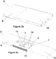
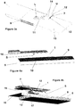
- the connecting assembly 1 is further characterized by the fact that the charging ground station 8 comprises an actuating device to move the connecting head 12 from a "storage" position inside a lodging L of a housing 9 of the ground charging station 8 and protected by a protective cover 10 to an extracted position where said cover 10 is retracted and said head 12 is positioned outside the lodging L and further to an "operating" position where the cover 10 is at least partly positioned over the lodging L of the head 12 in his "storage" position.
- the ground charging station 8 comprises an articulated, slidable arm 11 with the head 12 at its free end, said head 12 being pivotable, i. e. it presents adapted means to be able to carry out such a movement.
- the ground charging station 8 comprises an articulated, slidable arm 11 with the head 12 at its free end, said head 12 being pivotable, i. e. it presents adapted means to be able to carry out such a movement.
- the connecting assembly 1 is also characterized in that said slidable arm 11 has a pivotable flat head 12 bearing a second electric plug 13, said retractable arm 11 presenting means for being slid, elevated, pivoted and pressed against said contact surfaces 5 until the first electric plug 4 of the electric vehicle 2 contacts electrically the second electric plug 13 of the ground charging station 8.
- the contact surfaces 5 formed by the lower surfaces of the wall portions 15 positioned at the bottom of the vehicle 2 realize a discontinue surface making the sliding surface S of the connecting assembly 1, this sliding surface S being arranged to cooperate with the upper surface U of the head 12.
- a special device as a spring, can be easily provided in order to ensure that said head 12 is continuously and sufficiently applied or pressed against said contact surfaces 5 during its corresponding phase of operation.
- a sort of damper or similar can be foreseen that absorbs any excess of pressure possibly applied by the arm 11 when pressing said head 12 against said contact surfaces 5.
- the connecting assembly 1 is also characterized in that the head 12 has a planar or quasi-planar top panel designed to press on said contact surface 5 and provided with at least one guiding pin 14 designed to cooperate with the guiding surfaces 6 when the second electric plug 13 is driven towards or away from the first electric plug 4.
- at least two guiding pins 14 can be provided as shown on the embodiment illustrated by the figures. According to this cooperation, the guiding pin 14 of the head 12 of the second connector interface 7 is driven by sliding along the guiding surfaces 6 formed by the lateral faces of the wall portions 15 while the upper surface U of the head 12 is pressed and slides on the sliding surface S made by the contact surfaces 5 of the wall portions 15.
- the guiding surfaces 6 and the guiding pins 14 differ in their respective heights. Indeed, to cooperate properly, the upper portion of the guiding pins 14 does not interact with the bottom of the vehicle between the wall portions 15. Such arrangement ensures that the upper face U of the head 12 is maintained pressed against the sliding surface S of the connecting assembly 1 without tilting. For this reason, the guiding pins 14 of the head 12 are advantageously smaller in height than the guiding surfaces 6.
- the guiding surfaces 6 or wall portions 15 of the contact surfaces 5 measure 12 mm whereas the pins 14 only measure 10 mm.
- the connecting assembly 1 is also characterized by the fact that the height of each guiding pin 14 is lesser than the height of the wall portions 15.
- the wall portions 15 with the guiding surfaces 6 and/or contact surfaces 5 are separated each other by relatively small gaps or interruptions as shown on the left side of the illustration of figure 2 .
- Such arrangement ensures that the upper surface U of is maintained against at least a portion of the sliding surface S of the connecting assembly 1 without tilting. For this reason, additional contact surfaces 5bis formed by wall portions 15 without specific guiding role are added to increase the stability of the head 12 sliding on the surface S.
- these additional contact surfaces 5bis are arranged to provide a contact of the sliding surface S against the upper surface U of the head 12 on both side of the guiding pins 14 and thus avoid the tilting of the upper surface U of the head 12 with respect to the sliding surface S due to the discontinuity of this sliding surface S and the gap between the contact surfaces 5 for the sliding of the guiding pins 14 of the head 12.
- Such additional contact surfaces 5bis are shown on the right side of figure 2 by two additional parallel portions of contact surfaces 5 which are located outside the funnel designed by the other guiding surfaces 6.
- the connecting elements of the second electrical plug 13 of the head 12 are covered by the closed position of a movable protective lid 18 when the second plug 13 is not electrically connected to the first electric plug 4 of the electric vehicle 2 and uncovered by the opened position of said lid when said second plug 13 is connected or being connected to said first plug 4.
- said lid extends in front of the flat head 12 in direction of the first plug 4 and has the shape of an inclined wall or scraper designed to remove any undesired material that has accumulated at the bottom of the electric vehicle 2 when the second plug 13 is being connected to the first plug 4.
- the movement of the lid and the head 12 can be synchronized so that the lid only opens when the head 12 is close enough to the first electric plug 4 of the electric vehicle 2.
- the connecting assembly 1 of the present invention is further characterized in that the first electrical plug 4 is mounted on a horizontal retractable supporting plate 16.
- This supporting plate 16 is arranged to retract at least the first electrical plug 4 inside the electric vehicle 2 in the "storage" position when not in use and stretched out at a lower level near the ground when in use in the "plugging" position.
- the supporting plate 16 is connected to the electric vehicle 2 via at least one conventional articulation means that allow said plate 16 to move vertically up and down while staying in its horizontal position.
- the supporting plate 16 is positioned at the same level as the sliding surface S while the supported first electrical plug 4 are in retracted "storage" position inside electric vehicle 2.
- Figure 6 illustrates the connecting assembly 1 according to the present invention at a stage where the supporting plate 16 is down exposing the electric plug 4 of the first connecting interface 3 of the vehicle 2 while the arm 11 of the second connecting interface 7 is approaching with its own electric plug 13 on the head 12 on the upper surface U of which the two protruding guiding pins 14 will meet the guiding surfaces 6 and/or contact surfaces 5 of the connecting interface 3 to allow the two plugs 4, 13 to meet and connect electrically.
- the external face of the supporting plate 16 facing the ground is smooth, planar or quasi-planar and free of any elements that could create undesired aerodynamic perturbations or noise.
- the supporting plate 16 is preferably arranged to be a flap or a shutter closing the recess wherein the first connector interface 3 is lodged in "storage" position. According to a specific example of this particular arrangement of the flap, the surface of the supporting plate 16 is positioned in the same plane as the bottom surface of the vehicle 2.
- the protective cover 10 is a horizontal plate which is large enough to cover the all the elements contained in the housing 9, especially the arm 11 and its head 12 when the ground charging station 8 is not in use.
- the housing 9 has advantageously lateral guiding rails cooperating with corresponding lateral means on the protective cover plate 10 to allow it to slide laterally back and forth in horizontal translation to allow the arm 11 to be elevated outside the ground charging station 8 when needed.
- the pivotable head 12 is mainly flat, i. e. it has a planar upper surface U. This optimizes its contact with the small surfaces (edges, rims) of the contact surfaces 5 forming the sliding surface S.
- the upper surface U of said head 12 can therefore slide easily and reliably on the bottom of the electric vehicle 2 in the direction of first electrical plug 4 of the vehicle 2.
- the connecting assembly 1 has several advantages over the known devices from the prior art. Especially, it has a first connector interface 3 that is located in a closed protected volume or in closable volume. In this position, the bottom of the electric vehicle 2 is almost flat in the connector area. When this volume is opened, for example by opening a movable flap or as shown on figure 4c , the said connector follows it, moving outside the bottom of the vehicle 2. Thus, the sliding surface S for the head 12 can be as low as the vehicle 2 itself, thereby reducing the volume it takes inside said electric vehicle 2.
- the sliding surface S is composed of the several small surfaces formed by the contact surfaces 5. These contact surfaces 5 define a plane on which the upper surface U of the head 12 aligns. Dirt will scarcely stick to these small surfaces. Thus, the head 12 will encounter very little dirt on its way to said vehicle connector interface 3.
- the head 12 can be equipped with two guiding pins 14 protruding from its upper surface U. These guiding pins 14 will pass through the sliding surface S and find their way among the small surface elements formed by the guiding surfaces 6 and/or contact surfaces 5. They will also meet guiding surfaces 6 that will align and orientate the head 12 with the first connector interface of the electric vehicle 2. In the rest position, the head 12 is fully inside the ground charging station 8.
- a protective cover 10 opens from the housing 9 in order to allow the elevation of the head 12 that is clean and which does not bring dirt up to the bottom of the vehicle 2.
- the protective cover 10 recloses immediately so that to follow the horizontal head 12 displacement. Any dirt falling from the electric vehicle 2, especially due to the scratching effect of the head 12 sliding under the vehicle 2 will fall and land on said protective cover 10 and will not enter into the ground charging station 8. In this configuration, the connecting area of the connector interfaces 3, 7 remains clean.
- the connecting assembly 1 further comprises a device arranged to operate the transfer of a fluid between the ground charging station 8 and the electric vehicle 2, through the first connector interface 3 and the second connector interface 7, each of these two connector interfaces 3, 7 comprising a respective plugs 17, 18 adapted to cooperate with each other to operate a watertight connection.
- the transferred fluid is a heat-transfer fluid used to provide the cooling or the heating of particular elements of the vehicle.
- the connection of the respective plug 17, 18 of two connector interfaces 3, 7 is operated simultaneously with the connection of the electric plug 4, 13 of these same connector interfaces 3, 7.
- each of the connector interfaces 3, 7 comprises a pair of fluid transfer plugs wherein, at the first plug, the fluid is uploaded and, at the second plug, the fluid is downloaded between the vehicle (2) and the station (8).
- the heat-transfer fluid is transferred to the vehicle 2 to cool down particular elements of the vehicle, for example embedded batteries of the vehicle to avoid their over-heating after being used in a warm or hot environment.
- the heat-transfer fluid is transferred to the vehicle 2 to heat particular elements of the vehicle, for example embedded batteries of the vehicle to optimize their working or their activation while the vehicle is parked in cold environment or the batteries stored in such same environment.
Landscapes
- Engineering & Computer Science (AREA)
- Power Engineering (AREA)
- Transportation (AREA)
- Mechanical Engineering (AREA)
- Electric Propulsion And Braking For Vehicles (AREA)
- Charge And Discharge Circuits For Batteries Or The Like (AREA)
Priority Applications (3)
| Application Number | Priority Date | Filing Date | Title |
|---|---|---|---|
| EP19315159.4A EP3835113B1 (fr) | 2019-12-10 | 2019-12-10 | Ensemble de connexion pour fournir de l'énergie électrique d'une station de charge au sol à un véhicule |
| AU2020286196A AU2020286196A1 (en) | 2019-12-10 | 2020-12-08 | Connecting assembly for supplying electric energy from a ground charging station to a vehicle |
| CN202011456626.5A CN112937347A (zh) | 2019-12-10 | 2020-12-10 | 用于从地面充电站向车辆供应电能的连接组件 |
Applications Claiming Priority (1)
| Application Number | Priority Date | Filing Date | Title |
|---|---|---|---|
| EP19315159.4A EP3835113B1 (fr) | 2019-12-10 | 2019-12-10 | Ensemble de connexion pour fournir de l'énergie électrique d'une station de charge au sol à un véhicule |
Publications (2)
| Publication Number | Publication Date |
|---|---|
| EP3835113A1 true EP3835113A1 (fr) | 2021-06-16 |
| EP3835113B1 EP3835113B1 (fr) | 2023-08-09 |
Family
ID=68965913
Family Applications (1)
| Application Number | Title | Priority Date | Filing Date |
|---|---|---|---|
| EP19315159.4A Active EP3835113B1 (fr) | 2019-12-10 | 2019-12-10 | Ensemble de connexion pour fournir de l'énergie électrique d'une station de charge au sol à un véhicule |
Country Status (3)
| Country | Link |
|---|---|
| EP (1) | EP3835113B1 (fr) |
| CN (1) | CN112937347A (fr) |
| AU (1) | AU2020286196A1 (fr) |
Cited By (4)
| Publication number | Priority date | Publication date | Assignee | Title |
|---|---|---|---|---|
| CN113799634A (zh) * | 2021-09-29 | 2021-12-17 | 四川嘉义雷科电子技术有限公司 | 一种储能电池用储能充电桩 |
| JP2022026379A (ja) * | 2020-07-31 | 2022-02-10 | 矢崎総業株式会社 | 車両用充電システム、及び、受電嵌合体 |
| US11718194B2 (en) | 2018-11-06 | 2023-08-08 | Jaro Fleet Technologies, Inc. | Charging system for electric vehicles |
| CN116653872A (zh) * | 2022-12-30 | 2023-08-29 | 奥动新能源汽车科技有限公司 | 一种电池包电连接器自动对接装置及电池架 |
Families Citing this family (2)
| Publication number | Priority date | Publication date | Assignee | Title |
|---|---|---|---|---|
| CN114559843B (zh) * | 2022-03-17 | 2023-08-25 | 安徽合力股份有限公司 | 一种充电对接自适应调节结构 |
| DE102022109790A1 (de) * | 2022-04-22 | 2023-10-26 | Porsche eBike Perfomance GmbH | Fahrrad- oder E-Bike-Schnittstelle und Fahrrad oder E-Bike |
Citations (4)
| Publication number | Priority date | Publication date | Assignee | Title |
|---|---|---|---|---|
| US20170096073A1 (en) | 2014-04-29 | 2017-04-06 | Tesla Motors, Inc. | Charging station providing thermal conditioning of electric vehicle during charging session |
| WO2017162651A1 (fr) * | 2016-03-23 | 2017-09-28 | Phoenix Contact E-Mobility Gmbh | Système de contacts de puissance pour une fiche de charge et/ou une prise de charge, fiche de charge et station de charge pour la livraison d'énergie électrique à un récepteur d'énergie électrique |
| EP3552863A1 (fr) | 2018-04-10 | 2019-10-16 | Hager-Electro Sas | Dispositif mécanique pour station de charge |
| EP3552862A1 (fr) | 2018-04-10 | 2019-10-16 | Hager-Electro Sas | Prise de chargeur pour fournir de l'énergie électrique à un véhicule électrique, station de charge comprenant ladite prise de chargeur, récepteur de charge pour véhicule électrique et procédé pour connecter ledit récepteur de charge et ladite prise de chargeur |
Family Cites Families (4)
| Publication number | Priority date | Publication date | Assignee | Title |
|---|---|---|---|---|
| DE102009001080A1 (de) * | 2009-02-23 | 2010-08-26 | Robert Bosch Gmbh | Autonome Ladevorrichtung für Plugln-Hybrid-Fahrzeuge |
| DE102014200290A1 (de) * | 2014-01-10 | 2015-07-16 | Robert Bosch Gmbh | Elektrische Ladevorrichtung, elektrische Anschlussvorrichtung, System und Verfahren zum Laden einer Batterie eines Fahrzeugs |
| CN105162220B (zh) * | 2015-08-12 | 2018-02-23 | 上海海事大学 | 自动化集装箱码头全电动无人自动导航载运车自动充电装置及充电方法 |
| CN207972543U (zh) * | 2017-12-29 | 2018-10-16 | 苏州威联加信息科技有限公司 | 一种agv小车自动充电设备 |
-
2019
- 2019-12-10 EP EP19315159.4A patent/EP3835113B1/fr active Active
-
2020
- 2020-12-08 AU AU2020286196A patent/AU2020286196A1/en not_active Abandoned
- 2020-12-10 CN CN202011456626.5A patent/CN112937347A/zh active Pending
Patent Citations (4)
| Publication number | Priority date | Publication date | Assignee | Title |
|---|---|---|---|---|
| US20170096073A1 (en) | 2014-04-29 | 2017-04-06 | Tesla Motors, Inc. | Charging station providing thermal conditioning of electric vehicle during charging session |
| WO2017162651A1 (fr) * | 2016-03-23 | 2017-09-28 | Phoenix Contact E-Mobility Gmbh | Système de contacts de puissance pour une fiche de charge et/ou une prise de charge, fiche de charge et station de charge pour la livraison d'énergie électrique à un récepteur d'énergie électrique |
| EP3552863A1 (fr) | 2018-04-10 | 2019-10-16 | Hager-Electro Sas | Dispositif mécanique pour station de charge |
| EP3552862A1 (fr) | 2018-04-10 | 2019-10-16 | Hager-Electro Sas | Prise de chargeur pour fournir de l'énergie électrique à un véhicule électrique, station de charge comprenant ladite prise de chargeur, récepteur de charge pour véhicule électrique et procédé pour connecter ledit récepteur de charge et ladite prise de chargeur |
Cited By (6)
| Publication number | Priority date | Publication date | Assignee | Title |
|---|---|---|---|---|
| US11718194B2 (en) | 2018-11-06 | 2023-08-08 | Jaro Fleet Technologies, Inc. | Charging system for electric vehicles |
| JP2022026379A (ja) * | 2020-07-31 | 2022-02-10 | 矢崎総業株式会社 | 車両用充電システム、及び、受電嵌合体 |
| JP7225168B2 (ja) | 2020-07-31 | 2023-02-20 | 矢崎総業株式会社 | 車両用充電システム、及び、受電嵌合体 |
| DE102021119638B4 (de) | 2020-07-31 | 2026-01-22 | Yazaki Corporation | Fahrzeug-Ladesystem und Stromaufnahme-Passkörper |
| CN113799634A (zh) * | 2021-09-29 | 2021-12-17 | 四川嘉义雷科电子技术有限公司 | 一种储能电池用储能充电桩 |
| CN116653872A (zh) * | 2022-12-30 | 2023-08-29 | 奥动新能源汽车科技有限公司 | 一种电池包电连接器自动对接装置及电池架 |
Also Published As
| Publication number | Publication date |
|---|---|
| CN112937347A (zh) | 2021-06-11 |
| AU2020286196A1 (en) | 2021-06-24 |
| EP3835113B1 (fr) | 2023-08-09 |
Similar Documents
| Publication | Publication Date | Title |
|---|---|---|
| EP3835113B1 (fr) | Ensemble de connexion pour fournir de l'énergie électrique d'une station de charge au sol à un véhicule | |
| US11279253B2 (en) | Component for a charging device and charging device having same | |
| WO2019010375A1 (fr) | Appareil qui automatise le processus de connexion entre un connecteur primaire et un connecteur secondaire pour charger un véhicule électrique | |
| EP3552862B1 (fr) | Prise de chargeur pour fournir de l'énergie électrique à un véhicule électrique, station de charge comprenant ladite prise de chargeur, récepteur de charge pour véhicule électrique et procédé pour connecter ledit récepteur de charge et ladite prise de chargeur | |
| US8138718B2 (en) | Docking bay for conditionally supplying battery recharging energy to a vehicle utilizing non plug-in electrical contact between a pair of docking bay contacts and a pair of vehicle contacts | |
| CN107000595B (zh) | 车辆充电装置 | |
| EP3347229B1 (fr) | Procédé et appareil de chargement de véhicule électrique | |
| US11479134B2 (en) | Pop up electrical apparatus | |
| CN114670686A (zh) | 一种多功能双枪直流充电桩及其使用方法 | |
| CN118322905A (zh) | 一种自动对接车辆的充电桩 | |
| CN104648177A (zh) | 一种汽车无线充电伸缩装置 | |
| CN109025744A (zh) | 一种电动汽车充电桩防水百叶窗 | |
| CN206351641U (zh) | 一种电动车的智能充电装置 | |
| EP3552860A1 (fr) | Prise de chargeur et récepteur de charge | |
| CN111232870A (zh) | 用于充电系统的升降平台及充电系统 | |
| EP4377130B1 (fr) | Station de charge pour véhicule électrique et dispositif interface | |
| CN118810495A (zh) | 一种具有防护功能的电动汽车充电桩 | |
| CN110014998A (zh) | 用于电动汽车的带有可取下和/或可翻起罩盖的充电站 | |
| CN117134283A (zh) | 一种用于机器人的塔上充电服务系统 | |
| CN110474204B (zh) | 一种连接器组件及其插头部件、插座部件 | |
| CN211426679U (zh) | 一种安全性能高的电力检测设备 | |
| CN204526862U (zh) | 一种汽车无线充电伸缩装置 | |
| CN113525130A (zh) | 一种防拔电瓶车充电桩用插座及充电桩 | |
| CN113276712B (zh) | 一种智能地下交流充电桩 | |
| CN214479620U (zh) | 具有高易用性和安全性的烟草仓库输送机专用供电装置 |
Legal Events
| Date | Code | Title | Description |
|---|---|---|---|
| PUAI | Public reference made under article 153(3) epc to a published international application that has entered the european phase |
Free format text: ORIGINAL CODE: 0009012 |
|
| STAA | Information on the status of an ep patent application or granted ep patent |
Free format text: STATUS: THE APPLICATION HAS BEEN PUBLISHED |
|
| AK | Designated contracting states |
Kind code of ref document: A1 Designated state(s): AL AT BE BG CH CY CZ DE DK EE ES FI FR GB GR HR HU IE IS IT LI LT LU LV MC MK MT NL NO PL PT RO RS SE SI SK SM TR |
|
| STAA | Information on the status of an ep patent application or granted ep patent |
Free format text: STATUS: REQUEST FOR EXAMINATION WAS MADE |
|
| 17P | Request for examination filed |
Effective date: 20211214 |
|
| RBV | Designated contracting states (corrected) |
Designated state(s): AL AT BE BG CH CY CZ DE DK EE ES FI FR GB GR HR HU IE IS IT LI LT LU LV MC MK MT NL NO PL PT RO RS SE SI SK SM TR |
|
| GRAP | Despatch of communication of intention to grant a patent |
Free format text: ORIGINAL CODE: EPIDOSNIGR1 |
|
| STAA | Information on the status of an ep patent application or granted ep patent |
Free format text: STATUS: GRANT OF PATENT IS INTENDED |
|
| INTG | Intention to grant announced |
Effective date: 20230403 |
|
| GRAS | Grant fee paid |
Free format text: ORIGINAL CODE: EPIDOSNIGR3 |
|
| GRAA | (expected) grant |
Free format text: ORIGINAL CODE: 0009210 |
|
| STAA | Information on the status of an ep patent application or granted ep patent |
Free format text: STATUS: THE PATENT HAS BEEN GRANTED |
|
| P01 | Opt-out of the competence of the unified patent court (upc) registered |
Effective date: 20230606 |
|
| AK | Designated contracting states |
Kind code of ref document: B1 Designated state(s): AL AT BE BG CH CY CZ DE DK EE ES FI FR GB GR HR HU IE IS IT LI LT LU LV MC MK MT NL NO PL PT RO RS SE SI SK SM TR |
|
| REG | Reference to a national code |
Ref country code: GB Ref legal event code: FG4D |
|
| REG | Reference to a national code |
Ref country code: CH Ref legal event code: EP |
|
| REG | Reference to a national code |
Ref country code: DE Ref legal event code: R096 Ref document number: 602019034499 Country of ref document: DE |
|
| REG | Reference to a national code |
Ref country code: IE Ref legal event code: FG4D |
|
| REG | Reference to a national code |
Ref country code: NL Ref legal event code: FP |
|
| REG | Reference to a national code |
Ref country code: LT Ref legal event code: MG9D |
|
| PG25 | Lapsed in a contracting state [announced via postgrant information from national office to epo] |
Ref country code: GR Free format text: LAPSE BECAUSE OF FAILURE TO SUBMIT A TRANSLATION OF THE DESCRIPTION OR TO PAY THE FEE WITHIN THE PRESCRIBED TIME-LIMIT Effective date: 20231110 |
|
| PG25 | Lapsed in a contracting state [announced via postgrant information from national office to epo] |
Ref country code: IS Free format text: LAPSE BECAUSE OF FAILURE TO SUBMIT A TRANSLATION OF THE DESCRIPTION OR TO PAY THE FEE WITHIN THE PRESCRIBED TIME-LIMIT Effective date: 20231209 |
|
| PG25 | Lapsed in a contracting state [announced via postgrant information from national office to epo] |
Ref country code: SE Free format text: LAPSE BECAUSE OF FAILURE TO SUBMIT A TRANSLATION OF THE DESCRIPTION OR TO PAY THE FEE WITHIN THE PRESCRIBED TIME-LIMIT Effective date: 20230809 Ref country code: RS Free format text: LAPSE BECAUSE OF FAILURE TO SUBMIT A TRANSLATION OF THE DESCRIPTION OR TO PAY THE FEE WITHIN THE PRESCRIBED TIME-LIMIT Effective date: 20230809 Ref country code: PT Free format text: LAPSE BECAUSE OF FAILURE TO SUBMIT A TRANSLATION OF THE DESCRIPTION OR TO PAY THE FEE WITHIN THE PRESCRIBED TIME-LIMIT Effective date: 20231211 Ref country code: NO Free format text: LAPSE BECAUSE OF FAILURE TO SUBMIT A TRANSLATION OF THE DESCRIPTION OR TO PAY THE FEE WITHIN THE PRESCRIBED TIME-LIMIT Effective date: 20231109 Ref country code: LV Free format text: LAPSE BECAUSE OF FAILURE TO SUBMIT A TRANSLATION OF THE DESCRIPTION OR TO PAY THE FEE WITHIN THE PRESCRIBED TIME-LIMIT Effective date: 20230809 Ref country code: LT Free format text: LAPSE BECAUSE OF FAILURE TO SUBMIT A TRANSLATION OF THE DESCRIPTION OR TO PAY THE FEE WITHIN THE PRESCRIBED TIME-LIMIT Effective date: 20230809 Ref country code: IS Free format text: LAPSE BECAUSE OF FAILURE TO SUBMIT A TRANSLATION OF THE DESCRIPTION OR TO PAY THE FEE WITHIN THE PRESCRIBED TIME-LIMIT Effective date: 20231209 Ref country code: HR Free format text: LAPSE BECAUSE OF FAILURE TO SUBMIT A TRANSLATION OF THE DESCRIPTION OR TO PAY THE FEE WITHIN THE PRESCRIBED TIME-LIMIT Effective date: 20230809 Ref country code: GR Free format text: LAPSE BECAUSE OF FAILURE TO SUBMIT A TRANSLATION OF THE DESCRIPTION OR TO PAY THE FEE WITHIN THE PRESCRIBED TIME-LIMIT Effective date: 20231110 Ref country code: FI Free format text: LAPSE BECAUSE OF FAILURE TO SUBMIT A TRANSLATION OF THE DESCRIPTION OR TO PAY THE FEE WITHIN THE PRESCRIBED TIME-LIMIT Effective date: 20230809 |
|
| PG25 | Lapsed in a contracting state [announced via postgrant information from national office to epo] |
Ref country code: PL Free format text: LAPSE BECAUSE OF FAILURE TO SUBMIT A TRANSLATION OF THE DESCRIPTION OR TO PAY THE FEE WITHIN THE PRESCRIBED TIME-LIMIT Effective date: 20230809 |
|
| PG25 | Lapsed in a contracting state [announced via postgrant information from national office to epo] |
Ref country code: ES Free format text: LAPSE BECAUSE OF FAILURE TO SUBMIT A TRANSLATION OF THE DESCRIPTION OR TO PAY THE FEE WITHIN THE PRESCRIBED TIME-LIMIT Effective date: 20230809 |
|
| PG25 | Lapsed in a contracting state [announced via postgrant information from national office to epo] |
Ref country code: SM Free format text: LAPSE BECAUSE OF FAILURE TO SUBMIT A TRANSLATION OF THE DESCRIPTION OR TO PAY THE FEE WITHIN THE PRESCRIBED TIME-LIMIT Effective date: 20230809 Ref country code: RO Free format text: LAPSE BECAUSE OF FAILURE TO SUBMIT A TRANSLATION OF THE DESCRIPTION OR TO PAY THE FEE WITHIN THE PRESCRIBED TIME-LIMIT Effective date: 20230809 Ref country code: ES Free format text: LAPSE BECAUSE OF FAILURE TO SUBMIT A TRANSLATION OF THE DESCRIPTION OR TO PAY THE FEE WITHIN THE PRESCRIBED TIME-LIMIT Effective date: 20230809 Ref country code: EE Free format text: LAPSE BECAUSE OF FAILURE TO SUBMIT A TRANSLATION OF THE DESCRIPTION OR TO PAY THE FEE WITHIN THE PRESCRIBED TIME-LIMIT Effective date: 20230809 Ref country code: DK Free format text: LAPSE BECAUSE OF FAILURE TO SUBMIT A TRANSLATION OF THE DESCRIPTION OR TO PAY THE FEE WITHIN THE PRESCRIBED TIME-LIMIT Effective date: 20230809 Ref country code: CZ Free format text: LAPSE BECAUSE OF FAILURE TO SUBMIT A TRANSLATION OF THE DESCRIPTION OR TO PAY THE FEE WITHIN THE PRESCRIBED TIME-LIMIT Effective date: 20230809 Ref country code: SK Free format text: LAPSE BECAUSE OF FAILURE TO SUBMIT A TRANSLATION OF THE DESCRIPTION OR TO PAY THE FEE WITHIN THE PRESCRIBED TIME-LIMIT Effective date: 20230809 |
|
| REG | Reference to a national code |
Ref country code: DE Ref legal event code: R097 Ref document number: 602019034499 Country of ref document: DE |
|
| PLBE | No opposition filed within time limit |
Free format text: ORIGINAL CODE: 0009261 |
|
| STAA | Information on the status of an ep patent application or granted ep patent |
Free format text: STATUS: NO OPPOSITION FILED WITHIN TIME LIMIT |
|
| 26N | No opposition filed |
Effective date: 20240513 |
|
| PG25 | Lapsed in a contracting state [announced via postgrant information from national office to epo] |
Ref country code: SI Free format text: LAPSE BECAUSE OF FAILURE TO SUBMIT A TRANSLATION OF THE DESCRIPTION OR TO PAY THE FEE WITHIN THE PRESCRIBED TIME-LIMIT Effective date: 20230809 |
|
| PG25 | Lapsed in a contracting state [announced via postgrant information from national office to epo] |
Ref country code: LU Free format text: LAPSE BECAUSE OF NON-PAYMENT OF DUE FEES Effective date: 20231210 |
|
| PG25 | Lapsed in a contracting state [announced via postgrant information from national office to epo] |
Ref country code: MC Free format text: LAPSE BECAUSE OF FAILURE TO SUBMIT A TRANSLATION OF THE DESCRIPTION OR TO PAY THE FEE WITHIN THE PRESCRIBED TIME-LIMIT Effective date: 20230809 |
|
| GBPC | Gb: european patent ceased through non-payment of renewal fee |
Effective date: 20231210 |
|
| REG | Reference to a national code |
Ref country code: BE Ref legal event code: MM Effective date: 20231231 |
|
| PG25 | Lapsed in a contracting state [announced via postgrant information from national office to epo] |
Ref country code: MC Free format text: LAPSE BECAUSE OF FAILURE TO SUBMIT A TRANSLATION OF THE DESCRIPTION OR TO PAY THE FEE WITHIN THE PRESCRIBED TIME-LIMIT Effective date: 20230809 Ref country code: LU Free format text: LAPSE BECAUSE OF NON-PAYMENT OF DUE FEES Effective date: 20231210 |
|
| REG | Reference to a national code |
Ref country code: IE Ref legal event code: MM4A |
|
| PG25 | Lapsed in a contracting state [announced via postgrant information from national office to epo] |
Ref country code: IE Free format text: LAPSE BECAUSE OF NON-PAYMENT OF DUE FEES Effective date: 20231210 |
|
| PG25 | Lapsed in a contracting state [announced via postgrant information from national office to epo] |
Ref country code: GB Free format text: LAPSE BECAUSE OF NON-PAYMENT OF DUE FEES Effective date: 20231210 |
|
| PG25 | Lapsed in a contracting state [announced via postgrant information from national office to epo] |
Ref country code: BE Free format text: LAPSE BECAUSE OF NON-PAYMENT OF DUE FEES Effective date: 20231231 |
|
| PG25 | Lapsed in a contracting state [announced via postgrant information from national office to epo] |
Ref country code: IE Free format text: LAPSE BECAUSE OF NON-PAYMENT OF DUE FEES Effective date: 20231210 Ref country code: GB Free format text: LAPSE BECAUSE OF NON-PAYMENT OF DUE FEES Effective date: 20231210 Ref country code: BE Free format text: LAPSE BECAUSE OF NON-PAYMENT OF DUE FEES Effective date: 20231231 |
|
| PG25 | Lapsed in a contracting state [announced via postgrant information from national office to epo] |
Ref country code: BG Free format text: LAPSE BECAUSE OF FAILURE TO SUBMIT A TRANSLATION OF THE DESCRIPTION OR TO PAY THE FEE WITHIN THE PRESCRIBED TIME-LIMIT Effective date: 20230809 |
|
| PG25 | Lapsed in a contracting state [announced via postgrant information from national office to epo] |
Ref country code: BG Free format text: LAPSE BECAUSE OF FAILURE TO SUBMIT A TRANSLATION OF THE DESCRIPTION OR TO PAY THE FEE WITHIN THE PRESCRIBED TIME-LIMIT Effective date: 20230809 |
|
| REG | Reference to a national code |
Ref country code: AT Ref legal event code: UEP Ref document number: 1597131 Country of ref document: AT Kind code of ref document: T Effective date: 20230809 |
|
| PGFP | Annual fee paid to national office [announced via postgrant information from national office to epo] |
Ref country code: CH Payment date: 20250108 Year of fee payment: 6 |
|
| PG25 | Lapsed in a contracting state [announced via postgrant information from national office to epo] |
Ref country code: CY Free format text: LAPSE BECAUSE OF FAILURE TO SUBMIT A TRANSLATION OF THE DESCRIPTION OR TO PAY THE FEE WITHIN THE PRESCRIBED TIME-LIMIT; INVALID AB INITIO Effective date: 20191210 |
|
| PG25 | Lapsed in a contracting state [announced via postgrant information from national office to epo] |
Ref country code: HU Free format text: LAPSE BECAUSE OF FAILURE TO SUBMIT A TRANSLATION OF THE DESCRIPTION OR TO PAY THE FEE WITHIN THE PRESCRIBED TIME-LIMIT; INVALID AB INITIO Effective date: 20191210 |
|
| PG25 | Lapsed in a contracting state [announced via postgrant information from national office to epo] |
Ref country code: TR Free format text: LAPSE BECAUSE OF FAILURE TO SUBMIT A TRANSLATION OF THE DESCRIPTION OR TO PAY THE FEE WITHIN THE PRESCRIBED TIME-LIMIT Effective date: 20230809 |
|
| REG | Reference to a national code |
Ref country code: CH Ref legal event code: U11 Free format text: ST27 STATUS EVENT CODE: U-0-0-U10-U11 (AS PROVIDED BY THE NATIONAL OFFICE) Effective date: 20260101 |
|
| PGFP | Annual fee paid to national office [announced via postgrant information from national office to epo] |
Ref country code: AT Payment date: 20251230 Year of fee payment: 7 |
|
| PGFP | Annual fee paid to national office [announced via postgrant information from national office to epo] |
Ref country code: IT Payment date: 20251219 Year of fee payment: 7 |
|
| PGFP | Annual fee paid to national office [announced via postgrant information from national office to epo] |
Ref country code: NL Payment date: 20251226 Year of fee payment: 7 Ref country code: FR Payment date: 20251226 Year of fee payment: 7 |
|
| PGFP | Annual fee paid to national office [announced via postgrant information from national office to epo] |
Ref country code: DE Payment date: 20251229 Year of fee payment: 7 |