EP3835231B1 - Dosiervorrichtung - Google Patents
Dosiervorrichtung Download PDFInfo
- Publication number
- EP3835231B1 EP3835231B1 EP19216092.7A EP19216092A EP3835231B1 EP 3835231 B1 EP3835231 B1 EP 3835231B1 EP 19216092 A EP19216092 A EP 19216092A EP 3835231 B1 EP3835231 B1 EP 3835231B1
- Authority
- EP
- European Patent Office
- Prior art keywords
- piston
- cylindrical body
- metering device
- abutment
- flowable material
- Prior art date
- Legal status (The legal status is an assumption and is not a legal conclusion. Google has not performed a legal analysis and makes no representation as to the accuracy of the status listed.)
- Active
Links
Images
Classifications
-
- B—PERFORMING OPERATIONS; TRANSPORTING
- B65—CONVEYING; PACKING; STORING; HANDLING THIN OR FILAMENTARY MATERIAL
- B65D—CONTAINERS FOR STORAGE OR TRANSPORT OF ARTICLES OR MATERIALS, e.g. BAGS, BARRELS, BOTTLES, BOXES, CANS, CARTONS, CRATES, DRUMS, JARS, TANKS, HOPPERS, FORWARDING CONTAINERS; ACCESSORIES, CLOSURES, OR FITTINGS THEREFOR; PACKAGING ELEMENTS; PACKAGES
- B65D83/00—Containers or packages with special means for dispensing contents
- B65D83/76—Containers or packages with special means for dispensing contents for dispensing fluent contents by means of a piston
-
- E—FIXED CONSTRUCTIONS
- E03—WATER SUPPLY; SEWERAGE
- E03D—WATER-CLOSETS OR URINALS WITH FLUSHING DEVICES; FLUSHING VALVES THEREFOR
- E03D9/00—Sanitary or other accessories for lavatories ; Devices for cleaning or disinfecting the toilet room or the toilet bowl; Devices for eliminating smells
- E03D9/02—Devices adding a disinfecting, deodorising, or cleaning agent to the water while flushing
- E03D9/022—Devices adding a disinfecting, deodorising, or cleaning agent to the water while flushing consisting of solid substances introduced in the bowl or the supply line
Definitions
- the invention relates to a dosing device for dispensing defined doses of a flowable material.
- Such a material can, for example, have a sticky consistency, i.e. stick automatically to a surface.
- EP 2 361 850 B1 describes a dosing device for dispensing a flowable material onto the inside of a toilet bowl.
- a piston is inserted into a cylindrical body.
- the piston displaces a flowable material located in the cylindrical body so that it is dispensed through a dispensing opening.
- the object of the invention is to provide a dosing device for dispensing defined doses of at least two flowable materials.
- the dosing device has two cylindrical bodies, the interior of which each forms a cavity for receiving the flowable material.
- This flowable material can be, for example, a gel in the colloquial sense or another flowable material with high or low viscosity. It is important that the flowable material is designed in such a way that it does not come out of the dosing device on its own and also has a sticky consistency so that it adheres automatically to the inside of a toilet bowl when applied. Furthermore, the material can have such a viscosity that it retains its shape after application, provided it is not deformed by external influences.
- each cylindrical body has a first open end and a dispensing opening opposite this.
- the cylindrical bodies can be circular-cylindrical, for example, but can also have other cylinder shapes.
- the dosing device further comprises two pistons for axial insertion into the respective first open end of the first and second cylindrical bodies.
- the insertion takes place in such a way that the flowable material is displaced by the piston and pressed out of the dispensing opening.
- the dosing device further comprises the elements described below to ensure that the first and second pistons can be pushed into the cylindrical body by a defined amount during each operating step, so that a defined dose of the flowable material is dispensed through the dispensing opening of the cylindrical body.
- each piston has depressible stop elements. These can be depressed in the radial direction of the piston and are arranged at an axial distance from each other.
- the term "axial" refers here to the axial direction of the piston, which preferably corresponds to the axial direction of the cylindrical body.
- the piston has essentially the same basic shape as the cylindrical body and also has a slightly reduced diameter so that when inserted into the cylindrical body it touches the inside of the latter. The outer diameter of the piston therefore corresponds essentially to the inner diameter of the cylindrical body.
- the depressible stop elements are therefore preferably arranged in the longitudinal direction of the piston.
- a stop element extends in the non-pressed-in state in the radial direction beyond the inner diameter of the cylindrical body and thus forms a stop for the edge of the cylindrical body which surrounds the open end of the cylindrical body. This has the effect that the piston cannot be inserted into the cylindrical body beyond this stop.
- a stop element When pressed in, a stop element does not extend beyond the inner diameter of the cylindrical body in the radial direction, so that the piston can be inserted into the cylindrical body beyond this stop element. A pressed in stop element therefore does not form a stop.
- the dosing device according to the invention thus makes it possible to dispense two different flowable materials using a single dosing device. To do this, the user simply has to push the two pistons together in the axial direction into the respective cylindrical bodies. A flowable material is then dispensed simultaneously from the respective dispensing opening of the first and second cylindrical bodies. For example, it is possible to dispense flowable materials with different colors and/or different active ingredients.
- the dosing device according to the invention is therefore particularly easy to operate.
- the stop elements of the first piston are at an identical distance from one another in the axial direction.
- the distance between two adjacent stop elements of the first piston multiplied by the cross-sectional area of the piston results in twice the volume that is to be dispensed by the dosing device as a dose of the flowable material.
- the stop elements of the first piston are offset from one another in the axial direction relative to the stop elements of the second piston.
- the first and second pistons do not have a stop element that is not offset from one another in the axial direction.
- the stop elements of the first piston are offset in the axial direction from the stop elements of the second piston by a distance that corresponds to half the distance between two adjacent stop elements of the first or second piston.
- the reference point for the said distance is the front edge of each stop element, which points in the direction of the dispensing opening and which, when the stop element is not pressed in, rests against the edge of the cylindrical body so that the piston cannot be inserted into the cylindrical body.
- first and second pistons are connected to one another in such a way that they are immobile relative to one another in the axial direction. They can therefore only be moved together in the axial direction.
- the first and second pistons are formed in one piece, for example from a plastic material.
- first and second pistons are connected to one another exclusively at their ends facing away from the cylindrical bodies. This makes it possible for the pistons to be inserted almost completely into the cylindrical bodies.
- first and second pistons each have a sealing cap at their axial end facing the first and second cylinder bodies, through which the flowable material is displaced when the piston is pushed forward into the respective cylindrical body.
- the sealing caps can have a circular cross-section and a diameter that is slightly smaller than the inner diameter of the respective cylindrical body, so that the sealing cap rests sealingly on its circumference against the inside of the cylindrical body.
- two stop elements are located on different pistons, each of which is to be operated one after the other. If one starts with a stop element in the first piston, the next stop element in the axial direction is located in the second piston, whereupon the third stop element in the axial direction is again located in the first piston.
- a stop element in a different piston is actuated.
- the stop elements in the two pistons are thus actuated alternately.
- the offset arrangement of the stop elements on the two pistons offers the advantage that the stop elements have a can be of sufficient size to be easily operated with the fingers of a user without causing the piston to be pushed too far into the respective cylindrical body. Due to the above-mentioned design of the stop elements, when each stop element is operated, the piston is inserted into the respective cylindrical body by a distance which corresponds to half the axial offset of two adjacent stop elements in a piston.
- stop elements in two pistons, they can also be arranged in three or more pistons, in which case the axial offset of two stop elements following one another in the axial direction is one third, one quarter, etc. of the axial offset of two stop elements adjacent in a piston.
- This offset arrangement of the stop elements makes it possible to use a piston and cylindrical body with a relatively large diameter, so that more flowable material can be accommodated therein.
- each stop element is pivotally connected to the piston.
- the opposite side can be pivoted inwards in the radial direction of the piston around the side connected to the piston. This means that this opposite side can be pressed into the piston.
- the opposite side can be detachably connected to the piston, for example, by one or two webs. A detachable connection in this context means that these webs are severed when the stop element is pressed in for the first time, so that the connection of the opposite side to the piston is released.
- the stop elements have an L-shaped projection that extends outward in the radial direction from the stop elements.
- one leg of the L-shaped projection is in the Stop elements of the first piston are arranged in the direction of the stop elements of the second piston.
- each stop element has a projection whose first leg is arranged in the direction of the stop elements of the other piston.
- the second leg of the L-shaped projection is arranged in the direction of the cylindrical body.
- the L-shaped projection serves to make it easier for the user to press in the stop elements without the user's thumb slipping off the stop elements.
- the L-shaped projection can serve as a stop for the edge of the cylindrical body when the stop element is not pressed in.
- the L-shaped projection is intended to prevent a stop element from deforming itself when the piston is pushed into the cylindrical body without being activated by a user.
- the L-shaped projection can thus prevent a stop element from being pushed in automatically, which can occur when the piston is pushed into the cylindrical body.
- the L-shaped projection is designed in such a way that it extends abruptly upwards in the radial direction away from the stop element at one point on the stop element, for example approximately in the middle of the stop element when viewed in the circumferential direction.
- the first leg of the L-shaped projection which is arranged in the direction of the stop elements of the other piston, can prevent a depressed stop element from automatically moving outwards in a radial direction and thus preventing the piston from being inserted into the cylindrical body.
- the cylindrical bodies have at least three spacers which extend in the axial direction away from the cylindrical bodies beyond the dispensing opening. This creates a hollow space in the axial direction between the distal end of the Spacers, i.e. the end of the spacers that points away from the cylindrical body, and the dispensing opening. These spacers are used to be able to place the front end of the dosing device on the inside of a toilet bowl so that a distance can be maintained in the axial direction from the inside of the toilet bowl to the dispensing opening. The flowable material can be dispensed into the cavity created here.
- the spacers can also ensure that the dosing device and in particular the dispensing openings are always positioned at a defined distance from the inside of the toilet bowl while the flowable material is being dispensed.
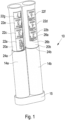
- the dosing device 10 has a first cylindrical body 14a and a second cylindrical body 14b.
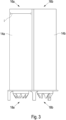
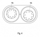
- the two cylindrical bodies 14a, 14b each have a dispensing opening 18a, 18b at their respective distal end, which Figures 3 and 4 These dispensing openings can be closed by a cover cap 15.
- a piston 20a, 20b is inserted into the respective proximal opening of the cylindrical bodies 14a, 14b.
- the two pistons 20a, 20b are only connected at their end opposite the cylindrical bodies 14a, 14b, so that they can be pushed almost completely into the cylindrical bodies 14a, 14b. This displaces the flowable material 12a, 12b that is located in the respective cylindrical body, so that it is dispensed through the dispensing openings 18a, 18b.
- the pistons 20a, 20b each have a series of stop elements 22a - 22g that can be pressed in the radial direction. These are arranged alternately in the axial direction on the first and second pistons 20a, 20b.
- the first stop element 22a is thus pressed in during the first operation so that the two pistons 20a, 20b can be inserted into the cylindrical bodies 14a, 14b by a defined axial distance until the second leg 26b of the second stop element 22b rests on the edge 24b that surrounds the second cylindrical body 14b.
- the double piston 20a, 20b cannot be pushed further into the cylindrical bodies 14a, 14b unless the second stop element 22b is actuated. However, this only occurs during the next operating step, ie when the user wants to apply another dose of the flowable material.
Landscapes
- Engineering & Computer Science (AREA)
- Health & Medical Sciences (AREA)
- Public Health (AREA)
- Mechanical Engineering (AREA)
- Epidemiology (AREA)
- Life Sciences & Earth Sciences (AREA)
- Hydrology & Water Resources (AREA)
- Water Supply & Treatment (AREA)
- Containers And Packaging Bodies Having A Special Means To Remove Contents (AREA)
Description
- Die Erfindung betrifft eine Dosiervorrichtung zum Ausgeben definierter Dosen eines fließfähigen Materials.
- Ein solches Material kann beispielsweise eine klebrige Konsistenz aufweisen, d.h. selbsttätig an einer Oberfläche kleben.
- Es ist bekannt, fließfähige Materialien, beispielsweise Gels, durch Dosiervorrichtungen an der Innenseite einer Toilettenschüssel anzubringen und so eine Reinigung oder Desinfektion der Toilette zu erreichen.
-
EP 2 361 850 B1 beschreibt eine Dosiervorrichtung zur Ausgabe eines fließfähigen Materials auf die Innenseite einer Toilettenschüssel. Hierzu wird ein Kolben in einen zylindrischen Körper eingeführt. Beim Einführen verdrängt der Kolben ein fließfähiges Material, das sich im zylindrischen Körper befindet, so dass dieses über eine Ausgabeöffnung ausgegeben wird. - Nachteilig an dieser Vorrichtung ist, dass sie nur zur Ausgabe eines einzigen fließfähigen Materials geeignet ist.
- Aufgabe der Erfindung ist es, eine Dosiervorrichtung zum Ausgeben definierter Dosen von mindestens zwei fließfähigen Materialien bereitzustellen.
- Die Lösung der Aufgabe erfolgt erfindungsgemäß durch die Merkmale des Anspruchs 1.
- Die erfindungsgemäße Dosiervorrichtung weist zwei zylinderförmige Körper auf, deren Innenraum jeweils einen Hohlraum zur Aufnahme des fließfähigen Materials bildet. Bei diesem fließfähigen Material kann es sich beispielsweise um ein Gel im umgangssprachlichen Sinne oder ein anderes fließfähiges Material mit hoher oder niedriger Viskosität handeln. Wesentlich ist, dass das fließfähige Material derart ausgebildet ist, dass es nicht selbsttätig aus der Dosiervorrichtung heraustritt und ferner eine klebrige Konsistenz aufweist, so dass es beim Applizieren selbsttätig auf der Innenseite einer Toilettenschussel haftet. Ferner kann das Material eine derartige Viskosität aufweisen, dass es nach der Applikation seine Form behält, sofern es nicht durch äußere Einflüsse verformt wird.
- Erfindungsgemäß weist jeder zylindrische Körper ein erstes offenes Ende und diesem gegenüberliegend eine Ausgabeöffnung auf. Die zylindrischen Körper können beispielsweise kreiszylindrisch ausgebildet sein, können jedoch auch andere Zylinderformen aufweisen.
- Die Dosiervorrichtung weist ferner zwei Kolben zum axialen Einführen in das jeweilig erste offene Ende des ersten und zweiten zylindrischen Körpers auf. Das Einführen erfolgt derart, dass das fließfähige Material durch den Kolben verdrängt und aus der Ausgabeöffnung gedrückt wird.
- Die Dosiervorrichtung weist ferner die im Folgenden beschriebenen Elemente auf, um zu gewährleisten, dass der erste und zweite Kolben bei jedem Bedienschritt um ein definiertes Maß in den zylindrischen Körper eingeschoben werden kann, so dass eine definierte Dosis des fließfähigen Materials durch die Ausgabeöffnung des zylindrischen Körpers ausgegeben wird.
- Erfindungsgemäß weist jeder Kolben eindrückbare Anschlagelemente auf. Diese sind in radialer Richtung des Kolbens eindrückbar und mit einem axialen Abstand zueinander angeordnet. Der Begriff "axial" bezieht sich hierbei auf die Axialrichtung des Kolbens, die bevorzugt mit der axialen Richtung des zylinderförmigen Körpers übereinstimmt. Der Kolben weist im Wesentlichen dieselbe Grundform wie der zylinderförmige Körper auf und weist ferner einen etwas reduzierten Durchmesser auf, so dass er beim Einführen in den zylindrischen Körper dessen Innenseite berührt. Der Außendurchmesser der Kolben entspricht somit im Wesentlichen dem Innendurchmesser der zylindrischen Körpers.
- Die eindrückbaren Anschlagelemente sind somit bevorzugt in Längsrichtung des Kolbens angeordnet.
- Erfindungsgemäß erstreckt sich ein Anschlagelement im nicht eingedrückten Zustand in radialer Richtung über den Innendurchmesser des zylindrischen Körpers hinaus und bildet so einen Anschlag für den Rand des zylindrischen Körpers, der das offene Ende des zylindrischen Körpers umgibt. Dies bewirkt, dass der Kolben nicht über diesen Anschlag hinaus in den zylindrischen Körper einführbar ist.
- Im eingedrückten Zustand erstreckt sich ein Anschlagelement in radialer Richtung nicht über den Innendurchmesser des zylindrischen Körpers hinaus, so dass der Kolben über dieses Anschlagelement hinaus in den zylindrischen Körper einführbar ist. Ein eingedrücktes Anschlagelement bildet somit keinen Anschlag.
- Durch die erfindungsgemäße Dosiervorrichtung ist somit ein Ausgeben von zwei verschiedenen fließfähigen Materialien durch eine einzige Dosiervorrichtung möglich. Hierfür muss der Benutzer lediglich die beiden Kolben gemeinsam in axialer Richtung in die jeweiligen zylindrischen Körper hineinschieben. Sodann erfolgt ein gleichzeitiges Ausgeben von jeweils einem fließfähigen Material aus der jeweiligen Ausgebeöffnung des ersten und zweiten zylindrischen Körpers. Beispielsweise ist die Ausgabe von fließfähigen Materialien mit unterschiedlicher Farbe und/oder unterschiedlichen Wirkstoffen möglich. Die erfindungsgemäße Dosiervorrichtung weist hierdurch eine besonders einfache Bedienung auf.
- Es ist erfindungsgemäß vorgesehen, dass die Anschlagelemente des ersten Kolbens in axialer Richtung einen identischen Abstand zueinander aufweisen. Selbiges gilt für die Anschlagelemente des zweiten Kolbens. Der Abstand zwischen zwei benachbarten Anschlagelementen des ersten Kolbens multipliziert mit der Querschnittsfläche des Kolbens ergibt das zweifache Volumen, das von der Dosiervorrichtung als eine Dosis des fließfähigen Materials ausgegeben werden soll. Selbiges gilt auch für die Querschnittsfläche des zweiten Kolbens.
- Es ist bevorzugt, dass die Anschlagelemente des ersten Kolbens gegenüber den Anschlagelementen des zweiten Kolbens in axialer Richtung zueinander versetzt sind. Anders ausgedrückt weisen der erste und der zweite Kolben kein Anschlagelement auf, das in axialer Richtung nicht zueinander versetzt ist. Durch ein abwechselndes Betätigen eines Anschlagelements auf dem ersten und auf dem zweiten Kolben und ein anschließendes Hineinschieben der Kolben bis zum jeweils nächsten Anschlagelement in den jeweiligen zylindrischen Körper wird somit das Ausgeben von gleichbleibenden Dosen zweier fließfähiger Materialien ermöglicht.
- Es ist erfindungsgemäss vorgeshen, dass die Anschlagelemente des ersten Kolbens gegenüber den Anschlagelementen des zweiten Kolbens in axialer Richtung um einen Abstand versetzt sind, der der Hälfte des Abstands zwischen zwei benachbarten Anschlagelementen des ersten oder zweiten Kolbens entspricht. Der Referenzpunkt für den genannten Abstand ist hierbei jeweils die Vorderkante jedes Anschlagelements, die in Richtung in der Ausgabeöffnung zeigt und die in nicht eingedrückten Zustand des Anschlagelements am Rand des zylindrischen Körpers anliegt, so dass der Kolben nicht in den zylindrischen Körper eingeführt werden kann.
- Es ist weiterhin bevorzugt, dass der erste und zweite Kolben derart miteinander verbunden sind, dass sie in axialer Richtung relativ zueinander unbeweglich sind. Sie können somit in axialer Richtung nur gemeinsam bewegt werden.
- Besonders bevorzugt sind der erste und der zweite Kolben einstückig beispielsweise aus einem Kunststoffmaterial ausgebildet.
- Es ist weiterhin bevorzugt, dass der erste und zweite Kolben ausschließlich an ihrem den zylindrischen Körpern abgewandten Ende miteinander verbunden sind. Hierdurch wird es ermöglicht, dass die Kolben nahezu vollständig in die zylindrischen Körper eingeführt werden können.
- Weiterhin ist es bevorzugt, dass der erste und zweite Kolben an seinem dem ersten und zweiten Zylinderkörper zugewandten axialen Ende jeweils eine Dichtungskappe aufweist, durch die ein Verdrängen des fließfähigen Materials beim Vorschieben des Kolbens in den jeweiligen zylindrischen Körper erfolgt. Die Dichtungskappen können einen kreisrunden Querschnitt aufweisen und einen Durchmesser aufweisen, der geringfügig kleiner als der Innendurchmesser des jeweiligen zylindrischen Körpers ist, so dass die Dichtungskappe an ihrem Umfang dichtend an der Innenseite des zylindrischen Körpers anliegt.
- Erfindungsgemäß befinden sich jeweils zwei nacheinander zu bedienende Anschlagelemente auf unterschiedlichen Kolben. Geht man somit von einem Anschlagelement in dem ersten Kolben aus, befindet sich das in axialer Richtung nächste Anschlagelement im zweiten Kolben, woraufhin sich das in axialer Richtung dritte Anschlagelement wieder im ersten Kolben befindet. Dies bedeutet, dass bei jedem Bedienschritt, d.h. bei jedem erneuten Ausgeben einer definierten Dosis des fließfähigen Materials, ein Anschlagelement in einem anderen Kolben betätigt wird. Es findet somit ein abwechselndes Betätigen der Anschlagelemente in den beiden Kolben statt. Das versetzte Anordnen der Anschlagelemente auf den beiden Kolben bietet den Vorteil, dass die Anschlagelemente eine ausreichende Größe aufweisen können, um bequem mit den Fingern eines Benutzers betätigt werden zu können, ohne dass gleichzeitig ein zu großes Einschieben des Kolbens in den jeweiligen zylindrischen Körper verursacht wird. Durch die genannte Ausgestaltung der Anschlagelemente wird beim Betätigen eines jeden Anschlagelements der Kolben um eine Strecke in den jeweiligen zylindrischen Körper eingeführt, die der Hälfte des axialen Versatzes zweier in einem Kolben benachbarten Anschlagelemente entspricht.
- Alternativ zu der Anordnung der Anschlagelemente in zwei Kolben können diese auch in drei oder mehr Kolben angeordnet werden, wobei dann der axiale Versatz zweier in axialer Richtung aufeinanderfolgender Anschlagelemente ein Drittel, ein Viertel usw. des axialen Versatzes zweier in einem Kolben benachbarter Anschlagelemente beträgt.
- Durch diese versetzte Anordnung der Anschlagelemente ist es möglich, einen Kolben und zylinderförmigen Körper mit einem relativ großen Durchmesser zu verwenden, so dass hierin mehr fließfähiges Material aufnehmbar ist.
- Bevorzugt ist eine Seite jedes Anschlagelements mit dem Kolben schwenkbar verbunden, Die gegenüberliegende Seite ist um die mit dem Kolben verbundene Seite in radialer Richtung des Kolbens nach innen schwenkbar. D.h. diese gegenüberliegende Seite kann in den Kolben hineingedrückt werden. Die gegenüberliegende Seite kann beispielsweise durch einen oder zwei Stege lösbar mit dem Kolben verbunden sein. Eine lösbare Verbindung in diesem Zusammenhang bedeutet, dass diese Stege beim erstmaligen Eindrücken des Anschlagelements durchtrennt werden, so dass die Verbindung der gegenüberliegenden Seite mit dem Kolben gelöst wird.
- Weiterhin ist bevorzugt, dass die Anschlagelemente einen L-förmigen Vorsprung aufweisen, der sich in radialer Richtung von den Anschlagelementen nach außen erstreckt. Hierbei ist ein Schenkel des L-förmigen Vorsprungs in den Anschlagelementen des ersten Kolbens in Richtung der Anschlagelemente des zweiten Kolbens angeordnet. Anders ausgedrückt weist somit jedes Anschlagelement einen Vorsprung auf, dessen erster Schenkel in Richtung der der Anschlagelemente des anderen Kolbens angeordnet ist. Der zweite Schenkel des L-förmigen Vorsprungs ist in Richtung des zylindrischen Körpers angeordnet, Der L-förmige Vorsprung dient dazu, dass die Anschlagelemente durch den Benutzer leichter eingedrückt werden können, ohne dass der Daumen des Benutzers von den Anschlagelementen wegrutscht, Gleichzeitig kann der L-förmige Vorsprung als Anschlag bei einem nicht eingedrückten Anschlagelement für den Rand des zylinderförmigen Körpers dienen.
- Der L-förmige Vorsprung soll verhindern, dass ein Anschlagelement durch ein Hineindrücken des Kolbens in den zylindrischen Körper sich eigenständig verformt, ohne durch einen Benutzer betätigt zu werden. Durch den L-förmigen Vorsprung kann somit ein selbsttätiges Hineindrücken eines Anschlagelements verhindert werden, das auftreten kann, wenn der Kolben in den zylindrischen Körper geschoben wird. Um dies zu verhindern, ist der L-förmige Vorsprung derart ausgebildet, dass er sich an einer Stelle des Anschlagelements, beispielsweise etwa in der Mitte des Anschlagelements in Umfangsrichtung betrachtet, in radialer Richtung sprunghaft vom Anschlagelement weg nach oben erstreckt.
- Durch den ersten Schenkel des L-förmigen Vorsprungs, der in Richtung der Anschlagelemente des anderen Kolbens angeordnet ist, kann verhindert werden, dass sich ein eingedrücktes Anschlagelement selbsttätig wieder in radialer Richtung nach außen bewegt und somit ein Einführen des Kolbens in den zylindrischen Körper verhindert.
- Erfindungsgemäß ist weiterhin vorgesehen, dass die zylindrischen Körper mindestens drei Abstandhalter aufweisen, die sich in axialer Richtung von den zylindrischen Körpern weg über die Ausgabeöffnung hinaus erstrecken. Hierdurch entsteht ein Hohlraum in axialer Richtung zwischen dem distalen Ende der Abstandhalter, d.h. dem Ende der Abstandhalter, das vom zylindrischen Körper wegweist, und der Ausgabeöffnung. Diese Abstandhalter dienen dazu, das vordere Ende der Dosiervorrichtung auf die Innenseite einer Toilettenschüssel aufsetzen zu können, so dass ein Abstand in axialer Richtung von der Innenseite der Toilettenschüssel bis zur Ausgabeöffnung eingehalten werden kann. In den hier entstehenden Hohlraum kann das fließfähige Material ausgegeben werden. Es ist somit gewährleistet, dass beim Applizieren des fließfähigen Materials kein Druck durch die Dosiervorrichtung auf das fließfähige Material ausgeübt wird, so dass dieses in einer optisch ansprechenden Form ausgegeben werden kann. Durch die Abstandhalter kann ferner gewährleistet werden, dass die Dosiervorrichtung und insbesondere die Ausgabeöffnungen immer in einem definierten Abstand zur Innenseite der Toilettenschüssel positioniert sind, während das fließfähige Material ausgegeben wird.
- Im Folgenden werden bevorzugte Ausführungsformen der Erfindung anhand von Figuren erläutert. Es zeigen:
- Figur 1
- Eine perspektivische Ansicht einer Ausführungsform der erfindungsgemäßen Dosiervorrichtung
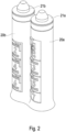
- Figur 2
- eine Ausführungsform des ersten und zweiten Kolbens
- Figur 3
- eine Ausführungsform des ersten und zweiten zylinderförmigen Körpers
- Figur 4
- eine Ansicht auf die Ausgabeöffnungen von unten
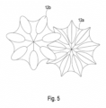
- Figur 5
- eine Darstellung des von der Dosiervorrichtung ausgegebenen fließfähigen Materials.
- Wie in
Figur 1 erkennbar, weist die Dosiervorrichtung 10 einen ersten zylindrischen Körper 14a und einen zweiten zylindrischen Körper 14b auf. Die beiden zylindrischen Körper 14a, 14b weisen an ihrem jeweiligen distalen Ende jeweils eine Ausgabeöffnung 18a, 18b auf, die in denFiguren 3 und4 dargestellt sind. Diese Ausgabeöffnungen können durch eine Abdeckkappe 15 verschlossen werden. - Wie weiterhin in
Figur 1 erkennbar, wird in die jeweilige proximale Öffnung der zylindrischen Körper 14a, 14b jeweils ein Kolben 20a, 20b eingeführt. Die beiden Kolben 20a, 20b sind ausschließlich an ihrem den zylindrischen Körper 14a, 14b gegenüberliegenden Ende verbunden, so dass sie nahezu vollständig in die zylindrischen Körper 14a, 14b eingeschoben werden können. Hierdurch erfolgt ein Verdrängen des fließfähigen Materials 12a, 12b, das sich in dem jeweiligen zylinderförmigen Körper befindet, so dass es durch die Ausgabeöffnungen 18a, 18b ausgegeben wird. - Um sicherzustellen, dass bei jedem Bedienschritt jeweils eine definierte Dosis der fließfähigen Materialien ausgegeben wird, weisen bei den Kolben 20a, 20b jeweils eine Reihe von Anschlagelementen 22a - 22g auf, die in radialer Richtung eindrückbar sind. Diese sind auf dem ersten und auf dem zweiten Kolben 20a, 20b in axialer Richtung abwechselnd angeordnet. Es wird somit bei der ersten Bedienung das erste Anschlagelement 22a eingedrückt, so dass die beiden Kolben 20a, 20b um einen definierten axialen Abstand in die zylinderförmigen Körper 14a, 14b eingeführt werden können, bis der zweite Schenkel 26b des zweiten Anschlagelements 22b am Rand 24b anliegt, der den zweiten zylindrischen Körper 14b umgibt. Der Doppelkolben 20a, 20b kann nicht weiter in die zylindrischen Körper 14a, 14b eingeschoben werden, sofern nicht das zweite Anschlagelement 22b betätigt wird. Dies erfolgt allerdings erst beim nächsten Bedienschritt, d.h. wenn der Nutzer eine weitere Dosis des fließfähigen Materials applizieren möchte.
- Entsprechend erfolgt die weitere Bedienung durch abwechselndes Betätigen der weiteren Anschlagelemente 22c - 22g.
- In
Figur 2 sind die beiden Kolben 20a, 20b erneut dargestellt.
Claims (6)
- Dosiervorrichtung zum Ausgeben definierter Dosen eines fließfähigen Materials (12a, 12b),mit zwei zylinderförmigen Körpern (14a, 14b), deren Innenraum jeweils einen Hohlraum zur Aufnahme des fließfähigen Materials (12a, 12b) bildet,wobei jeder zylindrische Körper (14a, 14b) ein erstes offenes Ende (16a, 16b) und diesem gegenüberliegend eine Ausgabeöffnung (18a, 18b) aufweist,wobei die Dosiervorrichtung (10) ferner aufweist: zwei Kolben (20a, 20b) zum axialen Einführen jeweils in das erste offene Ende (16a, 16b) eines zylindrischen Körpers (14a, 14b) derart, dass das fließfähige Material (12a, 12b) durch die Kolben (20a, 20b) verdrängt und aus den Ausgabeöffnungen (18a, 18b) gedrückt wird,dadurch gekennzeichnet, dass jeder zylinderförmige Körper (14a, 14b) Elemente aufweist, um zu gewährleisten, dass der Kolben (20) bei jedem Bedienschritt um ein definiertes Maß in den zylindrischen Körper (14a, 14b) eingeschoben werden kann, so dass eine definierte Dosis des fließfähigen Materials (12a, 12b) durch die Ausgabeöffnungen (18a, 18b) der zylindrischen Körper (14a, 14b) ausgegeben wird,wobei die Dosiervorrichtung hierzu in jedem Kolben (20a, 20b) in radialer Richtung eindrückbare Anschlagelemente (22a bis 22g) aufweist, die mit einem axialen Abstand zueinander angeordnet sind,wobei sich ein Anschlagelement (22a) im nicht eingedrückten Zustand in radialer Richtung über den Innendurchmesser (i) des zylindrischen Körpers (14) hinaus erstreckt und so einen Anschlag für den jeweiligen Rand (24a, 24b) der zylindrischen Körpers (14a, 14b), der sein offenes Ende (16a, 16b) umgibt, bildet derart, dass der Kolben (20a, 20b) nicht über diesen Anschlag hinaus in den zylindrischen Körper (14a, 14b) einführbar ist, und sich ein Anschlagelement (22a) im eingedrückten Zustand in radialer Richtung nicht über den Innendurchmesser (i) des zylindrischen Körpers (14) hinaus erstreckt, so dass der Kolben (20) über dieses Anschlagelement (22a) hinaus in den zylindrischen Körper (14) einführbar ist,die Anschlagelemente (22a, 22c, 22e, 22g) des ersten Kolbens (20a) in axialer Richtung einen identischen Abstand zueinander aufweisen,die Anschlagelemente (22b, 22d, 22f) des zweiten Kolbens (20b) in axialer Richtung einen identischen Abstand zueinander aufweisen,wobei der Abstand zwischen zwei benachbarten Anschlagelementen (22a, 22c) des ersten Kolbens (20a) oder des zweiten Kolbens (20b) multipliziert mit der Querschnittsfläche des jeweiligen Kolbens das zweifache Volumen ergibt, das von der Dosiervorrichtung als eine Dosis ausgegeben werden soll,wobei die Anschlagelemente (22a, 22c, 22e, 22g) des ersten Kolbens (20a) gegenüber den Anschlagelementen (22b, 22d, 22f) des zweiten Kolbens (20b) in axialer Richtung um einen Abstand versetzt sind, der der Hälfte des Abstandes zwischen zwei benachbarten Anschlagelementen des ersten oder zweiten Kolbens (20a, 20b) entspricht.
- Dosiervorrichtung nach Anspruch 1, dadurch gekennzeichnet, dass die Anschlagelemente (22a, 22c, 22e, 22g) des ersten Kolbens (20a) gegenüber den Anschlagelementen (22b, 22d, 22f) des zweiten Kolbens (20b) in axialer Richtung zueinander versetzt sind.
- Dosiervorrichtung nach Ansprüchen 1 bis 2, dadurch gekennzeichnet, dass der erste und zweite Kolben (20a, 20b) derart miteinander verbunden sind, dass sie in axialer Richtung relativ zueinander unbeweglich sind.
- Dosiervorrichtung nach Ansprüchen 1 bis 2, dadurch gekennzeichnet, dass der erste und zweite Kolben (20a, 20b) einstückig ausgebildet sind.
- Dosiervorrichtung nach Anspruch 4, dadurch gekennzeichnet, dass der erste und zweite Kolben (20a, 20b) ausschließlich an ihren den zylindrischen Körpern (14a, 14b) abgewandten axialen Ende miteinander verbunden sind.
- Dosiervorrichtung nach Ansprüchen 1- 5, dadurch gekennzeichnet, dass der erste und zweite Kolben (20a, 20b) an seinem dem ersten und zweiten zylindrischen Körper (14a, 14b) zugewandten axialen Ende jeweils eine Dichtungskappe (21a, 21b) aufweist, durch die ein Verdrängen des fließfähigen Materials beim Vorschieben des Kolbens (20a, 20b) in den jeweiligen zylindrischen Körper (14a, 14b) erfolgt.
Priority Applications (5)
| Application Number | Priority Date | Filing Date | Title |
|---|---|---|---|
| ES19216092T ES2989217T3 (es) | 2019-12-13 | 2019-12-13 | Dispositivo dosificador |
| PT192160927T PT3835231T (pt) | 2019-12-13 | 2019-12-13 | Dispositivo de dosagem |
| EP19216092.7A EP3835231B1 (de) | 2019-12-13 | 2019-12-13 | Dosiervorrichtung |
| PL19216092.7T PL3835231T3 (pl) | 2019-12-13 | 2019-12-13 | Urządzenie dozujące |
| PCT/EP2020/082468 WO2021115742A1 (de) | 2019-12-13 | 2020-11-18 | Dosiervorrichtung |
Applications Claiming Priority (1)
| Application Number | Priority Date | Filing Date | Title |
|---|---|---|---|
| EP19216092.7A EP3835231B1 (de) | 2019-12-13 | 2019-12-13 | Dosiervorrichtung |
Publications (2)
| Publication Number | Publication Date |
|---|---|
| EP3835231A1 EP3835231A1 (de) | 2021-06-16 |
| EP3835231B1 true EP3835231B1 (de) | 2024-08-28 |
Family
ID=69105683
Family Applications (1)
| Application Number | Title | Priority Date | Filing Date |
|---|---|---|---|
| EP19216092.7A Active EP3835231B1 (de) | 2019-12-13 | 2019-12-13 | Dosiervorrichtung |
Country Status (5)
| Country | Link |
|---|---|
| EP (1) | EP3835231B1 (de) |
| ES (1) | ES2989217T3 (de) |
| PL (1) | PL3835231T3 (de) |
| PT (1) | PT3835231T (de) |
| WO (1) | WO2021115742A1 (de) |
Family Cites Families (3)
| Publication number | Priority date | Publication date | Assignee | Title |
|---|---|---|---|---|
| DE102010028352A1 (de) * | 2010-04-29 | 2011-11-03 | Henkel Ag & Co. Kgaa | Applikator für gelförmige Produkte, insbesondere ein WC-Reinigungsprodukt |
| RS53241B (sr) * | 2011-04-20 | 2014-08-29 | Tomil S.R.O. | Merni uređaj |
| PL3090962T3 (pl) * | 2015-05-06 | 2018-05-30 | Tomil S.R.O. | Dozownik środka czyszczącego |
-
2019
- 2019-12-13 EP EP19216092.7A patent/EP3835231B1/de active Active
- 2019-12-13 PL PL19216092.7T patent/PL3835231T3/pl unknown
- 2019-12-13 PT PT192160927T patent/PT3835231T/pt unknown
- 2019-12-13 ES ES19216092T patent/ES2989217T3/es active Active
-
2020
- 2020-11-18 WO PCT/EP2020/082468 patent/WO2021115742A1/de not_active Ceased
Also Published As
| Publication number | Publication date |
|---|---|
| ES2989217T3 (es) | 2024-11-25 |
| WO2021115742A1 (de) | 2021-06-17 |
| PL3835231T3 (pl) | 2025-02-17 |
| EP3835231A1 (de) | 2021-06-16 |
| PT3835231T (pt) | 2024-10-11 |
Similar Documents
| Publication | Publication Date | Title |
|---|---|---|
| EP2361850B1 (de) | Dosiervorrichtung | |
| DE69612483T2 (de) | Handbetätigbare austragevorrichtung mit kraftbegrenzungskupplung | |
| EP1745855B1 (de) | Spender zum ggf. zerstäubten Ausbringen eines insbesondere flüssigen Mediums aus einem Behältnis | |
| EP2804504B1 (de) | Medienspender | |
| EP2396237B1 (de) | Austragvorrichtung mit tube | |
| EP3102254B1 (de) | Injektionsgerät | |
| DE10206207B4 (de) | Kuchenteigspender | |
| EP2520194B1 (de) | Kosmetikeinheit mit blockierbarem Rastverschluss | |
| EP3452229B1 (de) | Flüssigkeitsspender | |
| DE2319175A1 (de) | Detail-kolbenpipette | |
| EP3102257B1 (de) | Injektionsgerät | |
| DE2324296A1 (de) | Mischbehaelter fuer dentalpraeparate | |
| EP1186312A2 (de) | Austragsvorrichtung für Medien | |
| EP2680910B1 (de) | Vorrichtung zur betätigung einer karpule | |
| EP1447140A2 (de) | Austragvorrichtung zur manuellen Erzeugung eines Volumenstroms | |
| EP2688678A1 (de) | Spender | |
| DE102007054019A1 (de) | Injektionsvorrichtung mit betätigungsaktivierter Kupplung | |
| DE3911089A1 (de) | Dosiervorrichtung | |
| EP3416751B1 (de) | Vorrichtung zum aufbringen von kleb- und oder dichtstoff | |
| EP2158136B1 (de) | Vorrichtung zum austragen einer fliessfähigen substanz | |
| DE20319464U1 (de) | Kolben für eine Kartusche zum Aufbewahren und Auspressen von pastösen Substanzen und Kartusche mit demselben | |
| EP3835231A1 (de) | Dosiervorrichtung | |
| DE69033447T2 (de) | Dentale Zusammensetzung | |
| EP2885088B1 (de) | Austragvorrichtung | |
| EP2835321B1 (de) | Behälter zum Dosieren eines fließfähigen Stoffes |
Legal Events
| Date | Code | Title | Description |
|---|---|---|---|
| PUAI | Public reference made under article 153(3) epc to a published international application that has entered the european phase |
Free format text: ORIGINAL CODE: 0009012 |
|
| STAA | Information on the status of an ep patent application or granted ep patent |
Free format text: STATUS: THE APPLICATION HAS BEEN PUBLISHED |
|
| AK | Designated contracting states |
Kind code of ref document: A1 Designated state(s): AL AT BE BG CH CY CZ DE DK EE ES FI FR GB GR HR HU IE IS IT LI LT LU LV MC MK MT NL NO PL PT RO RS SE SI SK SM TR |
|
| STAA | Information on the status of an ep patent application or granted ep patent |
Free format text: STATUS: REQUEST FOR EXAMINATION WAS MADE |
|
| 17P | Request for examination filed |
Effective date: 20211216 |
|
| RBV | Designated contracting states (corrected) |
Designated state(s): AL AT BE BG CH CY CZ DE DK EE ES FI FR GB GR HR HU IE IS IT LI LT LU LV MC MK MT NL NO PL PT RO RS SE SI SK SM TR |
|
| STAA | Information on the status of an ep patent application or granted ep patent |
Free format text: STATUS: EXAMINATION IS IN PROGRESS |
|
| 17Q | First examination report despatched |
Effective date: 20230804 |
|
| GRAP | Despatch of communication of intention to grant a patent |
Free format text: ORIGINAL CODE: EPIDOSNIGR1 |
|
| STAA | Information on the status of an ep patent application or granted ep patent |
Free format text: STATUS: GRANT OF PATENT IS INTENDED |
|
| INTG | Intention to grant announced |
Effective date: 20240219 |
|
| GRAS | Grant fee paid |
Free format text: ORIGINAL CODE: EPIDOSNIGR3 |
|
| RAP3 | Party data changed (applicant data changed or rights of an application transferred) |
Owner name: TOMIL S.R.O. |
|
| RIN1 | Information on inventor provided before grant (corrected) |
Inventor name: MUELLER, TOMAS |
|
| GRAA | (expected) grant |
Free format text: ORIGINAL CODE: 0009210 |
|
| STAA | Information on the status of an ep patent application or granted ep patent |
Free format text: STATUS: THE PATENT HAS BEEN GRANTED |
|
| P01 | Opt-out of the competence of the unified patent court (upc) registered |
Free format text: CASE NUMBER: APP_38880/2024 Effective date: 20240628 |
|
| AK | Designated contracting states |
Kind code of ref document: B1 Designated state(s): AL AT BE BG CH CY CZ DE DK EE ES FI FR GB GR HR HU IE IS IT LI LT LU LV MC MK MT NL NO PL PT RO RS SE SI SK SM TR |
|
| REG | Reference to a national code |
Ref country code: GB Ref legal event code: FG4D Free format text: NOT ENGLISH |
|
| REG | Reference to a national code |
Ref country code: CH Ref legal event code: EP |
|
| REG | Reference to a national code |
Ref country code: DE Ref legal event code: R096 Ref document number: 502019011983 Country of ref document: DE |
|
| REG | Reference to a national code |
Ref country code: IE Ref legal event code: FG4D Free format text: LANGUAGE OF EP DOCUMENT: GERMAN |
|
| REG | Reference to a national code |
Ref country code: PT Ref legal event code: SC4A Ref document number: 3835231 Country of ref document: PT Date of ref document: 20241011 Kind code of ref document: T Free format text: AVAILABILITY OF NATIONAL TRANSLATION Effective date: 20241007 |
|
| REG | Reference to a national code |
Ref country code: NL Ref legal event code: FP |
|
| REG | Reference to a national code |
Ref country code: ES Ref legal event code: FG2A Ref document number: 2989217 Country of ref document: ES Kind code of ref document: T3 Effective date: 20241125 |
|
| REG | Reference to a national code |
Ref country code: LT Ref legal event code: MG9D |
|
| PG25 | Lapsed in a contracting state [announced via postgrant information from national office to epo] |
Ref country code: NO Free format text: LAPSE BECAUSE OF FAILURE TO SUBMIT A TRANSLATION OF THE DESCRIPTION OR TO PAY THE FEE WITHIN THE PRESCRIBED TIME-LIMIT Effective date: 20241128 |
|
| PG25 | Lapsed in a contracting state [announced via postgrant information from national office to epo] |
Ref country code: GR Free format text: LAPSE BECAUSE OF FAILURE TO SUBMIT A TRANSLATION OF THE DESCRIPTION OR TO PAY THE FEE WITHIN THE PRESCRIBED TIME-LIMIT Effective date: 20241129 Ref country code: FI Free format text: LAPSE BECAUSE OF FAILURE TO SUBMIT A TRANSLATION OF THE DESCRIPTION OR TO PAY THE FEE WITHIN THE PRESCRIBED TIME-LIMIT Effective date: 20240828 |
|
| PG25 | Lapsed in a contracting state [announced via postgrant information from national office to epo] |
Ref country code: BG Free format text: LAPSE BECAUSE OF FAILURE TO SUBMIT A TRANSLATION OF THE DESCRIPTION OR TO PAY THE FEE WITHIN THE PRESCRIBED TIME-LIMIT Effective date: 20240828 |
|
| PG25 | Lapsed in a contracting state [announced via postgrant information from national office to epo] |
Ref country code: LV Free format text: LAPSE BECAUSE OF FAILURE TO SUBMIT A TRANSLATION OF THE DESCRIPTION OR TO PAY THE FEE WITHIN THE PRESCRIBED TIME-LIMIT Effective date: 20240828 |
|
| PG25 | Lapsed in a contracting state [announced via postgrant information from national office to epo] |
Ref country code: IS Free format text: LAPSE BECAUSE OF FAILURE TO SUBMIT A TRANSLATION OF THE DESCRIPTION OR TO PAY THE FEE WITHIN THE PRESCRIBED TIME-LIMIT Effective date: 20241228 |
|
| PG25 | Lapsed in a contracting state [announced via postgrant information from national office to epo] |
Ref country code: HR Free format text: LAPSE BECAUSE OF FAILURE TO SUBMIT A TRANSLATION OF THE DESCRIPTION OR TO PAY THE FEE WITHIN THE PRESCRIBED TIME-LIMIT Effective date: 20240828 |
|
| PG25 | Lapsed in a contracting state [announced via postgrant information from national office to epo] |
Ref country code: RS Free format text: LAPSE BECAUSE OF FAILURE TO SUBMIT A TRANSLATION OF THE DESCRIPTION OR TO PAY THE FEE WITHIN THE PRESCRIBED TIME-LIMIT Effective date: 20241128 |
|
| PG25 | Lapsed in a contracting state [announced via postgrant information from national office to epo] |
Ref country code: RS Free format text: LAPSE BECAUSE OF FAILURE TO SUBMIT A TRANSLATION OF THE DESCRIPTION OR TO PAY THE FEE WITHIN THE PRESCRIBED TIME-LIMIT Effective date: 20241128 Ref country code: NO Free format text: LAPSE BECAUSE OF FAILURE TO SUBMIT A TRANSLATION OF THE DESCRIPTION OR TO PAY THE FEE WITHIN THE PRESCRIBED TIME-LIMIT Effective date: 20241128 Ref country code: LV Free format text: LAPSE BECAUSE OF FAILURE TO SUBMIT A TRANSLATION OF THE DESCRIPTION OR TO PAY THE FEE WITHIN THE PRESCRIBED TIME-LIMIT Effective date: 20240828 Ref country code: IS Free format text: LAPSE BECAUSE OF FAILURE TO SUBMIT A TRANSLATION OF THE DESCRIPTION OR TO PAY THE FEE WITHIN THE PRESCRIBED TIME-LIMIT Effective date: 20241228 Ref country code: HR Free format text: LAPSE BECAUSE OF FAILURE TO SUBMIT A TRANSLATION OF THE DESCRIPTION OR TO PAY THE FEE WITHIN THE PRESCRIBED TIME-LIMIT Effective date: 20240828 Ref country code: GR Free format text: LAPSE BECAUSE OF FAILURE TO SUBMIT A TRANSLATION OF THE DESCRIPTION OR TO PAY THE FEE WITHIN THE PRESCRIBED TIME-LIMIT Effective date: 20241129 Ref country code: FI Free format text: LAPSE BECAUSE OF FAILURE TO SUBMIT A TRANSLATION OF THE DESCRIPTION OR TO PAY THE FEE WITHIN THE PRESCRIBED TIME-LIMIT Effective date: 20240828 Ref country code: BG Free format text: LAPSE BECAUSE OF FAILURE TO SUBMIT A TRANSLATION OF THE DESCRIPTION OR TO PAY THE FEE WITHIN THE PRESCRIBED TIME-LIMIT Effective date: 20240828 |
|
| PG25 | Lapsed in a contracting state [announced via postgrant information from national office to epo] |
Ref country code: SM Free format text: LAPSE BECAUSE OF FAILURE TO SUBMIT A TRANSLATION OF THE DESCRIPTION OR TO PAY THE FEE WITHIN THE PRESCRIBED TIME-LIMIT Effective date: 20240828 Ref country code: DK Free format text: LAPSE BECAUSE OF FAILURE TO SUBMIT A TRANSLATION OF THE DESCRIPTION OR TO PAY THE FEE WITHIN THE PRESCRIBED TIME-LIMIT Effective date: 20240828 |
|
| PG25 | Lapsed in a contracting state [announced via postgrant information from national office to epo] |
Ref country code: EE Free format text: LAPSE BECAUSE OF FAILURE TO SUBMIT A TRANSLATION OF THE DESCRIPTION OR TO PAY THE FEE WITHIN THE PRESCRIBED TIME-LIMIT Effective date: 20240828 |
|
| PG25 | Lapsed in a contracting state [announced via postgrant information from national office to epo] |
Ref country code: SK Free format text: LAPSE BECAUSE OF FAILURE TO SUBMIT A TRANSLATION OF THE DESCRIPTION OR TO PAY THE FEE WITHIN THE PRESCRIBED TIME-LIMIT Effective date: 20240828 |
|
| REG | Reference to a national code |
Ref country code: DE Ref legal event code: R097 Ref document number: 502019011983 Country of ref document: DE |
|
| PLBE | No opposition filed within time limit |
Free format text: ORIGINAL CODE: 0009261 |
|
| STAA | Information on the status of an ep patent application or granted ep patent |
Free format text: STATUS: NO OPPOSITION FILED WITHIN TIME LIMIT |
|
| PG25 | Lapsed in a contracting state [announced via postgrant information from national office to epo] |
Ref country code: MC Free format text: LAPSE BECAUSE OF FAILURE TO SUBMIT A TRANSLATION OF THE DESCRIPTION OR TO PAY THE FEE WITHIN THE PRESCRIBED TIME-LIMIT Effective date: 20240828 |
|
| 26N | No opposition filed |
Effective date: 20250530 |
|
| PG25 | Lapsed in a contracting state [announced via postgrant information from national office to epo] |
Ref country code: LU Free format text: LAPSE BECAUSE OF NON-PAYMENT OF DUE FEES Effective date: 20241213 |
|
| PG25 | Lapsed in a contracting state [announced via postgrant information from national office to epo] |
Ref country code: SE Free format text: LAPSE BECAUSE OF FAILURE TO SUBMIT A TRANSLATION OF THE DESCRIPTION OR TO PAY THE FEE WITHIN THE PRESCRIBED TIME-LIMIT Effective date: 20240828 |
|
| PG25 | Lapsed in a contracting state [announced via postgrant information from national office to epo] |
Ref country code: IE Free format text: LAPSE BECAUSE OF NON-PAYMENT OF DUE FEES Effective date: 20241213 |
|
| REG | Reference to a national code |
Ref country code: CH Ref legal event code: U11 Free format text: ST27 STATUS EVENT CODE: U-0-0-U10-U11 (AS PROVIDED BY THE NATIONAL OFFICE) Effective date: 20260101 |
|
| PGFP | Annual fee paid to national office [announced via postgrant information from national office to epo] |
Ref country code: DE Payment date: 20251029 Year of fee payment: 7 |
|
| PGFP | Annual fee paid to national office [announced via postgrant information from national office to epo] |
Ref country code: GB Payment date: 20251218 Year of fee payment: 7 |
|
| PGFP | Annual fee paid to national office [announced via postgrant information from national office to epo] |
Ref country code: PT Payment date: 20251211 Year of fee payment: 7 Ref country code: AT Payment date: 20251215 Year of fee payment: 7 |
|
| PGFP | Annual fee paid to national office [announced via postgrant information from national office to epo] |
Ref country code: NL Payment date: 20251217 Year of fee payment: 7 Ref country code: FR Payment date: 20251218 Year of fee payment: 7 |
|
| PGFP | Annual fee paid to national office [announced via postgrant information from national office to epo] |
Ref country code: BE Payment date: 20251218 Year of fee payment: 7 |
|
| PGFP | Annual fee paid to national office [announced via postgrant information from national office to epo] |
Ref country code: CZ Payment date: 20251128 Year of fee payment: 7 |
|
| PGFP | Annual fee paid to national office [announced via postgrant information from national office to epo] |
Ref country code: PL Payment date: 20251203 Year of fee payment: 7 |
|
| PGFP | Annual fee paid to national office [announced via postgrant information from national office to epo] |
Ref country code: RO Payment date: 20251209 Year of fee payment: 7 |
|
| PGFP | Annual fee paid to national office [announced via postgrant information from national office to epo] |
Ref country code: ES Payment date: 20260119 Year of fee payment: 7 |
|
| PGFP | Annual fee paid to national office [announced via postgrant information from national office to epo] |
Ref country code: IT Payment date: 20251231 Year of fee payment: 7 |
|
| PGFP | Annual fee paid to national office [announced via postgrant information from national office to epo] |
Ref country code: CH Payment date: 20260101 Year of fee payment: 7 |