EP3835510B1 - Handlaufvorrichtung für geländer - Google Patents
Handlaufvorrichtung für geländer Download PDFInfo
- Publication number
- EP3835510B1 EP3835510B1 EP20212764.3A EP20212764A EP3835510B1 EP 3835510 B1 EP3835510 B1 EP 3835510B1 EP 20212764 A EP20212764 A EP 20212764A EP 3835510 B1 EP3835510 B1 EP 3835510B1
- Authority
- EP
- European Patent Office
- Prior art keywords
- rail
- claw
- handrail device
- upright
- median plane
- Prior art date
- Legal status (The legal status is an assumption and is not a legal conclusion. Google has not performed a legal analysis and makes no representation as to the accuracy of the status listed.)
- Active
Links
Images


Classifications
-
- E—FIXED CONSTRUCTIONS
- E04—BUILDING
- E04F—FINISHING WORK ON BUILDINGS, e.g. STAIRS, FLOORS
- E04F11/00—Stairways, ramps, or like structures; Balustrades; Handrails
- E04F11/18—Balustrades; Handrails
- E04F11/181—Balustrades
- E04F11/1817—Connections therefor
-
- F—MECHANICAL ENGINEERING; LIGHTING; HEATING; WEAPONS; BLASTING
- F16—ENGINEERING ELEMENTS AND UNITS; GENERAL MEASURES FOR PRODUCING AND MAINTAINING EFFECTIVE FUNCTIONING OF MACHINES OR INSTALLATIONS; THERMAL INSULATION IN GENERAL
- F16B—DEVICES FOR FASTENING OR SECURING CONSTRUCTIONAL ELEMENTS OR MACHINE PARTS TOGETHER, e.g. NAILS, BOLTS, CIRCLIPS, CLAMPS, CLIPS OR WEDGES; JOINTS OR JOINTING
- F16B2/00—Friction-grip releasable fastenings
- F16B2/02—Clamps, i.e. with gripping action effected by positive means other than the inherent resistance to deformation of the material of the fastening
- F16B2/06—Clamps, i.e. with gripping action effected by positive means other than the inherent resistance to deformation of the material of the fastening external, i.e. with contracting action
- F16B2/10—Clamps, i.e. with gripping action effected by positive means other than the inherent resistance to deformation of the material of the fastening external, i.e. with contracting action using pivoting jaws
-
- F—MECHANICAL ENGINEERING; LIGHTING; HEATING; WEAPONS; BLASTING
- F16—ENGINEERING ELEMENTS AND UNITS; GENERAL MEASURES FOR PRODUCING AND MAINTAINING EFFECTIVE FUNCTIONING OF MACHINES OR INSTALLATIONS; THERMAL INSULATION IN GENERAL
- F16B—DEVICES FOR FASTENING OR SECURING CONSTRUCTIONAL ELEMENTS OR MACHINE PARTS TOGETHER, e.g. NAILS, BOLTS, CIRCLIPS, CLAMPS, CLIPS OR WEDGES; JOINTS OR JOINTING
- F16B7/00—Connections of rods or tubes, e.g. of non-circular section, mutually, including resilient connections
- F16B7/04—Clamping or clipping connections
- F16B7/044—Clamping or clipping connections for rods or tubes being in angled relationship
- F16B7/048—Clamping or clipping connections for rods or tubes being in angled relationship for rods or for tubes without using the innerside thereof
- F16B7/0486—Clamping or clipping connections for rods or tubes being in angled relationship for rods or for tubes without using the innerside thereof forming an abutting connection of at least one tube
-
- F—MECHANICAL ENGINEERING; LIGHTING; HEATING; WEAPONS; BLASTING
- F16—ENGINEERING ELEMENTS AND UNITS; GENERAL MEASURES FOR PRODUCING AND MAINTAINING EFFECTIVE FUNCTIONING OF MACHINES OR INSTALLATIONS; THERMAL INSULATION IN GENERAL
- F16B—DEVICES FOR FASTENING OR SECURING CONSTRUCTIONAL ELEMENTS OR MACHINE PARTS TOGETHER, e.g. NAILS, BOLTS, CIRCLIPS, CLAMPS, CLIPS OR WEDGES; JOINTS OR JOINTING
- F16B7/00—Connections of rods or tubes, e.g. of non-circular section, mutually, including resilient connections
- F16B7/18—Connections of rods or tubes, e.g. of non-circular section, mutually, including resilient connections using screw-thread elements
-
- E—FIXED CONSTRUCTIONS
- E04—BUILDING
- E04F—FINISHING WORK ON BUILDINGS, e.g. STAIRS, FLOORS
- E04F11/00—Stairways, ramps, or like structures; Balustrades; Handrails
- E04F11/18—Balustrades; Handrails
- E04F11/181—Balustrades
- E04F11/1817—Connections therefor
- E04F2011/1819—Connections therefor between balustrade posts and horizontal or sloping balustrade members
- E04F2011/1821—Connections therefor between balustrade posts and horizontal or sloping balustrade members between balustrade posts and handrails
Definitions
- the invention relates to a handrail device for guardrails.
- a handrail device comprising a rail intended to form a handrail and a bracket provided for fixing the rail to an upright, and more precisely to an upper (or high) end of the upright.
- a guardrail generally extends along the edges of a terrace or roof, or along an area of limited access, and includes a succession of uprights fixed to a structure by means of shoes.
- the handrails are conventionally designed to be grasped with the whole hand in order to ensure the maintenance of one's balance and facilitate progression, and are also obviously designed to form an upper barrier ensuring protection in order to avoid any accidental fall or accidental access to a dangerous area.
- a handrail device for guardrail comprising a rail intended to form a handrail and a support portion provided for fixing the rail to an upright, where this support portion comprises two arms, including a fixed arm which comes from the material with the amount and a detachable arm secured to a detachable part which is fixed to the amount by a screw.
- assembly is carried out as follows: the rail is slid onto the fixed arm in a groove provided on the underside of the rail, in the absence of the detachable arm, then the detachable part and the arm detachable are slipped into another groove before being fixed by the screw.
- Such a solution is however problematic, because it requires sliding the rail on the fixed arm, then sliding the detachable arm in the rail, which requires longitudinal availability for these two sliding movements, which is strictly impossible when the guard -body is positioned between two walls for example.
- the invention proposes clamping in longitudinal grooves provided on the underside of the rail, which allows the top of the rail to be left free and continuous, the jaws of the stirrup thus not hindering the passage of a hand . Furthermore, assembly is easily done by placing the rail on the stirrup in a loose configuration, then tightening the rail between the two jaws.
- two jaws correspond to the classic definition covering two articulated parts which can be moved away from or brought closer to each other in particular in order to grasp or immobilize an object, in this case two articulated jaws which can be moved away or closer to each other in order to grip and immobilize the rail in its longitudinal grooves.
- the fixation on the amount is carried out by means of the two beveled pieces (or wedge-shaped pieces) which tighten inside the amount and therefore in the extension of the amount.
- the two beveled parts come to rest on the one hand against each other by their respective inclined surfaces, and on the other hand to rest against the internal wall of the upright following relative sliding of the beveled parts the along their inclined surfaces; this sliding leading to a spacing of the two beveled pieces so that the latter press against the internal wall of the upright and thus lock in force in the upright.
- Such a fixing means has the advantage of simplifying and saving time in assembly/disassembly; the assembly operation consisting for example of simply positioning the two beveled pieces in the corresponding profile, without the need for centering or indexing, and then sliding the two beveled pieces and locking them by force inside the amount.
- first beveled part is not a floating part because it is secured to the base of the first jaw while the second beveled part is able to slide relative to said first beveled part; these two beveled pieces being connected together by the actuation means in order to lock the two beveled pieces in the amount.
- the actuation means comprises a threaded orifice provided in the second beveled part, and an actuation screw passing through the base of the first jaw to cooperate by screwing with said threaded orifice to move said second beveled part in sliding relative to the first beveled piece in order to bring the second beveled piece closer to the base and thus lock the beveled pieces inside the opening made in the upper end of the upright.
- the actuation means is produced in the form of an actuation screw, where the actuation screw is easily accessible from the outside; said actuating screw having a screw head projecting outside the upright for easy access to a screwdriving tool.
- an actuation means easily accessible from the outside to allow simple and rapid locking of the two beveled parts in the amount.
- This actuating screw advantageously extends along the main axis of the upright (main axis which is vertical when the upright is vertical), so that no part (such as a rivet) passes through the wall of the upright.
- the base has a lateral portion extending facing the rear face of the second jaw, so that the actuating screw passes through this lateral portion so that the actuating screw and the clamping screw are arranged on the same side opposite the first median plane.
- the lower portion of the external peripheral face of the beam has a support zone extending between the two longitudinal grooves, said support zone coming to bear on the internal clamping faces of the two jaws in configuration tight.
- the longitudinal grooves are provided at a predefined distance, measured in the first median plane from the low point, where this distance is less than or equal to 0.3 times the height of the rail.
- the smooth 4 extends along a longitudinal axis 40 and is for example in the form of a profile, for example of a generally circular section of given diameter.
- the clamping jaw 510 and the base 513 are integral with each other, and are for example made in one piece.
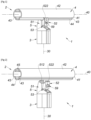
- the tightening screw 59 maintains the second jaw 52 in the loosened position, preventing it from tilting under its own weight, thus allowing the smooth 4 to be placed between the two jaws 51, 52 without it risking falling, as visible on the Figure 4 .
- the two jaws 51, 52 define a sort of “U”-shaped channel bordered on the right and left by the hooks 512, 522, which allows the introduction of the rail 4 while preventing its fall.
- the first beveled part 61 and the second beveled part 62 respectively have inclined surfaces 610, 620 that are antagonistic and flat so that, in position on the upright 3, the first beveled part 61 and the second beveled part 62 are in support of one another. against each other by their respective inclined surfaces 610, 620 and are shaped to slide relative to each other and to be forcefully locked by spacing inside the upright 3.
- the second beveled part 62 has its inclined surface 620 bearing against the inclined surface 610 of the first beveled part 61, where this second beveled part 62 is able to slide relative to the first beveled part 61 along their inclined surfaces 610, 620 respective.
- the sliding of the second beveled part 62 relative to the first beveled part 61 leads to the reduction or increase of the transverse dimensions (dimensions measured in a plane orthogonal to the main axis 30) of the assembly formed by these two parts beveled 61, 62, following the direction of sliding.
- the distance of the second beveled part 62 from the base 513 leads to a reduction in said transverse dimensions, in order to for example to allow the insertion of said beveled pieces 61, 62 inside the upright 3.
- the base 513 has a lateral portion 515 extending facing the rear face of the clamping jaw 520 of the second jaw 52, so that the actuating screw 63 passes through this lateral portion 515 in one direction. parallel to the main axis 30.
- the second jaw 52 is inserted between the clamping jaw 510 of the first jaw 51 and this actuating screw 63, with the connecting member 53 located substantially in the middle of the base 513, in the first median plane PM1 in tight configuration as visible on the Figure 3 .
- actuating screw 63 and the clamping screw 59 are arranged on the same side opposite the first median plane PM1.
Landscapes
- Engineering & Computer Science (AREA)
- General Engineering & Computer Science (AREA)
- Mechanical Engineering (AREA)
- Architecture (AREA)
- Civil Engineering (AREA)
- Structural Engineering (AREA)
- Mutual Connection Of Rods And Tubes (AREA)
- Refuge Islands, Traffic Blockers, Or Guard Fence (AREA)
- Steps, Ramps, And Handrails (AREA)
Claims (15)
- Handlaufvorrichtung (2) für Geländer (1), umfassend einen Holm (4), der zum Bilden eines Handlaufs vorgesehen ist, und einen Montagebügel (5), der zum Befestigen des Holms (4) an einem Pfosten (3) vorgesehen ist,wobei sich der Holm (4) entlang einer Längsachse (40) erstreckt und eine Außenumfangsfläche (48) aufweist, die mit einem unteren Abschnitt (41) und einem oberen Abschnitt (42) versehen ist, und wobei der Holm (4) zwei Mittelebenen (PM1, PM2) aufweist, die Folgendes sind, wenn sich der Holm (4) mit der horizontalen Längsachse (40) auf dem Geländer (1) befindet:- eine erste Mittelebene (PM1), die die Längsachse (40) enthält und sich vertikal erstreckt, wobei der Holm (4) eine bestimmte Höhe (H) aufweist, die in der ersten Mittelebene (PM1) zwischen einem Tiefpunkt (410) am unteren Abschnitt (41) und einem Hochpunkt (420) am oberen Abschnitt (42) gemessen wird, und wobei sich die Längsachse (40) im Wesentlichen auf halber Strecke zwischen dem Hochpunkt (420) und dem Tiefpunkt (410) befindet; und- eine zweite Mittelebene (PM2), über der sich der obere Abschnitt (42) erstreckt und unter der sich der untere Abschnitt (41) erstreckt, wobei die zweite Mittelebene (PM2) die Längsachse (40) enthält und sich horizontal orthogonal zur ersten Mittelebene (PM1) erstreckt;und wobei der Montagebügel (5) zwei gelenkige Backen (51, 52) umfasst und zwischen einer festgezogenen Konfiguration, in der die beiden Backen (51, 52) einen Teil des Holms (4) umklammern, und einer gelösten Konfiguration, die das Einführen des Holms (4) zwischen den beiden Backen (51, 52) ermöglicht, konfigurierbar ist;wobei die Handlaufvorrichtung (2) dadurch gekennzeichnet ist, dass:- der Holm (4) zwei Längsnuten (43) aufweist, die im unteren Abschnitt (41) der Außenumfangsfläche (48) vorgesehen sind, wobei sich die beiden Längsnuten (43) parallel zur Längsachse (40) erstrecken und auf beiden Seiten der ersten Mittelebene (PM1), unterhalb der zweiten Mittelebene (PM2) angeordnet sind; und- der Montagebügel (5) in der festgezogenen Konfiguration beide Backen (51, 52) hat, die mindestens teilweise in die beiden Längsnuten (43) eingreifen, wobei die beiden Backen (51, 52) nicht über die zweite Mittelebene (PM2) hinausragen.
- Handlaufvorrichtung (2) nach Anspruch 1, wobei die beiden Backen (51, 52) Folgendes umfassen:- eine erste Backe (51), an der Befestigungsmittel (6) angeordnet sind, die für eine Befestigung am Pfosten (3) vorgesehen sind, so dass die erste Backe (51) statisch ist; und- eine zweite Backe (52), die zwischen der gelösten Konfiguration und der festgezogenen Konfiguration beweglich an der ersten Backe (51) montiert ist.
- Handlaufvorrichtung (2) nach Anspruch 2, wobei die zweite Backe (52) mittels eines Verbindungselements (53), das eine zur Längsachse (40) des Holms (4) parallele Schwenkachse definiert, schwenkbar an der ersten Backe (51) montiert ist.
- Handlaufvorrichtung (2) nach einem der Ansprüche 2 und 3, wobei der Montagebügel (5) Klemmmittel umfasst, die so angeordnet sind, dass sie die zweite Backe (52) zwischen der gelösten Konfiguration und der festgezogenen Konfiguration bewegen und die zweite Backe (52) in der festgezogenen Konfiguration festhalten.
- Handlaufvorrichtung (2) nach Anspruch 4, wobei die Klemmmittel Folgendes umfassen:- ein Gewindeloch, das in der ersten Backe (51) ausgebildet ist,- ein Durchgangsloch, das in der zweiten Backe (52) ausgebildet ist, und- eine Spannschraube (59), die einerseits eine Gewindestange, die durch die Durchgangsöffnung verläuft und durch Einschrauben in die Gewindeöffnung eingreift, und andererseits einen Kopf aufweist, der an einer Rückfläche der zweiten Backe (52) zum Anliegen kommt.
- Handlaufvorrichtung (2) nach einem der Ansprüche 2 bis 5, wobei die erste Backe (51) Folgendes aufweist:- eine Klemmbacke (510), die eine innere Klemmfläche (511) definiert, die vorgesehen ist, um den Holm (4) festzuziehen, indem sie mindestens teilweise in eine der beiden Längsnuten (43) eingreift; und- eine Basis (513), die fest mit der Klemmbacke (510) verbunden ist und von der die Klemmbacke (510) vorsteht, wobei die Basis (513) eine untere Oberfläche (514) definiert, die sich parallel zur zweiten Mittelebene (PM2) erstreckt und vorgesehen ist, um auf einem oberen Ende (31) des Pfostens (3) zum Anliegen zu kommen.
- Handlaufvorrichtung (2) nach Anspruch 6, wobei die Befestigungsmittel (6) von unterhalb der unteren Oberfläche (514) der Basis (513) der ersten Backe (51) vorstehen und vorgesehen sind, um in eine im oberen Ende (31) des Pfostens (3) ausgebildete Öffnung (32) einzugreifen.
- Handlaufvorrichtung (2) nach Anspruch 7, wobei die Befestigungsmittel (6) Folgendes umfassen:- ein erstes abgeschrägtes Teil (61), das fest mit der Basis (513) der ersten Backe (51) verbunden ist, und- ein zweites abgeschrägtes Teil (62), das relativ zum ersten abgeschrägten Teil verschiebbar auf der Basis (513) montiert ist;wobei das erste abgeschrägte Teil (61) und das zweite abgeschrägte Teil (62) durch ihre jeweiligen geneigten Oberflächen (610, 620) aneinander zum Anliegen kommen und so geformt sind, dass sie relativ zueinander gleiten,und wobei die beiden abgeschrägten Teile (61, 62) durch Betätigungsmittel miteinander verbunden sind, die dazu ausgelegt sind, das zweite abgeschrägte Teil (62) verschiebbar anzutreiben und es in einer Position relativ zum ersten abgeschrägten Teil (61) zu verriegeln, um eine Verriegelung der beiden abgeschrägten Teile (61, 62) durch Beabstandung innerhalb der im oberen Ende (31) des Pfostens (3) ausgebildete Öffnung (32) zwangsweise zu halten.
- Handlaufvorrichtung (2) nach Anspruch 8, wobei das Betätigungsmittel eine im zweiten abgeschrägten Teil (62) ausgebildete Gewindeöffnung (64) und eine durch die Basis (513) der ersten Backe (51) verlaufende Betätigungsschraube (63) umfasst, um durch Schrauben mit der Gewindeöffnung (64) zusammenzuwirken, um den zweiten abgeschrägten Teil (62) relativ zum ersten abgeschrägten Teil (61) verschiebbar zu bewegen, um den zweiten abgeschrägten Teil (62) der Basis (513) näher zu bringen und somit die abgeschrägten Teile (61, 62) in der Öffnung (32), die im oberen Ende (31) des Pfostens (3) ausgebildet ist, zu verriegeln.
- Handlaufvorrichtung (2) nach den Ansprüchen 5 und 9, wobei die Basis (513) einen seitlichen Abschnitt (515) aufweist, der sich gegenüber der Rückfläche der zweiten Backe (52) erstreckt, so dass die Betätigungsschraube (63) durch den seitlichen Abschnitt (515) verläuft, so dass die Betätigungsschraube (63) und die Klemmschraube (59) bezüglich der ersten Mittelebene (PM1) auf derselben Seite angeordnet sind.
- Handlaufvorrichtung (2) nach einem der vorhergehenden Ansprüche, wobei die beiden Backen (51, 52) jeweils eine innere Klemmfläche (511; 521) aufweisen, die in einem Haken (512; 522) endet, der dazu geeignet ist, in festgezogener Konfiguration innen in die entsprechende Längsnut (43) des Holms (4) einzugreifen.
- Handlaufvorrichtung (2) nach Anspruch 11, wobei der untere Abschnitt (41) der Außenumfangsfläche (48) des Holms (4) einen Stützbereich (44) aufweist, der sich zwischen den beiden Längsnuten (43) erstreckt, wobei die Stützbereiche (44) in festgezogener Konfiguration an den inneren Klemmflächen (511, 521) der beiden Backen (51, 52) zum Anliegen kommen.
- Handlaufvorrichtung (2) nach einem der vorhergehenden Ansprüche, wobei die Längsnuten (43) in einem vordefinierten Abstand (D), der in der ersten Mittelebene (PM1) vom Tiefpunkt (410) aus gemessen wird, vorgesehen sind, wobei der Abstand (D) kleiner oder gleich dem 0,3-Fachen der Höhe (H) des Holms (4) ist.
- Geländer (1), das eine Handlaufvorrichtung (2) nach einem der vorhergehenden Ansprüche und mindestens einen Pfosten (3) umfasst, der mit einem oberen Ende (31) versehen ist, an dem der Montagebügel (5) der Handlaufvorrichtung (2) befestigt ist.
- Geländer (1) nach Anspruch 14, wobei das obere Ende (31) des Pfostens (3) eine Öffnung (32) aufweist, in der der Montagebügel (5) befestigt ist.
Applications Claiming Priority (1)
| Application Number | Priority Date | Filing Date | Title |
|---|---|---|---|
| FR1914127A FR3104624B1 (fr) | 2019-12-11 | 2019-12-11 | Dispositif de main courante pour garde-corps |
Publications (2)
| Publication Number | Publication Date |
|---|---|
| EP3835510A1 EP3835510A1 (de) | 2021-06-16 |
| EP3835510B1 true EP3835510B1 (de) | 2024-07-03 |
Family
ID=70228139
Family Applications (1)
| Application Number | Title | Priority Date | Filing Date |
|---|---|---|---|
| EP20212764.3A Active EP3835510B1 (de) | 2019-12-11 | 2020-12-09 | Handlaufvorrichtung für geländer |
Country Status (2)
| Country | Link |
|---|---|
| EP (1) | EP3835510B1 (de) |
| FR (1) | FR3104624B1 (de) |
Family Cites Families (7)
| Publication number | Priority date | Publication date | Assignee | Title |
|---|---|---|---|---|
| US2068902A (en) * | 1935-08-16 | 1937-01-26 | American Locomotive Co | Support for pipes, handrails, or other like objects |
| US3784023A (en) * | 1970-11-27 | 1974-01-08 | Crown Metal Mfg Co | Hang rail support structure |
| FR2206771A5 (de) * | 1972-11-10 | 1974-06-07 | Diversey France | |
| JPS5441541Y2 (de) * | 1974-10-17 | 1979-12-05 | ||
| FR2915500B1 (fr) | 2007-04-25 | 2010-11-05 | Rodolphe Argoud | Garde-corps. |
| FR2935450A1 (fr) | 2008-08-26 | 2010-03-05 | Dani Alu | Etrier pour la fixation d'une barre sur un montant |
| FR2987853B1 (fr) | 2012-03-09 | 2015-04-03 | Dani Alu | Etrier de fixation d'une lisse de garde-corps sur un montant |
-
2019
- 2019-12-11 FR FR1914127A patent/FR3104624B1/fr active Active
-
2020
- 2020-12-09 EP EP20212764.3A patent/EP3835510B1/de active Active
Also Published As
| Publication number | Publication date |
|---|---|
| FR3104624A1 (fr) | 2021-06-18 |
| EP3835510A1 (de) | 2021-06-16 |
| FR3104624B1 (fr) | 2021-12-17 |
Similar Documents
| Publication | Publication Date | Title |
|---|---|---|
| EP1564141B1 (de) | Flugzeugsitzschiene und deren Fertigungsverfahren | |
| EP2636815B1 (de) | Bügel zum Befestigen eines Handlaufs eines Geländers auf einem Pfosten | |
| EP2664731A1 (de) | Verfahren und Vorrichtung zum Befestigen eines Verkleidungsschilds mit genuteter Kante auf einem Halteprofil, und Gesamtanordnung, die aus mindestens einer Befestigungsvorrichtung vom genannten Typ besteht | |
| EP0900037A1 (de) | Zusammensetzbarer stuhl | |
| EP2795141B1 (de) | System zum befestigen eines objekts an einem element mit befestigungsrille(n) und befestigungsvorrichtung für ein solches system | |
| EP3835510B1 (de) | Handlaufvorrichtung für geländer | |
| EP2159344B1 (de) | Bügel für die Befestigung einer Strebe auf einem Pfosten | |
| EP2009158A1 (de) | Bremsvorrichtung, Weblitzenrahmen, der mit einer solchen Bremsvorrichtung ausgestattet ist, und Webrahmen, der mit einem solchen Litzenrahmen ausgestattet ist | |
| EP2163703A1 (de) | Verbindung bzw. Gelenk zwischen zwei Hohlprofilen mit einstellbarem Winkel | |
| EP1882794A1 (de) | Vorrichtung zur Montage der vertikalen Kanten von Schalbrettern | |
| EP2392750B1 (de) | Bewegliche Befestigung zum Abstützen und Befestigen einer Struktur an einer Wand, die mit einem Adapter ausgestattet ist | |
| FR2750376A1 (fr) | Dispositif pour la fixation d'un porte-charge sur une boule d'attelage normalisee d'un vehicule automobile | |
| FR3080875A1 (fr) | Dispositif de maintien temporaire d'elements de construction et procede d'utilisation d'un tel dispositif | |
| FR2809976A1 (fr) | Porte-outil pour le montage d'un outil sur une presse plieuse | |
| EP0119890B1 (de) | Vorrichtung zum Schrägschneiden eines Werkstücks | |
| EP2495458B1 (de) | Gefräster Schraubenkopf für die Befestigung von Zubehörteilen und Eisenwaren an einer Metallwand | |
| FR2517352A1 (fr) | Appareil de support | |
| WO2000061966A1 (fr) | Agrafe pour bande transporteuse a fixation par vis | |
| EP0978660B1 (de) | Klemmvorrichtung, bestehend aus einer Spannvorrichtung und einer Fixierstange, zum gegenseitigen Verbinden von zwei Teilen | |
| FR2883340A1 (fr) | Dispositif de fixation d'un anneau d'arrimage sur un element porteur et support le comportant | |
| FR2961277A1 (fr) | Piece de fixation et procede de fabrication correspondant | |
| FR2761753A1 (fr) | Dispositif d'assemblage en angle | |
| FR2487036A1 (fr) | Dispositif pour fixer une bande de suspension pour tuyaux et elements analogues | |
| FR2643685A1 (fr) | Dispositif d'assemblage d'elements structuraux et structures formees d'elements structuraux a l'aide de tels dispositifs | |
| EP4265868A1 (de) | Befestigungsvorrichtung für einen griff |
Legal Events
| Date | Code | Title | Description |
|---|---|---|---|
| PUAI | Public reference made under article 153(3) epc to a published international application that has entered the european phase |
Free format text: ORIGINAL CODE: 0009012 |
|
| STAA | Information on the status of an ep patent application or granted ep patent |
Free format text: STATUS: THE APPLICATION HAS BEEN PUBLISHED |
|
| AK | Designated contracting states |
Kind code of ref document: A1 Designated state(s): AL AT BE BG CH CY CZ DE DK EE ES FI FR GB GR HR HU IE IS IT LI LT LU LV MC MK MT NL NO PL PT RO RS SE SI SK SM TR |
|
| STAA | Information on the status of an ep patent application or granted ep patent |
Free format text: STATUS: REQUEST FOR EXAMINATION WAS MADE |
|
| 17P | Request for examination filed |
Effective date: 20211117 |
|
| RBV | Designated contracting states (corrected) |
Designated state(s): AL AT BE BG CH CY CZ DE DK EE ES FI FR GB GR HR HU IE IS IT LI LT LU LV MC MK MT NL NO PL PT RO RS SE SI SK SM TR |
|
| GRAP | Despatch of communication of intention to grant a patent |
Free format text: ORIGINAL CODE: EPIDOSNIGR1 |
|
| STAA | Information on the status of an ep patent application or granted ep patent |
Free format text: STATUS: GRANT OF PATENT IS INTENDED |
|
| INTG | Intention to grant announced |
Effective date: 20240131 |
|
| GRAS | Grant fee paid |
Free format text: ORIGINAL CODE: EPIDOSNIGR3 |
|
| GRAA | (expected) grant |
Free format text: ORIGINAL CODE: 0009210 |
|
| STAA | Information on the status of an ep patent application or granted ep patent |
Free format text: STATUS: THE PATENT HAS BEEN GRANTED |
|
| AK | Designated contracting states |
Kind code of ref document: B1 Designated state(s): AL AT BE BG CH CY CZ DE DK EE ES FI FR GB GR HR HU IE IS IT LI LT LU LV MC MK MT NL NO PL PT RO RS SE SI SK SM TR |
|
| RIN1 | Information on inventor provided before grant (corrected) |
Inventor name: VIVIER, GAELLE Inventor name: DUPLAT, BRUNO |
|
| REG | Reference to a national code |
Ref country code: CH Ref legal event code: EP |
|
| REG | Reference to a national code |
Ref country code: DE Ref legal event code: R096 Ref document number: 602020033246 Country of ref document: DE |
|
| REG | Reference to a national code |
Ref country code: LT Ref legal event code: MG9D |
|
| REG | Reference to a national code |
Ref country code: NL Ref legal event code: MP Effective date: 20240703 |
|
| PG25 | Lapsed in a contracting state [announced via postgrant information from national office to epo] |
Ref country code: PT Free format text: LAPSE BECAUSE OF FAILURE TO SUBMIT A TRANSLATION OF THE DESCRIPTION OR TO PAY THE FEE WITHIN THE PRESCRIBED TIME-LIMIT Effective date: 20241104 |
|
| REG | Reference to a national code |
Ref country code: AT Ref legal event code: MK05 Ref document number: 1699947 Country of ref document: AT Kind code of ref document: T Effective date: 20240703 |
|
| PG25 | Lapsed in a contracting state [announced via postgrant information from national office to epo] |
Ref country code: NL Free format text: LAPSE BECAUSE OF FAILURE TO SUBMIT A TRANSLATION OF THE DESCRIPTION OR TO PAY THE FEE WITHIN THE PRESCRIBED TIME-LIMIT Effective date: 20240703 |
|
| PG25 | Lapsed in a contracting state [announced via postgrant information from national office to epo] |
Ref country code: PT Free format text: LAPSE BECAUSE OF FAILURE TO SUBMIT A TRANSLATION OF THE DESCRIPTION OR TO PAY THE FEE WITHIN THE PRESCRIBED TIME-LIMIT Effective date: 20241104 Ref country code: NL Free format text: LAPSE BECAUSE OF FAILURE TO SUBMIT A TRANSLATION OF THE DESCRIPTION OR TO PAY THE FEE WITHIN THE PRESCRIBED TIME-LIMIT Effective date: 20240703 |
|
| PG25 | Lapsed in a contracting state [announced via postgrant information from national office to epo] |
Ref country code: NO Free format text: LAPSE BECAUSE OF FAILURE TO SUBMIT A TRANSLATION OF THE DESCRIPTION OR TO PAY THE FEE WITHIN THE PRESCRIBED TIME-LIMIT Effective date: 20241003 |
|
| PG25 | Lapsed in a contracting state [announced via postgrant information from national office to epo] |
Ref country code: FI Free format text: LAPSE BECAUSE OF FAILURE TO SUBMIT A TRANSLATION OF THE DESCRIPTION OR TO PAY THE FEE WITHIN THE PRESCRIBED TIME-LIMIT Effective date: 20240703 Ref country code: PL Free format text: LAPSE BECAUSE OF FAILURE TO SUBMIT A TRANSLATION OF THE DESCRIPTION OR TO PAY THE FEE WITHIN THE PRESCRIBED TIME-LIMIT Effective date: 20240703 Ref country code: GR Free format text: LAPSE BECAUSE OF FAILURE TO SUBMIT A TRANSLATION OF THE DESCRIPTION OR TO PAY THE FEE WITHIN THE PRESCRIBED TIME-LIMIT Effective date: 20241004 |
|
| PG25 | Lapsed in a contracting state [announced via postgrant information from national office to epo] |
Ref country code: BG Free format text: LAPSE BECAUSE OF FAILURE TO SUBMIT A TRANSLATION OF THE DESCRIPTION OR TO PAY THE FEE WITHIN THE PRESCRIBED TIME-LIMIT Effective date: 20240703 |
|
| PG25 | Lapsed in a contracting state [announced via postgrant information from national office to epo] |
Ref country code: LV Free format text: LAPSE BECAUSE OF FAILURE TO SUBMIT A TRANSLATION OF THE DESCRIPTION OR TO PAY THE FEE WITHIN THE PRESCRIBED TIME-LIMIT Effective date: 20240703 |
|
| PG25 | Lapsed in a contracting state [announced via postgrant information from national office to epo] |
Ref country code: AT Free format text: LAPSE BECAUSE OF FAILURE TO SUBMIT A TRANSLATION OF THE DESCRIPTION OR TO PAY THE FEE WITHIN THE PRESCRIBED TIME-LIMIT Effective date: 20240703 Ref country code: IS Free format text: LAPSE BECAUSE OF FAILURE TO SUBMIT A TRANSLATION OF THE DESCRIPTION OR TO PAY THE FEE WITHIN THE PRESCRIBED TIME-LIMIT Effective date: 20241103 |
|
| PG25 | Lapsed in a contracting state [announced via postgrant information from national office to epo] |
Ref country code: CZ Free format text: LAPSE BECAUSE OF FAILURE TO SUBMIT A TRANSLATION OF THE DESCRIPTION OR TO PAY THE FEE WITHIN THE PRESCRIBED TIME-LIMIT Effective date: 20240703 Ref country code: HR Free format text: LAPSE BECAUSE OF FAILURE TO SUBMIT A TRANSLATION OF THE DESCRIPTION OR TO PAY THE FEE WITHIN THE PRESCRIBED TIME-LIMIT Effective date: 20240703 |
|
| PG25 | Lapsed in a contracting state [announced via postgrant information from national office to epo] |
Ref country code: RS Free format text: LAPSE BECAUSE OF FAILURE TO SUBMIT A TRANSLATION OF THE DESCRIPTION OR TO PAY THE FEE WITHIN THE PRESCRIBED TIME-LIMIT Effective date: 20241003 Ref country code: ES Free format text: LAPSE BECAUSE OF FAILURE TO SUBMIT A TRANSLATION OF THE DESCRIPTION OR TO PAY THE FEE WITHIN THE PRESCRIBED TIME-LIMIT Effective date: 20240703 |
|
| PG25 | Lapsed in a contracting state [announced via postgrant information from national office to epo] |
Ref country code: RS Free format text: LAPSE BECAUSE OF FAILURE TO SUBMIT A TRANSLATION OF THE DESCRIPTION OR TO PAY THE FEE WITHIN THE PRESCRIBED TIME-LIMIT Effective date: 20241003 Ref country code: PL Free format text: LAPSE BECAUSE OF FAILURE TO SUBMIT A TRANSLATION OF THE DESCRIPTION OR TO PAY THE FEE WITHIN THE PRESCRIBED TIME-LIMIT Effective date: 20240703 Ref country code: NO Free format text: LAPSE BECAUSE OF FAILURE TO SUBMIT A TRANSLATION OF THE DESCRIPTION OR TO PAY THE FEE WITHIN THE PRESCRIBED TIME-LIMIT Effective date: 20241003 Ref country code: LV Free format text: LAPSE BECAUSE OF FAILURE TO SUBMIT A TRANSLATION OF THE DESCRIPTION OR TO PAY THE FEE WITHIN THE PRESCRIBED TIME-LIMIT Effective date: 20240703 Ref country code: IS Free format text: LAPSE BECAUSE OF FAILURE TO SUBMIT A TRANSLATION OF THE DESCRIPTION OR TO PAY THE FEE WITHIN THE PRESCRIBED TIME-LIMIT Effective date: 20241103 Ref country code: HR Free format text: LAPSE BECAUSE OF FAILURE TO SUBMIT A TRANSLATION OF THE DESCRIPTION OR TO PAY THE FEE WITHIN THE PRESCRIBED TIME-LIMIT Effective date: 20240703 Ref country code: GR Free format text: LAPSE BECAUSE OF FAILURE TO SUBMIT A TRANSLATION OF THE DESCRIPTION OR TO PAY THE FEE WITHIN THE PRESCRIBED TIME-LIMIT Effective date: 20241004 Ref country code: FI Free format text: LAPSE BECAUSE OF FAILURE TO SUBMIT A TRANSLATION OF THE DESCRIPTION OR TO PAY THE FEE WITHIN THE PRESCRIBED TIME-LIMIT Effective date: 20240703 Ref country code: ES Free format text: LAPSE BECAUSE OF FAILURE TO SUBMIT A TRANSLATION OF THE DESCRIPTION OR TO PAY THE FEE WITHIN THE PRESCRIBED TIME-LIMIT Effective date: 20240703 Ref country code: CZ Free format text: LAPSE BECAUSE OF FAILURE TO SUBMIT A TRANSLATION OF THE DESCRIPTION OR TO PAY THE FEE WITHIN THE PRESCRIBED TIME-LIMIT Effective date: 20240703 Ref country code: BG Free format text: LAPSE BECAUSE OF FAILURE TO SUBMIT A TRANSLATION OF THE DESCRIPTION OR TO PAY THE FEE WITHIN THE PRESCRIBED TIME-LIMIT Effective date: 20240703 Ref country code: AT Free format text: LAPSE BECAUSE OF FAILURE TO SUBMIT A TRANSLATION OF THE DESCRIPTION OR TO PAY THE FEE WITHIN THE PRESCRIBED TIME-LIMIT Effective date: 20240703 |
|
| REG | Reference to a national code |
Ref country code: DE Ref legal event code: R097 Ref document number: 602020033246 Country of ref document: DE |
|
| PG25 | Lapsed in a contracting state [announced via postgrant information from national office to epo] |
Ref country code: SM Free format text: LAPSE BECAUSE OF FAILURE TO SUBMIT A TRANSLATION OF THE DESCRIPTION OR TO PAY THE FEE WITHIN THE PRESCRIBED TIME-LIMIT Effective date: 20240703 Ref country code: DK Free format text: LAPSE BECAUSE OF FAILURE TO SUBMIT A TRANSLATION OF THE DESCRIPTION OR TO PAY THE FEE WITHIN THE PRESCRIBED TIME-LIMIT Effective date: 20240703 Ref country code: RO Free format text: LAPSE BECAUSE OF FAILURE TO SUBMIT A TRANSLATION OF THE DESCRIPTION OR TO PAY THE FEE WITHIN THE PRESCRIBED TIME-LIMIT Effective date: 20240703 |
|
| PG25 | Lapsed in a contracting state [announced via postgrant information from national office to epo] |
Ref country code: EE Free format text: LAPSE BECAUSE OF FAILURE TO SUBMIT A TRANSLATION OF THE DESCRIPTION OR TO PAY THE FEE WITHIN THE PRESCRIBED TIME-LIMIT Effective date: 20240703 |
|
| PG25 | Lapsed in a contracting state [announced via postgrant information from national office to epo] |
Ref country code: IT Free format text: LAPSE BECAUSE OF FAILURE TO SUBMIT A TRANSLATION OF THE DESCRIPTION OR TO PAY THE FEE WITHIN THE PRESCRIBED TIME-LIMIT Effective date: 20240703 Ref country code: SK Free format text: LAPSE BECAUSE OF FAILURE TO SUBMIT A TRANSLATION OF THE DESCRIPTION OR TO PAY THE FEE WITHIN THE PRESCRIBED TIME-LIMIT Effective date: 20240703 |
|
| PLBE | No opposition filed within time limit |
Free format text: ORIGINAL CODE: 0009261 |
|
| STAA | Information on the status of an ep patent application or granted ep patent |
Free format text: STATUS: NO OPPOSITION FILED WITHIN TIME LIMIT |
|
| 26N | No opposition filed |
Effective date: 20250404 |
|
| PG25 | Lapsed in a contracting state [announced via postgrant information from national office to epo] |
Ref country code: MC Free format text: LAPSE BECAUSE OF FAILURE TO SUBMIT A TRANSLATION OF THE DESCRIPTION OR TO PAY THE FEE WITHIN THE PRESCRIBED TIME-LIMIT Effective date: 20240703 |
|
| REG | Reference to a national code |
Ref country code: CH Ref legal event code: PL |
|
| PG25 | Lapsed in a contracting state [announced via postgrant information from national office to epo] |
Ref country code: LU Free format text: LAPSE BECAUSE OF NON-PAYMENT OF DUE FEES Effective date: 20241209 |
|
| GBPC | Gb: european patent ceased through non-payment of renewal fee |
Effective date: 20241209 |
|
| PG25 | Lapsed in a contracting state [announced via postgrant information from national office to epo] |
Ref country code: SE Free format text: LAPSE BECAUSE OF FAILURE TO SUBMIT A TRANSLATION OF THE DESCRIPTION OR TO PAY THE FEE WITHIN THE PRESCRIBED TIME-LIMIT Effective date: 20240703 |
|
| REG | Reference to a national code |
Ref country code: BE Ref legal event code: MM Effective date: 20241231 |
|
| PG25 | Lapsed in a contracting state [announced via postgrant information from national office to epo] |
Ref country code: GB Free format text: LAPSE BECAUSE OF NON-PAYMENT OF DUE FEES Effective date: 20241209 Ref country code: BE Free format text: LAPSE BECAUSE OF NON-PAYMENT OF DUE FEES Effective date: 20241231 |
|
| PG25 | Lapsed in a contracting state [announced via postgrant information from national office to epo] |
Ref country code: CH Free format text: LAPSE BECAUSE OF NON-PAYMENT OF DUE FEES Effective date: 20241231 |
|
| PG25 | Lapsed in a contracting state [announced via postgrant information from national office to epo] |
Ref country code: IE Free format text: LAPSE BECAUSE OF NON-PAYMENT OF DUE FEES Effective date: 20241209 |
|
| PGFP | Annual fee paid to national office [announced via postgrant information from national office to epo] |
Ref country code: DE Payment date: 20251118 Year of fee payment: 6 |
|
| PGFP | Annual fee paid to national office [announced via postgrant information from national office to epo] |
Ref country code: FR Payment date: 20251117 Year of fee payment: 6 |