EP3835521A1 - Arrêt de porte ainsi que porte de véhicule et véhicule doté d'au moins un arrêt de porte - Google Patents
Arrêt de porte ainsi que porte de véhicule et véhicule doté d'au moins un arrêt de porte Download PDFInfo
- Publication number
- EP3835521A1 EP3835521A1 EP19000559.5A EP19000559A EP3835521A1 EP 3835521 A1 EP3835521 A1 EP 3835521A1 EP 19000559 A EP19000559 A EP 19000559A EP 3835521 A1 EP3835521 A1 EP 3835521A1
- Authority
- EP
- European Patent Office
- Prior art keywords
- door
- slider
- connecting element
- arm
- tentacle
- Prior art date
- Legal status (The legal status is an assumption and is not a legal conclusion. Google has not performed a legal analysis and makes no representation as to the accuracy of the status listed.)
- Withdrawn
Links
- 230000002093 peripheral effect Effects 0.000 claims 1
- 230000006835 compression Effects 0.000 description 14
- 238000007906 compression Methods 0.000 description 14
- 230000000694 effects Effects 0.000 description 4
- 239000002184 metal Substances 0.000 description 3
- 230000003993 interaction Effects 0.000 description 2
- 238000004519 manufacturing process Methods 0.000 description 2
- 230000000149 penetrating effect Effects 0.000 description 2
- 230000006978 adaptation Effects 0.000 description 1
- 230000000295 complement effect Effects 0.000 description 1
- 230000001419 dependent effect Effects 0.000 description 1
- 238000011161 development Methods 0.000 description 1
- 230000018109 developmental process Effects 0.000 description 1
- 238000005516 engineering process Methods 0.000 description 1
- 238000003780 insertion Methods 0.000 description 1
- 230000037431 insertion Effects 0.000 description 1
- 238000009434 installation Methods 0.000 description 1
- 239000000463 material Substances 0.000 description 1
- 230000036316 preload Effects 0.000 description 1
- 230000000284 resting effect Effects 0.000 description 1
- 238000004904 shortening Methods 0.000 description 1
Images


Classifications
-
- E—FIXED CONSTRUCTIONS
- E05—LOCKS; KEYS; WINDOW OR DOOR FITTINGS; SAFES
- E05C—BOLTS OR FASTENING DEVICES FOR WINGS, SPECIALLY FOR DOORS OR WINDOWS
- E05C17/00—Devices for holding wings open; Devices for limiting opening of wings or for holding wings open by a movable member extending between frame and wing; Braking devices, stops or buffers, combined therewith
- E05C17/02—Devices for holding wings open; Devices for limiting opening of wings or for holding wings open by a movable member extending between frame and wing; Braking devices, stops or buffers, combined therewith by mechanical means
- E05C17/04—Devices for holding wings open; Devices for limiting opening of wings or for holding wings open by a movable member extending between frame and wing; Braking devices, stops or buffers, combined therewith by mechanical means with a movable bar or equivalent member extending between frame and wing
- E05C17/12—Devices for holding wings open; Devices for limiting opening of wings or for holding wings open by a movable member extending between frame and wing; Braking devices, stops or buffers, combined therewith by mechanical means with a movable bar or equivalent member extending between frame and wing consisting of a single rod
- E05C17/20—Devices for holding wings open; Devices for limiting opening of wings or for holding wings open by a movable member extending between frame and wing; Braking devices, stops or buffers, combined therewith by mechanical means with a movable bar or equivalent member extending between frame and wing consisting of a single rod sliding through a guide
- E05C17/203—Devices for holding wings open; Devices for limiting opening of wings or for holding wings open by a movable member extending between frame and wing; Braking devices, stops or buffers, combined therewith by mechanical means with a movable bar or equivalent member extending between frame and wing consisting of a single rod sliding through a guide concealed, e.g. for vehicles
-
- E—FIXED CONSTRUCTIONS
- E05—LOCKS; KEYS; WINDOW OR DOOR FITTINGS; SAFES
- E05B—LOCKS; ACCESSORIES THEREFOR; HANDCUFFS
- E05B15/00—Other details of locks; Parts for engagement by bolts of fastening devices
- E05B15/04—Spring arrangements in locks
- E05B2015/0431—Modifying spring characteristic or tension
Definitions
- the invention relates to a door holder with at least one tentacle arm, at least one slider and at least one spring element biasing the at least one slider against the at least one tentacle arm, a vehicle door with at least one such door holder and a vehicle with at least one such vehicle door and at least one such door holder.
- the tentacle is used in combination with the slider, which is supported on the tentacle arm, to enable different latching positions of the door, in particular the vehicle door, the slider latches in these positions on the tentacle arm.
- the tentacle has an essentially elongated body, at one end of which a cantilevered head is provided as an end stop element to enable an end stop when the door, in particular the vehicle door, is opened, while the other end of the tentacle arm is articulated to a vehicle body can.
- the tentacle arm has one or more grooves in which the slider can lock.
- the door holder comprises a holding part with a housing that can be fastened to one of the door and door pillar, a door holding rod that penetrates a through opening in the housing and can be pivotably fastened to the other of the door and door pillar, two braking and braking rods each preloaded in the direction of the door holding rod by means of a compression spring / or holding body, wherein the braking and / or holding body are slidably guided in a guide opening provided in the housing, and an adjustable stop element arranged on the housing in which the compression spring is supported, the stop element being provided as a separate component.
- the stop element is arranged within the guide opening of the housing, the stop element shortening the effective length of the guide for the braking and / or holding body.
- the housing has fastening openings for fastening to one of the door and the door pillar.
- the braking and / or holding bodies are each designed as a hollow cylinder, the compression spring being at least partially arranged in the hollow cylinder.
- the braking and / or holding bodies also have a hemispherical cap which is in engagement with the door holding rod.
- the door retaining rod itself has braking ramps and locking depressions.
- Two guide openings are provided in the housing, a braking and / or holding body being slidably arranged in a respective guide opening.
- a respective stop element can be screwed into the guide openings or inserted in the form of a plate.
- the respective compression spring is supported on the stop element on the one hand and inside the wall in the braking and / or holding bodies designed as hollow cylinders, in particular in their hemispherical cap, on the other hand.
- a door holder is from the WO 01/90518 A1 known.
- This has a door holding rod articulated to a door arrangement part, door or door pillar, parallel to the door articulation, and a holding part attached to the other door arrangement part, the holding part and the door holding rod penetrating it.
- the latching device defines certain opening positions of the door and has braking and / or holding bodies. The latter are movably supported in the holding part against a spring load to the door holding rod and are biased against braking ramps and locking depressions arranged on the door holding rod transversely to the direction of movement.
- the holding part has a plastic housing with a through opening for the door holding rod and guide openings arranged perpendicular to the through opening and parallel to the articulation axis and the braking and / or holding bodies sliding therein.
- the braking and / or holding bodies are designed as sliding bodies in the form of hollow cylinders closed at one end by a hemispherical cap, which in their open end receive a compression spring resting against the closure cap and guide it without tilting.
- the braking and / or holding body protrude with their hemispherical end into the through opening and are as Sliding body biased against the braking ramps and locking recesses having sides of the door holding rod penetrating the through opening.
- the end faces of the housing are encompassed by U-shaped metal frames, the compression springs being supported against the metal frame.
- the door retaining rod On its sides having the braking ramps and the locking recesses, the door retaining rod has a groove that runs continuously in the longitudinal direction between a bearing eye serving for the articulation and an abutment defining the open position of the door, the profile of which is designed to complement the hemispherical cap of the braking and / or retaining bodies.
- the present invention is therefore based on the object of providing a door arrester with at least one catch arm, at least one slider and at least one spring element preloading the at least one slider against the at least one catch arm, which is less complex than the door arrester of the prior art and does not have any additional ones Requires closure of a central through opening in the housing in which the slider is received.
- the object is achieved for a door holder according to the preamble of claim 1 in that at least one connecting element is provided for connecting the at least one slider to the at least one catch arm and the at least one catch arm has at least one passage and guide opening, the at least one being Connecting element extends through the passage and guide opening of the tentacle arm and in the Cooperation with the at least one spring element biases the at least one slider against the catch arm.
- the object is also achieved for a vehicle door with at least one such door holder, wherein a housing of the door holder can be or is fastened to the vehicle door.
- the object is also achieved by a vehicle with at least one such vehicle door and at least one such door arrester, the door arrester being attachable or fastened via at least one housing to the vehicle door and in an articulated manner to a body of the vehicle.
- a door holder with at least one catch arm, at least one slider and at least one spring element is provided, the spring element serving to pretension the at least one slider against the at least one catch arm.
- the spring element serving to pretension the at least one slider against the at least one catch arm.
- no closure for closing a slider and spring element receiving bore or through opening is required.
- at least one connecting element is provided for connecting the at least one slider to the at least one tentacle arm.
- the latter has at least one passage and guide opening through which the at least one connecting element extends.
- the at least one spring element is arranged or received in the or at least one of the sliders. It is advantageously designed as a compression spring.
- the at least one slider is supported with an end face on the outside of the tentacle arm: the interaction of the connecting element and the at least one spring element designed as a compression spring biases the at least one slider against the tentacle arm. Due to the provision of the at least one connecting element, which extends through the at least one passage and guide opening in the catch arm, it is not necessary to hold the slider and / or spring element by providing an additional lock on the door holder, as in the prior art Technology of DE 102 51 174 B4 and the WO 01/90518 A1 the case is. Rather, the slider and / or spring element are held on the door holder via the connecting element.
- the axial limiting device at the end can be designed in the manner of a plate.
- an axial limiting device at each end can be provided at both ends of the connecting element.
- the at least one spring element can be supported against a respective end-side axial limiting device or, if only one spring element is provided, it can be supported against the end-side axial limiting device of the connecting element pointing away from the catch arm. With its opposite end, the at least one spring element is advantageously supported within the slider on the inside of its front wall.
- the spring element arranged in one of the two sliders can be supported on the one hand on the axial limiting device of the connecting element and on the other hand on the inside of the front wall of the slider.
- the connecting element can be supported directly or indirectly with its limiting device provided at the opposite end on the tentacle arm, in particular on the inside of the front wall of a second slider or on another element, such as a slide support piece, arranged adjacent to the tentacle arm.
- the sliders or sliders and slide support piece can slide along the tentacle arm without the risk of the sliders inadvertently moving away from the surface of the tentacle arm.
- the at least one slider is at least indirectly connected to a door, in particular a vehicle door.
- the slider (s) slide along the tentacle arm when the door or vehicle door is pivoted, wherein the tentacle arm is also articulated or can be connected to a component with respect to which the door is pivoted, such as in particular with a vehicle body against which the Vehicle door is pivoted.
- the at least one connecting element, the at least one slider and the at least one spring element are advantageously arranged in a housing that can be or is connected to a door, in particular a vehicle door. It thus becomes a compact unit of the at least a connecting element, the at least one slider and the at least one spring element are created.
- the housing can be or be connected to the door, in particular the vehicle door.
- a detachable connection such as a connection via a threaded bolt and / or via screws, can be provided.
- Threaded bolts can, for example, engage in a wall of the housing on the one hand and corresponding threaded openings in the door on the other.
- Fastening means, such as screws can also be provided on the door side, which engage in corresponding threaded openings with internal threads in a wall of the housing the door, such as a vehicle door, is possible.
- the housing itself can be less complex than in the prior art for example the WO 01/90518 A1 or the DE 102 51 174 B4 be formed, since in the present case only one through opening or guide opening for inserting the at least one slider on the one hand and on the other hand approximately at right angles to this a further through opening for receiving and for the passage of the tentacle arm is provided.
- the longitudinal extension of the tentacle arm extends approximately at right angles to the guide opening in the housing in which the at least one slider is arranged, thus also approximately at right angles to this. This ensures that the slide or slides grip the tentacle arm at right angles.
- the housing thus only comprises the two approximately right-angled through openings and devices for fastening the housing to a door, such as a vehicle door.
- the at least one spring element is not completely received in the interior of the housing, as in the prior art, and is closed on the outside by a closure for creating a stop surface for the spring element.
- the at least one connecting element is advantageously accessible from outside the housing and it is possible to set and adapt the pretensioning force of the at least one spring element during assembly and also in the course of normal use in the sense of an adjustment option.
- the at least one The connecting element can be provided with at least one device for adjusting the prestressing force of the spring element acting on one side of the connecting element, the spring element being supported on one side on the device for adjusting the prestressing force.
- a device for continuously adjusting the pretensioning force can be or will be provided.
- the pre-tensioning force can be continuously adjusted, for example, by providing at least one clamping disc that is pushed onto the connecting element, whereby the desired pre-tensioning force of the at least one spring element can be set during assembly of the clamping disc on the connecting element by individually adjusted, controlled pushing It is also possible, for example, to make such a stepless adjustment of the pretensioning force via at least one nut element, this also being mounted on the connecting element and a stepless setting during installation being possible by controlled tightening of the nut element. By moving the nut element along a threaded section of the connecting element when the nut element is tightened, a stepless adjustment of the pretensioning force of the at least one spring element is possible. Both the clamping washer and the nut element can thus be positioned in any position on the connecting element and the prestressing force of the spring element exerted on the catch arm can be continuously adjusted.
- the at least one connecting element can extend within the at least one slider and through at least one passage opening in its front wall directed towards the tentacle arm.
- the front wall of the at least one slider is thus provided with the at least one through opening in order to enable the at least one connecting element to pass through.
- the connecting element thus extends in particular through this passage opening in the front wall of the first slider, the passage and guide opening of the tentacle arm and a passage opening in the front wall of the second slider on the opposite side of the tentacle arm.
- the at least one spring element, through which the connecting element likewise extends, is arranged in at least one of the two sliders.
- the connecting element can be designed, for example, like a rod or bolt, with axial limiting devices for limiting the axial movement of the connecting element and for adjusting the pressure force at both ends after passing through the through openings in the end walls of the slider and in the catch arm as well as through the at least one spring element of the at least one spring element are provided on the tentacle. It is also possible to provide a connecting element which is already provided at one end or at both ends with a radially protruding section in order to prevent unwanted passage through the respective through opening in the front wall of the at least one slider.
- the connecting element can only be provided at one end with a permanently mounted axial limiting device, so that after the mounting of the connecting element on the at least one slider and the tentacle arm and after the insertion of the at least one spring element into the at least one slider on the fixedly mounted slider Limiting device opposite end of the connecting element an end-side axial limiting device is arranged.
- This serves not only to prevent the spring element from being inadvertently removed from the connecting element, but also to set the pretensioning force of the spring element on the catch arm, as mentioned above.
- a rivet head, a washer, such as the clamping washer already mentioned, or another suitable element, for example, can be used as the axial limiting device.
- Two sliders which are supported on two opposite sides of the tentacle arm, can be provided. It is also possible to provide a slider and a sliding support piece, as already mentioned, which are or will be arranged on two opposite sides of the tentacle arm.
- the at least one connecting element extends through the slider, a respective through opening in the end walls of the slider and the sliding support piece and through the through and guide opening in the catch arm.
- the connecting element in particular to the sliding support piece, for example to provide a unit of sliding support piece and connecting element, since no spring element is arranged in the sliding support piece, but only serves to support on one outer side of the tentacle arm, whereby the slider is supported on the opposite outside of the tentacle arm.
- the catch arm is advantageously only provided with at least one latching contour, in particular a latching groove, on the side on which the slider is arranged or is provided, and on the opposite side on which the slide support piece is supported, without such a latching contour, thus free of detent contours, trained.
- the at least one connecting element can be or be permanently connected to the or with at least one of the sliders or the slide support piece or be designed as a unit with the at least one slide or slide support piece.
- the at least one connecting element is thus firmly connected, in particular, to one of the sliders or the sliding support piece, the section of the connecting element protruding beyond the slider can in particular be designed rod-like and extends through the passage and guide opening in the catch arm and a front passage opening of a slider or second slider, the at least one spring element being received in the interior of the slider or second slider and arranged to extend around the connecting element.
- the end-side axial limiting device is subsequently attached to the end of the connecting element. This holds on the one hand the at least one spring element in the slider or second slider and on the other hand the combination of both sliders or of slider and slide support piece together via the connecting element.
- the catch arm has the through and guide opening extending in its longitudinal direction, along which the connecting element can move in a guided manner when a door connected to the door arrester is moved relative to a vehicle body.
- the tentacle arm can be provided with at least one latching contour on at least one side, in particular with at least one latching groove into which the respective slider can slide and latch there in its position along the tentacle arm.
- the at least one slider is advantageously essentially cup-shaped or cup-shaped, comprising an end wall directed towards the tentacle arm and a circumferential jacket wall arranged perpendicular thereto.
- the front wall directed towards the tentacle arm can be designed to be slightly arched on the one hand for better locking, on the other hand to facilitate sliding out and in from or in locking grooves of the tentacle arm.
- the at least one spring element can be inside the cup-shaped slider are received, as well as the connecting element extend therethrough and axially support the spring element at the end.
- the at least one connecting element can also advantageously have a polygonal cross section, in particular be designed in the manner of a pin or bolt and have a prismatic cross section.
- a polygonal cross-section instead of a round one, unwanted twisting within the guide opening can be avoided and thereby secure guidance of the connecting element along the passage and guide opening in the tentacle arm can be made possible.
- Two opposing side surfaces of the connecting element are positioned adjacent to the surfaces of the passage and guide opening that border the opening, so that the two opposing outer surfaces of the connecting element can slide along the surfaces that delimit the passage and guide opening in the tentacle arm.
- any other shape of the cross-section of the connecting element can be provided, whereby an undesired twisting of the connecting element relative to the tentacle arm, in whose passage and guide opening the connecting element is arranged and slides, can advantageously be prevented by the shape of the connecting element.
- the tentacle arm is advantageously hinged at one end to a body of a vehicle and has a protruding section at the opposite end to prevent unintentional removal of the housing provided with the at least one slider, the at least one spring element and the at least one connecting element that is attached to the Door, especially vehicle door, is attached to avoid the tentacle.
- the protruding section at the end of the tentacle arm thus serves as a stop for the housing and thus the door provided with the housing.
- the pretension that is exerted by the at least one spring element on the active elements, in particular the at least one slider that is supported on the outside of the tentacle arm, is thus directly via the Connecting element as a central element, which is in particular rod-shaped or bolt-shaped, and the axial limiting devices provided at both ends are generated, which can be designed, for example, in the form of rivet heads, washers, nut elements or other elements that allow axial limitation.
- the combination of connecting element, spring element (s) and slider (s) thus creates pressure forces exerted on two opposite sides of the tentacle in a floating manner in the effective direction of the axial extension of these elements.
- This compressive force brings about, or these compressive forces, in the interaction of the contours on the at least one slider and the tentacle arm, create a latching or holding force on the latter.
- a self-contained flow of force is thus provided in the connecting element of the at least one slider, the at least one spring element designed as a compression spring, and the at least one connecting element that extends through this and is thus centrally arranged.
- a system that floats in the direction of force is thus provided, which always adapts to the position of the tentacle arm. Positional deviations of the overall system consisting of the door arrester, vehicle body and door therefore have less of an effect than in the case of the prior art designs.
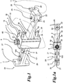
- a door arrester 1 for arresting a door 10, such as a vehicle door, in various opening and closing positions with respect to a body 11, such as a vehicle body.
- the door holder 1 comprises a catch arm 2 and a housing 3. It extends transversely through the housing 3 of the door holder 1 through a through opening 36 provided therein and is arranged approximately perpendicular to the height of the housing 3. It protrudes beyond the housing 3 on two opposite sides.
- the tentacle has a large projecting, massive tentacle arm head 21, which serves as a stop element for the door 10, such as a vehicle door, or the housing 3, to which such a door can be attached.
- the second end 22 of the tentacle arm 2 opposite the tentacle arm head 21 is provided with a hinge eye 23 which is received in a bearing element 25 and is connected to it in an articulated manner by a hinge pin 24.
- the bearing element 25 can be part of an in Figure 1, 1a partially indicated body 11 or be attached to this for the articulated connection of the tentacle arm 2 to the body 11, in particular a vehicle body.
- To attach the bearing element 25 to such a vehicle body this is in the in Figure 1 and 1a
- the embodiment shown is provided with an elongated opening 26 into which a fastening means, such as a screw, can engage and accordingly create a connection to the vehicle body.
- a fastening means such as a screw
- At least one housing section 30 of the housing 3 pointing in the direction of the second end 22 of the tentacle arm 2 has two threaded bolts 31, 32.
- the two threaded bolts 31, 32 are screwed into two threaded openings 33, 34 in the housing section 30 and one section protrudes beyond the outside 35 of the housing 3.
- the respective section of the threaded bolts 31, 32 protruding beyond the outside 35 of the housing section 30 is used in particular to engage in corresponding openings in the door 10 or vehicle door in order to releasably connect them to the housing 3 of the door holder 1 via the threaded bolts 31, 32.
- fastening means such as screws or screw bolts
- fastening means can also be provided on the side of the door, which can engage in the corresponding threaded openings 33, 34 in the housing section 30 of the housing 3 and can hold onto them.
- another type of releasable or fixed connection of the housing 3 to the door 10, such as a vehicle door can also be created.
- the embodiment variant shown is provided with two locking grooves 27.
- the locking grooves 27 can either only be provided on a first outer side 120 of the tentacle arm or both on the first outer side 120 locking grooves 27 and on the opposite second outer side 121 of the tentacle arm 2 locking grooves 28 Figure 2 to see.
- sliders 4, 5 arranged in a guide opening 37 provided there can engage in the locking grooves 27, 28, as shown in FIG Figure 2 can also be seen.
- the door 10 thus remains at the corresponding opening angle with respect to the body, in particular of a vehicle, when the at least one slider 4, 5 is in one of the. Latching grooves 27, 28 remain or latched.
- the two sliders 4, 5 are each cup-shaped, each comprising an end wall section 40, 50 and a jacket or circumferential wall section 41 or 51. With the respective end wall section 40, 50, the sliders 4, 5 engage in the locking grooves 27, 28 a.
- the locking grooves extend along a through and guide opening 29 of the tentacle arm 2 extending in the longitudinal direction of the tentacle arm 2.
- the end wall section 40, 50 is, as in particular Figure 2 or the detail of the housing 3 in Figure 5 can be removed particularly well, provided with an outside circumferential rounded edge in order to be able to slide better into and out of the locking grooves 27, 28.
- the respective casing or circumferential wall section 41 or 51 of the slider 4, 5 rests in the guide opening 37 on the housing wall 38 surrounding it.
- the sliders 4, 5 are completely inserted into the guide opening 37 in the housing 3, in particular with regard to their respective casing or circumferential wall section 41, 51.
- a connecting element 6 is provided, which is bolt-shaped or rod-shaped and extends within the two sliders 4, 5 and through a respective opening 42, 52 in the respective end wall section 40, 50 of the sliders 4, 5 and through a passage and Guide opening 29 in the tentacle arm 2 extends therethrough.
- a connecting element 6 is biased against the two Sliders 4, 5 are provided. This can be exercised by a spring element 7, as in the embodiments according to FIG Figure 2 and Figure 5 shown.
- the spring element 7 is received in the cup-shaped slider 4 in its inner cavity, which is delimited by the jacket or circumferential wall section 41. It extends spirally around the connecting element 6 and is supported with its first end 70 on the inside 43 of the front wall section 40 of the slider 4 and with its opposite second end 71 on an end-side axial limiting device 60 extending transversely to the longitudinal extension of the connecting element 6 at this.
- the axial limiting device 60 at the end is designed, for example, in the form of a disk.
- the connecting element 6 has a rod-shaped or rod-shaped elongated section 61. This protrudes, for example, at its one end 62 like a rivet head and is provided there with the axial limiting device 60, here in the form of a disk.
- the opposite second end 63 of the connecting element 6 can also protrude, as in FIG Figure 2 to 5 shown with a Outside diameter which clearly exceeds the clear width of the opening 52 in the front wall section 50 of the slider 5, so that the connecting element 6 can be supported with its second end 63 on the inside 53 of the front wall section 50.
- the spring element 7 is designed as a compression spring, so that it ensures that both sliders 4, 5 can be kept pretensioned against the two outer sides 120, 121 of the tentacle arm 2.
- the connecting element 6 projects with its first end 62 together with the second end 71 of the spring element 7 beyond the outer side 39 of the housing 3.
- the connecting element 6 is accordingly accessible from the outside, i.e. from outside the housing 3, so that an adjustment or adaptation of the pretensioning force of the spring element 7 designed as a compression spring on the one hand during the assembly of the door holder 1 on a vehicle door and a vehicle body in particular, on the other hand in the course allows normal use, thus creating an adjustment option.
- a tolerance of the support length of the spring element 7 within the housing 3 advantageously has no effect or at least essentially no effect on the spring preload of the latter.
- the passage and guide opening 29 extends through the tentacle arm 2 and in the longitudinal direction of the tentacle arm 2, so that the connecting element 6 extends along the length of the tentacle arm 2 when moving relative to the housing 3 Passage and guide opening 29 can move in this guided.
- the rod-shaped elongated section 61 of the connecting element 6 is in particular provided with a prismatic cross-section in order to enable particularly good and secure guidance of the connecting element or its rod-shaped elongated section 61 in the through and guide opening 29 of the tentacle arm 2.
- the passage and guide opening 29 extending in the longitudinal direction of the tentacle is in particular the Figures 1, 1a as well as 6 and 7.
- a closed flow of force takes place within the system made up of the two sliders 4, 5, the spring element 7 and the connecting element 6. Since the sliders 4, 5 are guided within the guide opening 37 in the housing 3, a system that floats in the direction of force of the spring element 7 and always adapts to the position of the tentacle arm 2 is created. Positional deviations of the door arrester 1 with respect to the body 11, in particular the vehicle body, or the door 10, in particular the vehicle door, have a smaller effect than in the case of the door arresters of the prior art.
- the passage and guide opening 29, which extends in particular only in the area of movement of the tentacle arm 2 in the housing 3 when opening and closing the door 10, such as a vehicle door, reliably guides the connecting element 6 along the tentacle arm 2.
- the second end 63 of the connecting element 6 can in the in the Figures 2 and 5
- the embodiment variant shown of the door arrester 1 is not only arranged to be movable with respect to the slider 5, but can also be firmly connected to it. It is also possible that a uniform component is provided which consists of the slider 4 or 5 and the connecting element 6, so that the slider 4 or 5 and the connecting element 6 are formed as a unit with its second end 63 or, alternatively, its first end 62 . If a unit or a uniform component is provided, comprising, for example, slider 5 and connecting element 6, connecting element 6 can still be movably arranged in slider 4 or its opening 42 provided in front wall section 40:
- only one spring element can alternatively be arranged in the slider 5 or, for example, two spring elements 7, 8 in both sliders 4, 5, as in FIG Figure 3 indicated.
- the connecting element 6 is made longer in the area of its rod-shaped elongated section 61 than in the embodiment according to FIG Figure 2 and 3 so that both spring elements 7, 8 are received on this and can be supported at the end on the one hand on the respective inner side 43 or 53 of the two sliders 4, 5 and on the other hand at the end on the connecting element 6 or its two end axial limiting devices 60, 64.
- the two end-side axial limiting devices 60, 64 are in the embodiment according to Figure 3 also disc-shaped, the connecting element 6 protruding at its two ends 62, 63 in the manner of a rivet head, so that the two disc-shaped end-side axial limiting devices 60, 64 can be supported against it.
- the first spring element 7 and the second spring element 8 are each supported on the opposite side of the respective disk-shaped end-side axial limiting device 60, 64. Both spring elements 7, 8 are each partially received in the inner cavity of the cup-shaped slider 4, 5 and protrude with their other end, i.e. the end 71 of the spring element 7 and the end 81 of the spring element 8, over the outside 39 and 139 of the housing 3 addition.
- the spring element 8 With its first end 80, the spring element 8 is supported on the inside 53 of the front wall section 50 of the slider 5.
- the connecting element 6 is thus movably arranged and guided in both sliders or their respective end openings 42 and 52 and in the through or guide opening 29 of the tentacle arm 2.
- the slide support piece 9 is like the slide 5 according to FIG Figure 2 , 3 and 5 , also arranged in the guide opening 37 of the housing 3 of the door holder 1.
- the slide support piece is cup-shaped and, in contrast to the slider 5, does not have a contoured front wall section, but an essentially flat one front wall section 90 and a jacket or circumferential wall section 91 adjoining it approximately at right angles.
- the front wall section 90 also has an opening 92 through which the connecting element 6 extends.
- the sliding support piece 9 In contrast to the slider 5, however, the sliding support piece 9 only has a supporting function on the catch arm 2, so that the catch arm 2 is formed on its second outer side 121 without locking grooves. Thus, locking grooves 27 are only provided on the first outer side 120.
- the second outer side 121 on the other hand, is designed to be smooth, so that the sliding support piece can be positioned at any point along the tentacle independent of the detent position and held by the frictional force between the front outer side 94 and the second outer side 121 of the tentacle arm 2.
- a pretensioning takes place in turn via the spring element 7 in cooperation with the connecting element 6, the slider 4 and the sliding support piece 9, which are supported on the outside of the tentacle arm 2.
- the sliding support piece 9 is provided, so-called comfort areas can be formed in which a door 10, which is or is connected to the housing 3 the end face outer side 94 of the sliding support piece 9 against the second outer side 121 of the tentacle arm 2.
- the end axial limiting device 60 can, as in FIGS Figures 2 to 5 indicated, are disc-like, in particular in cooperation with a slightly protruding first end 62 of the connecting element 6.
- the end-side axial limiting device can, however, also be designed in the form of a clamping disk 65.
- the clamping disk 65 has clamping sections 66 pointing in the direction of the rod-shaped elongated section 61, which clamp sections are held on the rod-shaped elongated section 61. This clamping holding is possible in any position along the rod-shaped elongated section 61 of the connecting element 6.
- the desired pretensioning force of the spring element 7, which is designed as a compression spring, can be achieved by specifically pushing the clamping disk 65 onto the rod-shaped elongated section 61 of the connecting element 6 can be adjusted continuously.
- FIG. 7 An alternative embodiment variant is shown in which the rod-shaped elongated section 61 of the connecting element 6 is provided with an external thread at least at its first end 62, onto which a nut element 67 can be fitted or screwed.
- the nut element 67 itself has a plate-like protruding section which is arranged in the direction of the spring element 7 in order to create a support surface for it, or an additional disk element can be provided on which the second end 71 of the spring element 7 is supported and which can be moved axially along the rod-shaped elongated section 61 of the connecting element 6 via the nut element 67.
- the embodiment variant shown projects the nut element 67 with a plate-shaped section 68 in the direction of the spring element 7.
- the pretensioning force exerted on the tentacle arm 2 by the spring element 7 via the slider or sliders 4, 5 or the slider 4 and the sliding support piece 9 can be achieved by controlled or targeted tightening of the nut element 67 on the external thread first end 62 of the rod-shaped elongated portion 61 of the connecting element 6 can also be adjusted continuously.
- axial limiting devices 60 or 64 at the end can be provided on the connecting element 6, both fixed and adjustable in steps or continuously.
- the sliders, spring elements and possibly provided slide support pieces can be varied even further compared to the embodiment variants shown in the figures and described above.
- At least one slider and at least one spring element biasing the at least one slider against the at least one tentacle arm can be formed, in particular also any combination of the features mentioned above and shown in the figures, in each case at least one connecting element for connecting the at least one slider to the at least one tentacle arm is provided, the at least one tentacle arm having at least one passage and guide opening through which the at least one connecting element extends and, in cooperation with the at least one spring element, biases the at least one slider against the tentacle arm.
Landscapes
- Engineering & Computer Science (AREA)
- Mechanical Engineering (AREA)
- Lock And Its Accessories (AREA)
Priority Applications (2)
| Application Number | Priority Date | Filing Date | Title |
|---|---|---|---|
| EP19000559.5A EP3835521A1 (fr) | 2019-12-13 | 2019-12-13 | Arrêt de porte ainsi que porte de véhicule et véhicule doté d'au moins un arrêt de porte |
| EP20000466.1A EP3835522A1 (fr) | 2019-12-13 | 2020-12-14 | Butée de porte ainsi que porte de véhicule et véhicule doté d'au moins une butée de porte |
Applications Claiming Priority (1)
| Application Number | Priority Date | Filing Date | Title |
|---|---|---|---|
| EP19000559.5A EP3835521A1 (fr) | 2019-12-13 | 2019-12-13 | Arrêt de porte ainsi que porte de véhicule et véhicule doté d'au moins un arrêt de porte |
Publications (1)
| Publication Number | Publication Date |
|---|---|
| EP3835521A1 true EP3835521A1 (fr) | 2021-06-16 |
Family
ID=68917294
Family Applications (2)
| Application Number | Title | Priority Date | Filing Date |
|---|---|---|---|
| EP19000559.5A Withdrawn EP3835521A1 (fr) | 2019-12-13 | 2019-12-13 | Arrêt de porte ainsi que porte de véhicule et véhicule doté d'au moins un arrêt de porte |
| EP20000466.1A Withdrawn EP3835522A1 (fr) | 2019-12-13 | 2020-12-14 | Butée de porte ainsi que porte de véhicule et véhicule doté d'au moins une butée de porte |
Family Applications After (1)
| Application Number | Title | Priority Date | Filing Date |
|---|---|---|---|
| EP20000466.1A Withdrawn EP3835522A1 (fr) | 2019-12-13 | 2020-12-14 | Butée de porte ainsi que porte de véhicule et véhicule doté d'au moins une butée de porte |
Country Status (1)
| Country | Link |
|---|---|
| EP (2) | EP3835521A1 (fr) |
Citations (6)
| Publication number | Priority date | Publication date | Assignee | Title |
|---|---|---|---|---|
| EP0574723A1 (fr) * | 1992-06-17 | 1993-12-22 | ED. Scharwächter GmbH & Co.KG. | Arrêt de porte pour véhicules automobiles |
| WO2001090518A1 (fr) | 2000-05-20 | 2001-11-29 | Edscha Ag | Arret de porte a element de coulissement et de pression spherique |
| DE10251174B4 (de) | 2002-10-31 | 2009-09-03 | Edscha Ag | Türfeststeller |
| EP2682547A1 (fr) * | 2013-03-08 | 2014-01-08 | Metalsa Automotive GmbH | Arrêt de portière pour véhicules automobiles |
| DE202019104457U1 (de) * | 2018-08-13 | 2019-11-18 | Edscha Engineering Gmbh | Haltergehäuse für einen Türfeststeller sowie Türfeststeller |
| WO2020035111A1 (fr) * | 2018-08-13 | 2020-02-20 | Edscha Engineering Gmbh | Arrêt de porte |
Family Cites Families (1)
| Publication number | Priority date | Publication date | Assignee | Title |
|---|---|---|---|---|
| JP5051578B2 (ja) * | 2007-06-14 | 2012-10-17 | 日本発條株式会社 | 自動車用ドアチェック装置 |
-
2019
- 2019-12-13 EP EP19000559.5A patent/EP3835521A1/fr not_active Withdrawn
-
2020
- 2020-12-14 EP EP20000466.1A patent/EP3835522A1/fr not_active Withdrawn
Patent Citations (6)
| Publication number | Priority date | Publication date | Assignee | Title |
|---|---|---|---|---|
| EP0574723A1 (fr) * | 1992-06-17 | 1993-12-22 | ED. Scharwächter GmbH & Co.KG. | Arrêt de porte pour véhicules automobiles |
| WO2001090518A1 (fr) | 2000-05-20 | 2001-11-29 | Edscha Ag | Arret de porte a element de coulissement et de pression spherique |
| DE10251174B4 (de) | 2002-10-31 | 2009-09-03 | Edscha Ag | Türfeststeller |
| EP2682547A1 (fr) * | 2013-03-08 | 2014-01-08 | Metalsa Automotive GmbH | Arrêt de portière pour véhicules automobiles |
| DE202019104457U1 (de) * | 2018-08-13 | 2019-11-18 | Edscha Engineering Gmbh | Haltergehäuse für einen Türfeststeller sowie Türfeststeller |
| WO2020035111A1 (fr) * | 2018-08-13 | 2020-02-20 | Edscha Engineering Gmbh | Arrêt de porte |
Also Published As
| Publication number | Publication date |
|---|---|
| EP3835522A1 (fr) | 2021-06-16 |
Similar Documents
| Publication | Publication Date | Title |
|---|---|---|
| EP4234864B1 (fr) | Arrêt de porte | |
| EP3586018B1 (fr) | Dispositif de fixation et module de fixation | |
| EP2476500B1 (fr) | Dispositif d'approvisionnement en fil de soudage | |
| EP2668869B1 (fr) | Elément de verrouillage amovible | |
| DE69715068T2 (de) | Scharnier für Türe | |
| EP2031168B1 (fr) | Elément de tampon | |
| WO2000015937A1 (fr) | Dispositif pour guider un element de porte coulissante et en limiter la course | |
| EP0799967A2 (fr) | Trépan de forage avec centrage du foret | |
| DE102019124722A1 (de) | Türfeststellermechanismus | |
| EP3911553B1 (fr) | Colonne de direction pour un véhicule automobile | |
| EP2682547A1 (fr) | Arrêt de portière pour véhicules automobiles | |
| EP2951374B1 (fr) | Pièce coulissante servant à guider une partie de meuble dans un sens de guidage sur une glissière et ferrure de meuble | |
| DE1915751C3 (de) | Schwenklagerung für Türhaltebänder von Türfeststellern für Kraftwagentüren | |
| EP1610997A1 (fr) | Dispositif de serrage pour bloquer la position d'une colonne de direction | |
| DE19914860A1 (de) | Einrichtung zur Führung und Wegbegrenzung eines Schiebetürelements | |
| EP3835521A1 (fr) | Arrêt de porte ainsi que porte de véhicule et véhicule doté d'au moins un arrêt de porte | |
| DE102013211864B4 (de) | Anordnung zur Befestigung eines Pfostens an einer Kunststoff-Rahmenleiste eines Fensters oder einer Türe mittels eines Pfostenverbinders aus Kunststoff | |
| EP3809093A1 (fr) | Dispositif de montage pour une lunette de visée dans une arme de chasse ou de sport doté d'au moins un boulon d'entretoisement à ressort | |
| EP0568858B1 (fr) | Dispositif de verrouillage d'un piston commandé par pression, en particulier pour la commande d'une barre antirenversement d'un véhicule | |
| DE102014103558B3 (de) | Selbstschließendes Rollentürband | |
| DE29505752U1 (de) | Vorrichtung zum Verbinden von Platten mittels Verschraubung | |
| DE102004045254B4 (de) | Anhängerkupplung mit Zugstangenbefestigung | |
| EP2682548A1 (fr) | Arrêt de portière pour véhicules automobiles | |
| EP1963604A1 (fr) | Pièce coulissante pour ferrure | |
| DE102023114287B3 (de) | Stellantrieb für eine Fahrzeugklappe und Verfahren zur Verschwenkung einer Fahrzeugklappe |
Legal Events
| Date | Code | Title | Description |
|---|---|---|---|
| PUAI | Public reference made under article 153(3) epc to a published international application that has entered the european phase |
Free format text: ORIGINAL CODE: 0009012 |
|
| STAA | Information on the status of an ep patent application or granted ep patent |
Free format text: STATUS: THE APPLICATION HAS BEEN PUBLISHED |
|
| AK | Designated contracting states |
Kind code of ref document: A1 Designated state(s): AL AT BE BG CH CY CZ DE DK EE ES FI FR GB GR HR HU IE IS IT LI LT LU LV MC MK MT NL NO PL PT RO RS SE SI SK SM TR |
|
| STAA | Information on the status of an ep patent application or granted ep patent |
Free format text: STATUS: THE APPLICATION IS DEEMED TO BE WITHDRAWN |
|
| 18D | Application deemed to be withdrawn |
Effective date: 20211217 |